[an error occurred while processing this directive]

Support

Troubleshooting IBM

Hierarchical Navigation

 Feedback

Table Of Contents

Troubleshooting IBM

DLSw

SDLC

Technology Basics

Frame Format

SRB

SRB Algorithm

Frame Format

Troubleshooting IBM

Local SRB: Host Cannot Connect to Server

Local SRB: Routing Does Not Function

RSRB: Host Cannot Connect to Server (Peers Not Open)

RSRB: Host Cannot Connect to Server (Peers Open)

RSRB: Periodic Communication Failures

RSRB: NetBIOS Client Cannot Connect to Server

Translational Bridging: Client Cannot Connect to Server

SRT Bridging: Client Cannot Connect to Server

SDLC: Router Cannot Communicate with SDLC Device

SDLC: Intermittent Connectivity

SDLC: Client Cannot Connect to Host over Router Running SDLLC

Virtual Token Ring Addresses and SDLLC

SDLC: Sessions Fail over Router Running STUN

CIP: CLAW Connection Does Not Come Up

CIP: No Enabled LED On

CIP: CIP Will Not Come Online to Host

CIP: Router Cannot ping Host, or Host Cannot ping Router

CIP: Host Cannot Reach Remote Networks

CIP: Host Running Routed Has No Routes


Troubleshooting IBM


This chapter focuses on connectivity and performance problems associated with bridging and routing in IBM-based networks. When troubleshooting IBM-based networks, it is important to have a knowledge of Synchronous Data Link Control (SDLC) and source-route bridging (SRB), as well as data-link switching (DLSw). The following sections provide an overview of DLSw, SDLC, and SRB.

DLSw

Data-link switching was developed to provide support for SNA and NetBIOS in multiprotocol routers. SNA and NetBIOS are basically connection-oriented protocols, so the data link control procedure that they use on the LAN is IEEE 802.2 Logical Link Control (LLC) Type 2. Data-link switching also accommodates SNA protocols over WAN links via the SDLC protocol. For more information about DLSw, refer to RFC 1795, which defines the protocol.

For more information about troubleshooting DLSw problems, refer to the online "DLSw Troubleshooting Guide" at www.cisco.com/warp/customer/697/dlswts1.html.

SDLC

IBM developed the SDLC protocol in the mid-1970s for use in Systems Network Architecture (SNA) environments. SDLC was the first of an important new breed of link-layer protocols based on synchronous, bit-oriented operation. Compared to synchronous character-oriented (for example, Bisync, from IBM) and synchronous byte count-oriented protocols (for example, Digital Data Communications Message Protocol [DDCMP], from Digital Equipment Corporation), bit-oriented synchronous protocols are more efficient, more flexible, and often faster.

After developing SDLC, IBM submitted it to various standards committees. The International Organization for Standardization (ISO) modified SDLC to create the High-Level Data Link Control (HDLC) protocol. The International Telecommunications Union-Telecommunications Standards Section (ITU-T, formerly CCITT) subsequently modified HDLC to create Link Access Procedure (LAP) and then Link Access Procedure, Balanced (LAPB). The Institute of Electrical and Electronic Engineers (IEEE) modified HDLC to create IEEE 802.2. Each of these protocols has become important in its own domain. SDLC remains the SNA primary link-layer protocol for wide-area network (WAN) links.

Technology Basics

SDLC supports a variety of link types and topologies. It can be used with point-to-point and multipoint links, bounded and unbounded media, half-duplex and full-duplex transmission facilities, and circuit-switched and packet-switched networks.

SDLC identifies two types of network nodes:

Primary—Controls the operation of other stations (called secondaries). The primary polls the secondaries in a predetermined order. Secondaries can then transmit if they have outgoing data. The primary also sets up and tears down links and manages the link while it is operational.

Secondary—Is controlled by a primary. Secondaries can send information only to the primary, but they cannot do this unless the primary gives permission.

SDLC primaries and secondaries can be connected in four basic configurations:

Point-to-point—Involves only two nodes, one primary and one secondary.

Multipoint—Involves one primary and multiple secondaries.

Loop—Involves a loop topology, with the primary connected to the first and last secondaries. Intermediate secondaries pass messages through one another as they respond to the requests of the primary.

Hub go-ahead—Involves an inbound and an outbound channel. The primary uses the outbound channel to communicate with the secondaries. The secondaries use the inbound channel to communicate with the primary. The inbound channel is daisy-chained back to the primary through each secondary.

Frame Format

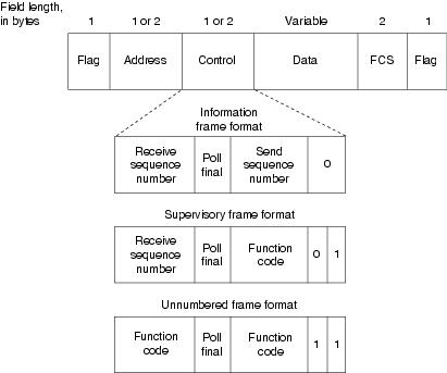
The SDLC frame format is shown in Figure 10-1.

Figure 10-1 The SDLC Frame Format

As Figure 10-1 shows, SDLC frames are bounded by a unique flag pattern. The Address field always contains the address of the secondary involved in the current communication. Because the primary is either the communication source or destination, there is no need to include the address of the primary—it is already known by all secondaries.

The Control field uses three different formats, depending on the type of SDLC frame used. The three SDLC frames are described as follows:

Information (I) frames—These frames carry upper-layer information and some control information. Send and receive sequence numbers and the poll final (P/F) bit perform flow and error control. The send sequence number refers to the number of the frame to be sent next. The receive sequence number provides the number of the frame to be received next. Both the sender and the receiver maintain send and receive sequence numbers. The primary uses the P/F bit to tell the secondary whether it requires an immediate response. The secondary uses this bit to tell the primary whether the current frame is the last in its current response.

Supervisory (S) frames—These frames provide control information. They request and suspend transmission, report on status, and acknowledge the receipt of I frames. They do not have an Information field.

Unnumbered (U) frames—As the name suggests, these frames are not sequenced. They are used for control purposes. For example, they are used to initialize secondaries. Depending on the function of the unnumbered frame, its Control field is 1 or 2 bytes. Some unnumbered frames have an Information field.

The frame check sequence (FCS) precedes the ending flag delimiter. The FCS is usually a cyclic redundancy check (CRC) calculation remainder. The CRC calculation is redone in the receiver. If the result differs from the value in the sender's frame, an error is assumed.

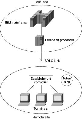
A typical SDLC-based network configuration appears in Figure 10-2. As illustrated, an IBM establishment controller (formerly called a cluster controller) in a remote site connects to dumb terminals and to a Token Ring network. In a local site, an IBM host connects (via channel-attached techniques) to an IBM front-end processor (FEP), which can also have links to local Token Ring local-area networks (LANs) and an SNA backbone. The two sites are connected through an SDLC-based 56-kbps leased line.

Figure 10-2 A Typical SDLC-Based Network Configuration

SRB

The SRB algorithm was developed by IBM and proposed to the IEEE 802.5 committee as the means to bridge among all LANs. The IEEE 802.5 committee subsequently adopted SRB into the IEEE 802.5 Token Ring LAN specification.

Since its initial proposal, IBM has offered a new bridging standard to the IEEE 802 committee: the source-route transparent (SRT) bridging solution. SRT bridging eliminates pure SRBs entirely, proposing that the two types of LAN bridges be transparent bridges and SRT bridges. Although SRT bridging has support, SRBs are still widely deployed.

SRB Algorithm

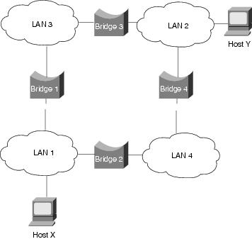
SRBs are so named because they assume that the complete source-to-destination route is placed in all inter-LAN frames sent by the source. SRBs store and forward the frames as indicated by the route appearing in the appropriate frame field. Figure 10-3 illustrates a sample SRB network.

Figure 10-3 A Sample SRB Network

Referring to Figure 10-3, assume that Host X wants to send a frame to Host Y. Initially, Host X does not know whether Host Y resides on the same LAN or a different LAN. To determine this, Host X sends out a test frame. If that frame returns to Host X without a positive indication that Host Y has seen it, Host X must assume that Host Y is on a remote segment.

To determine the exact remote location of Host Y, Host X sends an explorer frame. Each bridge receiving the explorer frame (Bridges 1 and 2, in this example) copies the frame onto all outbound ports. Route information is added to the explorer frames as they travel through the internetwork. When Host X's explorer frames reach Host Y, Host Y replies to each individually using the accumulated route information. Upon receipt of all response frames, Host X chooses a path based on some predetermined criteria.

In the example in Figure 10-3, this process will yield two routes:

LAN 1 to Bridge 1, to LAN 3, to Bridge 3, to LAN 2

LAN 1 to Bridge 2, to LAN 4, to Bridge 4, to LAN 2

Host X must select one of these two routes. The IEEE 802.5 specification does not mandate the criteria that Host X should use in choosing a route, but it does make several suggestions, including the following:

First frame received

Response with the minimum number of hops

Response with the largest allowed frame size

Various combinations of these criteria

In most cases, the path contained in the first frame received will be used.

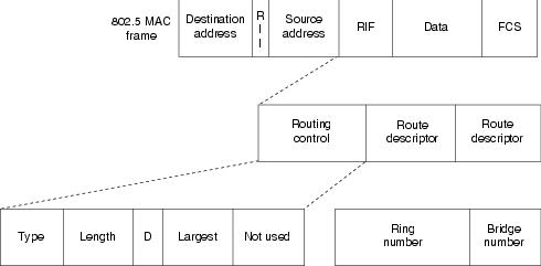
After a route is selected, it is inserted into frames destined for Host Y in the form of a routing information field (RIF). A RIF is included only in those frames destined for other LANs. The presence of routing information within the frame is indicated by the setting of the most significant bit within the Source Address field, called the routing information indicator (RII) bit.

Frame Format

The IEEE 802.5 RIF is structured as shown in Figure 10-4.

Figure 10-4 The IEEE 802.5 RIF

The fields of the RIF are as follows:

The Routing Control field, which consists of the following subfields:

The Type subfield in the RIF indicates whether the frame should be routed to a single node, a group of nodes that make up a spanning tree of the internetwork, or all nodes. The first type is called a specifically routed frame, the second type is called a spanning-tree explorer, and the third type is called an all-paths explorer. The spanning-tree explorer can be used as a transit mechanism for multicast frames. It can also be used as a replacement for the all-paths explorer in outbound route queries. In this case, the destination responds with an all-paths explorer.

The Length subfield indicates the total length (in bytes) of the RIF.

The D bit indicates the direction of the frame (forward or reverse).

The largest field indicates the largest frame that can be handled along this route.

The Route Descriptor field, of which there can be more than one. Each route descriptor field carries a ring number/bridge number pair that specifies a portion of a route. Routes, then, are simply alternating sequences of LAN and bridge numbers that start and end with LAN numbers.

Troubleshooting IBM

This section focuses on connectivity and performance problems associated with bridging and routing in IBM-based networks. This section covers specific IBM-related symptoms, the problems that are likely to cause each symptom, and the solutions to those problems.

This section covers the most common network issues in IBM networks:

Local SRB: Host Cannot Connect to Server

Local RSRB: Routing Does Not Function

RSRB: Host Cannot Connect to Server (Peers Not Open)

RSRB: Host Cannot Connect to Server (Peers Open)

RSRB: Periodic Communication Failures

RSRB: NetBIOS Client Cannot Connect to Server

Translational Bridging: Client Cannot Connect to Server

SRT Bridging: Client Cannot Connect to Server

SDLC: Router Cannot Communicate with SDLC Device

SDLC: Intermittent Connectivity

SDLC: Client Cannot Connect to Host over Router Running SDLLC

SDLC: Sessions Fail over Router Running STUN

CIP: CLAW Connection Does Not Come Up

CIP: No Enabled LED On

CIP: CIP Will Not Come Online to Host

CIP: Router Cannot ping Host, or Host Cannot ping Router

CIP: Host Cannot Reach Remote Networks

CIP: Host Running Routed Has No Routes

Local SRB: Host Cannot Connect to Server

Symptom: Connections fail over a router configured as an SRB connecting two or more Token Rings.

Table 10-1 outlines the problems that might cause this symptom and describes solutions to those problems.

Table 10-1 Local SRB: Host Cannot Connect to Server  

Possible Problem
Solution

Ring number mismatch

A router interface configured for bridging fails to insert into a ring when it detects a ring number mismatch, and it posts an error message to the console.

1. Get the ring number (specified in hexadecimal) from IBM SRBs (either by examining the configuration of other SRBs or from the system administrator).

2. Use the show running-config (or simply show run) privileged exec command to view the configuration of routers configured as SRBs. Look for source-bridge interface configuration command entries that assign ring numbers (displayed in decimal) to the rings that are connected to the router's interfaces.1

For example, the following configuration entry shows the entry for local ring 10, bridge number 500, and remote ring 20:

source-bridge 10 500 20

Note: Parallel bridges situated between the same two rings must have different bridge numbers.

3. Convert IBM SRB ring numbers to decimal, and verify that the ring numbers configured on all internetworking nodes agree.

4. If the ring numbers do not agree, reconfigure the router interface or IBM SRBs so that the ring numbers match. Use the source-bridge command to make configuration changes; the syntax is as follows:

source-bridge source-ring-number bridge-number target-ring-number [conserve-ring]

Syntax description:

source-ring-number—Ring number for the interface's Token Ring or FDDI2 ring. It must be a decimal number in the range 1 to 4095 that uniquely identifies a network segment or ring within the bridged Token Ring or FDDI network.

bridge-number—Number that uniquely identifies the bridge connecting the source and target rings. It must be a decimal number in the range 1 to 15.

target-ring-number—Ring number of the destination ring on this router. It must be unique within the bridged Token Ring or FDDI network. The target ring can also be a ring group. This must be a decimal number.

Ring number mismatch (continued)

conserve-ring—(Optional) Keyword to enable SRB over Frame Relay. When this option is configured, the SRB software does not add the ring number associated with the Frame Relay PVC,3 the partner's virtual ring, to outbound explorer frames. This option is permitted for Frame Relay subinterfaces only.

Example:

In the following example, Token Rings 129 and 130 are connected via a router:

interface tokenring 0
 source-bridge 129 1 130
!
interface tokenring 1
 source-bridge active 130 1 129

End system that does not support RIF4

1. Place a network analyzer on the same ring to which the end system is connected.

2. Look for RIF frames sent from the end system (RIF frames have the high-order bit of the source MAC5 address set to 1).

3. If no RIF frames are found, the end system does not support RIF and cannot participate in source routing.

If the protocol is routable, you can route the protocol or configure transparent bridging. If you use transparent bridging, be careful not to create loops between the SRB and the transparent bridging domains.

4. If your environment requires SRB, contact your workstation or server vendor for SRB drivers or for information about setting up your workstation or server to support SRB.

Hop count exceeded

Use the show protocol route command to check the hop count values on routers and bridges in the path. Packets that exceed the hop count are dropped.

Alternatively, you can enable the debug source event privileged exec command to see whether packets are being dropped because the hop count has been exceeded.

Hop count exceeded (continued)

Caution: Because debugging output is assigned high priority in the CPU process, it can render the system unusable. For this reason, use debug commands only to troubleshoot specific problems or during troubleshooting sessions with Cisco technical support staff. Moreover, it is best to use debug commands during periods of lower network traffic and fewer users. Debugging during these periods decreases the likelihood that increased debug command processing overhead will affect system use. Remember to use the undebug all command to turn off debugging after troubleshooting.

Increase the hop count if it is less than the default value, 7. Otherwise, the network must be redesigned so that no destination is more than seven hops away.

Router that is not configured to forward spanning explorers

Spanning explorer packets are equivalent to a single-route broadcast. Routers must therefore be configured to route them.

1. Use the show source-bridge exec command to determine whether the spanning explorer count is incrementing.

2. If the spanning explorer count is not incrementing, use the show running-config privileged exec command on routers to see whether the source-bridge spanning interface configuration command is configured. This command configures the router to forward spanning explorers.

3. If the command entry is not present in the configuration, add it to any router that is required to pass spanning explorers. The command syntax is as follows:

source-bridge spanning bridge-group [path-cost path-cost]

Syntax description:

bridge-group—Number in the range 1 to 9 that you choose to refer to a particular group of bridged interfaces.

path-cost—(Optional) Path cost for a specified interface.

path-cost—(Optional) Path cost for the interface. The valid range is 0 to 65535.

Example:

The following example adds Token Ring 0 to bridge group 1 and assigns a path cost of 12 to Token Ring 0:

interface tokenring 0

source-bridge spanning 1 path-cost 12

4. Use the show source-bridge exec command to determine whether explorers are being sent.

Router that is not configured to forward spanning explorers (continued)

5. If explorers are not being sent, place a network analyzer on the same ring to which the end system is connected.

6. If you find spanning all-ring frames, use the show running-config privileged exec command to make sure that the router is properly configured. If sessions still cannot be established over the SRB, contact your technical support representative for more assistance.

1 Although you can enter the ring number in hexadecimal or decimal, it always appears in the configuration as a decimal number.

2 FDDI = Fiber Distributed Data Interface

3 PVC= permanent virtual circuit

4 RIF = routing information field

5 MAC = Media Access Control


Local SRB: Routing Does Not Function

Symptom: Routed protocols are not forwarded properly by routers in a local SRB environment. SRBs bridge traffic normally.

Table 10-2 outlines the problems that might cause this symptom and describes solutions to those problems.

Table 10-2 Local SRB: Routing Does Not Function 

Possible Problem
Solution

Routing problem

For detailed information on troubleshooting routing problems, refer to the chapters in this book that cover the routing protocols in question. For example, if you are running Novell IPX, see Chapter 8, "Troubleshooting Novell IPX."

Missing multiring command

1. Use the show running-config privileged exec command on the router. Look for a multiring interface configuration command entry. This command enables the collection and use of RIF information on router interfaces.

2. If the multiring command is not present, add the command to the configuration using the following command:

C4000(config-if)#multiring all

Incomplete ARP1 table

1. Determine whether you can ping hosts.

2. If the host does not respond, use the show arp exec command to determine whether an entry for the host exists in the ARP table.

3. If an entry exists, there is probably a routing problem. Determine whether you have a source-route path to the destination hardware (MAC) address. Use the show rif exec command to match the RIF with the hardware address of the host.

4. If no entry exists, use a network analyzer to see whether ARP requests are getting through to the remote ring and to see whether replies come back.

1 ARP=Address Resolution Protocol


RSRB: Host Cannot Connect to Server (Peers Not Open)

Symptom: Hosts cannot make connections to servers across a router configured as a remote source-routing bridge (RSRB). The output of the show source-bridge privileged exec command shows that SRB peers are not open.


Note If you succeed in getting peers to open, but hosts are still incapable of communicating with servers, refer to the section "RSRB: Host Cannot Connect to Server (Peers Open)," later in this chapter.


Table 10-3 outlines the problems that might cause this symptom and describes solutions to those problems.

Table 10-3 RSRB: Host Cannot Connect to Server (Peers Not Open) 

Possible Problem
Solution

Missing or misconfigured source-bridge remote-peer command on the router

1. Use the show source-bridge exec command to check for remote peers.

If the output shows that peers are open, refer to the section "RSRB: Host Cannot Connect to Server (Peers Open)," later in this chapter.

Missing or misconfigured source-bridge remote-peer command on the router (continued)

2. If the output shows that peers are not open, use the show running-config privileged exec command to view the router configuration. Verify that two source-bridge remote-peer global configuration command entries are present—one should point to the IP address of the local router, and the other should point to the IP address of the remote router.

3. If either or both of the commands are missing or point to the wrong address, add or modify the commands as required.

For detailed information about configuring routers for RSRB, see the Cisco IOS Bridging and IBM Networking Configuration Guide and Bridging and IBM Networking Command Reference.

No route to the remote peer

If you are using TCP1 or FST2 encapsulation between the local and remote SRB, follow these steps:

1. Test IP connectivity using the extended ping privileged exec command. Use the local peer ID as the source address, and the remote peer ID as the destination address.

2. If the ping fails, use the show ip route exec command to view the IP routing table.

3. If the show ip route output does not show a route to the intended remote peer, there is probably an IP routing problem, or a problem with the hardware or cabling in the path from the local to the remote SRB.

For information on troubleshooting IP routing, refer to Chapter 7, "Troubleshooting TCP/IP." For information about troubleshooting hardware problems, see Chapter 3, "Troubleshooting Hardware and Booting."

Serial link problem

If there is a direct connection between the local and remote SRB (that is, if you are not using FST or TCP encapsulation), follow these steps:

1. Check to make sure that the next-hop router is directly adjacent.

2. If the router is adjacent, perform other tests to ensure that the link is functioning properly. For more information, refer to Chapter 15, "Troubleshooting Serial Lines."

3. If the next hop is not directly adjacent, redesign your network so that it is.

End system that is not generating explorer traffic

1. Use the show source-bridge privileged exec command to see whether the explorer count is incrementing.

2. If the explorer count is not incrementing, use the show running-config privileged exec command to view the router configuration. Check for a source-bridge spanning interface configuration command on the local and remote routers.

3. If the source-bridge spanning command is not configured on the routers, configure it on the interfaces connecting the local and remote SRBs. This command is required if the end system is using single-route explorers. The command syntax is as follows:

source-bridge spanning bridge-group [path-cost path-cost]

Syntax description:

bridge-group—Number in the range 1 to 9 that you choose to refer to a particular group of bridged interfaces.

path-cost—(Optional) Path cost for a specified interface.

path-cost—(Optional) Path cost for the interface. The valid range is 0 to 65535.

Example:

The following example adds Token Ring 0 to bridge group 1 and assigns a path cost of 12 to Token Ring 0:

interface tokenring 0

source-bridge spanning 1 path-cost 12

Encapsulation mismatch

1. Use the show interfaces exec command to verify that the interface and line protocol are up. If the status line indicates any other state, refer to Chapter 15.

2. Verify that the configured encapsulation type matches the requirements of the network to which the serial interface is attached.

For example, if the serial interface is attached to a leased line but the configured encapsulation type is Frame Relay, there is an encapsulation mismatch.

3. To resolve the mismatch, change the encapsulation type on the serial interface to the type appropriate for the attached network—for example, change from frame-relay to hdlc.

Hop count exceeded

1. Use the show protocol route command to check the hop count values on routers and bridges in the path. Packets that exceed the hop count are dropped.

Alternatively, you can enable the debug source event privileged exec command to see whether packets are being dropped because the hop count has been exceeded.

Caution: Because debugging output is assigned high priority in the CPU process, it can render the system unusable. For this reason, use debug commands only to troubleshoot specific problems or during troubleshooting sessions with Cisco technical support staff. Moreover, it is best to use debug commands during periods of lower network traffic and fewer users. Debugging during these periods decreases the likelihood that increased debug command processing overhead will affect system use.

2. Increase the hop count if it is less than the default value, 7. Otherwise, the network must be redesigned so that no destination is greater than seven hops away.

1 TCP=Transmission Control Protocol

2 FST=Fast Sequenced Transport


RSRB: Host Cannot Connect to Server (Peers Open)

Symptom: Hosts cannot make connections to servers across a router configured as an RSRB. The output of the show source-bridge privileged exec command shows that SRB peers are open.

The following is an example of output from the show source-bridge command:

ionesco#show source-bridge
[...]
Peers:                 state   lv  pkts_rx  pkts_tx  expl_gn    drops TCP
   TCP 150.136.92.92     -       2       0        0          0     0    0
   TCP 150.136.93.93     open    2*     18       18          3     0    0
[...]

Table 10-4 outlines the problems that might cause this symptom and describes solutions to those problems.

Table 10-4 RSRB: Host Cannot Connect to Server (Peers Open) 

Possible Problem
Solution

End system misconfiguration

1. If the end system is on the ring local to the router, use the show lnm station privileged exec command on the local router. This command lists the stations on the local ring.

The following is an example of the show lnm station command:

show lnm station [address]

Syntax description:

address—(Optional) Address of a specific LNM1 station

Sample Display:

The following is sample output from the show lnm station command when a particular address (in this case, 1000.5abc15) has been specified:

Router# show lnm station 1000.5a6f.bc15
isolating error counts
    station      int  ring  loc.   weight   line  inter 
burst   ac  abort
1000.5a6f.bc15    T1  0001  0000   00 - N   00000 00000 
00000 00000 00000
Unique ID:  0000.0000.0000          NAUN: 0000.3000.abc4
Functional: C000.0000.0000         Group: C000.0000.0000
Physical Location:   00000        Enabled Classes:  0000
Allowed Priority:    00000        Address Modifier: 0000
Product ID:     00000000.00000000.00000000.00000000.0000
Ucode Level:    00000000.00000000.0000
Station Status: 00000000.0000
Last transmit status: 00

2. Check the command output for the MAC address of the workstation or server. If the MAC address is not present in the output, check the configuration of the end system.

3. If the problem persists, use a network analyzer to check network traffic generated by the end system. If you do not have a network analyzer, use the debug token-ring and the debug source-bridge commands.

Caution: Using the debug token-ring and the debug source-bridge commands on a heavily loaded router is not advised. These commands can cause further network degradation or complete network failure if not used judiciously.

4. Check the output of the debug commands to see whether the end system is sending traffic to the correct MAC addresses or destination names (in the case of NetBIOS).

End system that does not support RIF

1. Place a network analyzer on the same ring to which the end system is connected.

2. Look for RIF frames sent from the end system (RIF frames have the high-order bit of the source MAC address set to 1).

3. If no RIF frames are seen, the end system does not support RIF and cannot participate in source routing.

If the protocol is routable, you can route the protocol or configure transparent bridging. If you use transparent bridging, be careful not to create loops between the SRB and the transparent bridging domains.

4. If your environment requires SRB, contact your workstation or server vendor for SRB drivers or for information about setting up your workstation or server to support SRB.

Explorer traffic that is not reaching remote ring

1. Using a network analyzer or the debug source-bridge command, watch network traffic to see whether explorers from the end system reach the remote ring.

2. If traffic reaches the remote ring successfully, check the configuration of the destination end system (for example, a server) to see why that station does not reply to the explorer traffic from the source.

If traffic does not reach the remote ring, use the show source-bridge command to check ring lists. If information about the ring has not been learned, check router configurations.

3. If you are using NetBIOS, use the show netbios name-cache exec command to see whether traffic is passing through the network properly. If it is not, check router configurations.

For detailed information about configuring routers for RSRB, refer to the Cisco IOS Bridging and IBM Networking Configuration Guide and Bridging and IBM Networking Command Reference.

1 LNM=LAN Network Manager


RSRB: Periodic Communication Failures

Symptom: Communication failures occur periodically over a router configured as an RSRB.

Table 10-5 outlines the problems that might cause this symptom and describes solutions to those problems.

Table 10-5 RSRB: Periodic Communication Failures 

Possible Problem
Solution

Misconfigured T1 timers

If you are not using local acknowledgment, misconfigured T1 timers can cause periodic timeouts.

1. Use a network analyzer to see how long it takes for packets to travel from one end of the network to the other. (Note: Inserting a network analyzer to a T1 circuit will bring the circuit down.)

2. Use a ping test to the remote router, and note the round-trip delay. Compare this value with the configured T1 timer values on end systems.

3. If the round-trip delay is close to or exceeds the T1 timer value, acknowledgments are probably being delayed or dropped by the WAN. For delays, increase the T1 configuration on end systems. For drops, check buffers and interface queues.

4. Enable local acknowledgment to see whether that solves the problem.

WAN link problem

For information on troubleshooting serial line problems, refer to Chapter 15. For information on troubleshooting different WAN environments, refer to the appropriate chapter elsewhere in this book.


RSRB: NetBIOS Client Cannot Connect to Server

Symptom: NetBIOS clients cannot connect to NetBIOS servers over a router configured as an RSRB.

Table 10-6 outlines the problems that might cause this symptom and describes solutions to those problems.

Possible Problem
Solution

Incorrect mapping of NetBIOS name cache server-to-client mapping

1. For each router on which NetBIOS name caching is enabled, use the show rif exec command to determine whether the RIF entry shows the correct path from the router to both the client and the server.

Incorrect mapping of NetBIOS name cache server-to-client mapping (continued)

The following is an example of the show rif exec command:

cantatrice#show rif
Codes: * interface, - static, + remote
Hardware Addr  How   Idle (min)  Routing Information 
Field
5C02.0001.4322 rg5           -   0630.0053.00B0
5A00.0000.2333 TR0           3   08B0.0101.2201.0FF0
5B01.0000.4444 -             -   -
0000.1403.4800 TR1           0   -
0000.2805.4C00 TR0           *   -
0000.2807.4C00 TR1           *   -
0000.28A8.4800 TR0           0   -
0077.2201.0001 rg5          10   0830.0052.2201.0FF0

In this display, entries marked with an asterisk (*) are the router's interface addresses. Entries marked with a dash (-) are static entries. Entries with a number denote cached entries. If the RIF timeout is set to something other than the default of 15 minutes, the timeout is displayed at the top of the display.

2. Use the show running-config privileged exec command to view the router configuration. Make sure that the source-bridge proxy-explorer interface configuration command is included in the Token Ring configuration. Proxy explorers must be enabled on any interface that uses NetBIOS name caching.

3. Use the show netbios-cache exec command to see whether the NetBIOS cache entry shows the correct mappings of server and client names to MAC addresses.

The following is an example of the show netbios-cache exec command:

cantatrice#show netbios-cache
  HW Addr          Name            How       Idle      
NetBIOS Packet
                                                       
Savings
1000.5a89.449a     IC6W06_B        TR1       6         
0
1000.5a8b.14e5     IC_9Q07A        TR1       2         
0
1000.5a25.1b12     IC9Q19_A        TR1       7         
0
1000.5a25.1b12     IC9Q19_A        TR1       10        
0
1000.5a8c.7bb1     BKELSA1         TR1       4         
0
1000.5a8b.6c7c     ICELSB1         TR1       -         
0
1000.5a31.df39     ICASC_01        TR1       -         
0
1000.5ada.47af     BKELSA2         TR1       10        
0
1000.5a8f.018a     ICELSC1         TR1       1         
0

Incorrect mapping of NetBIOS name cache server-to-client mapping (continued)

The following are the fields reported by the show netbios-cache command:

show netbios—Cache field descriptions.

HW Addr—MAC address mapped to the NetBIOS name in this entry.

Name—NetBIOS name mapped to the MAC address in this entry.

How—Interface through which this information was learned.

Idle—Period of time (in seconds) since this entry was last accessed. A hyphen in this column indicates that it is a static entry in the NetBIOS name cache.

NetBIOS Packet Savings—Number of packets to which local replies were made (thus preventing transmission of these packets over the network).

4. Use the show running-config privileged exec command at each router to examine the mapping of addresses specified in netbios name-cache global configuration command entries.

The following example shows a configuration in which the NetBIOS server is accessed remotely:

source-bridge ring-group 2
rif 0110.2222.3333 0630.021.0030 ring group 2
netbios name-cache 0110.2222.3333 DEF ring-group 2

Misconfigured source-bridge command

1. For each router on which NetBIOS name caching is enabled, use the show source-bridge command to obtain the version of the remote connection. The value specified should be 2 or 3. If the value is 1, connections will not get through, and you must modify your configuration.

Misconfigured source-bridge command

Example:

The following is sample output from the show source-bridge command:

Router# show source-bridge
Local Interfaces:            receive       transmit
             srn bn  trn r p s n  max hops     cnt         
cnt        drops
TR0            5  1   10 *   *          7    39:1002     
23:62923 
Ring Group 10:
  This peer: TCP 150.136.92.92
   Maximum output TCP queue length, per peer: 100
  Peers:                 state   lv  pkts_rx  
pkts_tx  expl_gn    drops TCP
   TCP 150.136.92.92     -       2       0        0          
0     0    0
   TCP 150.136.93.93     open    2*     18       18          
3     0    0
Rings:
   bn: 1 rn: 5    local  ma: 4000.3080.844b 
TokenRing0            fwd: 18
   bn: 1 rn: 2   remote  ma: 4000.3080.8473 TCP 
150.136.93.93     fwd: 36
Explorers: ------- input -------             ------- 
output -------
       spanning  all-rings     total      spanning  
all-rings     total
  TR0         0          3         3             3          
5         8
Router#

2. If the router is running a software release prior to Cisco IOS Release 10.0, specify either version 2 or version 3 in the source-bridge remote-peer interface configuration command. The syntax is as follows:

source-bridge remote-peer ring-group tcp ip-address [lf size] [local-ack] [priority] [version number]

If the router is running Cisco IOS Release 10.0 or later, the specification of a version is ignored.

For more information, refer to the Cisco IOS Bridging and IBM Networking Configuration Guide and Bridging and IBM Networking Command Reference.


Translational Bridging: Client Cannot Connect to Server

Symptom: Clients cannot communicate over a router configured as a translational bridge.


Caution In certain situations, replacing existing translational bridges with Cisco translational bridges can cause interoperability problems. Some translational bridge implementations map functional addresses between media (such as local-area transport [LAT] functional address 0900.2B00.00FA on Ethernet) to a broadcast address on the Token Ring side (such as C000.FFFF.FFFF). Cisco does not support this functionality. Furthermore, you cannot use translational bridging with any protocol that embeds the MAC address of a station inside the Information field of the MAC frames (examples include IP ARP and Novell IPX).

Table 10-7 outlines the problems that might cause this symptom and describes solutions to those problems.

Table 10-6 Translational Bridging: Client Cannot Connect to Server 

Possible Problem
Solution

Media problem

Verify the line using the show interfaces exec command. If the interface or line protocol is down, troubleshoot the media. For LAN media, refer to the chapter that covers your media type.

Ethernet-to-Token Ring address mapping that is misconfigured

1. Use the show bridge exec command to verify the existence of the Ethernet station.

Ethernet and Token Ring addresses use opposite bit ordering schemes. The Token Ring address 0110.2222.3333 is equivalent to the Ethernet address 8008.4444.cccc.

2. Use the show spanning exec command to determine whether the Ethernet port is in forwarding mode.

Ethernet-to-Token Ring address mapping that is misconfigured (continued)

Example:

The following is sample output from the show span command:

RouterA> show span
Bridge Group 1 is executing the IBM compatible 
spanning tree protocol
  Bridge Identifier has priority 32768, address 
0000.0c0c.f68b
  Configured hello time 2, max age 6, forward delay 
4
  Current root has priority 32768, address 
0000.0c0c.f573
  Root port is 001A (TokenRing0/0), cost of root 
path is 16
  Topology change flag not set, detected flag not 
set
  Times:  hold 1, topology change 30, notification 
30
          hello 2, max age 6, forward delay 4, aging 
300
  Timers: hello 0, topology change 0, notification 0
Port 001A (TokenRing0/0) of bridge group 1 is 
forwarding. Path cost 16
   Designated root has priority 32768, address 
0000.0c0c.f573
   Designated bridge has priority 32768, address 
0000.0c0c.f573
   Designated port is 001B, path cost 0, peer 0
   Timers: message age 1, forward delay 0, hold 0
Port 002A (TokenRing0/1) of bridge group 1 is 
blocking. Path cost 16
   Designated root has priority 32768, address 
0000.0c0c.f573
   Designated bridge has priority 32768, address 
0000.0c0c.f573
   Designated port is 002B, path cost 0, peer 0
   Timers: message age 0, forward delay 0, hold 0
Port 064A (spanRSRB) of bridge group 1 is disabled. 
Path cost 250
   Designated root has priority 32768, address 
0000.0c0c.f573
   Designated bridge has priority 32768, address 
0000.0c0c.f68b
   Designated port is 064A, path cost 16, peer 0
   Timers: message age 0, forward delay 0, hold 0

A port (spanRSRB) is created with each virtual ring group. The port is disabled until one or more peers go into open state in the ring group.

3. Use the show rif exec command to determine whether the target Token Ring station is visible on the internetwork.

When configured for translational bridging, the router extracts the RIF of a packet received from the Token Ring network and saves it in a table. The router then transmits the packet on the Ethernet network. Later, the router reinserts the RIF when it receives a packet destined for the originating node on the Token Ring side.

Ethernet-to-Token Ring address mapping that is misconfigured (continued)

Example:

The following is sample output from the show rif command:

Router# show rif
Codes: * interface, - static, + remote
Hardware Addr  How   Idle (min)  Routing Information 
Field
5C02.0001.4322 rg5           -   0630.0053.00B0
5A00.0000.2333 TR0           3   08B0.0101.2201.0FF0
5B01.0000.4444 -             -   -
0000.1403.4800 TR1           0   -
0000.2805.4C00 TR0           *   -
0000.2807.4C00 TR1           *   -
0000.28A8.4800 TR0           0   -
0077.2201.0001 rg5          10   0830.0052.2201.0FF0

4. If Ethernet and Token Ring end systems are visible, statically configure any relevant server MAC addresses in the client configurations so that clients can listen to the server advertisements directly.

One case in which static mapping is required is when bridging DEC LAT traffic over a translational bridge. LAT services on Ethernet are advertised on a multicast address that is mapped by some translational bridges to a broadcast address on the Token Ring side. Routers do not support this mapping.

Vendor code mismatch

Older Token Ring implementations require that the vendor code (OUT1 field) of the SNAP2 header be 000000. Cisco routers modify this field to be 0000F8 to specify that the frame was translated from Ethernet Version 2 to Token Ring. This can cause problems on older Token Ring networks.

Specify the ethernet-transit-oui interface configuration command to force the router to make the vendor code field 000000. This change is frequently required when there are IBM 8209s (IBM Token Ring-to-Ethernet translating bridges) in the network.

The following is an example of the ethernet-transit-oui command:

ethernet-transit-oui [90-compatible | standard | cisco]

Syntax description:

90-compatible—OUI used 0000F8 by default, when talking to other Cisco routers. It provides the most flexibility.

standard—OUI used 000000 when talking to IBM 8209 bridges and other vendor equipment. It does not provide for as much flexibility as the other two choices.

Vendor code mismatch (continued)

cisco—OUI used 00000C, which provided for compatibility with future equipment.

Example:

The following example specifies Cisco's OUI form:

interface tokenring 0
 ethernet-transit-oui cisco

Cisco and non-Cisco translational bridges in parallel

1. Check for translational bridges in parallel with the Cisco translational bridge. If there are any parallel non-Cisco translational bridges, loops will probably be created.

2. Because implementing translational bridging defeats the spanning-tree mechanism of both transparent bridging and SRB environments, you must eliminate all loops caused by inserting the translational bridge. A transparent spanning tree and a source-bridge spanning tree cannot communicate with one another.

Trying to bridge protocols that embed MAC addresses in the Information field of the MAC frame (such as IP ARP,3 Novell IPX, or AARP4 )

If MAC addresses are embedded in the Information field of the MAC frame, bridges will be incapable of reading the address. Bridges will therefore be incapable of forwarding the traffic.

1. If you are attempting to bridge this type of protocol, route the protocol instead.

2. If you still cannot communicate over the router, contact your technical support representative.

1 OUI=organizationally unique identifier

2 SNAP=Subnetwork Access Protocol

3 ARP=Address Resolution Protocol

4 AARP=AppleTalk Address Resolution Protocol


SRT Bridging: Client Cannot Connect to Server

Symptom: Clients cannot communicate over a router configured to perform SRT bridging. Packets are not forwarded by the SRT bridge.

SRT bridging enables you to implement transparent bridging in Token Ring environments. It is not a means of translating between SRB on a Token Ring and transparent bridging on Ethernet (or other) media.

Table 10-8 outlines the problems that might cause this symptom and describes solutions to those problems.

Table 10-7 SRT Bridging: Client Cannot Connect to Server 

Possible Problem
Solution

Trying to bridge frames containing RIF from Token Ring network to Ethernet network over an SRT bridge

Use translational bridging instead of SRT bridging to allow SRB-to-transparent bridging translation.

Because SRT bridging works only between Ethernet and Token Ring, any packet containing a RIF is dropped when SRT bridging is used.

Attempting to transfer large frame sizes

Problems will occur if Token Ring devices transmit frames exceeding the Ethernet MTU1 of 1500 bytes. Configure hosts on the Token Ring to generate frame sizes less than or equal to the Ethernet MTU.

Trying to bridge protocols that embed the MAC address in the Information field of the MAC frame (such as IP ARP, Novell IPX, or AARP)

If MAC addresses are embedded in the Information field of the MAC frame, bridges will be incapable of reading the address. Bridges will therefore be incapable of forwarding the traffic.

1. If you are attempting to bridge this type of protocol, route the protocol instead.

2. If you still cannot communicate over the router, contact your technical support representative.

Media problem

Verify the line using the show interfaces exec command. If the interface or line protocol is down, troubleshoot the media. For LAN media, refer to the chapter that covers your media type.

1 MTU=maximum transmission unit


SDLC: Router Cannot Communicate with SDLC Device

Symptom: Router cannot communicate with an IBM SDLC device.

Table 10-9 outlines the problems that might cause this symptom and describes solutions to those problems.

Table 10-8 SDLC: Router Cannot Communicate with SDLC Device 

Possible Problem
Solution

Physical layer problem

1. Use the show interfaces exec command to determine whether the interface and line protocol are up.

2. If the interface and line protocol are both up, troubleshoot link-layer problems, as described later in this table.

3. If the output does not indicate that the interface up and the line protocol up, make sure that the device is powered on. Make sure that all cabling is correct, securely connected, and undamaged. Make sure that the cabling does not exceed the recommended length for the speed of the connection.

Physical layer problem (continued)

4. If the interface or line protocol is still down, use a breakout box to check the signals on the line.

Note: On some Cisco platforms, such as the Cisco 7500 running a recent Cisco IOS release, the output of the show interfaces command will indicate the state of line signals.

If the router is full-duplex DCE,1 check for DTR2 and RTS.3 If these signals are not high, proceed to Step 5. If these signals are high, the interface should be up. If it is not, contact your technical support representative.

On a Cisco 7500, if the breakout box shows that the DTR and DTS signals are high, but the show interfaces command shows that they are not, check the router cabling. In particular, make sure that the 60-pin high-density cable is not plugged in to the router upside-down.

If the router is half-duplex DCE, check for DTR. If DTR is not high, proceed to Step 5. If DTR is high, the interface should be up. If it is not, contact your technical support representative.

Note: Half-duplex is not supported on Cisco 7000 series routers.

If the router is full- or half-duplex DTE, check for CD. If CD is not high, proceed to Step 5. If CD is high, the interface should be up. If it is not, contact your technical support representative.

5. If the router is full-duplex DCE, make sure that the device is configured for permanent RTS high. If the device does not allow you to configure permanent RTS, set the signal high by strapping DTR from the device side to RTS on the router side (see Figure 10-5).

6. If the router is DCE, it may be required to provide clock to the device. Make sure that the clock rate interface configuration command is present in the router configuration. Use the show running-config privileged exec command on the router to view the interface configuration. The following example shows the clock rate information for interface serial 0.

Example:

The following example sets the clock rate on the first serial interface to 64000 bits per second:

interface serial 0
 clock rate 64000

If the router is DTE, it should get clock from an external device. Make sure that a device is providing clock properly. Make sure that the clocking source is the same for all devices.

Link-layer problem (router is primary)

1. Use the debug sdlc privileged exec command4 to see whether the router is sending SNRMs.5

Caution: Because debugging output is assigned high priority in the CPU process, it can render the system unusable. For this reason, use debug commands only to troubleshoot specific problems or during troubleshooting sessions with Cisco technical support staff. Moreover, it is best to use debug commands during periods of lower network traffic and fewer users. Debugging during these periods decreases the likelihood that increased debug command processing overhead will affect system use.

2. If the router is not sending SNRMs, check the physical layer (see the preceding problem in this table). If the router is sending SNRMs, the device should send UAs6 in reply.

3. If the device is not sending UAs, make sure that the addresses of the router and device are correct.

4. If you are using a V.35 connection, make sure that the SCT/SCTE7 setting is correct on the interface. The router should use SCTE if the router is DCE, and it should use SCT if the router is DTE.

The SCT/SCTE setting might be changed with a jumper or with the software configuration command dce-terminal-timing enable, depending on the platform. Some platforms do not allow you to change this setting.

Example:

The following example prevents phase shifting of the data with respect to the clock:

interface serial 0
 dce-terminal-timing enable

5. Make sure that the device and the router are using the same signal coding (NRZ8 or NRZI9 ). NRZ is enabled by default on the router. To enable NRZI encoding, use the nrzi-encoding interface configuration command.

Example:

In the following example, serial interface 1 is configured for NRZI encoding:

interface serial 1
 nrzi-encoding

Link-layer problem (router is primary) (continued)

6. Try reducing the line speed to 9600 bps using the clock rate interface configuration command. Use the clock rate interface configuration command to configure the clock rate for the hardware connections on serial interfaces such as NIMs10 and interface processors to an acceptable bit rate.

Syntax:

The following is the syntax of the clock rate command:

clock rate bps

Syntax description:

bps—Desired clock rate in bits per second: 1200, 2400, 4800, 9600, 19200, 38400, 56000, 64000, 72000, 125000, 148000, 250000, 500000, 800000, 1000000, 1300000, 2000000, 4000000, or 8000000

Example:

The following example sets the clock rate on the first serial interface to 64,000 bits per second:

interface serial 0
 clock rate 64000

7. Make sure that cabling is correct, securely attached, and undamaged.

Link-layer problem (router is secondary)

1. Use the debug sdlc privileged exec command to see whether the router is receiving SNRMs.

Caution: Because debugging output is assigned high priority in the CPU process, it can render the system unusable. For this reason, use debug commands only to troubleshoot specific problems or during troubleshooting sessions with Cisco technical support staff. Moreover, it is best to use debug commands during periods of lower network traffic and fewer users. Debugging during these periods decreases the likelihood that increased debug command processing overhead will affect system use.

2. If the router is not receiving SNRMs, check the primary device. Make sure that the physical layer is operational (see the problem "Physical layer problem," earlier in this table). If the router is receiving SNRMs, it should send UAs in reply.

3. If the router is not sending UAs, make sure that the addresses of the router and device are correct.

4. If you are using a V.35 connection, make sure that the SCT/SCTE setting is correct on the interface. The router should use SCTE if the router is DCE, and should use SCT if the router is DTE.

Link-layer problem (router is secondary) (continued)

The SCT/SCTE setting might be changed with a jumper or with the software configuration command dce-terminal-timing enable, depending on the platform. Some platforms do not allow you to change this setting.

Example:

The following example prevents phase shifting of the data with respect to the clock:

interface serial 0
 dce-terminal-timing enable

5. Use a breakout box to check for CTS high on the line.

6. Make sure that both the device and the router are using the same signal coding (NRZ or NRZI). NRZ is enabled by default on the router. To enable NRZI encoding, use the nrzi-encoding interface configuration command.

Example:

In the following example, serial interface 1 is configured for NRZI encoding:

interface serial 1
 nrzi-encoding

7. Try reducing the line speed to 9600 bps using the clock rate interface configuration command. Use the clock rate interface configuration command to configure the clock rate for the hardware connections on serial interfaces such as NIMs and interface processors to an acceptable bit rate.

Syntax:

The following is the syntax of the clock rate command:

clock rate bps

Syntax description:

bps—Desired clock rate in bits per second: 1200, 2400, 4800, 9600, 19200, 38400, 56000, 64000, 72000, 125000, 148000, 250000, 500000, 800000, 1000000, 1300000, 2000000, 4000000, or 8000000

Example:

The following example sets the clock rate on the first serial interface to 64000 bits per second:

interface serial 0
 clock rate 64000

Link-layer problem (router is secondary) (continued)

8. Make sure that cabling is correct, securely attached, and undamaged.

1 DCE=data communications equipment

2 DTR=data terminal ready

3 RTS=request to send

4 To reduce the amount of screen output produced by the debug sdlc command, configure the sdlc poll-pause-timer 1000 command to reduce the frequency at which the router sends poll frames. Remember to return this command to its original value (the default is 10 milliseconds).

5 SNRM=send normal response mode

6 UA=unnumbered acknowledgment

7 SCT/SCTE=serial clock transmit/serial clock transmit external

8 NRZ=nonreturn to zero

9 NRZI=nonreturn to zero inverted

10 NIM=network interface module


Figure 10-5 Strapping DTR to RT

SDLC: Intermittent Connectivity

Symptom: User connections to hosts time out over a router configured to perform SDLC transport.

Table 10-10 outlines the problem that might cause this symptom and describes solutions to that problem.

Table 10-9 SDLC: Intermittent Connectivity 

Possible Problem
Solution

SDLC timing problems

1. Place a serial analyzer on the serial line attached to the source station, and monitor packets.

2. If duplicate packets appear, check the router configuration using the show running-config privileged exec command. Check to see whether the local-ack keyword is present in the configuration.

3. If the local-ack keyword is missing, add it to the router configuration for SDLC interfaces.

4. Local acknowledgment parameters can be adjusted in the router, the attached device, or both. Adjust SDLC protocol parameters as appropriate. These parameters are used to customize SDLC transport over various network configurations. In particular, you might need to tune various LLC2 timer values.

The following is a sample configuration using the local-ack command:

Interface Serial 1
mtu 4400
no ip address
hold-queue 150 in
encapsulation stun
stun group 1
stun sdlc-role primary
sdlc line-speed 19200
sdlc n1 35200
sdlc address 04 echo
stun route address 4 tcp 156.28.11.1 local-ack clockrate 
19200

For more information about configuring SDLC, refer to the Cisco IOS Bridging and IBM Networking Configuration Guide and Bridging and IBM Networking Command Reference.


SDLC: Client Cannot Connect to Host over Router Running SDLLC

Symptom: Users cannot open connections to hosts on the other side of a router configured to support SDLC Logical Link Control (SDLLC).

Table 10-11 outlines the problems that might cause this symptom and describes solutions to those problems.

Table 10-10 SDLC: Client Cannot Connect to Host over Router Running SDLLC 

Possible Problem
Solution

SDLC physical or data link layer problem

1. Use the show interface slot/port exec command to check the state of the connection with the SDLC device.

2. Look for USBUSY in the output, which indicates that the router is attempting to establish an LLC connection. If the router is not USBUSY, make sure that the physical and link layers are working properly. For more information, refer to the section "SDLC: Router Cannot Communicate with SDLC Device," earlier in this chapter.

3. If the router is USBUSY, proceed to the next problem in this table.

Router that is not sending test frames to FEP1

1. With the debug sdllc and debug llc2 packet privileged exec commands enabled on the router, check whether the router is sending test frames to the FEP.

Caution: Because debugging output is assigned high priority in the CPU process, it can render the system unusable. For this reason, use debug commands only to troubleshoot specific problems or during troubleshooting sessions with Cisco technical support staff. Moreover, it is best to use debug commands during periods of lower network traffic and fewer users. Debugging during these periods decreases the likelihood that increased debug command processing overhead will affect system use.

2. If the router is sending test frames to the FEP, proceed to the next problem in this table.

3. If the router is not sending test frames to the FEP, use the show running-config privileged EXEC command to view the router configuration. Make sure that the sdllc partner interface configuration command is present.

4. If the sdlc partner command is not present, add it to the configuration. Make sure that it points to the hardware address of the FEP on the Token Ring. The following is the syntax for the sdlc partner command:

sdlc partner mac-address sdlc-address

Syntax description:

mac-address—48-bit MAC address of the Token Ring host.

sdlc-address—SDLC address of the serial device that will communicate with the Token Ring host. The valid range is 1 to FE.

FEP on Token Ring that is not replying to test frames

1. With the debug sdllc and debug llc2 packet privileged exec commands enabled on the router, check whether the FEP is replying to test frames sent by the router.

Caution: Because debugging output is assigned high priority in the CPU process, it can render the system unusable. For this reason, use debug commands only to troubleshoot specific problems or during troubleshooting sessions with Cisco technical support staff. Moreover, it is best to use debug commands during periods of lower network traffic and fewer users. Debugging during these periods decreases the likelihood that increased debug command processing overhead will affect system use.

2. If the FEP is responding, proceed to the next problem in this table.

3. If the FEP is not responding, check the MAC address of the router's partner (the FEP). Make sure that the address is correctly specified in the sdllc partner command entry on the router. The following is the syntax of the sdlc partner command:

sdlc partner mac-address sdlc-address

Syntax description:

mac-address—48-bit MAC address of the Token Ring host.

sdlc-address—SDLC address of the serial device that will communicate with the Token Ring host. The valid range is 1 to FE.

4. Check whether RSRB peers are up. If the peers are not open, refer to the section "RSRB: Host Cannot Connect to Server (Peers Not Open)," earlier in this chapter.

5. If the RSRB peers are up, attach a network analyzer to the Token Ring with the FEP attached, and make sure that the router's test frames are arriving on the ring and that the FEP is replying.

XID2 not sent by router

1. With the debug sdllc and debug llc2 packet privileged exec commands enabled on the router, check whether the router is sending XID frames to the FEP.

Caution: Because debugging output is assigned high priority in the CPU process, it can render the system unusable. For this reason, use debug commands only to troubleshoot specific problems or during troubleshooting sessions with Cisco technical support staff. Moreover, it is best to use debug commands during periods of lower network traffic and fewer users. Debugging during these periods decreases the likelihood that increased debug command processing overhead will affect system use.

2. If the router is sending XID frames to the FEP, proceed to the next problem in this table.

3. If the router is not sending XID frames, use the show running-config privileged exec command to view the router configuration. Make sure that there is an sdllc xid interface configuration command entry present.

4. If the sdllc xid command is not configured on the router, add it to the configuration. The following is the syntax for the sdlc xid command:

sdlc xid address xid

Syntax description:

address—Address of the SDLC station associated with this interface.

xid—XID that the Cisco IOS software will use to respond to XID requests that the router receives. This value must be 4 bytes (8 digits) in length and is specified with hexadecimal digits.

Example:

The following example specifies an XID value of 01720002 at address C2:

interface serial 0

sdlc xid c2 01720002

FEP not replying to XID

1. With the debug sdllc and debug llc2 packet privileged exec commands enabled on the router, check to see whether the FEP is replying to XID frames from the router.

2. If the FEP is responding, proceed to the next problem in this table.

3. If the FEP is not responding, check the XID values configured by the sdllc xid command on the router. The values for IDBLK and IDNUM on the router must match the values in VTAM on the FEP. The following is the syntax for the sdlc xid command:

sdlc xid address xid

Syntax description:

address—Address of the SDLC station associated with this interface.

xid—XID that the Cisco IOS software will use to respond to XID requests that the router receives. This value must be 4 bytes (8 digits) in length and is specified with hexadecimal digits.

Example:

The following example specifies an XID value of 01720002 at address C2:

interface serial 0

sdlc xid c2 01720002

4. Make sure that the XID information on the hosts is properly defined. If a 317X device is a channel-attached gateway, the XID must be 0000000 for IDBLK and IDNUM.

Host problem

Check for activation, application problems, VTAM and NCP misconfigurations, configuration mismatches, and other problems on the IBM host.

1 FEP=front-end processor

2 XID=exchange of identification


Virtual Token Ring Addresses and SDLLC

The sdllc traddr command specifies a virtual Token Ring MAC address for an SDLC-attached device (the device that you are spoofing to look like a Token Ring device). The last two hexadecimal digits of the virtual MAC address must be 00. The router then reserves any virtual ring address that falls into the range xxxx.xxxx.xx00 to xxxx.xxxx.xxff for the SDLLC serial interface.

As a result, other IBM devices on an internetwork might have an LAA that falls in the same range. This can cause problems if you are using local acknowledgment because routers examine only the first 10 digits of the LAA address of a packet (not the last two, which are considered wildcards).

If the router sees an address that matches an assigned SDLLC LAA address, it automatically forwards that packet to the SDLLC process. This can result in packets being incorrectly forwarded to the SDLLC process and sessions never being established.


Note To avoid assigning conflicting addresses, be certain that you know the LAA naming convention used in the internetwork before assigning a virtual ring address for any SDLLC implementation.


SDLC: Sessions Fail over Router Running STUN

Symptom: SDLC sessions between two nodes fail when they are attempted over a router that is running serial tunnel (STUN).


Note This section discusses troubleshooting procedures for STUN without local acknowledgment (LACK). For STUN with LACK, the procedures are essentially the same, but remember that there are two sessions: one from the primary to the router, and one from the secondary to the router.


Table 10-12 outlines the problems that might cause this symptom and describes solutions to those problems.

Table 10-11 SDLC: Sessions Fail over Router Running STUN 

Possible Problem
Solution

Peers that are not open

1. Use the show stun exec command to see whether the peers are open. If the peers are open, one of the other problems in this table is probably the cause.

The following is sample output from the show stun command:

Router# show stun
This peer: 131.108.10.1
Serial0 -- 3174 Controller for test lab (group 1 
[sdlc]) 
                          state   rx-pkts  tx-pkts  
drops  poll
  7[ 1] IF Serial1         open     20334    86440      
5  8P
 10[ 1] TCP 131.108.8.1    open      6771     7331      
0
all[ 1] TCP 131.108.8.1    open    612301  2338550   
1005

Peers that are not open (continued)

In this display, the first entry reports that proxy polling is enabled for address 7, and serial 0 is running with modulus 8 on the primary side of the link. The link has received 20,334 packets, transmitted 86,440 packets, and dropped 5 packets.

2. If the peers are not open, use the debug stun command on the core router to see whether the peers are trying to open. Peers do not open if there is no traffic on the link.

Caution: Do not enable debug commands on a heavily loaded router. Doing so can cause performance and connectivity problems. Use a protocol analyzer or show commands instead.

3. If you do not see the peers trying to open, use the show interface exec command to make sure that the interface and line protocol are both up. If they are not both up, there could be a link problem. Proceed to the problem "SDLC physical or link layer problem," later in this table.

4. If the peers are trying to open, use the show running-config privileged exec command to make sure that the stun route and other STUN configuration commands are configured correctly. Reconfigure the router, if necessary.

5. Use the debug stun packet privileged exec command on the core router. Look for SNRMs or XIDs being sent.

6. If you do not see SNRMs or XIDs, there is probably a basic link problem. See the problem "SDLC physical or link layer problem," later in this table.

7. Check to make sure that no other network problems are occurring, such as interface drops, buffer misses, overloaded Frame Relay switches, and IP routing problems.

SNRMs or XIDs not sent

1. Use the show stun command to see whether the peers are open. If the peers are not open, see the preceding problem in this table.

2. If the peers are open, use the debug stun packet privileged exec command on the remote end. Check for SNRMS or XIDs from the primary arriving as NDI packets.

3. If SNRMs or XIDs are arriving, proceed to the next problem in this table.

4. If SNRMS or XIDs are not arriving, use the debug stun packet command on the core router to see whether SNRMs or XIDs are being sent.

SNRMs or XIDs not sent (continued)

5. If the core router is not sending SNRMs or XIDs, make sure that the physical and link layers are operating properly. See the problem "SDLC physical or link layer problem," later in this table.

6. If the core router is sending SNRMs or XIDs, use the show running-config privileged exec command to make sure that the stun route command is properly configured on the router.

7. Check to make sure that no other network problems are occurring, such as interface drops, buffer misses, overloaded Frame Relay switches, and IP routing problems.

No reply to SNRMs or XIDs

1. Use the show stun command to see whether the peers are open. If the peers are not open, see the first problem in this table.

2. If the peers are open, use the debug stun packet privileged exec command on the remote end. Check for SNRMS or XIDs from the primary arriving as NDI packets.

3. If SNRMs or XIDs are not arriving, refer to the preceding problem in this table.

4. If SNRMs or XIDs are arriving, make sure that the core router is sending UA or XID responses as SDI packets.

5. If the router is not sending responses, there might be a link problem. Refer to the problem "SDLC physical or link layer problem," later in this table.

6. If the router is sending responses, use the debug stun packet command to see whether the UA or XID responses are getting back to the primary as SDI packets.

7. If the responses are not getting back to the primary, use the show running-config privileged exec command to make sure that the stun route and other STUN configuration commands are properly configured on the remote router. The following is the syntax for the stun route command:

stun route address address-number tcp ip-address [local-ack] [priority] [tcp-queue-max]

Syntax description:

address-number—Is a number that conforms to TCP addressing conventions

ip-address—Gives the IP address by which this STUN peer is known to other STUN peers that are using the TCP as the STUN encapsulation

No reply to SNRMs or XIDs

local-ack—(Optional) Enables local acknowledgment for STUN

priority—(Optional) Establishes the four levels used in priority queuing: low, medium, normal, and high

tcp-queue-max—(Optional) Sets the maximum size of the outbound TCP queue for the SDLC link

Example:

In the following example, a frame with a source-route address of 10 is propagated using TCP encapsulation to a device with an IP address of 131.108.8.1:

stun route address 10 tcp 131.108.8.1

8. Check to make sure that no other network problems are occurring, such as interface drops, buffer misses, overloaded Frame Relay switches, and IP routing problems.

9. If packets are passed end-to-end in both directions, check end station configurations, duplex settings, configurations, and so forth.

SDLC physical or link layer problem

1. Use the show interfaces exec command on the link connecting to the primary device. Make sure that the interface and the line protocol are both up.

2. If the interface or line protocol is not up, make sure that the devices are powered up and connected correctly. Check the line to make sure that it is active. Check for clocking, address misconfigurations, correct NRZ or NRZI specifications, and so forth.

3. Try slowing the clock rate of the connection. Use the clock rate interface configuration command to configure the clock rate for the hardware connections on serial interfaces such as NIMs and interface processors to an acceptable bit rate.

The following is the syntax of the clock rate command:

clock rate bps

Syntax description:

bps—Desired clock rate in bits per second: 1200, 2400, 4800, 9600, 19200, 38400, 56000, 64000, 72000, 125000, 148000, 250000, 500000, 800000, 1000000, 1300000, 2000000, 4000000, or 8000000

SDLC physical or link layer problem (continued)

Example:

The following example sets the clock rate on the first serial interface to 64000 bits per second:

interface serial 0
 clock rate 64000

For more information about troubleshooting SDLC physical and link-layer problems, see the section "SDLC: Router Cannot Communicate with SDLC Device," earlier in this chapter.


CIP: CLAW Connection Does Not Come Up

Symptom: Common Link Access for Workstations (CLAW) connections do not come up properly over a Channel Interface Processor (CIP). The output of the show extended channel slot/port statistics exec command shows N for CLAW connections, indicating that they are down.

Table 10-13 outlines the problems that might cause this symptom and describes solutions to those problems.

Table 10-12 CIP: CLAW Connection Does Not Come Up 

Possible Problem
Solution

TCP/IP not running on host

1. Check whether TCP/IP is running on the host.

2. If TCP/IP is not running, start it.

CIP devices not online to host

1. Check the mainframe to see whether the CIP devices are online to the host.

2. If the CIP devices are not online, vary them online. If devices do not come online, see the section "CIP: CIP Will Not Come Online to Host," later in this chapter.

3. Check whether the TCP/IP device has been started.

4. If the device has not been started, start it.

Note: It might be necessary to stop and start the TCP/IP application to start the device. If you are using obey files, this might not be necessary.

5. Check the configuration for the CIP in the TCP/IP profile on the host, and check the router configuration for the CIP device.

6. Use the moretrace claw command on the host, either from an obey file or in the TCP/IP profile. This command traces the establishment of CLAW connections and can provide information that is useful for determining causes of connection problems.


CIP: No Enabled LED On

Symptom: The Enabled LED on the CIP card does not come on.

Table 10-14 outlines the problems that might cause this symptom and describes solutions to those problems.

Table 10-13 CIP: No Enabled LED On

Possible Problem
Solution

Hardware problem

1. Check to make sure that the router is plugged in and turned on.

2. Use the show version exec command and see whether the CIP card appears in the output.

3. If the CIP card appears in the output, the Enabled LED might be faulty.

4. If the CIP card does not appear in the output, reseat the CIP card, reboot the router, and check the output of the show version command again.

Old Cisco IOS release

1. Use the show version exec command to find out what version of the Cisco IOS software you are running.

2. If you are using Cisco IOS software prior to Release 10.2(6), you should upgrade to a more recent version.


CIP: CIP Will Not Come Online to Host

Symptom: The CIP card will not come online to the host.

Table 10-15 outlines the problem that might cause this symptom and describes solutions to that problem.

Table 10-6 CIP: CIP Will Not Come Online to Host

Possible Problem
Solution

CHPID1 not online to host

1. Make sure that the Enabled LED on the CIP card is on. If it is not on, refer to the section "CIP: No Enabled LED On," earlier in this chapter.

2. Use the show extended channel slot/port subchannel command, and check for the SIGNAL flag in the output.

3. If the SIGNAL flag is not present, check whether the CHPID is online to the host. If it is not, configure it to come online.

Note: On a bus and tag channel, the SIGNAL flag is turned on by OP_OUT being high from the host. On an ESCON channel, the SIGNAL flag is turned on by the presence of light on the channel.

4. If the CHPID does not come online to the host, check the physical cabling.

5. If the CIP still does not come online, check the IOCP2 definitions for the CIP device, and check the router configuration.

1 CHPID=channel path identifier

2 IOCP=input/output control program


CIP: Router Cannot ping Host, or Host Cannot ping Router

Symptom: Attempts to ping are unsuccessful, either from the CIP card in a router to a host or from a host to the CIP card in a router.

Table 10-16 outlines the problem that might cause this symptom and describes solutions to that problem.

Table 10-1 CIP: Router Cannot ping Host, or Host Cannot ping Router

Possible Problem
Solution

Addressing problem between CIP and host

1. Verify that the CLAW connection is up by checking the output of the show extended channel slot/port statistics exec command on the router.

2. If the output shows that CLAW connections are not up (indicated by an N), refer to the section "CIP: CLAW Connection Does Not Come Up," earlier in this chapter.

3. If the CLAW connections are up (indicated by a Y), issue the clear counters privileged exec command. Then attempt a basic ping to the host from the router or to the router from the host.

4. When the ping is completed, use the show extended channel slot/port statistics exec command on the router.

If you issued the ping from the router to the host, the host should have read five 100-byte ICMP echos from the router. The Total Blocks field in the show command output should indicate five blocks read. If the host replied, the output should indicate five blocks written.

If you issued the ping from the host to the router, the host should have sent one 276-byte ICMP echo to the router. The Write field should indicate one block written. If the router replied, the output should indicate one block in the Read field.

5. If this is not the case, there could be an addressing problem between the CIP and the host. Check all IP addresses on the router and in the host TCP/IP profile, and make sure that they are correct.


CIP: Host Cannot Reach Remote Networks

Symptom: Mainframe host cannot access networks across a router.

Table 10-17 outlines the problem that might cause this symptom and describes solutions to that problem.

Table 10-2 CIP: Host Cannot Reach Remote Networks

Possible Problem
Solution

Missing or misconfigured IP routes

1. If the mainframe host is incapable of communicating with networks on the other side of the router, try to ping the remote network from the router.

If the ping succeeds, proceed to Step 4.

2. If the ping fails, use the show ip route privileged exec command to verify that the network is accessible by the router.

3. If there is no route to the network, check the network and router configuration for problems.

4. Verify that the host connection is active by pinging the host IP address from the router. If the ping is unsuccessful, see the section "CIP: Router Cannot ping Host, or Host Cannot ping Router," earlier in this chapter.

5. Issue the netstat gate command on the host, and check for a route to the network.

6. If a route does not exist, make sure that the host is using the address of the CIP in the router as the default route. If it is not, add a GATEWAY statement in the TCP/IP profile that points to the network, or set the CIP in the router as the default route using a DEFAULTNET statement in the TCP/IP profile.


CIP: Host Running Routed Has No Routes

Symptom: A host running routed has no routes to remote networks.

Table 10-18 outlines the problems that might cause this symptom and describes solutions to those problems.

Table 10-3 CIP: Host Running Routed Has No Routes 

Possible Problem
Solution

RIP not properly configured on the router

1. Use the show running-config privileged exec command to view the router configuration. Make sure that RIP is configured on the router. If RIP is not configured, configure it.

2. Check the configuration to see whether there are network statements for each of the networks that should be advertised in RIP updates. If they are missing, add them to the configuration.

3. Make sure that the passive-interface command is not configured on the channel interface.

RIP not properly configured on the router (continued)

4. If the command is present, remove it using the no passive-interface router configuration command.

5. Make sure there are no distribute-list statements filtering RIP routing updates.

6. Check the router configuration to be sure that the broadcast keyword has been specified in the claw interface configuration command. The following is the claw command syntax:

claw path device-address ip-address host-name device-name host-app device-app [broadcast]

Example:

The following example shows how to enable IBM channel-attach routing on the CIP port 0, which is supporting a directly connected ESCON channel:

interface channel 3/0
 ip address 198.92.0.1 255.255.255.0
 claw 0100 00 198.92.0.21 CISCOVM EVAL TCPIP TCPIP

7. If there is no broadcast keyword specified, add it to the configuration.

Host misconfiguration

1. Use the netstat gate command on the host. Check whether there are routes learned from RIP updates.

2. If you do not see RIP routes, verify that the host connection is active by pinging the host IP address from the router.

3. If the ping is unsuccessful, see the section "CIP: Router Cannot ping Host, or Host Cannot ping Router," earlier in this chapter.

4. Verify that the routed daemon is running on the host.

5. Use the show extended channel slot/port stat exec command to see whether RIP routing updates are incrementing the counters.

6. Check the TCP/IP profile on the host to be sure that there are BSDROUTINGPARMS instead of GATEWAY statements.


[an error occurred while processing this directive]