Table Of Contents
Cisco Enhanced Wave Division Multiplexing Optical System Installation Note
Contents
Overview
CWDM Two-slot Chassis
EWDM OADMs
8-Channel Multiplexer/Demultiplexer (EWDM-MUX8=)
Four-Channel and Two- Channel OADM (EWDM-OADM4= and EWDM-OADM2=)
DWDM Booster Amplifier (EWDM-OA=)
CWDM GBIC and CWDM SFP Transceivers
DWDM XENPAK, X2, and XFP Transceivers
Safety Overview
Statement 1071—Warning Definition
Installing the EWDM Passive Optical System
Required Tools
Installing the Two-Slot Chassis (CWDM-CHASSIS-2=)
Installing the EWDM OADM Modules or Booster Amplifier
Removing the EWDM OADM Module or Booster Amplifier
Installing and Removing Transceivers
Connecting the EWDM Passive Optical System to Your System
Connecting Cables for a Passive Application
Connecting Cables for a Boosted Application
Specifications
Translated Safety Warnings
Statement 1030—Equipment Installation
Statement 1040—Product Disposal
Statement 1053—Class 1M Laser Radiation
Statement 1055—Class I and Class 1M Laser
Statement 1056—Unterminated Fiber Cable
Statement 1057—Hazardous Radiation Exposure
Obtaining Documentation and Submitting a Service Request
Cisco Enhanced Wave Division Multiplexing Optical System Installation Note
This document provides installation instructions for the Cisco Enhanced Wave Division Multiplexer (EWDM) passive optical system. The EWDM system combines 1 GB Coarse Wave Division Multiplexing (CWDM) connections using SFPs and GBICs with 10 GB Dense Wave Division Multiplexing (DWDM) connections using XENPAK, X2, or XFP DWDM modules. These DWDM connections can either be passive or boosted to allow a longer range for the connection. The EWDM passive optical system product numbers are listed in Table 1.
Table 1 EWDM Passive Optical System Product Numbers
|
Product Number
|
Description
|
CWDM-CHASSIS-2= |
two-slot chassis, 1 Rack Unit |
EWDM-MUX8= |
8-channel MUX/DEMUX module |
EWDM-OADM4= |
Four-channel Optical Add/Drop Multiplexer (OADM) module |
EWDM-OADM2= |
2-channel OADM module |
EWDM-OA= |
DWDM booster amplifier |
CAB-SM-LCSC-1M= |
LC to SC connector cable, 1 m |
CAB-SM-LCSC-5M= |
LC to SC connector cable, 5 m |
Contents
This installation note contains the following sections:
• Overview
•Safety Overview
•Installing the EWDM Passive Optical System
•Connecting the EWDM Passive Optical System to Your System
•Specifications
•Translated Safety Warnings
•Obtaining Documentation and Submitting a Service Request
Overview
The Cisco EWDM passive optical system provides optical networking support for high-speed data communication at 10 GBps for metropolitan area networks (MANs) using CWDM and DWDM optical wavelengths in both ring or point-to-point configurations.
The Cisco EWDM passive optical system includes these components:
•Two-slot chassis
•OADMs
–Eight-channel
–Four-channel
–Two-channel
•An optical amplifier
CWDM Two-slot Chassis
The CWDM Two-slot chassis (CWDM-CHASSIS-2) is a standard 19-inch chassis that is one rack unit (RU) in height. Each CWDM two-slot chassis can hold two OADM modules or one OADM and an optical amplifier. You can install the CWDM two-slot chassis in the same equipment rack as your other switching equipment or in an adjacent rack.
EWDM OADMs
The EWDM OADMs are passive devices that can multiplex/demultiplex or add/drop wavelengths from multiple fibers onto one optical fiber. The OADM connectors are labeled with the DWDM wavelengths to be multiplexed/demultiplexed. All OADMs are the same size. Two OADM modules can be installed in a CWDM two-slot chassis (CWDM-CHASSIS-2). There are three different types of EWDM OADM modules
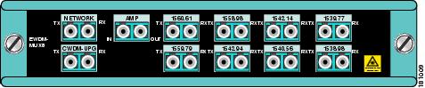
8-Channel Multiplexer/Demultiplexer (EWDM-MUX8=)
The 8-Channel Multiplexer/Demultiplexer (EWDM-MUX8=) allows you to multiplex/demultiplex eight DWDM channels and combine them with up to 8 CWDM channels into one pair of fiber. Dual fiber is used for both the network connection and the transceiver connections. The eight available wavelengths are 1542.94 nm, 1542.14 nm, 1540.56 nm, 1539.77 nm, 1538.98 - 1560.61 nm, 1559.79 nm, and 1558.98 nm. The multiplexer/demultiplexer, shown in Figure 1, is equipped with a port that allows you to connect to the booster amplifier.
Figure 1 Eight Channel Multiplexer/Demultiplexer (EWDM-MUX8=) Front Panel
Table 2 EWDM-MUX8= Channel Plan
|
EWDM Channel ID
|
Wavelength (nm)
|
1 |
1538.98 |
2 |
1539.77 |
3 |
1540.56 |
4 |
1542.14 |
5 |
1542.94 |
6 |
1558.98 |
7 |
1559.79 |
8 |
1560.61 |
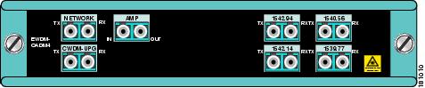
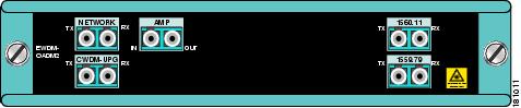
Four-Channel and Two- Channel OADM (EWDM-OADM4= and EWDM-OADM2=)
The four-channel and two-channel OADM (EWDM-OADM4= and EWDM-OADM2=) allows you to respectively add/drop four or two channels (with different wavelengths) and combine them with up to 8 CWDM channels into one pair of fiber. Dual fiber is used for both the network connection and the transceiver connections. The two OADMs, shown in Figure 2 and Figure 3, are equipped with a port that allows you to connect to the booster amplifier and support the following wavelengths:
•EWDM-OADM4—1542.94 nm, 1542.14 nm, 1540.56 nm, 1539.77 nm.
•EWDM-OADM2—1560.61 nm, 1559.79 nm.
Figure 2 Four-channel OADM (EWDM-OADM4=) Front Panel
Table 3 EWDM-OADM4= Channel Plan
|
EWDM Channel ID
|
Wavelength (nm)
|
2 |
1539.77 |
3 |
1540.56 |
4 |
1542.14 |
5 |
1542.94 |
Figure 3 Two-Channel OADM (EWDM-OADM2) Front Panel
Table 4 EWDM-OADM2= Channel Plan
|
EWDM Channel ID
|
Wavelength (nm)
|
7 |
1559.79 |
8 |
1560.61 |
DWDM Booster Amplifier (EWDM-OA=)
The DWDM Booster Amplifier (EWDM-OA=) integrates a 10-GB connection over 1-GB CWDM networks without sacrificing the reach of these networks, and compensates for the power budget gap between the 10-GB DWDM pluggable transceivers and the low speed 1-GB GBIC/SFP. Dual fiber is used for both the network and the transciever connections.
The booster amplifier boosts the signal power and therefore the maximum distance for the 10 GB Ethernet connection.
The booster amplifier modules are equipped with a monitor port that allows you to monitor amplifier conditions and adjust settings.
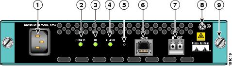
Figure 4 Booster Amplifier (EWDM-OA=) Front Panel
|
1
|
AC inlet |
6
|
RS-232 Management connection |
|
2
|
Power LED |
7
|
LC connector |
|
3
|
In LED |
8
|
Ground |
|
4
|
ALARM LED |
9
|
Captive screw |
|
5
|
Reset button |
|
|
Table 5 explains the meanings for the LEDs on the booster amplifier.
Table 5 Booster Amplifier LED Meanings
|
LED
|
Color
|
Meaning
|
POWER |
Green Red |
Power is good Power failure or under-voltage |
IN |
Green Red |
Input in range Input out of range |
ALARM |
Green Orange Red |
Normal Minor problem Severe problem |
The reset button is used to restart the unit without unplugging it.
The rollover cable needed to connect to the console port is not included. To connect a terminal to the amplifier, use a PC, a rollover cable, and a terminal emulation program with the following settings:
•9600 kbps
•1 stop bit
•8 data bits
•No parity
Table 6 shows the commands available when you connect to the booster amplifier console port.
Table 6 Amplifier Management Commands
|
Command
|
Description
|
Return syntax
|
|
|
Set command line echoing to on or off. If no argument is provided the current setting is displayed. |
|
show [pin | pout |
psig | gain]
|
Displays input power, total output power and signal gain. The Signal power is total power minus the estimated ASE power. |
|
|
|
Displays the status of the pump laser. ILD: laser diode current TEMP: laser diode temperature ITC: TEC current VTC: TEC voltage |
|
show alarm [los |
lop | eip ]
|
Displays loss of signal, loss of power, and excess input power settings for the alarms. |
|
|
|
Provides product identification data. PID is the product identification.
VID is the version identification.
S/N is the Serial Number.
CLEI is the CLEI code. |
INVENTORY PID: ABCD11111111
INVENTORY S/N: ABCD1111111
INVENTORY CLEI: ABCD111111
|
CWDM GBIC and CWDM SFP Transceivers
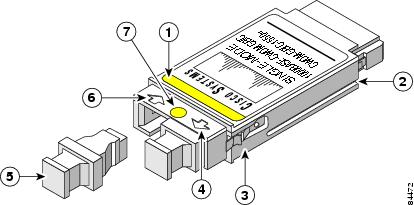
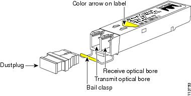
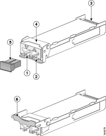
The CWDM GBIC and CWDM SFP transceivers are hot-swappable input/output devices that link your switching module to the CWDM passive optical system using a pair of single-mode fiber-optic cables. The two transceiver types have different form factors and use different fiber-optic cable connectors. Figure 5 shows a CWDM GBIC transceiver which uses an SC connector, and Figure 6 shows a CWDM SFP transceiver which uses an LC connector.
Figure 5 CWDM GBIC
|
1
|
Color label identifying laser wavelength |
5
|
Optical bore dust plug |
|
2
|
Alignment groove |
6
|
Receive optical bore |
|
3
|
Spring clip |
7
|
Color dot identifying laser wavelength |
|
4
|
Transmit optical bore |
|
|
Warning Use of controls, adjustments, or performing procedures other than those specified may result in hazardous radiation exposure. Statement 1057
Figure 6 CWDM SFP
The CWDM GBIC and CWDM SFP transceivers are available in eight wavelengths. (See Table 7.) Each CWDM GBIC and CWDM SFP transceiver is color coded to match the connector colors on the OADM modules.
Table 7 CWDM GBIC and SFP Transceiver Color Codes
|
GBIC Transceiver Product Number
|
SFP Transceiver Product Number
|
Description
|
Connector Color Code
|
CWDM-GBIC-1470= |
CWDM-SFP-1470= |
1000BASE-CWDM, 1470 nm |
Gray |
CWDM-GBIC-1490= |
CWDM-SFP-1490= |
1000BASE-CWDM, 1490 nm |
Violet |
CWDM-GBIC-1510= |
CWDM-SFP-1510= |
1000BASE-CWDM, 1510 nm |
Blue |
CWDM-GBIC-1530= |
CWDM-SFP-1530= |
1000BASE-CWDM, 1530 nm |
Green |
CWDM-GBIC-1550= |
CWDM-SFP-1550= |
1000BASE-CWDM, 1550 nm |
Yellow |
CWDM-GBIC-1570= |
CWDM-SFP-1570= |
1000BASE-CWDM, 1570 nm |
Orange |
CWDM-GBIC-1590= |
CWDM-SFP-1590= |
1000BASE-CWDM, 1590 nm |
Red |
CWDM-GBIC-1610= |
CWDM-SFP-1610= |
1000BASE-CWDM, 1610 nm |
Brown |
For information on installing, removing, and maintaining the CWDM GBIC and SFP transceivers, refer to the Cisco CWDM GBIC and CWDM SFP Installation Note that accompanies the CWDM GBIC and CWDM SFP transceivers.
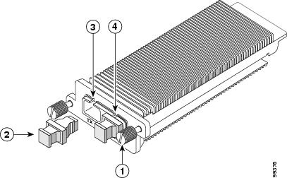
DWDM XENPAK, X2, and XFP Transceivers
The DWDM XENPAK, X2, and XFP transceivers are hot-swappable input-output devices that plug into 10-Gigabit Ethernet ports.
Figure 7 DWDM XENPAK Transceiver Features
|
1
|
Captive installation screw |
3
|
Transmit optical bore |
|
2
|
Optical bore dust plug |
4
|
Receive optical bore |
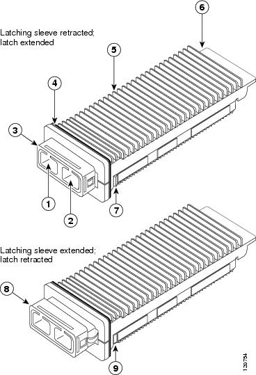
Figure 8 DWDM X2 Transceiver Features
|
1
|
Transmit optical bore |
6
|
Module connector |
|
2
|
Receive optical bore |
7
|
Latch (extended) |
|
3
|
Latching sleeve (retracted) |
8
|
Latching sleeve (extended) |
|
4
|
EMI gasket |
9
|
Latch (retracted) |
|
5
|
Transceiver heat sink |
|
|
Figure 9 DWDM XFP Transceiver Features
|
1
|
Transmit optical bore |
4
|
bail clasp (locked position) |
|
2
|
Receive optical bore |
5
|
Dust plug |
|
3
|
Transceiver socket connector |
6
|
bail clasp (unlocked position) |
Table 8, Table 9, and Table 10 list the respective product numbers for DWDM XENPAK, X2, and XFP transceivers depending on the desired band or channel.
Table 8 DWDM XENPAK Transceiver Module Product Numbers
|
Product Number
|
Description
|
ITU Channel
|
DWDM-XENPAK-60.61= |
10GBASE-DWDM 1560.61 nm XENPAK (100-GHz ITU grid) |
21 |
DWDM-XENPAK-59.79= |
10GBASE-DWDM 1559.79 nm XENPAK (100-GHz ITU grid) |
22 |
DWDM-XENPAK-58.98= |
10GBASE-DWDM 1558.98 nm XENPAK (100-GHz ITU grid) |
23 |
DWDM-XENPAK-58.17= |
10GBASE-DWDM 1558.17 nm XENPAK (100-GHz ITU grid) |
24 |
DWDM-XENPAK-56.55= |
10GBASE-DWDM 1556.55 nm XENPAK (100-GHz ITU grid) |
26 |
DWDM-XENPAK-55.75= |
10GBASE-DWDM 1555.75 nm XENPAK (100-GHz ITU grid) |
27 |
DWDM-XENPAK-54.94= |
10GBASE-DWDM 1554.94 nm XENPAK (100-GHz ITU grid) |
28 |
DWDM-XENPAK-54.13= |
10GBASE-DWDM 1554.13 nm XENPAK (100-GHz ITU grid) |
29 |
DWDM-XENPAK-52.52= |
10GBASE-DWDM 1552.52 nm XENPAK (100-GHz ITU grid) |
31 |
DWDM-XENPAK-51.72= |
10GBASE-DWDM 1551.72 nm XENPAK (100-GHz ITU grid) |
32 |
DWDM-XENPAK-50.92= |
10GBASE-DWDM 1550.92 nm XENPAK (100-GHz ITU grid) |
33 |
DWDM-XENPAK-50.12= |
10GBASE-DWDM 1550.12 nm XENPAK (100-GHz ITU grid) |
34 |
DWDM-XENPAK-48.51= |
10GBASE-DWDM 1548.51 nm XENPAK (100-GHz ITU grid) |
36 |
DWDM-XENPAK-47.72= |
10GBASE-DWDM 1547.72 nm XENPAK (100-GHz ITU grid) |
37 |
DWDM-XENPAK-46.92= |
10GBASE-DWDM 1546.92 nm XENPAK (100-GHz ITU grid) |
38 |
DWDM-XENPAK-46.12= |
10GBASE-DWDM 1546.12 nm XENPAK (100-GHz ITU grid) |
39 |
DWDM-XENPAK-44.53= |
10GBASE-DWDM 1544.53 nm XENPAK (100-GHz ITU grid) |
41 |
DWDM-XENPAK-43.73= |
10GBASE-DWDM 1543.73 nm XENPAK (100-GHz ITU grid) |
42 |
DWDM-XENPAK-42.94= |
10GBASE-DWDM 1542.94 nm XENPAK (100-GHz ITU grid) |
43 |
DWDM-XENPAK-42.14= |
10GBASE-DWDM 1542.14 nm XENPAK (100-GHz ITU grid) |
44 |
DWDM-XENPAK-40.56= |
10GBASE-DWDM 1540.56 nm XENPAK (100-GHz ITU grid) |
46 |
DWDM-XENPAK-39.77= |
10GBASE-DWDM 1539.77 nm XENPAK (100-GHz ITU grid) |
47 |
DWDM-XENPAK-38.98= |
10GBASE-DWDM 1538.98 nm XENPAK (100-GHz ITU grid) |
48 |
DWDM-XENPAK-38.19= |
10GBASE-DWDM 1538.19 nm XENPAK (100-GHz ITU grid) |
49 |
DWDM-XENPAK-36.61= |
10GBASE-DWDM 1536.61 nm XENPAK (100-GHz ITU grid) |
51 |
DWDM-XENPAK-35.82= |
10GBASE-DWDM 1535.82 nm XENPAK (100-GHz ITU grid) |
52 |
DWDM-XENPAK-35.04= |
10GBASE-DWDM 1535.04 nm XENPAK (100-GHz ITU grid) |
53 |
DWDM-XENPAK-34.25= |
10GBASE-DWDM 1534.25 nm XENPAK (100-GHz ITU grid) |
54 |
DWDM-XENPAK-32.68= |
10GBASE-DWDM 1532.68 nm XENPAK (100-GHz ITU grid) |
56 |
DWDM-XENPAK-31.90= |
10GBASE-DWDM 1531.90 nm XENPAK (100-GHz ITU grid) |
57 |
DWDM-XENPAK-31.12= |
10GBASE-DWDM 1531.12 nm XENPAK (100-GHz ITU grid) |
58 |
DWDM-XENPAK-30.33= |
10GBASE-DWDM 1530.33 nm XENPAK (100-GHz ITU grid) |
59 |
Table 9 DWDM X2 Transceiver Module Product Numbers
|
Product Number
|
Description
|
ITU Channel
|
DWDM-X2-60.61= |
10GBASE-DWDM 1560.61 nm X2 (100-GHz ITU grid) |
21 |
DWDM-X2-59.79= |
10GBASE-DWDM 1559.79 nm X2 (100-GHz ITU grid) |
22 |
DWDM-X2-58.98= |
10GBASE-DWDM 1558.98 nm X2 (100-GHz ITU grid) |
23 |
DWDM-X2-58.17= |
10GBASE-DWDM 1558.17 nm X2 (100-GHz ITU grid) |
24 |
DWDM-X2-56.55= |
10GBASE-DWDM 1556.55 nm X2 (100-GHz ITU grid) |
26 |
DWDM-X2-55.75= |
10GBASE-DWDM 1555.75 nm X2 (100-GHz ITU grid) |
27 |
DWDM-X2-54.94= |
10GBASE-DWDM 1554.94 nm X2 (100-GHz ITU grid) |
28 |
DWDM-X2-54.13= |
10GBASE-DWDM 1554.13 nm X2 (100-GHz ITU grid) |
29 |
DWDM-X2-52.52= |
10GBASE-DWDM 1552.52 nm X2 (100-GHz ITU grid) |
31 |
DWDM-X2-51.72= |
10GBASE-DWDM 1551.72 nm X2 (100-GHz ITU grid) |
32 |
DWDM-X2-50.92= |
10GBASE-DWDM 1550.92 nm X2 (100-GHz ITU grid) |
33 |
DWDM-X2-50.12= |
10GBASE-DWDM 1550.12 nm X2 (100-GHz ITU grid) |
34 |
DWDM-X2-48.51= |
10GBASE-DWDM 1548.51 nm X2 (100-GHz ITU grid) |
36 |
DWDM-X2-47.72= |
10GBASE-DWDM 1547.72 nm X2 (100-GHz ITU grid) |
37 |
DWDM-X2-46.92= |
10GBASE-DWDM 1546.92 nm X2 (100-GHz ITU grid) |
38 |
DWDM-X2-46.12= |
10GBASE-DWDM 1546.12 nm X2 (100-GHz ITU grid) |
39 |
DWDM-X2-44.53= |
10GBASE-DWDM 1544.53 nm X2 (100-GHz ITU grid) |
41 |
DWDM-X2-43.73= |
10GBASE-DWDM 1543.73 nm X2 (100-GHz ITU grid) |
42 |
DWDM-X2-42.94= |
10GBASE-DWDM 1542.94 nm X2 (100-GHz ITU grid) |
43 |
DWDM-X2-42.14= |
10GBASE-DWDM 1542.14 nm X2 (100-GHz ITU grid) |
44 |
DWDM-X2-40.56= |
10GBASE-DWDM 1540.56 nm X2 (100-GHz ITU grid) |
46 |
DWDM-X2-39.77= |
10GBASE-DWDM 1539.77 nm X2 (100-GHz ITU grid) |
47 |
DWDM-X2-38.98= |
10GBASE-DWDM 1538.98 nm X2 (100-GHz ITU grid) |
48 |
DWDM-X2-38.19= |
10GBASE-DWDM 1538.19 nm X2 (100-GHz ITU grid) |
49 |
DWDM-X2-36.61= |
10GBASE-DWDM 1536.61 nm X2 (100-GHz ITU grid) |
51 |
DWDM-X2-35.82= |
10GBASE-DWDM 1535.82 nm X2 (100-GHz ITU grid) |
52 |
DWDM-X2-35.04= |
10GBASE-DWDM 1535.04 nm X2 (100-GHz ITU grid) |
53 |
DWDM-X2-34.25= |
10GBASE-DWDM 1534.25 nm X2 (100-GHz ITU grid) |
54 |
DWDM-X2-32.68= |
10GBASE-DWDM 1532.68 nm X2 (100-GHz ITU grid) |
56 |
DWDM-X2-31.90= |
10GBASE-DWDM 1531.90 nm X2 (100-GHz ITU grid) |
57 |
DWDM-X2-31.12= |
10GBASE-DWDM 1531.12 nm X2 (100-GHz ITU grid) |
58 |
DWDM-X2-30.33= |
10GBASE-DWDM 1530.33 nm X2 (100-GHz ITU grid) |
59 |
Table 10 DWDM XFP Transceiver Module Product Numbers
|
Transceiver Module Product Number
|
Description
|
ITU Channel
|
DWDM-XFP-60.61= |
10GBASE-DWDM 1560.61 nm XFP (100-GHz ITU grid) |
21 |
DWDM-XFP-59.79= |
10GBASE-DWDM 1559.79 nm XFP (100-GHz ITU grid) |
22 |
DWDM-XFP-58.98= |
10GBASE-DWDM 1558.98 nm XFP (100-GHz ITU grid) |
23 |
DWDM-XFP-58.17= |
10GBASE-DWDM 1558.17 nm XFP (100-GHz ITU grid) |
24 |
DWDM-XFP-56.55= |
10GBASE-DWDM 1556.55 nm XFP (100-GHz ITU grid) |
26 |
DWDM-XFP-55.75= |
10GBASE-DWDM 1555.75 nm XFP (100-GHz ITU grid) |
27 |
DWDM-XFP-54.94= |
10GBASE-DWDM 1554.94 nm XFP (100-GHz ITU grid) |
28 |
DWDM-XFP-54.13= |
10GBASE-DWDM 1554.13 nm XFP (100-GHz ITU grid) |
29 |
DWDM-XFP-52.52= |
10GBASE-DWDM 1552.52 nm XFP (100-GHz ITU grid) |
31 |
DWDM-XFP-51.72= |
10GBASE-DWDM 1551.72 nm XFP (100-GHz ITU grid) |
32 |
DWDM-XFP-50.92= |
10GBASE-DWDM 1550.92 nm XFP (100-GHz ITU grid) |
33 |
DWDM-XFP-50.12= |
10GBASE-DWDM 1550.12 nm XFP (100-GHz ITU grid) |
34 |
DWDM-XFP-48.51= |
10GBASE-DWDM 1548.51 nm XFP (100-GHz ITU grid) |
36 |
DWDM-XFP-47.72= |
10GBASE-DWDM 1547.72 nm XFP (100-GHz ITU grid) |
37 |
DWDM-XFP-46.92= |
10GBASE-DWDM 1546.92 nm XFP (100-GHz ITU grid) |
38 |
DWDM-XFP-46.12= |
10GBASE-DWDM 1546.12 nm XFP (100-GHz ITU grid) |
39 |
DWDM-XFP-44.53= |
10GBASE-DWDM 1544.53 nm XFP (100-GHz ITU grid) |
41 |
DWDM-XFP-43.73= |
10GBASE-DWDM 1543.73 nm XFP (100-GHz ITU grid) |
42 |
DWDM-XFP-42.94= |
10GBASE-DWDM 1542.94 nm XFP (100-GHz ITU grid) |
43 |
DWDM-XFP-42.14= |
10GBASE-DWDM 1542.14 nm XFP (100-GHz ITU grid) |
44 |
DWDM-XFP-40.56= |
10GBASE-DWDM 1540.56 nm XFP (100-GHz ITU grid) |
46 |
DWDM-XFP-39.77= |
10GBASE-DWDM 1539.77 nm XFP (100-GHz ITU grid) |
47 |
DWDM-XFP-38.98= |
10GBASE-DWDM 1538.98 nm XFP (100-GHz ITU grid) |
48 |
DWDM-XFP-38.19= |
10GBASE-DWDM 1538.19 nm XFP (100-GHz ITU grid) |
49 |
DWDM-XFP-36.61= |
10GBASE-DWDM 1536.61 nm XFP (100-GHz ITU grid) |
51 |
DWDM-XFP-35.82= |
10GBASE-DWDM 1535.82 nm XFP (100-GHz ITU grid) |
52 |
DWDM-XFP-35.04= |
10GBASE-DWDM 1535.04 nm XFP (100-GHz ITU grid) |
53 |
DWDM-XFP-34.25= |
10GBASE-DWDM 1534.25 nm XFP (100-GHz ITU grid) |
54 |
DWDM-XFP-32.68= |
10GBASE-DWDM 1532.68 nm XFP (100-GHz ITU grid) |
56 |
DWDM-XFP-31.90= |
10GBASE-DWDM 1531.90 nm XFP (100-GHz ITU grid) |
57 |
DWDM-XFP-31.12= |
10GBASE-DWDM 1531.12 nm XFP (100-GHz ITU grid) |
58 |
DWDM-XFP-30.33= |
10GBASE-DWDM 1530.33 nm XFP (100-GHz ITU grid) |
59 |
Safety Overview
Throughout this publication, safety warnings appear in procedures that, if performed incorrectly, can harm you. A warning symbol precedes each warning statement.
Statement 1071—Warning Definition
|
Warning |
IMPORTANT SAFETY INSTRUCTIONS This warning symbol means danger. You are in a situation that could cause bodily injury. Before you work on any equipment, be aware of the hazards involved with electrical circuitry and be familiar with standard practices for preventing accidents. Use the statement number provided at the end of each warning to locate its translation in the translated safety warnings that accompanied this device. SAVE THESE INSTRUCTIONS |
Waarschuwing |
BELANGRIJKE VEILIGHEIDSINSTRUCTIES Dit waarschuwingssymbool betekent gevaar. U verkeert in een situatie die lichamelijk letsel kan veroorzaken. Voordat u aan enige apparatuur gaat werken, dient u zich bewust te zijn van de bij elektrische schakelingen betrokken risico's en dient u op de hoogte te zijn van de standaard praktijken om ongelukken te voorkomen. Gebruik het nummer van de verklaring onderaan de waarschuwing als u een vertaling van de waarschuwing die bij het apparaat wordt geleverd, wilt raadplegen. BEWAAR DEZE INSTRUCTIES |
Varoitus |
TÄRKEITÄ TURVALLISUUSOHJEITA Tämä varoitusmerkki merkitsee vaaraa. Tilanne voi aiheuttaa ruumiillisia vammoja. Ennen kuin käsittelet laitteistoa, huomioi sähköpiirien käsittelemiseen liittyvät riskit ja tutustu onnettomuuksien yleisiin ehkäisytapoihin. Turvallisuusvaroitusten käännökset löytyvät laitteen mukana toimitettujen käännettyjen turvallisuusvaroitusten joukosta varoitusten lopussa näkyvien lausuntonumeroiden avulla. SÄILYTÄ NÄMÄ OHJEET |
Attention |
IMPORTANTES INFORMATIONS DE SÉCURITÉ Ce symbole d'avertissement indique un danger. Vous vous trouvez dans une situation pouvant entraîner des blessures ou des dommages corporels. Avant de travailler sur un équipement, soyez conscient des dangers liés aux circuits électriques et familiarisez-vous avec les procédures couramment utilisées pour éviter les accidents. Pour prendre connaissance des traductions des avertissements figurant dans les consignes de sécurité traduites qui accompagnent cet appareil, référez-vous au numéro de l'instruction situé à la fin de chaque avertissement. CONSERVEZ CES INFORMATIONS |
Warnung |
WICHTIGE SICHERHEITSHINWEISE Dieses Warnsymbol bedeutet Gefahr. Sie befinden sich in einer Situation, die zu Verletzungen führen kann. Machen Sie sich vor der Arbeit mit Geräten mit den Gefahren elektrischer Schaltungen und den üblichen Verfahren zur Vorbeugung vor Unfällen vertraut. Suchen Sie mit der am Ende jeder Warnung angegebenen Anweisungsnummer nach der jeweiligen Übersetzung in den übersetzten Sicherheitshinweisen, die zusammen mit diesem Gerät ausgeliefert wurden. BEWAHREN SIE DIESE HINWEISE GUT AUF. |
Avvertenza |
IMPORTANTI ISTRUZIONI SULLA SICUREZZA Questo simbolo di avvertenza indica un pericolo. La situazione potrebbe causare infortuni alle persone. Prima di intervenire su qualsiasi apparecchiatura, occorre essere al corrente dei pericoli relativi ai circuiti elettrici e conoscere le procedure standard per la prevenzione di incidenti. Utilizzare il numero di istruzione presente alla fine di ciascuna avvertenza per individuare le traduzioni delle avvertenze riportate in questo documento. CONSERVARE QUESTE ISTRUZIONI |
Advarsel |
VIKTIGE SIKKERHETSINSTRUKSJONER Dette advarselssymbolet betyr fare. Du er i en situasjon som kan føre til skade på person. Før du begynner å arbeide med noe av utstyret, må du være oppmerksom på farene forbundet med elektriske kretser, og kjenne til standardprosedyrer for å forhindre ulykker. Bruk nummeret i slutten av hver advarsel for å finne oversettelsen i de oversatte sikkerhetsadvarslene som fulgte med denne enheten. TA VARE PÅ DISSE INSTRUKSJONENE |
Aviso |
INSTRUÇÕES IMPORTANTES DE SEGURANÇA Este símbolo de aviso significa perigo. Você está em uma situação que poderá ser causadora de lesões corporais. Antes de iniciar a utilização de qualquer equipamento, tenha conhecimento dos perigos envolvidos no manuseio de circuitos elétricos e familiarize-se com as práticas habituais de prevenção de acidentes. Utilize o número da instrução fornecido ao final de cada aviso para localizar sua tradução nos avisos de segurança traduzidos que acompanham este dispositivo. GUARDE ESTAS INSTRUÇÕES |
¡Advertencia! |
INSTRUCCIONES IMPORTANTES DE SEGURIDAD Este símbolo de aviso indica peligro. Existe riesgo para su integridad física. Antes de manipular cualquier equipo, considere los riesgos de la corriente eléctrica y familiarícese con los procedimientos estándar de prevención de accidentes. Al final de cada advertencia encontrará el número que le ayudará a encontrar el texto traducido en el apartado de traducciones que acompaña a este dispositivo. GUARDE ESTAS INSTRUCCIONES |
Varning! |
VIKTIGA SÄKERHETSANVISNINGAR Denna varningssignal signalerar fara. Du befinner dig i en situation som kan leda till personskada. Innan du utför arbete på någon utrustning måste du vara medveten om farorna med elkretsar och känna till vanliga förfaranden för att förebygga olyckor. Använd det nummer som finns i slutet av varje varning för att hitta dess översättning i de översatta säkerhetsvarningar som medföljer denna anordning. SPARA DESSA ANVISNINGAR |
|
|
|
|
|
|
|
|
|
|
Aviso |
INSTRUÇÕES IMPORTANTES DE SEGURANÇA Este símbolo de aviso significa perigo. Você se encontra em uma situação em que há risco de lesões corporais. Antes de trabalhar com qualquer equipamento, esteja ciente dos riscos que envolvem os circuitos elétricos e familiarize-se com as práticas padrão de prevenção de acidentes. Use o número da declaração fornecido ao final de cada aviso para localizar sua tradução nos avisos de segurança traduzidos que acompanham o dispositivo. GUARDE ESTAS INSTRUÇÕES |
Advarsel |
VIGTIGE SIKKERHEDSANVISNINGER Dette advarselssymbol betyder fare. Du befinder dig i en situation med risiko for legemesbeskadigelse. Før du begynder arbejde på udstyr, skal du være opmærksom på de involverede risici, der er ved elektriske kredsløb, og du skal sætte dig ind i standardprocedurer til undgåelse af ulykker. Brug erklæringsnummeret efter hver advarsel for at finde oversættelsen i de oversatte advarsler, der fulgte med denne enhed. GEM DISSE ANVISNINGER |
|
|
|
|
|
|
|
|
|
|
|
|
|
|
|
|

Warning Only trained and qualified personnel should be allowed to install, replace, or service this equipment. Statement 1030
Warning Ultimate disposal of this product should be handled according to all national laws and regulations. Statement 1040
Warning Class I (CDRH) and Class 1M (IEC) laser products. Statement 1055
Warning Use of controls, adjustments, or performing procedures other than those specified may result in hazardous radiation exposure. Statement 1057
Note The maximum output is less than 10 mW when measured through a 3.5-mm aperture located at a distance of 100 mm and the wavelength is 1470-nm to 1610-nm from the multichannel MUX or OADM module output connectors. Other fiber-optic ports have been tested and comply with the Class 1 limits of IEC 60825-1 and Class 1 limits of 21 CFR 1040.10 (with considerations pursuant to FDA Laser Notice 50, dated July 26, 2001).
Installing the EWDM Passive Optical System
The following sections provide installation procedures for the EWDM passive optical system components:
•Required Tools
•Installing the Two-Slot Chassis (CWDM-CHASSIS-2=)
•Installing the EWDM OADM Modules or Booster Amplifier
•Removing the EWDM OADM Module or Booster Amplifier
•Installing and Removing Transceivers
Required Tools
You will need these tools to install the EWDM passive optical system:
•Number 2 Phillips screwdriver for the 10-32 or the 12-24 chassis installation screws.
•Wrist strap or other personal grounding device to prevent damage from electrostatic discharge.
•Antistatic mat or antistatic foam to set the equipment on.
•Fiber-optic end-face cleaning tools and inspection equipment. For complete information on inspecting and cleaning fiber-optic connections, refer to the white-paper document at this URL:
http://www.cisco.com/en/US/tech/tk482/tk876/technologies_white_paper09186a0080254eba.shtml
•Level (optional)
•Tape measure (optional)
Installing the Two-Slot Chassis (CWDM-CHASSIS-2=)
Note Ensure that you install the two-slot chassis in the same rack or an adjacent rack to your system so that you can connect all the cables between your OADM modules and the transceivers in your system.
Caution
When performing the following procedures, wear a grounding strap to prevent damage from electrostatic discharge to the OADM module. Some platforms have an ESD connector for attaching the wrist strap.
To mount the two-slot chassis in an equipment rack, follow these steps:
Step 1 Remove the two-slot chassis from the shipping packaging.
Step 2 Position the two-slot chassis in the rack where you are going to install it. Align the mounting holes in the chassis L brackets with the mounting holes in the equipment rack to ensure that the two-slot chassis is mounted straight and level. Use a level or tape measure to verify that the chassis is positioned level in the rack.
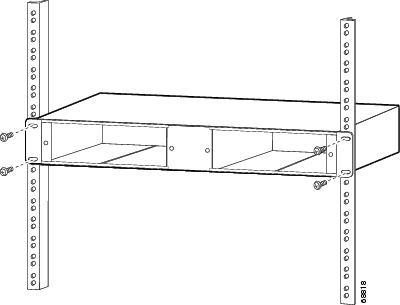
Step 3 Secure the two-slot chassis using four (two per side) 12-24 x 3/4-inch screws or four 10-32 x 3/4-inch screws. Thread the screws through the elongated holes in the L bracket and into the threaded holes in the mounting post. (See Figure 10.)
Figure 10 Mounting the Two-slot Chassis in the Rack
Installing the EWDM OADM Modules or Booster Amplifier
Caution
When performing the following procedures, wear a grounding strap to avoid ESD damage to the OADM module. Make sure the other end of the ground strap is securely attached to a grounded point.
To install the EWDM OADM modules or booster amplifier, follow these steps:
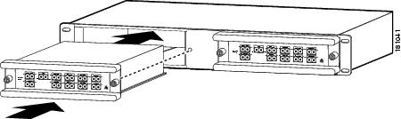
Step 1 Align the EWDM OADM module or booster amplifier with the slot on the two-slot chassis. (See Figure 11.)
Figure 11 Installing an EWDM OADM Module (EWDM-MUX8= shown)
Step 2 Gently push the OADM module or booster amplifier into the two-slot chassis. Ensure that you line up the captive screws on the OADM module or booster amplifier with the screw holes on the two-slot chassis.
Note You may have CWDM and EWDM optical modules in the same chassis.
Step 3 Tighten the two captive screws with the Number 2 Phillips screwdriver. Do not overtighten.
Step 4 Do not remove the optical bore dust plugs at this time.
Step 5 If you are installing a MUX or OADM and will not be using it with a booster amplifier, connect the AMP IN to the AMP OUT port of the EWDM module.
Figure 12 Installing the Jumper
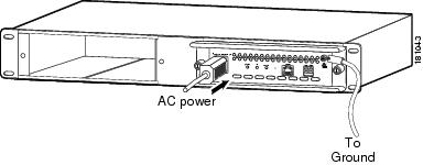
Step 6 If you are installing a booster amplifier, connect the grounding screw to earth ground as appropriate for your facility. Consult an electrician if necessary, grounding should comply with local codes. (See Figure 13.)
Step 7 If you are installing a booster amplifier, connect the power cord. (See Figure 13.)
Figure 13 Power and Grounding (Booster Amplifier only)
Removing the EWDM OADM Module or Booster Amplifier
Caution
When performing the following procedures, wear a grounding strap to avoid ESD damage to the OADM module.
To remove the OADM module or the multiplexer/demultiplexer module or booster amplifier, follow these steps:
Step 1 Disconnect all network interface cables from the OADM module or booster amplifier and immediately install dust plugs in the network interface cable connectors and the OADM connectors.
Step 2 (Amplifier only) Disconnect the power and ground cables from the booster amplifier.
Step 3 Loosen the captive screw on each side of the OADM module or booster amplifier using a Phillips screwdriver.
Step 4 Gently pull on both captive screws to release the OADM module or booster amplifier from the two-slot chassis.
Step 5 Pull the OADM module or booster amplifier out of the two-slot chassis, and place it on an antistatic mat or antistatic foam pad.
Installing and Removing Transceivers
For information on installing, removing, and maintaining the transceivers, refer to:
http://www.cisco.com/en/US/products/hw/modules/ps5455/prod_installation_guides_list.html
Caution
Transceivers are static-sensitive devices. Always use an ESD wrist strap or similar individual grounding device when handling or coming in contact with transceivers.
Note To prevent contamination, do not remove the optical bore dust plugs from the transceivers until directed to do so.
Connecting the EWDM Passive Optical System to Your System
This section is divided into the following topics:
•Connecting Cables for a Passive Application
•Connecting Cables for a Boosted Application
Note Use the EWDM passive optical system connector color codes shown in Table 7 to help you connect the EWDM passive optical system to your system.
See Figures 2 through 5 for the OADM and multiplexer/demultiplexer module front panels.
Warning Class 1M laser radiation when open. Do not view directly with optical instruments. Statement 1053
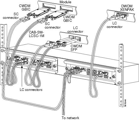
Connecting Cables for a Passive Application
Note Make sure that the CWDM GBIC transceiver color code or CWDM SFP transceiver color code matches the color code of the CWDM OADM port to which it is connected, and make sure that the DWDM transceiver wavelength matches the wavelength label of the EWDM OADM port.
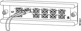
To connect cables for a non- boosted application, follow these steps (see Figure 14):
Step 1 Insert the transceivers into the appropriate modules on your switch or router system if you have not already done so.
Note Clean all fiber-optic plugs on the cables before inserting the plugs into the fiber-optic connectors.
Note Always use single-mode fiber-optic patch cables to connect the OADM ports to the transceivers.
Warning Invisible laser radiation may be emitted from the end of the unterminated fiber cable or connector. Do not view directly with optical instruments. Viewing the laser output with certain optical instruments (for example, eye loupes, magnifiers, and microscopes) within a distance of 100 mm may pose an eye hazard. Statement 1056
Figure 14 Cabling a Passive Application
Note Before removing the dust plugs and making any optical connections, observe the following guidelines:
–Always keep the protective dust plugs on the unplugged fiber-optic cable connectors and the transceiver optical bores until you are ready to make a connection.
–Always inspect and clean the connector end-faces just before making any connections. Refer to the Tip on this page for a pointer to a fiber-optic inspection and cleaning white paper.
–Always grasp the connector housing to plug or unplug a fiber-optic cable.
Step 2 Remove the dust plugs from the network interface cable connector and the transceiver optical bore. Save the dust plugs for future use.
Step 3 Inspect and clean the connector's fiber-optic end-faces. Refer to the Tip below for a pointer to the fiber-optic inspection and cleaning white paper.
Tip For complete information on inspecting and cleaning fiber-optic connections, refer to the white-paper document at this URL:
http://www.cisco.com/en/US/tech/tk482/tk607/technologies_white_paper09186a0080254eba.shtml
Step 4 Connect the single pair fiber-optic cables from the CWDM GBIC transceivers or CWDM SFP transceivers (Tx/Rx; up to eight channels) to the multiplexer/demultiplexer module equipment connectors (Tx/Rx; up to eight wavelengths). An eight-channel, four-channel, or one-channel OADM or Mux/demux may be used depending on your needs.
Note Connect the Tx ports to the Rx ports and the Rx ports to the Tx ports to ensure that the system operates correctly.
Step 5 Connect the single pair fiber-optic cables from the DWDM transceivers (Tx/Rx; up to eight channels) to the 8-channel multiplexer/demultiplexer module equipment connectors (Tx/Rx; up to eight wavelengths).
Step 6 Connect the NETWORK port on the CWDM passive module to the CWDM UPG port on the EWDM OADM module.
Step 7 Connect the network backbone single pair fiber-optic cable to the multiplexer/demultiplexer NETWORK connector on the EWDM OADM module.
Step 8 Connect the AMP IN and AMP OUT ports of the EWDM module if you have not already done so.
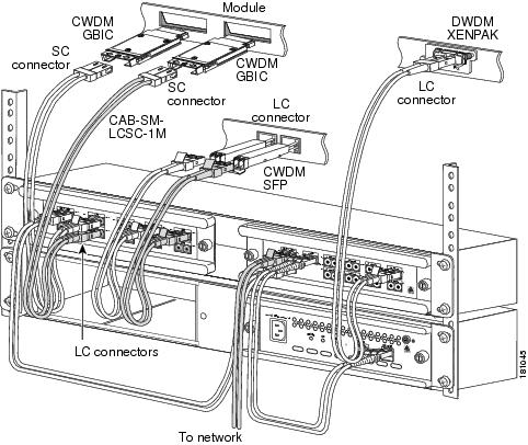
Connecting Cables for a Boosted Application
Note Make sure that the CWDM GBIC transceiver color code or CWDM SFP transceiver color code matches the color code of the CWDM OADM port to which it is connected, and make sure that the DWDM transceiver wavelength matches the wavelength label of the EWDM OADM port.
To connect cables for a boosted application, follow these steps (see Figure 14):
Step 1 Insert the transceivers into the appropriate modules on your switch or router system if you have not already done so.
Note Clean all fiber-optic plugs on the cables before inserting the plugs into the fiber-optic connectors.
Note Always use single-mode fiber-optic patch cables to connect the OADM ports to the transceivers.
Warning Invisible laser radiation may be emitted from the end of the unterminated fiber cable or connector. Do not view directly with optical instruments. Viewing the laser output with certain optical instruments (for example, eye loupes, magnifiers, and microscopes) within a distance of 100 mm may pose an eye hazard. Statement 1056
Figure 15 Cabling a Boosted Application
Note Before removing the dust plugs and making any optical connections, observe the following guidelines:
–Always keep the protective dust plugs on the unplugged fiber-optic cable connectors and the transceiver optical bores until you are ready to make a connection.
–Always inspect and clean the connector end-faces just before making any connections. Refer to the Tip on this page for a pointer to a fiber-optic inspection and cleaning white paper.
–Always grasp the connector housing to plug or unplug a fiber-optic cable.
Step 2 Remove the dust plugs from the network interface cable connector and the transceiver optical bore. Save the dust plugs for future use.
Step 3 Inspect and clean the connector's fiber-optic end-faces. Refer to the Tip below for a pointer to the fiber-optic inspection and cleaning white paper.
Tip For complete information on inspecting and cleaning fiber-optic connections, refer to the white-paper document at this URL:
http://www.cisco.com/en/US/tech/tk482/tk876/technologies_white_paper09186a0080254eba.shtml
Step 4 Connect the single pair fiber-optic cables from the CWDM GBIC transceivers or CWDM SFP transceivers (Tx/Rx; up to eight channels) to the multiplexer/demultiplexer module equipment connectors (Tx/Rx; up to eight wavelengths). An eight-channel, four-channel, or one-channel OADM or Mux/demux may be used depending on your needs.
Note Connect the Tx ports to the Rx ports and the Rx ports to the Tx ports to ensure that the system operates correctly.
Step 5 Connect the single pair fiber-optic cables from the DWDM transceivers (Tx/Rx; up to eight channels) to the 8-channel multiplexer/demultiplexer module equipment connectors (Tx/Rx; up to eight wavelengths).
Step 6 Connect the NETWORK port on the CWDM passive module to the CWDM UPG port on the EWDM OADM module.
Step 7 Connect the network backbone single pair fiber-optic cable to the multiplexer/demultiplexer NETWORK connector on the EWDM OADM module.
Step 8 Connect the AMP IN port on the EWDM OADM module to the IN optical port on the booster amplifier and the AMP OUT port on the EWDM OADM module to the OUT optical port of the booster amplifier.
Specifications
Table 11 lists the environmental specifications for the EWDM OADM and multiplexer/demultiplexer modules. Table 12 lists the optical specifications for the EWDM OADM and multiplexer/demultiplexer modules. Table 13 lists the optical specification for the booster amplifier module.
Table 11 CWDM Passives Physical and Environmental Specifications
|
Item
|
Specification
|
|
Physical Characteristics
|
|
Dimensions |
8.35 x 1.75 x 8.7 in. (212 x 44 x 221 mm) |
Weight |
1.5 lbs. (0.68 kg) |
|
Environmental
|
|
Operating temperature |
23 to 131 ºF (-5 ~ 55ºC) |
Storage temperature |
-40 to 185ºF (-40 to 85ºC) |
Operating Humidity |
5 to 95% |
Table 12 EWDM OADM and Multiplexer/Demultiplexer Module Optical Specifications
|
Device
|
Path
|
Value
|
|
EWDM-MUX8A=
|
|
|
Operating Band |
|
1460-1620 nm |
Channel Spacing |
|
100 GHz |
DWDM channels |
|
1 to 8 |
DWDM channel
0.5 dB bandwidth |
|
-0.12 to 0.12 nm |
Insertion Loss |
Mux DWDM (channel) Demux DWDM (channel) Mux CWDM (band) Demux CWDM (band) Combined Mux Demux DWDM
(same channel) |
3.5 dB (max) 2.5 dB (max) 1 dB (max) 1.5 dB (max) 4.7 dB (max) |
Isolation |
Pass Port Isolation (In band Isolation) Adjacent channels Isolation
(DWDM Channels over DWDM or CWDM channels) |
15 dB mux (min.) 30 dB demux (min.) 30 dB (min.) |
Return Loss |
|
45 dB (min.) |
Directivity |
|
50 dB (min.) |
PDL |
All Paths |
0.2 dB |
PMD |
All Paths |
0.2 ps |
Optical loss Uniformity |
|
1.5 dB |
Max Optical Input Power |
|
300 mW |
|
EWDM-OADM4=
|
|
|
Operating Band |
|
1460-1620 nm |
Channel Spacing |
|
100 GHz |
DWDM channels |
|
2 to 5 |
DWDM channel
0.5 dB bandwidth |
|
-0.12 to 0.12 nm |
Insertion Loss |
Mux DWDM (channel) Demux DWDM (channel) Mux CWDM (band) Demux CWDM (band) Combined Mux Demux DWDM
(same channel) |
2.5 dB (max) 2.5 dB (max) 1 dB (max) 1 dB (max) 3.7 dB (max) |
Isolation |
Pass Port Isolation (In band Isolation) Adjacent channels Isolation
(DWDM Channels over DWDM or CWDM channels) |
15 dB mux (min.) 30 dB demux (min.) 30 dB (min.) |
Return Loss |
|
45 dB (min.) |
Directivity |
|
50 dB (min.) |
PDL |
All Paths |
0.2 dB |
PMD |
All Paths |
0.2 ps |
Optical loss Uniformity |
|
1.5 dB |
Max Optical Input Power |
|
300 mW |
|
EWDM-OADM2=
|
|
|
Operating Band |
|
1460-1620 nm |
Channel Spacing |
|
100 GHz |
DWDM channels |
|
7, 8 |
DWDM channel
0.5 dB bandwidth |
|
-0.12 to 0.12 nm |
Insertion Loss |
Mux DWDM (channel) Demux DWDM (channel) Mux CWDM (band) Demux CWDM (band) Combined Mux Demux DWDM
(same channel) |
2 dB (max) 2 dB (max) 1 dB (max) 1 dB (max) 3.1 dB (max) |
Isolation |
Pass Port Isolation (In band Isolation) Adjacent channels Isolation
(DWDM Channels over DWDM or CWDM channels) |
15 dB mux (min.) 30 dB demux (min.) 30 dB (min.) |
Return Loss |
|
45 dB (min.) |
Directivity |
|
50 dB (min.) |
PDL |
All Paths |
0.2 dB |
PMD |
All Paths |
0.2 ps |
Optical loss Uniformity |
|
1 dB |
Max Optical Input Power |
|
300 mW |
Table 13 DWDM Booster Amplifier Optical Specifications
|
Parameter
|
Specification
|
Total operating signal wavelength range |
1538.2 to 1561.4 nm |
Total output power |
17.5 dBm (max) |
Total input power |
-4.5 to 9.5 dBm |
Per channel input power |
-4.5 to 2.5 dBm |
Single channel output power
(In Gain control mode) |
3.5 to 12 dBm |
Optimal Flat Gain |
8dB typical |
Gain Flatness (@nominal Gain) |
-0.5 to +0.5 dB |
Noise Figure |
10 dB |
Return loss |
40 dB |
PDG |
-0.25 to +0.25 dB |
PMD |
0.3 Ps |
Translated Safety Warnings
This section contains the translations to the warnings that appear in this publication.
Statement 1030—Equipment Installation
|
Warning |
Only trained and qualified personnel should be allowed to install, replace, or service this equipment. |
Waarschuwing |
Deze apparatuur mag alleen worden geïnstalleerd, vervangen of hersteld door bevoegd geschoold personeel. |
Varoitus |
Tämän laitteen saa asentaa, vaihtaa tai huoltaa ainoastaan koulutettu ja laitteen tunteva henkilökunta. |
Attention |
Il est vivement recommandé de confier l'installation, le remplacement et la maintenance de ces équipements à des personnels qualifiés et expérimentés. |
Warnung |
Das Installieren, Ersetzen oder Bedienen dieser Ausrüstung sollte nur geschultem, qualifiziertem Personal gestattet werden. |
Avvertenza |
Questo apparato può essere installato, sostituito o mantenuto unicamente da un personale competente. |
Advarsel |
Bare opplært og kvalifisert personell skal foreta installasjoner, utskiftninger eller service på dette utstyret. |
Aviso |
Apenas pessoal treinado e qualificado deve ser autorizado a instalar, substituir ou fazer a revisão deste equipamento. |
¡Advertencia! |
Solamente el personal calificado debe instalar, reemplazar o utilizar este equipo. |
Varning! |
Endast utbildad och kvalificerad personal bör få tillåtelse att installera, byta ut eller reparera denna utrustning. |
|
|
|
|
|
|
|
|
|
|
Aviso |
Somente uma equipe treinada e qualificada tem permissão para instalar, substituir ou dar manutenção a este equipamento. |
Advarsel |
Kun uddannede personer må installere, udskifte komponenter i eller servicere dette udstyr. |
|
|
|
|
|
|
|
|
|
|
|
|
|
|
|
|
Statement 1040—Product Disposal
|
Warning |
Ultimate disposal of this product should be handled according to all national laws and regulations. |
Waarschuwing |
Het uiteindelijke wegruimen van dit product dient te geschieden in overeenstemming met alle nationale wetten en reglementen. |
Varoitus |
Tämä tuote on hävitettävä kansallisten lakien ja määräysten mukaisesti. |
Attention |
La mise au rebut ou le recyclage de ce produit sont généralement soumis à des lois et/ou directives de respect de l'environnement. Renseignez-vous auprès de l'organisme compétent. |
Warnung |
Die Entsorgung dieses Produkts sollte gemäß allen Bestimmungen und Gesetzen des Landes erfolgen. |
Avvertenza |
Lo smaltimento di questo prodotto deve essere eseguito secondo le leggi e regolazioni locali. |
Advarsel |
Endelig kassering av dette produktet skal være i henhold til alle relevante nasjonale lover og bestemmelser. |
Aviso |
Deitar fora este produto em conformidade com todas as leis e regulamentos nacionais. |
¡Advertencia! |
Al deshacerse por completo de este producto debe seguir todas las leyes y reglamentos nacionales. |
Varning! |
Vid deponering hanteras produkten enligt gällande lagar och bestämmelser. |
|
|
|
|
|
|
|
|
|
|
Aviso |
O descarte definitivo deste produto deve estar de acordo com todas as leis e regulamentações nacionais. |
Advarsel |
Endelig bortskaffelse af dette produkt skal ske i henhold til gældende love og regler. |
|
|
|
|
|
|
|
|
|
|
|
|
|
|
|
|
Statement 1053—Class 1M Laser Radiation
|
Warning Class 1M laser radiation when open. Do not view directly with optical instruments. |
Waarschuwing |
Klasse-1M laserstraling indien toegangspaneel open is. Niet rechtstreeks bekijken met optische instrumenten. |
Varoitus |
Säteilee luokan 1M lasersätelyä avattuna. Älä katso säteeseen optisilla laitteilla. |
Attention |
Radiation laser de classe 1M en cas d'ouverture. Ne pas observer directement avec des instruments optiques. |
Warnung |
Laserstrahlung der Klasse 1 M, wenn geöffnet. Nicht mit optischen Instrumenten direkt hineinsehen. |
Avvertenza |
Radiazioni laser Classe 1 quando aperto. Non osservare in maniera diretta con strumenti ottici. |
Advarsel |
Laserstråling i klasse 1M i åpen stilling. Skal ikke ses direkte med optiske instrumenter. |
Aviso |
Radiação laser classe 1M quando aberto. Não olhar diretamente com instrumentos ópticos. |
¡Advertencia! |
Los productos láser Clase 1M emiten radiación una vez abiertos. No los mire directamente con instrumentos ópticos. |
Varning! |
Klass 1M laser utstrålning när öppen. Betrakta ej direkt med optiska instrument. |
|
|
|
|
|
|
|
|
Statement 1055—Class I and Class 1M Laser
|
Warning |
Class I (CDRH) and Class 1M (IEC) laser products. |
Waarschuwing |
Laserproducten van Klasse I (CDRH) en Klasse 1M (IEC). |
Varoitus |
Luokan I (CDRH) ja luokan 1M (IEC) lasertuotteita. |
Attention |
Produits laser catégorie I (CDRH) et catégorie 1M (IEC). |
Warnung |
Laserprodukte der Klasse I (CDRH) und Klasse 1M (IEC). |
Avvertenza |
Prodotti laser di Classe I (CDRH) e Classe 1M (IEC). |
Advarsel |
Klasse I (CDRH) og klasse 1M (IEC) laserprodukter. |
Aviso |
Produtos laser Classe I (CDRH) e Classe 1M (IEC). |
¡Advertencia! |
Productos láser de Clase I (CDRH) y Clase 1M (IEC). |
Varning! |
Laserprodukter av Klass I (CDRH) och Klass 1M (IEC). |
|
|
|
|
|
|
|
|
Statement 1056—Unterminated Fiber Cable
|
Warning |
Invisible laser radiation may be emitted from the end of the unterminated fiber cable or connector. Do not view directly with optical instruments. Viewing the laser output with certain optical instruments (for example, eye loupes, magnifiers, and microscopes) within a distance of 100 mm may pose an eye hazard. |
Waarschuwing |
Er kunnen onzichtbare laserstralen worden uitgezonden vanuit het uiteinde van de onafgebroken vezelkabel of connector. Niet in de straal kijken of deze rechtstreeks bekijken met optische instrumenten. Als u de laseruitvoer met bepaalde optische instrumenten bekijkt (zoals bijv. een oogloep, vergrootgras of microscoop) binnen een afstand van 100 mm kan dit gevaar voor uw ogen opleveren. |
Varoitus |
Päättämättömän kuitukaapelin tai -liittimen päästä voi tulla näkymätöntä lasersäteilyä. Älä tuijota sädettä tai katso sitä suoraan optisilla välineillä. Lasersäteen katsominen tietyillä optisilla välineillä (esim. suurennuslasilla tai mikroskoopilla) 10 cm:n päästä tai sitä lähempää voi olla vaarallista silmille. |
Attention |
Des émissions de radiations laser invisibles peuvent se produire à l'extrémité d'un câble en fibre ou d'un raccord sans terminaison. Ne pas fixer du regard le rayon ou l'observer directement avec des instruments optiques. L'observation du laser à l'aide certains instruments optiques (loupes et microscopes) à une distance inférieure à 100 mm peut poser des risques pour les yeux. |
Warnung |
Eine unsichtbare Laserstrahlung kann vom Ende des nicht angeschlossenen Glasfaserkabels oder Steckers ausgestrahlt werden. Nicht in den Laserstrahl schauen oder diesen mit einem optischen Instrument direkt ansehen. Ein Betrachten des Laserstrahls mit bestimmten optischen Instrumenten, wie z.B. Augenlupen, Vergrößerungsgläsern und Mikroskopen innerhalb eines Abstands von 100 mm kann für das Auge gefährlich sein. |
Avvertenza |
L'estremità del connettore o del cavo ottico senza terminazione può emettere radiazioni laser invisibili. Non fissare il raggio od osservarlo in modo diretto con strumenti ottici. L'osservazione del fascio laser con determinati strumenti ottici (come lupette, lenti di ingrandimento o microscopi) entro una distanza di 100 mm può provocare danni agli occhi. |
Advarsel |
Usynlig laserstråling kan emittere fra enden av den ikke-terminerte fiberkabelen eller koblingen. Ikke se inn i strålen og se heller ikke direkte på strålen med optiske instrumenter. Observering av laserutgang med visse optiske instrumenter (for eksempel øyelupe, forstørrelsesglass eller mikroskoper) innenfor en avstand på 100 mm kan være farlig for øynene. |
Aviso |
Radiação laser invisível pode ser emitida pela ponta de um conector ou cabo de fibra não terminado. Não olhe fixa ou diretamente para o feixe ou com instrumentos ópticos. Visualizar a emissão do laser com certos instrumentos ópticos (por exemplo, lupas, lentes de aumento ou microscópios) a uma distância de 100 mm pode causar riscos à visão. |
¡Advertencia! |
El extremo de un cable o conector de fibra sin terminación puede emitir radiación láser invisible. No se acerque al radio de acción ni lo mire directamente con instrumentos ópticos. La exposición del ojo a una salida de láser con determinados instrumentos ópticos (por ejemplo, lupas y microscopios) a una distancia de 100 mm puede comportar lesiones oculares. |
Varning! |
Osynlig laserstrålning kan komma från änden på en oavslutad fiberkabel eller -anslutning. Titta inte rakt in i strålen eller direkt på den med optiska instrument. Att titta på laserstrålen med vissa optiska instrument (t.ex. lupper, förstoringsglas och mikroskop) från ett avstånd på 100 mm kan skada ögonen. |
|
|
|
|
|
|
|
|
Statement 1057—Hazardous Radiation Exposure
|
Warning |
Use of controls, adjustments, or performing procedures other than those specified may result in hazardous radiation exposure. |
Waarschuwing |
Het gebruik van regelaars of bijstellingen of het uitvoeren van procedures anders dan opgegeven kan leiden tot blootstelling aan gevaarlijke straling. |
Varoitus |
Säätimien tai säätöjen käyttö ja toimenpiteiden suorittaminen ohjeista poikkeavalla tavalla voi altistaa vaaralliselle säteilylle. |
Attention |
L'utilisation de commandes, de réglages ou de procédures autres que ceux spécifiés peut entraîner une exposition dangereuse à des radiations. |
Warnung |
Die Verwendung von nicht spezifizierten Steuerelementen, Einstellungen oder Verfahrensweisen kann eine gefährliche Strahlenexposition zur Folge haben. |
Avvertenza |
L'adozione di controlli, regolazioni o procedure diverse da quelle specificate può comportare il pericolo di esposizione a radiazioni. |
Advarsel |
Bruk av kontroller eller justeringer eller utførelse av prosedyrer som ikke er spesifiserte, kan resultere i farlig strålingseksponering. |
Aviso |
O uso de controles, ajustes ou desempenho de procedimentos diferentes dos especificados pode resultar em exposição prejudicial de radiação. |
¡Advertencia! |
La aplicación de controles, ajustes y procedimientos distintos a los especificados puede comportar una exposición peligrosa a la radiación. |
Varning! |
Om andra kontroller eller justeringar än de angivna används, eller om andra processer än de angivna genomförs, kan skadlig strålning avges. |
|
|
|
|
|
|
|
|
|
|
Aviso |
O uso de controles, ajustes ou procedimentos diferentes daqueles especificados pode resultar em exposição perigosa à radiação. |
Advarsel |
Brug af kontrolfunktioner, justeringer, eller udførelse af procedurer andre end de, der er angivet, kan resultere i udsættelse for farlig bestråling. |
|
|
|
|
|
|
|
|
|
|
|
|
|
|
|
|
Obtaining Documentation and Submitting a Service Request
For information on obtaining documentation, submitting a service request, and gathering additional information, see the monthly What's New in Cisco Product Documentation, which also lists all new and revised Cisco technical documentation, at:
http://www.cisco.com/en/US/docs/general/whatsnew/whatsnew.html
Subscribe to the What's New in Cisco Product Documentation as a Really Simple Syndication (RSS) feed and set content to be delivered directly to your desktop using a reader application. The RSS feeds are a free service and Cisco currently supports RSS Version 2.0.


 Feedback