Table Of Contents
Overview: Cisco 7600 Series SIPs
Checking Hardware and Software Compatibility
Identifying Slots and Subslots for SIPs and SPAs
Specifying the Slot Location for a SIP or SSC
Specifying the SIP or SSC Subslot Location for a SPA
Cisco 7600 SIP-200 Physical Specifications
Cisco 7600 SIP-200 Memory Options
Cisco 7600 SIP-200 Memory Installation and Removal
Cisco 7600 SIP-200 Default DIP Switch Settings
Cisco 7600 SIP-400 Physical Specifications
Cisco 7600 SIP-600 Physical Specifications
Cisco 7600 SSC-400 Physical Specifications
Overview: Cisco 7600 Series SIPs
This chapter describes the SPA interface processors (SIPs) that are supported on the Cisco 7600 series routers and contains the following sections:
•
Identifying Slots and Subslots for SIPs and SPAs
SIP Summary
Summary descriptions of the SIPs that are supported on the Cisco 7600 series routers are shown in Table 2-1.
Note
Checking Hardware and Software Compatibility
To check the minimum software requirements of Cisco IOS software with the hardware installed on your router, Cisco maintains the Software Advisor tool on Cisco.com. This tool does not verify whether SIPs or SPAs within a system are compatible, but it does provide the minimum Cisco IOS requirements for individual hardware modules or components.
Note
To access Software Advisor, click Login at Cisco.com, type "Software Advisor" in the SEARCH box, and click GO. Click the link for the Software Advisor tool.
Choose a product family or enter a specific product number to search for the minimum supported software release needed for your hardware.
Identifying Slots and Subslots for SIPs and SPAs
This section describes how to specify the physical locations of a SIP and SPA on the Cisco 7600 series routers within the command-line interface (CLI) to configure or monitor those devices.
Note
Specifying the Slot Location for a SIP or SSC
The Cisco 7600 series router supports different chassis models, each of which supports a certain number of chassis slots.
Note
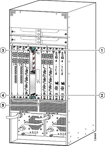
Figure 2-1 shows an example of a SIP installed in slot 6 on a Cisco 7609 router. The Cisco 7609 router has nine vertically-oriented chassis slots, which are numbered 1 to 9 from right to left.
Figure 2-1 SIP and SPA Installed in a Cisco 7609 Router
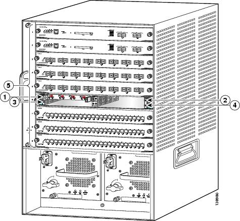
Figure 2-2 shows an example of a SIP installed in slot 6 on a Catalyst 6509 switch. The Catalyst 6509 switch has nine horizontally-oriented chassis slots, which are numbered 1 to 9 from right to left.
Figure 2-2 SIP and SPA Installed in a Catalyst 6509 Switch
SIP subslot 0
SIP subslot 3
SIP subslot 1
Chassis slots 1-9 (numbered from right to left) (numbered from top to bottom)
SIP subslot 2
Some commands allow you to display information about the SIP itself, such as show module, show sip-disk, show idprom module, show hw-module slot, and show diagbus. These commands require you to specify the chassis slot location where the SIP that you want information about is installed.
For example, to display status and information about the SIP installed in slot 6 as shown in Figure 2-1, enter the following command:
Router# show module 6For more information about SIP commands, refer to the Cisco IOS Software Releases 12.2SR Command References and to the Cisco IOS Software Releases 12.2SX Command References.
Specifying the SIP or SSC Subslot Location for a SPA
SIP subslots begin their numbering with "0" and have a horizontal or vertical orientation depending on the orientation of the SIP in the router chassis slot, as shown in the "SIP, SSC, and SPA Product Overview" chapter of the Cisco 7600 Series Router SIP, SSC, and SPA Software Configuration Guide.
Figure 2-1 shows an example of a Cisco 7600 SIP-200 installed with a vertical orientation on a Cisco 7609 router. The Cisco 7600 SIP-200 supports four subslots for the installation of SPAs. In this example, the subslot locations are vertically oriented as follows:
•
•
•
•
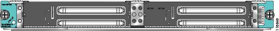
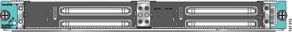
Figure 2-3 shows the faceplate for the Cisco 7600 SIP-200 in a horizontal orientation.
Figure 2-3 Cisco 7600 SIP-200 Faceplate
In this view, the subslot locations in a horizontal orientation are as follows:
•
•
•
•
The SIP subslot numbering is indicated by a small numeric label beside the subslot on the faceplate.
Just as with the SIPs, some commands allow you to display information about the SPA itself, such as show idprom module and show hw-module subslot. These commands require you to specify both the physical location of the SIP and SPA in the format, slot/subslot, where:
•
•
For example, to display the operational status for the SPA installed in the first subslot of the SIP in chassis slot 6 shown in Figure 2-1, enter the following command:
Router# show hw-module subslot 6/0 oirFor more information about SIP commands, refer to the Cisco IOS Software Releases 12.2SR Command References and to the Cisco IOS Software Releases 12.2SX Command References.
Cisco 7600 SIP-200 Overview
The following sections describe the Cisco 7600 SIP-200 (Cisco part number 7600-SIP-200):
•
•
•
Cisco 7600 SIP-200 Processor
The processor on a Cisco 7600 SIP-200 is described in Table 2-2.
Table 2-2 Cisco 7600 SIP-200 Processor
CPU
800 megahertz (MHz) internal operating frequency
Broadcom 1125 MIPS-based design
Cisco 7600 SIP-200 LEDs
The Cisco 7600 SIP-200 has one LED, as shown in Figure 2-4.
Figure 2-4 Cisco 7600 SIP-200 Faceplate
The Cisco 7600 SIP-200 LED is described in Table 2-3.
Cisco 7600 SIP-200 Physical Specifications
The Cisco 7600 SIP-200 physical specifications are shown in Table 2-4.
Cisco 7600 SIP-200 Memory Options
The following table lists the memory available for the Cisco 7600 SIP-200:
Table 2-5 SIP Memory Options
Cisco 7600 SIP-200
512 MB and 1 GB (2 x 256-MB or 2 x 512-MB DIMMs)
Note
C7600_SIP200-3-MEM_MODULE_MISMATCH: Memory modules are not identical
Cisco 7600 SIP-200 Memory Installation and Removal
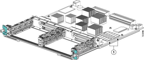
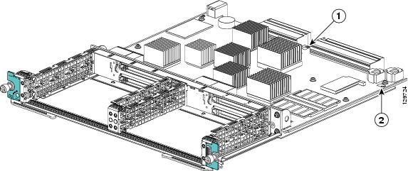
Figure 2-5 shows the location of the DIMMs on a Cisco 7600 SIP-200. Perform the following procedure to install and remove a DIMM:
To install a DIMM, slide the DIMM into the slot. The retaining clips secure the DIMM in place.
Step 1
Step 2
Figure 2-5 SIP DIMM Location
Cisco 7600 SIP-200 Default DIP Switch Settings
If SW3 and SW10 switches are present on the board, make sure they are set to the default settings, as shown in Table 2-6. See Figure 2-6 for the location of the switches.
The switches are set to their defaults during manufacture. However, the switch settings may get inadvertently changed during handling.
Note
Table 2-6 Cisco 7600 SIP-200 Default DIP Settings
Figure 2-6 Cisco 7600 SIP-200 DIP Switch Locations
\
Cisco 7600 SIP-400 Overview
The following sections describe the Cisco 7600 SIP-400 (Cisco part number 7600-SIP-400):
•
Cisco 7600 SIP-400 Processor
The processor on a Cisco 7600 SIP-400 is described in Table 2-7.
Table 2-7 7600-SIP-400 Processor
CPU
400 megahertz (MHz) internal operating frequency
Broadcom 1125 MIPS-based design
Cisco 7600 SIP-400 LEDs
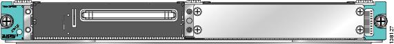
The Cisco 7600 SIP-400 has one LED, as shown in Figure 2-7.
Figure 2-7 Cisco 7600 SIP-400 Faceplate
The Cisco 7600 SIP-400 LED is described in Table 2-8.
Cisco 7600 SIP-400 Physical Specifications
The Cisco 7600 SIP-400 physical specifications are shown in Table 2-9.
Cisco 7600 SIP-600 Overview
The following sections describe the Cisco 7600 SIP-600 (Cisco part number 7600-SIP-600):
•
Cisco 7600 SIP-600 Processor
The processor on a Cisco 7600 SIP-600 is described in Table 2-10.
Table 2-10 Cisco 7600 SIP-600 Processor
CPU
400 megahertz (MHz) internal operating frequency
Broadcom 1125 MIPS-based design
Cisco 7600 SIP-600 LEDs
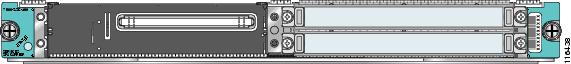
The Cisco 7600 SIP-600 has one LED, as shown in Figure 2-8.
Figure 2-8 Cisco 7600 SIP-600 Faceplate
The Cisco 7600 SIP-600 LED is described in Table 2-11.
Table 2-11 Cisco 7600 SIP-600 LED
STATUS
Red
On
The SIP has encountered an error.
Green
On
The SIP is online.
Yellow
On
The SIP is loading.
—
Off
The SIP is powered off.
Cisco 7600 SIP-600 Physical Specifications
The Cisco 7600 SIP-600 physical specifications are shown in Table 2-12.
Cisco 7600 SSC-400 Overview
The following sections describe the SPA services carrier (Cisco part number 7600-SSC-400):
•
Cisco 7600 SSC-400 Processor
The processor on a Cisco 7600 SSC-400 is described in Table 2-13.
Table 2-13 7600-SSC-400 Processor
CPU
400 megahertz (MHz) internal operating frequency
Broadcom 1125 MIPS-based design
Cisco 7600 SSC-400 LED
The Cisco 7600 SSC-400 has one LED, as shown in Figure 2-9.
Figure 2-9 Cisco 7600 SSC-400 Faceplate
The Cisco 7600 SSC-400 LED is described in Table 2-14.
Cisco 7600 SSC-400 Physical Specifications
The Cisco 7600 SSC-400 physical specifications are shown in Table 2-15.