-
Application Control Engine Module Getting Started Guide (Software Version A2(3.0))
-
Index
-
Preface
-
Overview
-
Setting Up an ACE
-
Configuring Virtualization
-
Configuring Access Control Lists
-
Configuring Role-Based Access Control
-
Configuring Server Load Balancing
-
Configuring a Load-Balancing Predictor
-
Configuring Server Persistence Using Stickiness
-
Configuring SSL Security
-
Configuring Health Monitoring Using Health Probes
-
Configuring Route Health Injection
-
Configuring Redundant ACE Modules
-
Configuring Bridged Mode
-
Configuring One-Arm Mode
-
Table Of Contents
Prerequisites for Configuring SSL
Task Flow for Configuring SSL Termination
Importing the SSL Certificate and Key Pair Files
Configuring a Traffic Policy for SSL Termination
Configuration Example for SSL Termination
Configuring SSL Security
This chapter describes how to configure Secure Sockets Layer (SSL) on the Cisco Application Control Engine (ACE) module.
This chapter contains the following sections:
•
Prerequisites for Configuring SSL
•
Information About SSL
After reading this chapter, you should have a basic understanding of how the ACE provides SSL security for your network and how to configure SSL termination, in which the ACE operates as an SSL server.
SSL configuration in an ACE establishes and maintains a SSL session between the ACE and another device. It provides for secure data transactions between a client and a server. SSL provides authentication, encryption, and data integrity in a Public Key Infrastructure (PKI), which is a set of policies and procedures that establishes a secure information exchange between devices.
In SSL, data is encrypted using one or more symmetric keys that are known only by the two endpoints in the transaction. In a key exchange, one device generates the symmetric key and then encrypts it using an asymmetric encryption scheme before transmitting the key to the other device.
Asymmetric encryption requires each device to have a unique key pair consisting of a public key and a private key. A private key is an encryption/decryption key known only to the parties exchanging the messages. A public key is a value provided by some designated authority as an encryption key that, combined with a private key derived from the public key, can be used to effectively encrypt messages and digital signatures. The two keys are mathematically related; data that is encrypted using the public key can only be decrypted using the corresponding private key, and vice versa.
SSL facilitates client and server authentication through the use of digital certificates. Digital certificates are a form of digital identification to prove the identity of the server to the client, or optionally, the client to the server. A certificate ensures that the identification information is correct and the public key embedded in it actually belongs to the client or server.
A Certificate Authority (CA) issues digital certificates in the context of a PKI. CAs are trusted authorities that sign certificates to verify their authenticity. As the certificate issuer, the CA uses its private key to sign the certificate. Upon receiving a certificate, a client uses the issuer's public key to decrypt and verify the certificate signature to ensure that the certificate was actually issued and signed by an authorized entity.
If you do not have a certificate and the corresponding key pair, you can use the ACE to generate a key pair and a certificate signing request (CSR) to apply for a certificate from a CA. The CA signs the CSR and returns the authorized digital certificate to you. The ACE supports import, export, and other management functions to manage the various certificates and key pair files within each context.
The client and server use the SSL handshake protocol to establish an SSL session between the two devices. During the handshake, the client and server negotiate the SSL parameters that they will use during the secure session. During the SSL handshake, the ACE uses an SSL proxy service, which includes the configuration of SSL session parameters, an RSA key pair, and a matching certificate.
The ACE applies SSL session parameters to an SSL proxy service. Creating an SSL parameter map allows you to apply the same SSL session parameters to different proxy services. The SSL session parameters include timeouts, close protocol behavior, and SSL version—SSL 3 and/or Transport Layer Security (TLS) 1. For more information on these parameters, see the Cisco Application Control Engine Module SSL Configuration Guide.
You can configure the ACE to act as a client or a server during an SSL session by defining operational attributes such as SSL session parameters, SSL key pairs and certificates, and traffic characteristics. When the traffic characteristics match the settings specified in the operational attributes, the ACE executes the actions associated with the SSL proxy service. Figure 9-1 shows the three basic SSL configurations in which the ACE is used to encrypt and decrypt data between the client and the server: SSL termination, SSL initiation, and end-to-end SSL.
Figure 9-1 ACE SSL Configurations
In SSL termination, an ACE context is configured for a front-end application in which the ACE operates as an SSL server that communicates with a client. When you define the flow between an ACE and a client, the ACE operates as a virtual SSL server by adding security services between a web browser (the client) and the HTTP connection (the server).
All inbound SSL flows that come from a client terminate at the ACE. After the connection is terminated, the ACE decrypts the ciphertext (encrypted content) from the client and sends the data as clear text (unencrypted content) to an HTTP server. For information about configuring the ACE for SSL termination, see the "Configuring SSL Termination" section.
In SSL initiation, an ACE context is configured for a back-end application in which the ACE operates as a client that communicates with an SSL server. When you define the flow between an ACE and an SSL server, the ACE operates as a client and initiates the SSL session. SSL initiation enables the ACE to receive clear text from a client and then establish an SSL session with an SSL server, joining the client and SSL server connections.
The ACE encrypts the clear text that it receives from the client and sends the data as ciphertext to an SSL server. The SSL server can either be an ACE configured for SSL termination (a virtual SSL server) or a real SSL server (web server). On the outbound flow from the SSL server, the ACE decrypts the ciphertext from the server and sends clear text back to the client. For more information on configuring the ACE for SSL initiation, see the Cisco Application Control Engine Module SSL Configuration Guide.
In end-to-end SSL, an ACE context is configured for both SSL termination and SSL initiation. You configure the ACE for end-to-end SSL when you have an application that requires secure SSL channels between the client and the ACE, and between the ACE and the SSL server.
For example, a transaction between banks requires end-to-end SSL to protect all financial information exchanged. End-to-end SSL also allows the ACE to insert load-balancing and security information into the data. The ACE decrypts the ciphertext that it receives and inserts load-balancing and firewall information into the clear text. The ACE then reencrypts the data and passes the ciphertext to its intended destination. For more information on configuring the ACE for end-to-end SSL initiation, see the Cisco Application Control Engine Module SSL Configuration Guide.
Prerequisites for Configuring SSL
Before configuring the ACE for an SSL operation, you must first configure it for server load balancing. To configure your ACE for server load balancing, see Chapter 6, "Configuring Server Load Balancing."
Before you configure SSL termination using the procedure in this chapter, you should have a signed SSL certificate and a key pair residing on an FTP server. For details about obtaining an SSL certificate and key pair, see the Cisco Application Control Engine Module SSL Configuration Guide.
If you do not have your own SSL certificate and key pair, for internal testing only, you can use the following Cisco-provided self-signed sample certificate and key pair files as follows:
•
•
Configuring SSL Termination
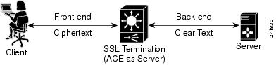
SSL termination occurs when the ACE, acting as an SSL proxy server, terminates an SSL connection from a client and then establishes a TCP connection to an HTTP server. When the ACE terminates the SSL connection, it decrypts the ciphertext from the client and transmits the data as clear text to the HTTP server.
Figure 9-2 shows the following network connections in which the ACE terminates the SSL connection with the client:
•
•
Figure 9-2 SSL Termination
SSL termination is a Layer 3 and Layer 4 application because it is based on the destination IP address of the inbound traffic flow from the client. When configuring a policy map for SSL termination, you associate the following elements:
•
•
Task Flow for Configuring SSL Termination
Follow these steps to configure SSL termination:
Step 1
Step 2
Step 3
Importing the SSL Certificate and Key Pair Files
Procedure
Creating an SSL Proxy Service
Procedure
Configuring a Traffic Policy for SSL Termination
Procedure
Configuration Example for SSL Termination
The following example shows how to configure SSL termination. The commands that you have configured in this chapter appear in bold text.
switch/VC_WEB(config)# do show running configGenerating configuration....access-list INBOUND line 8 extended permit ip any anyrserver host RS_WEB1description content server web-oneip address 10.10.50.10inservicerserver host RS_WEB2description content server web-twoip address 10.10.50.11inservicerserver host RS_WEB3description content server web-threeip address 10.10.50.12inservicerserver host RS_WEB4description content server web-fourip address 10.10.50.13inserviceserverfarm host SF_WEBpredictor hash header Acceptrserver RS_WEB1 80inservicerserver RS_WEB2 80inservicerserver RS_WEB3 80inservicerserver RS_WEB4 80inservicesticky http-cookie Cookie1 StickyGroup1timeout 3600serverfarm SF_WEBssl-proxy service PS_SSL_TERMINATIONkey cisco-sample-keycert cisco-sample-certclass-map match-all CM_SSL2 match virtual-address 10.10.40.11 tcp eq httpsclass-map type management match-any REMOTE_ACCESSdescription Remote access traffic match2 match protocol ssh any3 match protocol telnet any4 match protocol icmp anyclass-map match-all VS_WEB2 match virtual-address 10.10.40.10 tcp eq wwwpolicy-map type management first-match REMOTE_MGMT_ALLOW_POLICYclass REMOTE_ACCESSpermitpolicy-map type loadbalance first-match PM_LBclass class-defaultserverfarm SF_WEBpolicy-map multi-match PM_MULTI_MATCHclass VS_WEBloadbalance vip inserviceloadbalance policy PM_LBclass CM_SSLloadbalance vip inserviceloadbalance policy PM_LBssl-proxy server PS_SSL_TERMINATIONservice-policy input REMOTE_MGMT_ALLOW_POLICYinterface vlan 400description Client connectivity on VLAN 400ip address 10.10.40.1 255.255.255.0access-group input INBOUNDservice-policy input PM_MULTI_MATCHno shutdowninterface vlan 500description Server connectivity on VLAN 500ip address 10.10.50.1 255.255.255.0no shutdowndomain DOMAIN1add-object allip route 0.0.0.0 0.0.0.0 172.25.91.1username USER1 password 5 $1$vAN9gQDI$MmbmjQgJPj45lxbtzXPpB1 role SLB-Admin domain DOMAIN1Where to Go Next
In this chapter, you have configured an SSL proxy service and a virtual server for SSL termination. In the next chapter, you will configure server health monitoring probes (keepalives).