[an error occurred while processing this directive]

Support

Appendix B - Connector and Cable Specifications

 Feedback

Table Of Contents

Connector and Cable Specifications

Coaxial Connector and Cable Specifications

Ethernet Connector and Cabling

Power Connector

USB Connector and Cabling

Voice Port Connectors


Connector and Cable Specifications


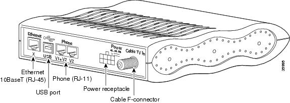
This appendix describes the pinouts and cabling requirements for the interfaces and cables used on the Cisco CVA122/CVA122E Cable Voice Adapter. All connectors for these interfaces are on the rear-panel, as shown in Figure B-1.

Figure B-1 Cisco CVA122/CVA122E Cable Voice Adapter Connectors

This appendix describes the following connectors and cabling requirements:

Coaxial Connector and Cable Specifications

Ethernet Connector and Cabling

Power Connector

USB Connector and Cabling

Voice Port Connectors

Refer to the following sections for more information.

Coaxial Connector and Cable Specifications

The Cisco CVA122/CVA122E Cable Voice Adapter connects to the HFC cable system with a type-F, right-angle, PCB-mount connector manufactured by Amp (model number 531-40047). The body is die cast out of zinc, with a tin-lead plating. The round, center contact is made of phosphor bronze, with a tin-lead plating. The insulator is polypropylene and will accept a coaxial cable center conductor with a diameter ranging from 0.022 inch (0.056 mm) to 0.042 inch (1.07 mm).

The coaxial cable used should be very high-quality cable because imperfections that do not visibly affect video transmissions can significantly affect digital data transmissions. In particular, poor insulation, improperly installed additional outlets, the condition and length of the cable's center conductor, and the quality of the cable can negatively affect the connectivity and performance of the cable voice adapter for digital data transmission.

For example, a 5 dB reduction in signal quality for analog downstream video might cause a slight degradation of picture clarity, which might or might not be noticeable to a subscriber. However, a reduction of only 1 dB in signal quality for digital data might completely disrupt service to a cable network user.

Cisco recommends that you use a headend-grade coaxial cable or a quad-shield coaxial cable with a minimum of 60% + 40% braid and double foil insulation to connect the cable modem cards to the HFC network. The center conductor must be straight and extend 1/8 inch (3.2 mm) beyond the end of the connector, and the connector should be securely crimped to the cable. The following cables are recommended:

RG-59—0.034 inch (0.86 mm) center conductor diameter

RG-59/U—0.0226 inch (0.57 mm) center conductor diameter

RG-6—0.041 inch (1.05 mm) center conductor diameter


Note All three of the coaxial cables listed can be used to connect a Cisco CVA122/CVA122E Cable Voice Adapter to the HFC network; however, the consistent use of RG-59 cable is preferred.


If you use different types of coaxial cable, the following problems can appear:

Co-channel interference—If signals at the same frequency are carried on long, parallel runs of coaxial cable, interference can occur between the signals. Higher quality cable helps to prevent this with better shielding. Co-channel interference is seen as hum or patterns in analog video channels and intermittent data loss in digital channels.

Damage to Cisco CVA122/CVA122E Cable Voice Adapter connector—The coaxial connectors are designed for RG-59 or RG-6 cable and connectors. Larger cables can damage the connectors.

High signal return loss—High quality cable and correct connectors help to ensure an optimal return loss of 16 dB or higher.

Ethernet Connector and Cabling

The Cisco CVA122/CVA122E Cable Voice Adapter has a single RJ-45 connector that provides the following Ethernet 10BaseT connectivity:

A single computer be connected directly to the cable voice adapter through the Ethernet port. Use a straight-through cable for this connection.

When the cable voice adapter is configured for routing mode, its Ethernet port can be connected to an Ethernet hub, which in turn can be connected to additional computers and other Ethernet devices. Typically, a crossover cable connects the cable voice adapter's port to the 10BaseT Ethernet port on the hub. (However, you may be able to use a straight-through cable if the hub has an uplink port; see the hub's documentation for further details.)

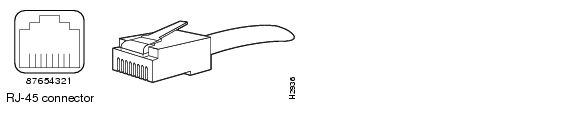
Figure B-2 shows the RJ-45 connector and plug used for the cable voice adapter's Ethernet ports. Table B-1 lists the pinouts and signals for the RJ-45 connector.

Figure B-2 RJ-45 Connector and Plug

Table B-1 RJ-45 Receptacle Pinouts

Pin
Description

1

Receive Data + (RxD+)

2

RxD-

3

Transmit Data + (TxD+)

6

TxD-


Note Referring to the RJ-45 pinout in Table B-1Table B-1, proper common-mode line terminations should be used for the unused cable pairs 4/5 and 7/8. Common-mode termination reduces electromagnetic interference (EMI).


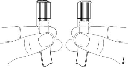
To identify the RJ-45 cable type, hold the two ends of the cable next to each other so you can see the colored wires inside the ends, as shown in Figure B-3.

Figure B-3 RJ-45 Cable Identification

Examine the sequence of colored wires to determine the type of RJ-45 cable:

Straight-through—The colored wires are in the same sequence at both ends of the cable.

Crossover—The first (far left) colored wire at one end of the cable is the third colored wire at the other end of the cable.


Note Both the standard straight-through and crossover Ethernet cables should be Category 5 UTP (RJ-45) cables. These cables are available commercially.


Power Connector

Figure B-1 shows the eight-pin power connector on the rear panel of the Cisco CVA122/CVA122E Cable Voice Adapter, and Table B-2 lists each power signal.

Figure B-4 Cisco CVA120 Series Power Connector

Table B-2 Power Connector Specifications

Pin Number
Power Signal
1

-56VDC

2

-30VDC

3

Return Ground

4

(not connected)

5

(not connected)

6

(not connected)

7

Return Ground

8

+5VDC


USB Connector and Cabling

The USB port on the Cisco CVA122/CVA122E Cable Voice Adapter uses the standard device (type "B") receptacle required by the Universal Serial Bus Specification Revision 1.1. Table B-3 lists the signals used on the USB port.

Table B-3 USB Connector Specifications

Pin Number
Signal Name
Description
1

VBUS

Power (red)

2

D-

Signal (white)

3

D+

Signal (green)

4

GND

Power Ground (black)

Shell

Shield

Shield (drain wire)


The USB connector requires a cable that meets the USB specification's requirements for a "Full-speed" detachable cable:

One end of the cable must have a host (type "A") overmolded plug and the other end of the cable must have a device (type "B") overmolded plug.

The cable cannot exceed 5 meters in length.

The signal lines (D+ and D-) must be a twisted pair (28 AWG).

Power and Signal Ground lines are non-twisted (20 to 28 AWG).

The Shield must contain a 28 AWG tinned copper drain wire.


Note See Chapter 6, "Mechanical," in the Universal Serial Bus Specification Revision 1.1 for complete connector and cable details. The specification is available at the USB Implementers Forum, Inc. web site at http://www.usb.org.


Voice Port Connectors

This section contains pinout and connection information for the two voice ports on the Cisco CVA122/CVA122E Cable Voice Adapter. The voice ports use standard voice connectors (six pins with RJ-11 connectors) and straight-through four-wire cables.


Note The service provider must enable and configure the Cisco CVA122/CVA122E Cable Voice Adapter for voice services before you can use the voice ports to make Voice over IP (VoIP) calls.


Table B-4 lists the signals used on the voice ports.

Table B-4 Voice Port Signals 

Connector
Pin
Signal
Description

V1+V2

1

NC

Not connected.

2

TIP 2

RING connection for second pair of 4-wire voice port V1+V2. This is connected in parallel with voice port V2 RING.

3

RING

RING connection for first pair of 4-wire voice port V1+V2. This is the voice port V1 RING connection.

4

TIP

TIP connection for first pair of 4-wire voice V1+V2. This is the voice port V1 TIP connection.

5

RING 2

TIP connection for second pair of 4-wire voice port V1+V2. This is connected in parallel with voice port V2 TIP.

6

NC

Not connected.

V2

7

NC

Not connected.

8

NC

Not connected.

9

RING

RING connection for voice port V2. Pin 9 on the dual connector maps to pin 3 on a standard 6-pin RJ-11.

10

TIP

TIP connection for voice port V2. Pin 9 on the dual connector maps to pin 3 on a standard 6-pin RJ-11.

11

NC

Not connected.

12

NC

Not connected.

13, 14

GND

Ground pins are connected to board ground.


[an error occurred while processing this directive]