Feedback
Table Of Contents
Configuring the OC-12 ATM Optical Services Modules
Configuring the OC-12 ATM Interfaces
Initial Configuration for the OC-12 ATM OSM
Valid VCI and VPI Configurations
Configuring the Maximum VCs per VP
Configuring Virtual Connections
Configuring Bridging of RFC 1483 Routed Encapsulations
Configuring PVC Traffic Parameters
Configuring Communication with the ILMI
Configuring the PVC that Performs SVC Call Setup
Configuring Multipoint Bridging
Restrictions and Usage Guidelines
Configuring Multipoint Bridging for ATM Interfaces
RFC 1483 Spanning-Tree Interoperability Enhancements
Supported Supervisors and Line Cards
The Interoperability Problem Summarized
BPDU Translation Command Line Interface Summary
Typical Topologies Requiring BPDU Translation
Configuring Automatic Protection Switching
Configuring the Working Interface
Configuring the Protect Interface
Configuring Basic APS on a Single Router
Basic Multiple Router APS Configuration
Multiple APS Interface Configuration
SONET and SDH Configuration Commands
Configuring the OC-12 ATM Optical Services Modules
This chapter describes the 2-port OC-12 ATM WAN Optical Services Modules (OSMs).
This chapter consists of these sections:
•
Configuring the OC-12 ATM Interfaces
•
•
•
ATM Overview
Asynchronous Transfer Mode (ATM) uses cell-switching and multiplexing technology that combines the benefits of circuit switching (constant transmission delay and guaranteed capacity) with the benefits of packet switching (flexibility and efficiency for intermittent traffic).
ATM is a connection-oriented environment. All traffic to or from an ATM network is prefaced with a virtual path identifier (VPI) and virtual channel identifier (VCI). A VPI/VCI pair is considered a single virtual circuit. Each virtual circuit is a private connection to another node on the ATM network. Each virtual circuit is treated as a point-to-point mechanism to another router or host and can support bidirectional traffic.
Each ATM node is required to establish a separate connection to every other node in the ATM network that it must communicate with. All such connections are established using a permanent virtual circuit (PVC), which a network operator configures, or a switched virtual circuit (SVC), which is set up and torn down with an ATM signaling mechanism. This signaling is based on the ATM Forum User-Network Interface (UNI) specification V3.x, 4.0.
Supported Features
The WAN ports on the 2-port OC-12 ATM OSMs support the following features:
•
•
•
•
•
•
•
•
•
•
•
•
•
•
•
–
–
•
•
•
•
•
•
•
•
•
•
•
Note
For QoS configuration information and examples for the WAN OSM ports, see the "Configuring QoS on the OSMs" section on page 9-2.
For MPLS QoS configuration information and examples for the WAN OSM ports, see the "Configuring MPLS QoS" section on page 11-13.
For general information on how to configure Cisco IOS QoS, refer to these Cisco IOS publications:
Cisco IOS Quality of Service Solutions Configuration Guide at this URL:
http://www.cisco.com/univercd/cc/td/doc/product/software/ios121/121cgcr/qos_c/index.htm
Cisco IOS Quality of Service Solutions Command Reference at this URL:
http://www.cisco.com/univercd/cc/td/doc/product/software/ios121/121cgcr/qos_r/index.htm
Configuring the OC-12 ATM Interfaces
This section provides procedures for initial configuration of an OC-12 ATM OSM interface:
•
•
Initial Configuration for the OC-12 ATM OSM
On power-on, the interfaces on a new OC-12 ATM OSM are shut down. To enable an interface, you must enter the no shutdown command in configuration mode. When the OC-12 ATM interface is enabled with no additional configuration, the default interface configuration file parameters are used. These default parameters are listed in Table 8-1.
After you verify that the new OC-12 ATM module is installed correctly (the active LED goes on and all cables are correctly connected), you can use the configure command to configure the ATM interfaces.
Enabling the ATM Interface
A Cisco Catalyst 6000 family switch and Cisco 7600 series router identifies an interface address by its slot number and port number in the format slot/port. For example, the slot/port address of an interface on a 2-port OC-12 ATM OSM installed in slot 4 is 4/1.
Before using the configure command, you must enter the privileged level mode of the EXEC command interpreter by using the enable command. The system prompts you for a password if one is set.
Use the following procedure to configure the 2-port OC-12 ATM OSMs. Press the Return key after each configuration step unless otherwise noted.
To configure the ATM interfaces, perform this task:
This example shows how to configure an OC-12 ATM OSM interface:
Router# configure terminalRouter(config)# interface atm 4/0Router(config-if)# ip address 1.2.3.4 255.255.255.0Router(config-if)# no shutdownRouter# copy running-config startup-configValid VCI and VPI Configurations
The default number of VPIs per ATM interface is 15. The maximum number of VCIs per VPI is 1023.
Table 8-2 shows the valid VCs per VP and maximum VPI configurations.
Table 8-2 Valid VCI and VPI Configurations
1024
15
512
31
256
63
128
127
64
255
32
255
16
255
Configuring the Maximum VCs per VP
The ATM interfaces are configured by default to allow a maximum of 1023 VCs per VP. To change this value, perform this task beginning in global configuration mode:
Configuring Virtual Connections
This section provides basic information for configuring PVCs, bridged PVCs (RFC 1483), PVC traffic parameters, and SVCs. In addition, this section documents commands and configurations that are unique to the 2-port OC-12 ATM OSMs.
•
•
•
•
For all other Cisco IOS features and commands supported on the OC-12 ATM OSMs, refer to the "Configuring ATM" chapter in the Cisco IOS Wide-Area Networking Configuration Guide, Release 12.1 at this URL:
http://www.cisco.com/univercd/cc/td/doc/product/software/ios121/121cgcr/wan_c/wcdatm.htm
For complete command syntax information, refer to the "ATM commands" chapter in the Cisco IOS Wide-Area Networking Command Reference, Release 12.1 at this URL:
http://www.cisco.com/univercd/cc/td/doc/product/software/ios121/121cgcr/wan_r/wratm/index.htm
Creating a PVC
To create a PVC on the ATM interface and enter interface-ATM-VC configuration mode, perform this task in interface configuration mode:
This example shows how to create a PVC:
Router(config)# interface atm 4/0Router(config-if)# ip address 10.212.13.4 255.255.255.0Router(config-if)# no shutdownRouter(config-if)# pvc cisco 0/56Router(config-if-atm-vc)# protocol ip 10.212.13.5 broadcastRouter(config-if-atm-vc)# encapsulation aal5snapRouter(config-if-atm-vc)#Configuring Bridging of RFC 1483 Routed Encapsulations
Bridging of routed encapsulations (BRE) enables the OC-12 ATM OSM to receive RFC 1483 routed encapsulated packets and forward them as Layer 2 frames.
Note
When you configure BRE on an ATM PVC on the OC-12 ATM OSM:
1.
2.
3.
4.
Figure 8-1 shows a topology in which an OC-12 ATM OSM receives routed PDUs, encapsulates them as Layer 2 frames, and forwards these frames to a Layer 2 customer device.
Figure 8-1 Example BRE Topology
To configure BRE on a PVC, use the following commands:
Step 1
Router# configure terminalRouter(config)# vlan 10Router(config-vlan)# exitStep 2
Router(config)# interface vlan 10Router(config-if)# no shutdownRouter(config-if)# endRouter#Step 3
Router(config)# interface GigabitEthernet3/3Router(config-if)# no ip addressRouter(config-if)# switchportRouter(config-if)# switchport access vlan 10Router(config-if)# switchport mode accessRouter(config-if)# endRouter#Step 4
Router(config)# interface atm3/1Router(config-if)# no ip addressRouter(config-if)# no shutdownRouter(config-if)# endRouter#
Step 5
Router(config)# interface atm3/1.1 point-to-point
Router(config-if)# no ip address
Router(config-subif)# mtu 1500
Router(config-subif)# pvc 1/101
Router(config-if-atm-vc)# bre-connect 10
Router(config-subif)# end
Router#
Note
Configuring PVC Traffic Parameters
The supported traffic parameters are part of the following service categories: Unspecified Bit Rate (UBR) and Variable Bit Rate Non Real-Time (VBR-NRT). Only one of these categories can be specified per PVC connection; if a new one is entered, it replaces the existing one.
To configure PVC traffic parameters, perform one of these tasks beginning in interface-ATM-VC configuration mode:
Router(config-if-atm-vc)# ubrConfigures UBR. The default is UBR.
Configures VBR-NRT.
The -pcr, -scr, and -mbs arguments are the peak cell rate, sustainable cell rate, and maximum burst size.
The maximum configurable speed of a VBR-NRT PVC is 299520 Mbps. The maximum MBS is 255 cells.
This example shows how to configure VBR-NRT with a peak cell rate of 1000, a sustainable cell rate of 500, and a maximum burst size of 64:
Router(config-if-atm-vc)# vbr-nrt 1000 500 64Router(config-if-atm-vc)#Configuring SVCs
ATM SVCs are created and released dynamically, providing user bandwidth on demand. This service requires a signaling protocol between the router and the switch.
The ATM signaling software provides a method of dynamically establishing, maintaining, and clearing ATM connections at the UNI. The ATM signaling software conforms to ATM Forum UNI 3.x, 4.0 depending on the version selected by the ILMI or the configuration.
In UNI mode, the Cisco 7600 series router does not perform ATM-level call routing. Instead, the ATM switch performs the ATM call routing, and the router routes packets through the resulting circuit. The router is viewed as the user and the LAN interconnection device at the end of the circuit, and the ATM switch is viewed as the network.
You must complete the tasks in the following sections to use SVCs:
•
•
•
•
Configuring Communication with the ILMI
In an SVC environment, you must configure a PVC for communication with the Integrated Local Management Interface (ILMI) so the router can receive SNMP traps and new network prefixes. The recommended vpi and vci values for the ILMI PVC are 0 and 16, respectively. To configure ILMI communication, perform the following task in interface configuration mode:
Router(config-if)# pvc [name] vpi/vci [ilmi | qsaal]
Creates an ILMI PVC on an ATM main interface.
This example shows how to create an ILMI PVC on an ATM main interface:
Router(config-if)# pvc cisco 0/16 ilmi
Note
After you configure an ILMI PVC, you can optionally enable the ILMI keepalive function by performing the following task in interface configuration mode:
Router(config-if)# atm ilmi-keepalive [seconds]
Enables ILMI keepalives and sets the interval between keepalives.
ILMI address registration for receipt of SNMP traps and new network prefixes is enabled by default. The ILMI keepalive function is disabled by default; when enabled, the default interval between keepalives is 3 seconds.
This example shows how to set the ILMI keepalive interval to 3 minutes:
Router(config-if)# atm ilmi-keepalive 180Configuring the PVC that Performs SVC Call Setup
One dedicated PVC exists between the router and the ATM switch, over which all SVC call-establishment and call-termination requests flow. After the call is established, data transfer occurs over the SVC, from router to router.
Before any SVCs can be set up, a signaling PVC must be configured.
To configure the signaling PVC for all SVC connections, perform this task in interface configuration mode:
Router(config-if)# pvc [name] vpi/vci [ilmi | qsaal]
Configures the signaling PVC for an ATM main interface that uses SVCs.
This example shows how to configure the signaling PVC:
Router(config-if)# pvc 0/5 qsaalRouter(config-if-atm-vc)#
Note
The VPI and VCI values must be configured consistently with the ATM switch. The standard value for VPI is 0 and VCI is 5.
Configuring the NSAP Address
Each ATM interface involved with signaling must be configured with a network service access point (NSAP) address. The NSAP address is the ATM address of the interface and must be unique across the network.
To configure an NSAP address, complete the tasks described in one of the following sections:
•
•
Configuring the ESI and Selector Fields
If the switch is capable of delivering the NSAP address prefix to the router by using ILMI, and the router is configured with a PVC for communication with the switch through ILMI, you can configure the end station ID (ESI) and selector fields using the atm esi-address command. The atm esi-address command allows you to configure the ATM address by entering the ESI (12 hexadecimal characters) and the selector byte (2 hexadecimal characters). The NSAP prefix (26 hexadecimal characters) is provided by the ATM switch.
To configure the router to get the NSAP prefix from the switch and use locally entered values for the remaining fields of the address, perform this task in Interface configuration mode:
Router(config-if)# pvc 0/16 ilmiRouter(config-if-atm-vc)# exitRouter(config-if)# atm esi-address 3456.7890.1234.12The recommended vpi value for the ILMI PVC is 0 and the recommended vci value is 16.
You can also specify a keepalive interval for the ILMI PVC.
Configuring the Complete NSAP Address
When you configure the ATM NSAP address manually, you must enter the entire address in hexadecimal format because each digit entered represents a hexadecimal digit. To represent the complete NSAP address, you must enter 40 hexadecimal digits in the following format:
XX.XXXX.XX.XXXXXX.XXXX.XXXX.XXXX.XXXX.XXXX.XXXX.XX
Note
Because the interface has no default NSAP address, you must configure the NSAP address for SVCs. To set the ATM interface source NSAP address, perform this task in interface configuration mode:
Router(config-if)# atm nsap-address nsap-address
Configures the ATM NSAP address for an interface.
This example shows how to configure the NSAP address:
Router(config-if)# atm nsap-address BC.CDEF.01.234567.890A.BCDE.F012.3456.7890.1334.13Router(config-if)#The atm nsap-address and atm esi-address commands are mutually exclusive. Configuring the router with the atm nsap-address command negates the atm esi-address setting and vice versa. You can display the ATM address for the interface by executing the show interface atm command.
Creating an SVC
To create an SVC, perform this task in interface configuration mode:
After you specify a name for an SVC, you can reenter interface-ATM-VC configuration mode by entering the svc name command; you can remove an SVC configuration by entering the no svc name command.
For a list of AAL types and encapsulations supported for the aal-encap argument, refer to the encapsulation aal5 command in the "ATM Commands" chapter of the Cisco IOS Wide-Area Networking Command Reference. The default is AAL5 with SNAP encapsulation.
This example shows how to create an SVC:
Router(config-if)# svc nsap BC.CDEF.01.234567.890A.BCDE.F012.3456.7890.1334.13Router(config-if-atm-vc)# encapsulation aal5muxRouter(config-if-atm-vc)# protocol ip 1.1.1.5 broadcastRouter(config-if-atm-vc)#Configuring Multipoint Bridging
Multipoint bridging enables point-to-multipoint bridging for ATM permanent virtual circuits (PVCs). This feature allows the use of multiple VCs per VLAN for bridging.
Multipoint bridging allows service providers to add support for Ethernet-based Layer 2 services to the proven technology of their existing ATM legacy networks. Customers can then use their current VLAN-based networks over the ATM cloud. This also allows service providers to gradually update their core networks to the latest Gigabit Ethernet optical technologies, while still supporting their existing customer base.
ATM interfaces use RFC 1483 bridging which provides an encapsulation method to allow the transport of Ethernet frames over each type of Layer 2 network.
Note
In Cisco IOS Release 12.2(18)SXE, multipoint bridging supports the following modes of operation:
•
•
•
•
Restrictions and Usage Guidelines
The following restrictions apply to the Multipoint Bridging feature:
•
•
•
•
•
•
Prerequisites
The following prerequisites apply to multipoint bridging:
•
•
Configuring Multipoint Bridging for ATM Interfaces
This section describes how to configure multipoint bridging on ATM interfaces. You can configure multipoint bridging manually on individual PVCs, or you can configure a range of PVCs to configure all of the PVCs at one time. To perform either task or both, use the following procedure.
SUMMARY STEPS
1.
2.
3.
4.
5.
Note
6.
Note
7.
8.
Note
9.
Note
10.
11.
DETAILED STEPS
Step 1
enable
Example:Router> enable
Enables privileged EXEC mode. Enter your password if prompted.
Step 2
configure terminal
Example:Router# configure terminal
Enters global configuration mode.
Step 3
vlan {vlan-id | vlan-range}
Example:Router(config)# vlan 2,5,10-12,20,25,4000
Adds the specified VLAN IDs to the VLAN database and enters VLAN configuration mode.
•
•
Note
Step 4
interface atm slot/port
Example:Router(config)# interface atm 8/0
Enters configuration mode for the specified ATM interface.
Step 5
no ip address
Example:Router(config-if)# no ip address
Removes the IP address on the main interface.
Step 6
interface atm slot/port.subinterface [point-to-point | multipoint]
Example:Router(config-if)# interface atm 8/0.100
(Optional) Enters configuration mode for the specified subinterface, assuming that you are using subinterfaces to organize the PVCs.
•
•
Use the following two commands (pvc and bridge-domain) to create and configure PVCs individually. Repeat these commands as desired.
Step 7
pvc [name] vpi/vci
Example:Router(config-if)#
Configures a new ATM PVC with the specified VPI and VCI numbers:
•
•
Step 8
bridge-domain vlan-id [access | dot1q | dot1q-tunnel] [ignore-bpdu-pid] [split-horizon]
Example:Router(config-if-atm-vc)#
Enables RFC 1483 bridging to map a bridged VLAN to a PVC. The following options are supported:
Note
•
Note
•
•
•
Note
•
•
Note
Note
Note
Step 9
range [range-name] pvc [start-vpi/]start-vci [end-vpi/]end-vci
Example:Router(config-if-atm-vc)# range pvc 1/121 1/180
Creates a range of PVCs, and enters PVC range configuration mode:
•
•
•
•
•
Step 10
bridge-domain vlan-id [access | dot1q | dot1q-tunnel] [ignore-bpdu-pid] [increment] [split-horizon]
Example:Router(config-if-atm-range)# bridge-domain 121 increment
Router(config-if-atm-range)#
Enables RFC 1483 bridging to map a bridged VLAN to the configured range of PVCs. In addition to the options that are shown in Step 8, this command supports the following option when used in PVC range configuration mode:
•
Step 11
end
Example:Router(config-if-atm-range)# end
Router#
Exits VC or PVC range configuration mode and returns to privileged EXEC mode.
The following example shows both a range of PVCs and an individual PVC being configured for multipoint bridging:
interface ATM3/1.101 multipointrange pvc 102/100 102/102bridge-domain 102 increment!mls qos trust dscpVerification
To display information about the PVCs that have been configured on ATM interfaces, use the following commands:
•
•
Tip
The following shows an example of each command:
Router# show atm pvcVCD / Peak Avg/Min BurstInterface Name VPI VCI Type Encaps SC Kbps Kbps Cells Sts3/1.100 3 101 100 PVC SNAP UBR 599040 UP3/1.100 4 111 100 PVC SNAP UBR 599040 UP3/2.100 3 102 100 PVC SNAP UBR 599040 UP3/2.100 4 112 100 PVC SNAP UBR 599040 UPRouter# show atm vlanOptions Legend: DQ - dot1q; DT - dot1q-tunnel; MD - multi-dot1q;AC - access; SP - split-horizon; BR - broadcast;IB - ignore-bpdu-pid;DEF - defaultInterface VCD VPI Network Customer PVC Options/VCI Vlan ID Dot1Q-ID StatusATM3/1.100 3 101/100 101 - UP DEFATM3/1.100 4 111/100 111 - UP DEFATM3/2.100 3 102/100 102 - UP DEFATM3/2.100 4 112/100 112 - UP DEFRFC 1483 Spanning-Tree Interoperability Enhancements
The RFC 1483 Spanning-Tree Interoperability Enhancements feature allows interoperability between two different BPDU formats (PVST+ and 802.1d) between Cisco 7600 series routers and legacy Catalyst 5500 ATM switches, Cisco 7200 routers, and Cisco 7500 routers.
This section describes an interoperability feature for the various Spanning-Tree implementations across 1483 Bridge-Mode ATM PVCs. Historically, vendors have not implemented Spanning-Tree across 1483 encapsulation consistently; furthermore, some Cisco IOS versions may not support the full range of Spanning-Tree options. This feature attempts to smooth some of the practical challenges of interworking common variations of Spanning-tree over RFC 1483 Bridged-Mode encapsulation.
Note
Let's first define the basic terms:
•
•
•
•
•
Note
Supported Supervisors and Line Cards
The Cisco 7600 router supports PVST to PVST+ BPDU interoperability with the following Supervisors and line cards:
Supervisor 720 Line Cards
•
•
•
•
Supervisor 2 Line Cards
•
•
•
Prerequisites
The RFC 1483 Spanning-Tree Interoperability Enhancements feature requires Cisco IOS Release 12.2(18)SXF1 or later.
The Interoperability Problem Summarized
The current interoperability problem can be summarized as follows:
•
•
When the Cisco 7600 router and the Catalyst 6500 switch first implemented 1483 Bridging (on Cisco IOS 12.1E) on the Cisco 7600 FlexWAN module, the platform uses OUI: 00-80-C2 and PID: 00-0E to maximize interoperability with all other Cisco IOS products.
However, there are so many implementations that do not send PVST or 802.1D BPDUs with PID: 00-0E that the Cisco 7600 and the Catalyst 6500 reverted to the more common implementation of RFC 1483 (with PID: 00-07) in Cisco IOS 12.2SX. This feature provides the option of encapsulating BPDUs across 1483 with either PID: 00-07 or PID: 00-0E.
BPDU Packet Formats
In this section, the various BPDU packet formats are described. Figure 8-2 shows the generic IEEE 802.2/802.3 frame format, which is used by PVST+—but is not used by PVST.
Figure 8-2 IEEE 802.2/802.3 SNAP Encapsulation (RFC 1042)
Catalyst 5000 PVST BPDU Packet Format
The Catalyst 5000 Series switches send and receive BPDUs in PVST format on ATM interfaces (see Figure 8-3):
Figure 8-3 BPDU PVST Frame Used by the Catalyst 5000 Switch
BPDUs sent by the Catalyst 5000 use a PID of 0x00-07, which does not comply with RFC1483. The Cisco 7600 router also has the ability to send BPDUs in this data format.
By using the bridge-domain command's ignore-bpdu-pid optional keyword, the Catalyst 5000 switch sends this frame by default.
The Catalyst 5000 cannot accept the PVST+ BPDUs and blocks the ATM port, giving the following error message:
%SPANTREE-2-RX_1QNON1QTRUNK: Rcved 1Q-BPDU on non-1Q-trun port 6/1 vlan 10
%SPANTREE-2-RX_BLKPORTPVID: Block 6/1 on rcving vlan 10 for inc peer vlan 0
Cisco 7200/7500 IEEE BPDU Frame Format
Figure 8-4 shows the Cisco 7200/7500 routers IEEE BPDU frame format:
Figure 8-4 Frame Format for the Cisco 7200/7500 IEEE BPDU
Cisco 7600 PVST+ BPDU Frame Format
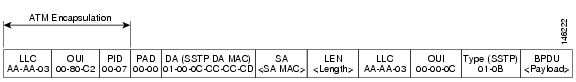
The Cisco 7600 router PVST+ BPDU packet format is as shown in Figure 8-5. These BPDUs are not IEEE BPDUs, but Cisco proprietary SSTP BPDUs.
Figure 8-5 Cisco 7600 PVST+ BPDU Frame (1483 Bridged)
Cisco L2PT BPDU Frame Format
Figure 8-6 shows the Cisco Layer 2 Protocol Tunneling (L2PT) BPDU SNAP frame format:
Figure 8-6 L2PT BPDU SNAP Frame Format
BPDU Translation Command Line Interface Summary
In order to resolve the interoperability problem as described in the previous section, Cisco has introduced the following new keywords for the bridge-domain command:
•
•
The ignore-bpdu-pid Keyword
Without the ignore-bpdu-pid keyword, the permanent virtual circuit (PVC) between the devices operates in an RFC 1483 compliant manner, which is referred to as strict mode. Using the ignore-bpdu-pid keyword is known as loose mode.
•
•
For details, refer to the "BPDU Packet Formats" section.
Cisco proprietary PVST+ BPDUs are always sent out on data frames using a PID of 0x00-07, regardless of whether the ignore-bpdu-pid keyword is used.
Use the <ignore> keyword when connecting to devices that send PVST (or 802.1D) BPDUs with PID: 00-07. This includes the vast majority of CPE devices, such as ATM DSL modems.
The pvst-tlv Keyword
The pvst-tlv keyword enables BPDU translation when interoperating with devices that understand only PVST or IEEE Spanning Tree Protocol. Since the Cisco 7600 ATM modules support PVST+ only, the pvst-tlv keyword must be used when connecting to a Catalyst 5000 switch, which only understands PVST on its ATM modules, or when connecting with other Cisco IOS routers, which understand IEEE format only.
•
•
When a Cisco 7600 Router Is Connected to a Cisco 7200 Router
For example, the Cisco 7200 router is a device that only understand IEEE BPDUs in an RFC 1483 compliant manner. Thus, when a Cisco 7600 router is connected to a Cisco 7200 router, the keywords used should be as follows:
bridge-domain <vlan> pvst-tlv <vlan>
The ignore-bpdu-pid keyword is not used in this case because the Cisco 7200 router must operate in an RFC 1483 compliant manner for IEEE BPDUs.
When a Cisco 7600 Router Is Connected to a Catalyst 5500 ATM Module
The Catalyst 5500 ATM module is a device that only understands PVST BPDUs in a non-RFC1483 compliant manner. Therefore, when a Cisco 7600 router is connected to a Catalyst 5500 ATM module, we need to use both keywords:
bridge-domain <vlan> ignore-bpdu-pid pvst-tlv <vlan>
Layer 2 Protocol Tunneling Topology CLI
To enable BPDU translation for the Layer 2 Protocol Tunneling (L2PT) topologies, use the following command line:
bridge-domain <PE vlan> dot1q-tunnel ignore-bpdu-pid pvst-tlv <CE vlan>
Typical Topologies Requiring BPDU Translation
This section describes the most common network scenarios and provides the configuration commands necessary to enable BPDU translation between the devices in each example.
Layer 2 Protocol Tunneling Topology with a Cisco 7600, Catalyst 5500, and Catalyst 6500
Figure 8-7 shows one sample network topology in which data packets are sent between a Catalyst 5500 switch and a Cisco 7600 router:
Figure 8-7 Catalyst 5500 Switch and Cisco 7600 Routers in an L2PT Topology
As shown in Figure 8-7, Layer 2 Protocol Tunneling (L2PT) is configured at the Cisco 7600 ATM6/1/0 interface and also at the Catalyst 6500 Ethernet2/1 interface.
PVST packets are sent from the Catalyst 5500 switch to the Cisco 7600 router. The Cisco 7600 router transports those BPDUs via L2PT and sends them to the Catalyst 6500. Those BPDUs are decapsulated and restored before sending the packets out to the customer network.
Assume that the 7600 and the Catalyst 6500 are PE devices and the rest are CE devices.
ATM Configuration Example
Any traffic coming in must be sent via a dot1q-tunnel. Assuming the PE-VLAN is 200 and the CE-VLAN is 100, we have the following configuration:
Router(config)#int atm 6/1/0
Router(config-if)#pvc 6/200
Router(config-if-atm-vc)#bridge-domain 200 dot1q-tunnel ignore-bpdu-pid pvst-tlv 100
Router(config-if-atm-vc)#
Ethernet Configuration Example
The Ethernet configuration is something like this:
Router(config)#int gig2/1/0
Router(config-if)#switchport
Router(config-if)#switchport access vlan 200
Router(config-if)#switchport mode dot1q-tunnel
Router(config-if)#l2protocol-tunnel
CE-VLAN 100 is what is used at the customer sites. The Catalyst 5500 sends the IEEE BPDU in data format. The Cisco 7600 router receives the BPDU and first converts it to PVST+ format. Then the DA MAC of the frame is changed to the protocol tunnel MAC address and sent out into the Layer 2 cloud.
At the other end, when the frame leaves the gige2/1/0 interface, the DA MAC is changed back to the PVST+ DA MAC and the PVST+ BPDU is sent to the CPE device.
Layer 2 Protocol Tunneling Topology with a Cisco 7600 and Cisco 7200
In the example shown in Figure 8-8, a Cisco 7600 router needs to communicate with a Cisco 7200 router:
Figure 8-8 Cisco 7600 and Cisco 7200 Routers in an L2PT Topology
PE Configuration
On the PEs, the configuration looks something like this:
!On PE 1interface ATM2/0/0no ip addressatm mtu-reject-callpvc 7/101bridge-domain 200 dot1q-tunnel!end!On PE 2interface ATM3/0/0no ip addresspvc 2/101bridge-domain 200 dot1q-tunnel pvst-tlv 100!endCisco 7600 CE Configuration
The configuration for the Cisco 7600 CE 1 would be as follows:
!On CE 1interface ATM1/1/0no ip addressatm mtu-reject-callpvc 7/101bridge-domain 101!endCisco 7200 CE Configuration
The configuration for the Cisco 7200 (CE 2) router would be like this:
!On CE 2interface ATM4/0no ip addressno atm ilmi-keepalivepvc 2/101!bridge-group 101endData Transmission Sequence from the Cisco 7200 CE to the Cisco 7600 CE
Given the configurations and topologies summarized here, the data transmission sequence from the Cisco 7200 CE to the Cisco 7600 CE is as follows:
1.
2.
3.
4.
5.
6.
7600 Basic Back-to-Back Scenario
The basic back-to-back scenario in Figure 8-9 is as follows:
Figure 8-9 Cisco 7600 Routers in Basic Back-to-Back Topology
The PDUs exchanged are PVST+ BPDUs. The PVST+ BPDUs are sent using a PID of 0x0007. Here is the configuration:
Router(config)#int atm 2/1/0
Router(config-if)#pvc 2/202
Router(config-if-atm-vc)#bridge-domain 101
Router(config-if-atm-vc)#
Catalyst 5500 Switch and Cisco 7600 Routers in Back-to-Back Topology
Another sample topology, shown in Figure 8-10, is a simple back-to-back setup, which serves to test basic Catalyst 5500 and Cisco 7600 interoperability.
Figure 8-10 Catalyst 5500 Switch and Cisco 7600 Routers in Back-to-Back Topology
When connected to a device that sends and receives IEEE BPDUs in data format (PID 0x0007) like the Catalyst 5000's ATM module, the configuration must be something like this:
Router(config)#int atm 2/1/0
Router(config-if)#pvc 2/202
Router(config-if-atm-vc)#bridge-domain 101 ignore-bpdu-pid pvst-tlv 101
Router(config-if-atm-vc)#
The Cisco 7600 router translates its outgoing PVST+ BPDUs into IEEE BPDUs. Because the ignore-bpdu-pid keyword is also enabled, it uses a PID of 0x0007, which is exactly what the Catalyst 5500 switch expects.
Cisco 7600 and Cisco 7200 in Back-to-Back Topology
When connecting to a device that is completely RFC1483 compliant, in which the IEEE BPDUs are sent using a PID of 0x000E, you must use the new ignore-bpdu-pid keyword in the bridge-domain command.
Figure 8-11 Cisco 7600 Router and Cisco 7200 Router in Back-to-Back Topology
For example, when a Cisco 7600 is connected to a Cisco 7200 router, you would have this configuration:
Router(config)#int atm 2/1/0
Router(config-if)#pvc 2/202
Router(config-if-atm-vc)#bridge-domain 101 pvst-tlv 101
Router(config-if-atm-vc)#
Note
Configuring Automatic Protection Switching
The Automatic Protection Switching (APS) feature supports Linear 1+1 APS as described in section 5.3 of the Telcordia publication"GR-253-CORE SONET Transport Systems: Common Generic Criteria."
Linear APS is defined to provide protection at the line layer. All of the STS synchronous payload envelopes (SPEs) carried in an OC-N signal are protected so that if a protection switch occurs, all of the VCs are switched simultaneously.
One port on an OC-12 ATM OSM can be protected by:
•
•
•
Note
When configuring APS, we recommend that you configure the working interface first, along with the IP address of the interface being used as the APS OOB communication path.
Note
For more information on APS and configuration information for additional APS features, refer to the Cisco IOS Interface Configuration Guide, Release 12.1 at this URL:
http://www.cisco.com/univercd/cc/td/doc/product/software/ios121/121cgcr/inter_c/index.htm
Configuring the Working Interface
To configure the working interface, perform this task:
Note
Note
Configuring the Protect Interface
To configure the protect interface, perform this task beginning in global configuration mode:
Configuring Basic APS on a Single Router
Figure 8-12 shows the configuration of APS on router A and router B. Router A has both the working and protect interfaces. If the working interface ATM1/0 becomes unavailable, the connection automatically switches over to the protect interface ATM3/0. Single router APS configuration is typically used to protect line card failures.
Figure 8-12 Basic Single Router APS Configuration
Step 1
RouterA# configure terminalRouterA(config)# interface Loopback 0/0RouterA(config-if)# ip address 7.7.7.7 255.255.255.255RouterA(config-if)# endRouterA#Step 2
RouterA# configure terminalRouterA(config)# interface ATM 1/0RouterA(config-if)# aps working 1RouterA(config-if)# exitRouterA(config)# interface ATM 3/0RouterA(config-if)# aps protect 1 7.7.7.7RouterA(config-if)# endStep 3
RouterA# configure terminalRouterA(config)# int atm 1/0.1 point-to-pointRouterA(config-subif)# ip address 10.1.1.1 255.255.255.0RouterA(config-subif)# pvc 0/100RouterA(config-subif)# exitRouterA(config)# int atm 3/0.1 point-to-pointRouterA(config-subif)# ip address 10.1.1.1 255.255.255.0RouterA(config-subif)# pvc 0/100RouterA(config-subif)# exitRouterA(config)# endRouterA#
Note
Basic Multiple Router APS Configuration
Figure 8-13 shows the configuration of APS on router A and router B. Router A is configured with the working interface and router B is configured with the protect interface. If the working interface on router A becomes unavailable, the connection automatically switches over to the protect interface on router B. This is typically used to protect against both line card and router failures.
Figure 8-13 Basic Multiple Router APS Configuration
Step 1
RouterA# configure terminalRouterA(config)# interface ethernet 0/0RouterA(config-if)# ip address 7.7.7.7 255.255.255.0RouterA(config-if)# exitRouterA(config)# interface ATM 1/0RouterA(config-if)# aps working 1RouterA(config-if)# endRouterA#Step 2
RouterB# configure terminalRouterB(config)# interface ethernet 0/0RouterB(config-if)# ip address 7.7.7.6 255.255.255.0RouterB(config)# interface ATM 3/0RouterB(config-if)# aps protect 1 7.7.7.7RouterB(config-if)# endRouterB#Step 3
RouterA# configure terminalRouterA(config)# int atm 1/0.1 point-to-pointRouterA(config-subif)# ip address 10.1.1.1 255.255.255.0RouterA(config-subif)# pvc 0/100RouterA(config-subif)# exitRouterA(config)# endRouterA#Step 4
RouterB# configure terminalRouterB(config)# int atm 3/0.1 point-to-pointRouterB(config-subif)# ip address 10.1.1.1 255.255.255.0RouterB(config-subif)# pvc 0/100RouterB(config-subif)# exitRouterB(config)# endRouterB#Multiple APS Interface Configuration
To configure more than one protect/working interface on a router, use the aps group command. Figure 8-14 shows the configuration for grouping more than one working/protect interface on a router. Both router A and B are configured with a working interface and a protect interface. If the working interface 2/0 on router A becomes unavailable, the connection switches over to the protect interface 3/0 on router B because they are both in APS group 10. Similarly, if the working interface 2/0 on router B becomes unavailable, the connection switches over to the protect interface 3/0 on router A because they are both in APS group 20.
Figure 8-14 Multiple APS Interface Configuration
Note
Step 1
RouterA# configure terminalRouterA(config)# interface ethernet 0/0RouterA(config-if)# ip address 7.7.7.6 255.255.255.0RouterA(config)# interface ATM2/0RouterA(config)# aps group 10RouterA(config-if)# aps working 1RouterA(config)# interface ATM3/0RouterA(config-if)# aps group 20RouterA(config-if)# aps protect 1 7.7.7.7RouterA(config-if)# endRouterA#Step 2
RouterB# configure terminalRouterB(config)# interface ethernet 0/0RouterB(config-if)# ip address 7.7.7.7 255.255.255.0RouterB(config)# interface ATM2/0RouterB(config)# aps group 20RouterB(config-if)# aps working 1RouterB(config)# interface ATM3/0RouterB(config-if)# aps group 10RouterB(config-if)# aps protect 1 7.7.7.6RouterB(config-if)# endRouterB#
APS Commands
The commands below are applicable to APS with ATM. For information on using these commands, see http://www.cisco.com/univercd/cc/td/doc/product/software/ios111/cc111/posaps.htm#xtocid13.
Note
•
•
•
•
•
•
•
•
•
•
•
SONET and SDH Configuration Commands
The default framing on the 2-port OC-12 ATM OSMs is SONET, but the modules also support SDH. Use the following commands to change the mode of operation, specify the BER threshold values, and enable alarm reporting.
atm framing sonet | sdh
Use the atm framing sonet | sdh command to specify the framing. The default framing is SONET.
Router(config-if)# atm framing sdh
Router(config-if)#atm sonet stm-4
Use the atm sonet stm-4 interface configuration command to set the mode of operation and control the type of ATM cell used for cell-rate decoupling on the SONET physical layer interface module (PLIM). The no form of this command restores the default Synchronous Transport Signal level 12 (STS-12c) operation.
Note
[no] atm sonet stm-4
This example shows how to change the mode from STS-12 to STM-4 and verify the configuration:
Router(config-if)# atm sonet stm-4Router(config-if)# endRouter# show controllers atm 3/1Interface ATM3/1 is uphwidb addr:42773F94, instance addr:42780F64Framing mode:SDH (STM-4)Clock source:LineVPIs in use:3, max VPIs:15VPI # VCs VPI # VCs VPI # VCs--- ----- --- ----- --- -----0 201 1 3 255 1ATM framing errors:HCS (correctable): 1058413HCS (uncorrectable):3851467LCD: 18SONET Subblock:SECTIONLOF = 0 LOS = 2 RDOOL = 0 BIP(B1) = 1020363Active Alarms:NoneActive Defects:NoneAlarm reporting enabled for:LOF LOS B1-TCALINEAIS = 0 RDI = 5 FEBE = 437717490 BIP(B2) = 457516655Active Alarms:NoneActive Defects:NoneAlarm reporting enabled for:B2-TCA SFPATHAIS = 0 RDI = 13 FEBE = 345027 BIP(B3) = 1229383LOP = 2 NEWPTR = 0 PSE = 0 NSE = 0Active Alarms:NoneActive Defects:NoneAlarm reporting enabled for:LOP B3-TCABER thresholds: SF = 10e-3, SD = 10e-6TCA thresholds: B1 = 10e-6, B2 = 10e-6, B3 = 10e-6Router#atm sonet report
Use the atm sonet report interface configuration command to set the ATM SONET alarm reporting. The no form of this command removes the alarm reporting.
[no] atm sonet report {all | b1-tca | b2-tca | b3-tca | default | lais | lrdi | pais | plop | pplm | prdi | ptim | puneq | sd-ber | sf-ber | slof | slos}
This example shows how to enable alerts for B1 threshold crossings:
Router(config-if)# atm sonet report b1-tcaRouter(config-if)#atm sonet threshold
Use the atm sonet threshold interface configuration command to set the BER threshold values. Use the no form of the command to remove the configuration:
[no] atm sonet-threshold {b1-tca value | b2-tca value| b3-tca value| sd-ber value| sf-ber value}
This example shows how to set the B1 threshold:
Router(config-if)# atm sonet threshold b1-tca 9Router(config-if)#show controllers atm
Use the show controllers atm command to display information about physical port hardware information.
show controllers atm [slot/port-adapter/port]
This example shows how to show the output for an OC-12ATM linecard.
Router# show controllers atm 6/1The output of this command is as follows:
~~~~~~~~~btaps2#sh cont atm 6/1Interface ATM6/1 is uphwidb: 0x4316B388, instance: 0x4316EC30, 5 i/f transitionsFraming mode: SONET (STS-12c) Clock source: Internal -- Reason: ConfiguredVPIs in use: 0, max VPIs: 15ATM framing errors:HCS (correctable): 8HCS (uncorrectable): 4375LCD: 0SONET Subblock:APS <============APS info displayed...COAPS = 0 PSBF = 0State: PSBF_state = falseRx(K1/K2): 0 /0 Tx(K1/K2): 0 /5SECTIONLOF = 0 LOS = 0 BIP(B1) = 65LINEAIS = 0 RDI = 0 FEBE = 712 BIP(B2) = 0PATHAIS = 0 RDI = 1 FEBE = 65535 BIP(B3) = 134LOP = 0 NEWPTR = 0 PSE = 0 NSE = 0Active Defects: NoneActive Alarms: NoneAlarm reporting enabled for: SF SLOS SLOF B1-TCA B2-TCA PLOP B3-TCABER thresholds: SF = 10e-3, SD = 10e-6TCA thresholds: B1 = 10e-6, B2 = 10e-6, B3 = 10e-6Rx S1S0 = 00, Rx C2 = 13PATH TRACE BUFFER : STABLERemote hostname : btaps1Remote interface: ATM6/1Remote IP addr : 0.0.0.0Remote Rx(K1/K2): 00/00 Tx(K1/K2): 00/00~~~~~~~~