Feedback Feedback
|
Table Of Contents
Installing the Cisco uBR925 Cable Access Router
Connecting to the Cable System
Connecting to Telephones or Fax Devices
Connecting to the Computer (Ethernet)
Connecting to the Computer (USB)
Router Power On and Initialization Sequence
Installing the Cisco uBR925 Cable Access Router
This chapter contains the following sections that provide instructions on installing the router, initial power on, and verifying the installation:
•
Connecting to the Cable System
•
•
•
•
Caution
Installation Checklist
Table 3-1 presents a checklist, identifying the installation tasks to complete at each subscriber site. Use this table as a guide while installing the Cisco uBR925 cable access router.
Physical Placement
The Cisco uBR925 cable access router can be placed flat on a hard, stable surface such as a desktop or table top. When doing so, use the following guidelines:
•
•
–
–
–
•
•
Caution
Verifying Power Requirements
The cable access router uses one external AC-input power supply. The OK (power) LED on the front of the unit indicates that the power supply is supplying power to the unit when it is connected and operational.
The AC-input power supply uses a power factor corrector that allows the Cisco uBR925 cable access router to operate in any country where the input voltage is between 100 and 240 VAC, and 50 or 60 Hz. Different power cords are available to suit the country of operation.
Refer to Table A-1 for AC-input power supply specifications, including input voltage and operating frequency ranges. Cisco recommends that you follow these precautions:
•
•
Warning
•
•
Note
Caution
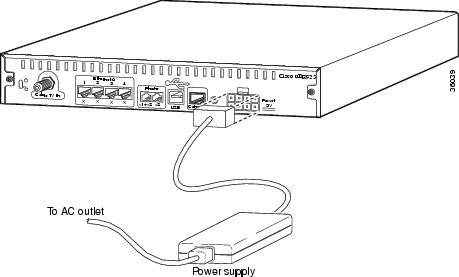
Connecting Power
This section describes how to connect the Cisco uBR925 cable access router to power using the AC-input power supply.
Warning
To connect AC-input power to the Cisco uBR925 cable access router:
Step 1
Step 2
Step 3
Figure 3-1 Connecting the Power Cord
Step 4
Step 5
Step 6
Caution
Warning
Warning
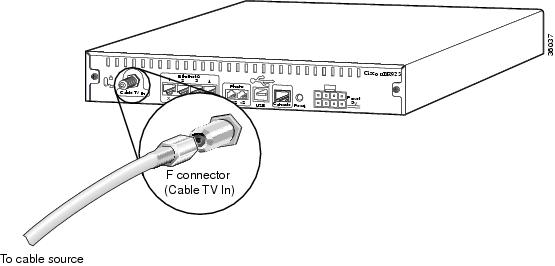
Connecting to the Cable System
To connect the Cisco uBR925 cable access router to the cable system:
Step 1
Step 2
Step 3
Step 4
Figure 3-2 Connecting the CATV Coaxial Cable to the Cisco uBR925 Cable Access Router
Caution
Step 5
Note
Caution
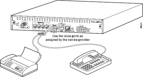
Connecting to Telephones or Fax Devices
If you have purchased voice services from your service provider, use the following procedure to connect the Cisco uBR925 cable access router to telephone or fax devices at the site.
Step 1
Step 2
Note
Step 3
Step 4
Caution
See Figure 3-3 illustrates a possible configuration. The exact configuration depends on the phone numbers that are assigned by the service provider.
Figure 3-3 Connecting the Voice Ports
Note
Step 5
Caution
Warning
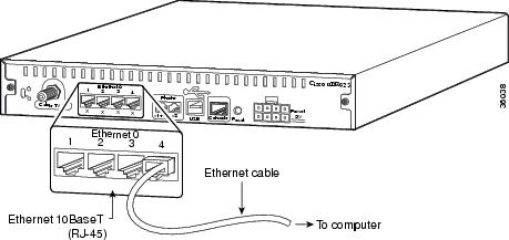
Connecting to the Computer (Ethernet)
This section describes how to connect the Cisco uBR925 cable access router to a computer using the Ethernet interface. If supported by the service provider, you can also connect an Ethernet hub to the cable access router, and then connect multiple computers to the Ethernet hub.
If you are not using the Ethernet interface, proceed to the "Connecting to the Computer (USB)" section.
Note
To connect the Cisco uBR925 cable access router to computers and other CPE devices at the site:
Step 1
•
•
Step 2
Figure 3-4 Connecting the Ethernet Cable to the Cisco uBR925 Cable Access Router
Note
Step 3
Step 4
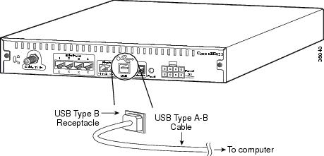
Connecting to the Computer (USB)
This section describes how to connect Cisco uBR925 cable access router to a computer using the Universal Serial Bus (USB) interface. (If you are not using the USB interface, complete the "Connecting to the Computer (Ethernet)" section before proceeding.)
Step 1
Note
Step 2
Step 3
Step 4
Figure 3-5 Connecting the USB Cable to the Cisco uBR925 Cable Access Router
Step 5
Step 6
Note
Router Power On and Initialization Sequence
When the Cisco uBR925 cable access router is connected and powered on, it runs automatic self-diagnostic and installation procedures. The following procedure describes what you should see during this process.
Note
While the Cisco uBR925 cable access router initializes:
Step 1
Step 2
Note
Step 3
Step 4
•
•
•
•
Step 5
•
•
•
•
Step 6
Step 7
Step 8
Verifying Installation
Use the following procedure to verify Internet connectivity between the PCs connected to the router's Ethernet ports and the Internet access provided by the CMTS. See "Troubleshooting," if any problems occur.
Step 1
Step 2
Step 3
Step 4
Step 5
Step 6
Note
If you install a cable access router at a time of year when the temperature is warmer, this step might assist you in determining how the cable access router will function over time. If the router does not function properly with the addition of attenuation, you should replace and reconfigure the coaxial cables at the subscriber site.Step 7
Step 8
Step 9
Step 10