[an error occurred while processing this directive]

Support

Chapter 4 - Voice over IP (VoIP) Configurations

 Feedback

Table Of Contents

Voice over IP Configurations

Overview

Introduction

Voice Handling

Quality of Service Support

H.323v2 Protocol

SGCP and MGCP Protocol Stack

H.323v2 Static Bridging Configuration

H.323v2 Static Routing Configuration

H.323v2 Dynamic Mapping Configuration

SGCP Configuration

MGCP Configuration


Voice over IP Configurations


This chapter provides an overview of Voice over IP (VoIP) operations on the Cisco uBR924 cable access router. It also describes how to configure the Cisco uBR924 router for basic VoIP operation in both bridging and routing modes. This chapter contains the following sections:

Overview

H.323v2 Static Bridging Configuration

H.323v2 Static Routing Configuration

H.323v2 Dynamic Mapping Configuration

SGCP Configuration

MGCP Configuration


Note The configurations shown in this chapter can be combined with most of the data-only configurations shown in "Advanced Data-Only Configurations." All voice configurations assume that the CMTS and associated servers, gateways, and gatekeepers have been configured accordingly.


Overview

When using a Cisco IOS image that contains voice support, the Cisco uBR924 cable access router supports Voice over IP (VoIP), which transmits voice and fax calls over a TCP/IP network such as the Internet. Depending on the services purchased from the cable service provider, subscribers can place and receive calls without using the local telco exchange carrier.

The Cisco uBR924 router has two voice ports that support two simultaneous voice and fax calls from each subscriber site, but multiple telephones and fax devices can be connected to each of the two VoIP telephone lines (provided that the 5 REN limit for each telephone line is not exceeded). Telephones at each subscriber site must support touch-tone dialing; rotary dialing is not supported. Special telephone features such as call waiting, forwarding, and conferencing are supported only when using Cisco IOS images that support those features.


Note Fax devices—standard Group III and computer-based Group III machines up to 14,400 baud—are supported in Cisco IOS Release 12.0(5)T and higher images that support VoIP. However, in general, fax/modem cards are not supported over VoIP links. You must be using a Cisco IOS image that supports voice and have purchased the appropriate feature license before being able to make voice calls using the Cisco uBR924 router.


Introduction

The Cisco uBR924 router uses packets to transmit and receive digitized voice over an IP network. Voice traffic is supported in both the DOCSIS-bridging and routing modes.


Note When the router is acting in DOCSIS-bridging mode, a voice call originating from the router's Ethernet interface cannot terminate on another device attached to that same Ethernet interface; it must terminate on a device that is reached through the cable interface. The router must be operating in routing mode to allow calls to both originate and terminate on the Ethernet interface.


Voice signals are packetized and transported in compliance with the following protocols:

H.323v2—Second version of an International Telecommunications Union (ITU) standard that specifies call signaling and control protocols for an IP data network. Supported on Cisco IOS Release 12.0(4)XI and higher voice images.

Simple Gateway Control Protocol (SGCP) Version 1.1—A signaling protocol under review by the Internet Engineering Task Force (IETF). Supported on Cisco IOS Release 12.0(7)T and higher voice images.

Media Gateway Control Protocol (MGCP) Version 0.1—A proposed IETF voice control protocol intended to eventually supersede the existing SCGP 1.1 protocol. Supported on Cisco IOS Release 12.1(3)T and higher voice images.


Note In Cisco IOS Release 12.1(3)T, the MGCP 0.1 and SGCP 1.1 protocols have been merged on the Cisco uBR924 router so that the router can respond efficiently to either protocol. The MGCP and SGCP protocols cannot be used if the H.323v2 protocol is used.


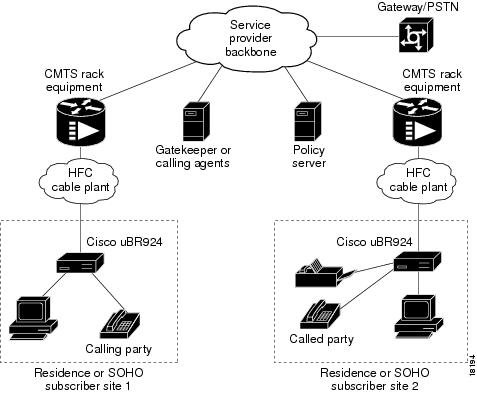
Figure 4-1 illustrates a broadband cable system that supports VoIP transmission.

Figure 4-1 Simplified VoIP Network

The CMTS at the headend routes IP telephony calls from the point of origination to the destination, transmitting them along with other traffic (both voice and data). To route voice calls across the local IP network to a destination on the Internet or the public switched telephone network (PSTN), the Cisco uBR924 router and CMTS deploy IP telephony as a local-loop bypass service. One of the following routing methods is then used, depending on the protocol being used:

If using H.323v2, the Cisco uBR924 acts as the H.323v2 gateway that forwards the voice packets to the CMTS, which then sends them to a telephony gatekeeper. The gatekeeper transmits the packets to their ultimate destination.

If using SGCP or MGCP, the Cisco uBR924 router acts as the residential gateway that forwards the voice packets to the CMTS, which then connects to the external call agent (SGCP or MGCP) or media gateway controller (MGCP). The call agent or controller determines how to transmit the call across the network to the trunking gateway that will be its ultimate destination.

The gateway at the destination typically interconnects the IP network to the public switched telephone network (PSTN) so that calls can be made to any phone, not just those that are part of the IP telephony network.

Voice calls are digitized, encoded, compressed, and packetized in an originating gateway; and then, decompressed, decoded, and reassembled in the destination gateway. A server maintains subscriber profiles and policy information. See the Cisco service provider voice documentation set if you have Cisco gatekeeper, gateway, or other applicable products.


Caution In certain countries, the provisioning of voice telephony over the Internet or use of these products may be prohibited and/or subject to laws, regulations or licenses, including requirements applicable to the use of the products under telecommunications and other laws and regulations; customer must comply with all such applicable laws in the country where the customer intends to use the product.

Voice Handling

With IP telephony, telephone calls can be delivered at rates as low as 8 kbps in a packet format using compression algorithms. Depending on the software release used, the Cisco uBR924 cable access router supports the following algorithms:

G.711 A-Law—64000 bps PCM uncompressed encoding, using the A-Law standard used in most of the world except for North America and a few other countries.

G.711 Mu-Law—64000 bps PCM uncompressed encoding, using the Mu-Law standard used in North America and a few other countries.

G.729—8000 bps compressed CS-ACELP encoding (default for telephone calls).


Caution Because voice is delay-sensitive, a well-engineered network is critical. Fine-tuning your network to adequately support VoIP typically involves a series of protocols and features geared to support QoS.

To achieve acceptable voice quality and reduce network bandwidth usage, several voice processing techniques are used. Digital Signal Processors (DSPs) provide the stream-to-packet and packet-to-stream conversion, as well as voice processing capabilities. Typical voice processing services include echo cancellation, voice compression, Voice Activity Detection (VAD) or silence compression, and Dual Tone Multi-Frequency (DTMF) tone detection and generation.

Quality of Service Support

Data traffic typically is sent only on a "best effort" basis, and if a packet is lost or delayed, it can be easily retransmitted without significantly affecting the connection. Such delays and losses are unacceptable, however, for real-time traffic such as voice calls.

For this reason, the CMTS and Cisco uBR924 router assign separate service identifiers (SIDs) for the voice and data traffic flows. Each SID has a separate class of service (CoS) that determines how its traffic flow is handled, allowing voice traffic to have a higher priority than the data traffic.

The CMTS and router can use different traffic shaping mechanisms to ensure that the higher priority voice traffic always has the bandwidth it needs. This allows voice calls (and other real-time traffic) to share the same channel as data traffic, without the quality of the voice calls being degraded by bursty data transmissions.


Note Separate CoS flows are available only when the router is connected to a CMTS that supports multiple classes of service per router. In addition, the router's configuration file must enable multiple classes of service.

The DOCSIS 1.0 specification does not support multiple CoS flows, so this flow technique is not available when the Cisco uBR924 router interoperates with a DOCSIS 1.0 CMTS. In this situation, voice and data traffic are both transmitted on a "best effort" basis. This may cause poorer voice quality and lower data throughput when calls are being made from the router's telephone ports.


The Cisco uBR924 router supports the following service classes:

The first CoS in the router's configuration file is configured as the "Tiered Best Effort Type Class" and is the default CoS for data traffic. The class has no minimum upstream rate specified for the channel.

This service class is assigned to the primary SID for the router. In addition to being used for data traffic, the router uses this SID for all MAC message exchanges with the CMTS, as well as for SNMP management traffic.

All traffic using this SID is transmitted on a "best effort" basis, but data traffic within this class can be prioritized into eight different priority levels; although all data traffic still has lower priority than the voice traffic, this allows certain data traffic (such as MAC messages) to be given higher priority than other data traffic. The CMTS system administrator defines the traffic priority levels and must include the traffic priority fields in the configuration file downloaded to the Cisco uBR924.

The second and third CoS are for the first and second voice ports, respectively, which are assigned to the secondary SIDs used for the voice ports. If using a Cisco IOS image that supports dynamic multi-SID assignment, these secondary SIDs are automatically created when a call is placed from one of the voice ports; when the call terminates, the secondary SID associated with it is deleted. If the Cisco IOS image does not support multi-SIDs, static SIDs are created for each of the voice ports during the power-on provisioning process, permanently reserving the bandwidth needed for the voice traffic.

The CMTS system administrator typically configures these secondary classes of service so that they have higher QoS classes for use by higher priority voice traffic. These classes should also have a minimum upstream data rate specified for the channel to guarantee a specific amount of bandwidth for the corresponding traffic flows. When static SIDs are used, that bandwidth is always reserved for voice calls; however, when dynamic multi-SID assignment is used, that bandwidth is reserved only when the voice calls are active.

H.323v2 Protocol

In architectures using the VoIP H.323v2 protocol stack, the session application manages two call legs for each call: a telephony leg managed by the voice telephony service provider and the VoIP leg managed by the cable system operator—the VoIP service provider. Use of the H.323v2 protocol typically requires a dial plan and mapper at the headend or other server location to map IP addresses to telephone numbers.

When both legs of the call have been setup, the session application creates a conference between them. The opposite leg's transmit routine for voice packets is given to each provider. The CMTS router passes data to the gateway and gatekeeper. The H.323v2 protocol stack provides signaling via H.225 and feature negotiation via H.245.


Note For more information on using H.323v2, see the document H.323 Version 2 Support, available on CCO and the Documentation CD-ROM.


To make and receive H.323 calls, the Cisco uBR924 router must be configured for the following:

The IP address of the gateway for the destination dialed—In Cisco uBR924 IOS Release 12.0(4)XI or higher interim builds, configure these IP addresses statically via the command-line interface (CLI) using voip dial peer group commands. When running Cisco IOS Release 12.0(5)T or higher interim images on Cisco gatekeeper products, the router obtains these addresses dynamically from the gatekeeper using the Registration, Admission, and Status (RAS) protocol.

The telephone numbers of the attached devices—In Cisco IOS Release 12.0(4)XI or higher interim builds, you configure these IP addresses statically via the CLI pots port commands. When using Cisco Network Registrar (CNR) version 3.0 or higher with the relay.tcl and setrouter.tcl scripts, and Cisco gatekeeper products in your network running Cisco IOS Release 12.0(5)T or higher images, you can obtain these addresses dynamically from CNR. The telephone numbers of attached devices are then sent in DHCP response messages. When the Cisco uBR924 processes the DHCP response, it automatically creates the pots dial peer for each port, creates the voip dial peer for the RAS target, and starts the H.323v2 RAS gateway support.


Note To support voice configurations involving Cisco gatekeeper products using RAS, Cisco IOS Release 12.0(5)T or higher images with gatekeeper support are required. The headend must have IP multicast enabled. The cable interface must be designated as the default for RAS to discover the gatekeeper. The gatekeeper then resolves all dialed destinations sent to the RAS protocol.


SGCP and MGCP Protocol Stack

When using a Cisco IOS Release 12.0(5)T or higher image with voice support, the Cisco uBR924 router supports the Simple Gateway Control Protocol (SGCP). When using a Cisco IOS Release 12.1(3)T or higher image with voice support, the Cisco uBR924 router also supports the MGCP protocol, which is intended to eventually supersede the SGCP protocol. Both MGCP and SGCP are signaling protocols that interact with a remote call agent (CA) to provide call setup and teardown for VoIP calls.

Using the call agent, SGCP and MGCP communicate with the voice gateways, dynamically resolving and routing calls. This creates a distributed system that enhances performance, reliability, and scalability while still appearing as a single VoIP gateway to external clients.

The remote call agent also provides the signaling and feature negotiation that would otherwise be provided by the Cisco uBR924 router when using the H.323v2 protocol. Similarly, the call agent also provides the mapping of IP addresses to telephone numbers, eliminating the dial plan mapper and static configurations that are required on the router when using the H.323v2 protocol.

The SGCP and MGCP protocols implement the gateway functionality using both trunk and residential gateways. The Cisco uBR924 router functions in this mode as a residential gateway with two endpoints.

SGCP and MGCP can preserve Signaling System 7 (SS7) style call control information as well as additional network information such as routing information and authentication, authorization, and accounting (AAA) security information. SGCP and MGCP allow voice calls to originate and terminate on the Internet, as well as allowing one end to terminate on the Internet and the other to terminate on a telephone on the PSTN.


Note The Cisco uBR924 cable access router supports both H.323 and SGCP/MGCP call control, but only one method can be active at a time.


H.323v2 Static Bridging Configuration

When the Cisco uBR924 router is running in DOCSIS-bridging mode and using a Cisco IOS image with voice support, it can route voice calls using an H.323v2 static dialing map. This requires the following minimum configuration:

Create a local dial peer for each voice port that will receive incoming calls. This requires configuring each voice port on the router with the phone numbers for the devices attached to those voice ports. The Cisco uBR924 router uses these numbers to determine which voice port should receive the call. Typically, the complete phone number or extension is specified for each port; when the Cisco uBR924 router receives an incoming call, all digits in the number are matched and stripped off, and the voice port is connected to the call.

Note The voice ports on the Cisco uBR924 router support only FXS devices.

Configure a remote dial peer for each possible destination for outgoing calls. This requires specifying the phone number(s) for the destination devices. Use the following guidelines for what numbers to enter:

For a single telephony device, such as a one-line phone or fax machine, enter the complete phone number or extension.

To direct a group of numbers to a specific destination—such as the extensions used on a remote PBX—enter a pattern matching the prefix used for those lines; asterisks can be used to match any number of digits and a period matches a single digit. For example, "572*" matches any phone numbers starting with 572 while "572." matches the numbers 5720-5729.

You must also specify the IP address for the destination host that will deliver the call to the telephony device (or if the destination device is an IP telephone, the IP address for that telephone). You can optionally specify an IP precedence level for the type of service (ToS) bits in the IP header to signify that these voice packets should be given higher priority in transit across the IP network.

If not being done by the CoS, you can also specify which coding/decoding (CODEC) algorithm should be used.

These functions are done using the dial-peer command, as shown in the following table:

 
Command
Purpose

Step 1 

To configure incoming calls on voice port V1:

uBR924(config)# dial-peer voice id-number pots

Specify a unique id-number for this incoming dial-peer and enter dial-peer configuration mode.

Step 2 

uBR924(config-dial-peer)# destination-pattern digits

Specify the telephone number(s) associated with this voice port.

Step 3 

uBR924(config-dial-peer)# port 0

Specify that voice port V1 is attached to this telephony equipment.

Step 4 

uBR924(config-dial-peer)# dtmf-relay [cisco-rtp] [h245-signal] [h245-alphanumeric]

Optionally configure the dial peer to support out of band signaling of DTMF tones.

Step 5 

uBR924(config-dial-peer)# exit

Exit dial-peer configuration mode.

Step 6 

To configure incoming calls on voice port V2:

uBR924(config)# dial-peer voice id-number pots

Specify a unique id-number for this incoming dial-peer and enter dial-peer configuration mode.

Step 7 

uBR924(config-dial-peer)# destination-pattern digits

Specify the telephone number(s) associated with this voice port.

Step 8 

uBR924(config-dial-peer)# port 1

Specify that voice port V2 is attached to this telephony equipment.

Step 9 

uBR924(config-dial-peer)# dtmf-relay [cisco-rtp] [h245-signal] [h245-alphanumeric]

Optionally configure the dial peer to support out of band signaling of DTMF tones.

Step 10 

uBR924(config-dial-peer)# exit

Exit dial-peer configuration mode.

Step 11 

Repeat for each possible outgoing destination:

uBR924(config)# dial-peer voice id-number voip

Specify a unique id-number for this outgoing dial-peer and enter dial-peer configuration mode.

Step 12 

uBR924(config-dial-peer)# destination-pattern digits

Specify the telephone number(s) associated with this dial-peer.

Step 13 

uBR924(config-dial-peer)# session target [ ipv4:ipaddress | dns:hostname ]

Specify the destination IP address or hostname for this dial-peer. This could be the IP address or hostname for either an IP telephone or another router or host providing voice services.

Step 14 

uBR924(config-dial-peer)# ip precedence number

(Optional) Specify an IP packet precedence level (1-5) for packets carrying calls to this dial peer (1-5, where 5 is the highest precedence for normal IP flows).

Step 15 

uBR924(config-dial-peer)# code [ g711alaw | g711ulaw | g729r8 ]

(Optional) Specify the codec algorithm to be used for these calls. The default is g711r8 (8Kbps compression; A-Law and Mu-Law are 64Kbps compression).

Step 16 

uBR924(config-dial-peer)# dtmf-relay [cisco-rtp] [h245-signal] [h245-alphanumeric]

Optionally configure the dial peer to support out of band signaling of DTMF tones.

Step 17 

uBR924(config-dial-peer)# exit

Exit dial-peer configuration mode.

Step 18 

uBR924# copy running-config startup-config
Building configuration...

Save the configuration to nonvolatile memory so that it will not be lost in the event of a reset, power cycle, or power outage.

Step 19 

uBR924# show startup-config

Display the configuration file that was just created.


Note The ID numbers assigned using the dial-peer voice command must be unique but they are local to the Cisco uBR924 router. These numbers are used only when configuring each particular dial peer and have no meaning when dialing numbers or routing calls.


The following example shows a Cisco uBR924 router set up to support bridging and a static H.323 dial map with the following characteristics:

Voice port V1 is connected to a telephony device that receives calls for the number 4123.

Voice port V2 is connected to a telephony device that receives calls for the number 4124.

Outgoing calls to the numbers 6000—6999 are routed to the dial peer at IP address 10.1.71.65.

Outgoing calls to the numbers 7000—7999 are routed to the dial peer at IP address 10.1.71.75. These calls are sent with an IP ToS precedence of "5" and using the G.711 Mu-law codec algorithm.

The commands that set up the H.323v2 dial map are shown in bold:

version 12.1
no service pad
service timestamps debug uptime
service timestamps log uptime
no service password-encryption
!
hostname ubr924
!
clock timezone - 3
ip subnet-zero
no ip routing
!
!
 voice-port 0
 input gain -3
!
voice-port 1
 input gain -3
!
dial-peer voice 1 pots 
 destination-pattern 4123 
 port 0 
! 
dial-peer voice 2 pots 
 destination-pattern 4124 
 port 1 
! 
dial-peer voice 1001 voip 
 destination-pattern 6... 
 session target ipv4:10.1.71.65 
 dtmf-relay cisco-rtp h245-signal h245-alphanumeric 
! 
dial-peer voice 1002 voip 
 destination-pattern 7... 
 ip precedence 5 
 codec g711ulaw 
 session target ipv4:10.1.71.75 
 dtmf-relay cisco-rtp h245-signal h245-alphanumeric 
!
!
interface Ethernet0
 no ip directed-broadcast
 no ip route-cache
 bridge-group 59
 bridge-group 59 spanning-disabled
!
interface cable-modem0
 ip address dhcp
 no ip directed-broadcast
 no ip route-cache
 cable-modem downstream saved channel 537000000 26
 bridge-group 59
 bridge-group 59 spanning-disabled
!
!
ip classless
no ip http server
no service finger
!
!
line con 0
 exec-timeout 0 0
 transport input none
line vty 0 4
 login
end

H.323v2 Static Routing Configuration

When the Cisco uBR924 router is operating in routing mode, the configuration of an H.323v2 static dial map uses the same commands as those given in the "H.323v2 Static Bridging Configuration" section. The only difference is that calls can terminate and originate on the Ethernet interface, which is not possible in DOCSIS-bridging mode.

The following sample configuration shows a Cisco uBR924 router set up for a static H.323v2 dial map with the following characteristics:

Local dial peer 1 specifies that voice port V1 is connected to a telephone or fax machine with the number 6101.

Local dial peer 2 specifies that voice port V2 is connected to a telephone or fax machine with the number 6102.

Remote dial peer 101 specifies that calls to numbers 6200-6299 should be routed to IP address 10.1.71.62.

Remote dial peers 102 and 103 specify that calls to numbers 6101 and 6102 should be routed to IP address 24.1.61.5, which is the IP address for the Cisco uBR924 router's Ethernet interface. This allows the router to complete calls between voice ports V1 and V2.

The commands related to the dial map are in bold.

version 12.1
no service pad
service timestamps debug uptime
service timestamps log uptime
!
hostname ubr924
!
!
!
class-map class-default
 match any 
!
!
!
clock timezone - 3
ip subnet-zero
!
!
!
!
voice-port 0
!
voice-port 1
!
dial-peer voice 1 pots 
 destination-pattern 6101 
 port 0 
! 
dial-peer voice 2 pots 
 destination-pattern 6102 
 port 1 
! 
dial-peer voice 101 voip 
 destination-pattern 62.. 
 session target ipv4:10.1.71.62 
 dtmf-relay cisco-rtp 
! 
dial-peer voice 102 voip 
 destination-pattern 6101 
 session target ipv4:24.1.61.5 
! 
dial-peer voice 103 voip 
 destination-pattern 6102 
 session target ipv4:24.1.61.5 
 dtmf-relay cisco-rtp 
!
!
interface Ethernet0
 ip address 24.1.61.1 255.255.255.0
 no ip directed-broadcast
 no ip mroute-cache
!
interface cable-modem0
 ip address dhcp
 no ip directed-broadcast
 no ip mroute-cache
 cable-modem downstream saved channel 537000000 27
 no cable-modem compliant bridge
!
router rip
 version 2
 network 10.0.0.0
 network 24.0.0.0
 no auto-summary 
!
no ip classless
ip route 0.0.0.0 0.0.0.0 10.1.71.1
no ip http server
no service finger
!
!
line con 0
 exec-timeout 0 0
 transport input none
line vty 0 4
 login
!
!
end

Note The above configuration assumes that the DHCP server assigns an IP address to the cable interface that is in the class A private network (10.0.0.0).


H.323v2 Dynamic Mapping Configuration

When using a Cisco IOS image that supports voice, the Cisco uBR924 router supports using the Registration, Admission, and Status (RAS) protocol to allow a remote gatekeeper to translate phone numbers (E.164 addresses) to the IP addresses of specific dial peers. This allows the gatekeeper to maintain a central database of dial peers, so that this information does not have to be entered into static dial maps on every router that is acting as a voice gateway.


Note The Cisco uBR924 router can use H.323v2 dynamic mapping in either DOCSIS-bridging mode or routing mode.


The example shown in this section assumes that Cisco Network Registrar (CNR) version 3.0 or higher is being used as the DHCP server. CNR assigns the E.164 addresses to local voice ports and uses DHCP to define the E.164 addresses-to-port assignments.

The gatekeeper can be a Cisco router, such as the Cisco 3620, with a Cisco IOS image that supports the gatekeeper function. The Cisco uBR924 router acts as the H.323v2 gateway and creates the dial peers, starts H.323 RAS gateway support, and registers the E.164 addresses with the gatekeeper. The gatekeeper resolves the remote peers' IP addresses when the router sends a request using RAS.


Note Support for RAS and H.323v2 in Cisco gatekeeper products is found in Cisco IOS Release 12.0(5)T or higher. Support for multiple classes of service when using Cisco uBR7200 CMTS equipment is found in Cisco 12.0(4)XI or higher.

If you are not using CNR or Cisco gatekeeper products running Cisco IOS Release 12.0(5)T software, use a static dial-map as shown in the previous H.323 configurations ("H.323v2 Static Bridging Configuration" and "H.323v2 Static Routing Configuration").


You must do the following to configure the Cisco uBR924 router for dynamic mapping:

Configure the local dial-peers—This is done in the same way as for a static H.323v2 dial map.

Configure the remote dial-peers—This is done in the same way as for a static H.323v2 dial map, except that instead of specifying a target IP address or host name, you specify ras as the target.

Enable the VoIP gateway function using the gateway global configuration command.

Configure the cable modem interface to be the gateway interface.

These functions are done using the commands shown in the following table:

 
Command
Purpose

Step 1 

To configure incoming calls on voice port V1:

uBR924(config)# dial-peer voice id-number pots

Specify a unique id-number for this incoming dial-peer and enter dial-peer configuration mode.

Step 2 

uBR924(config-dial-peer)# destination-pattern digits

Specify the telephone number(s) associated with this voice port.

Step 3 

uBR924(config-dial-peer)# port 0

Specify that voice port V1 is attached to this telephony equipment.

Step 4 

uBR924(config-dial-peer)# dtmf-relay [cisco-rtp] [h245-signal] [h245-alphanumeric]

Optionally configure the dial peer to support out of band signaling of DTMF tones.

Step 5 

uBR924(config-dial-peer)# exit

Exit dial-peer configuration mode.

Step 6 

To configure incoming calls on voice port V2:

uBR924(config)# dial-peer voice id-number pots

Specify a unique id-number for this incoming dial-peer and enter dial-peer configuration mode.

Step 7 

uBR924(config-dial-peer)# destination-pattern digits

Specify the telephone number(s) associated with this voice port.

Step 8 

uBR924(config-dial-peer)# port 1

Specify that voice port V2 is attached to this telephony equipment.

Step 9 

uBR924(config-dial-peer)# dtmf-relay [cisco-rtp] [h245-signal] [h245-alphanumeric]

Optionally configure the dial peer to support out of band signaling of DTMF tones.

Step 10 

uBR924(config-dial-peer)# exit

Exit dial-peer configuration mode.

Step 11 

Repeat for each possible outgoing destination:

uBR924(config)# dial-peer voice id-number voip

Specify a unique id-number for this outgoing dial-peer and enter dial-peer configuration mode.

Step 12 

uBR924(config-dial-peer)# destination-pattern digits

Specify the telephone number(s) associated with this dial-peer.

Step 13 

uBR924(config-dial-peer)# session target ras

Specify that RAS will be used to resolve the destination for the dial-peer.

Step 14 

uBR924(config-dial-peer)# dtmf-relay [cisco-rtp] [h245-signal] [h245-alphanumeric]

Optionally configure the dial peer to support out of band signaling of DTMF tones.

Step 15 

uBR924(config-dial-peer)# exit

Exit dial-peer configuration mode.

Step 16 

uBR924(config)# gateway

Enable the VoIP gateway on the Cisco uBR924 router.

Step 17 

uBR924(config)# interface cable-modem 0

Enter interface configuration mode for the cable interface.

Step 18 

uBR924(config-if)# (enter appropriate cable interface configuration commands)

Enter whatever commands are needed to configure the cable interface such as IP address, downstream channel, whether DOCSIS-bridging is enabled, and so forth.

Step 19 

uBR924(config-if)# h323-gateway voip interface

Specify that the cable interface is the H.323 Gateway VoIP interface.

Step 20 

uBR924(config-if)# h323-gateway voip id gatekeeper-id ipaddr IP-address port-number

Identify the RAS gatekeeper by specifying its gatekeeper ID (which must match the ID configured on the gatekeeper), its IP address, and the port number which services gateway requests.

Step 21 

uBR924(config-if)# h323-gateway voip h323-id interface-id

Specify the H.323 ID for this interface. This ID is any string that uniquely identifies this gateway to the gatekeeper. Typically, this is the gateway's name and domain (such as "ubr924@cisco.com").

Step 22 

uBR924(config-if)# h323-gateway voip tech-prefix prefix

(Optional) Specify a technology prefix to identify the type of service this gateway can provide. If more than one service is being provided, give this command for each separate technology prefix. (The prefix is defined at the gatekeeper and can up to 11 characters long, with the pound sign (#) as the last character.)

Step 23 

uBR924(config-if)# exit

Exit interface configuration mode.

Step 24 

uBR924# copy running-config startup-config
Building configuration...

Save the configuration to nonvolatile memory so that it will not be lost in the event of a reset, power cycle, or power outage.

Step 25 

uBR924# show startup-config

Display the configuration file that was just created.


Note For additional information on the gateway configuration commands, see the document Configuring H.323 VoIP Gateway for Cisco Access Platforms, available on CCO and the Document CD-ROM.


The following configuration shows a Cisco uBR924 router configured for routing mode and using RAS dynamic mapping with the following characteristics:

The router's V1 voice port is connected to a telephone or fax machine with the number 1000, and the V2 voice port is connected to a telephone or fax machine with the number 1001.

Four remote dial-peers are configured, with the numbers 1000, 1001, 2000, and 2001. All use the G.711 Mu-Law CODEC and the RAS protocol is used to resolve their number-address mapping. (The local dial-peer numbers, 1000 and 1001 are included as remote dial-peers to allow the router to forward calls between the two local dial-peers, as well as between local and remote dial-peers; the router must be in routing mode to support this.)

The cable interface is configured as the gatekeeper interface, using the gatekeeper named gatekeeper3620 at the IP address 10.1.70.50 and at port 1719. The router identifies itself as the gateway named uBR924 with a tech-prefix of 1#.

The commands related to the dial mapping are in bold.

version 12.1
service config
no service pad
service timestamps debug uptime
service timestamps log uptime
no service password-encryption
!
hostname uBR924
!
clock timezone - 4
ip subnet-zero
ip host-routing
!
voice-port 0
!
voice-port 1
!
dial-peer voice 1 pots 
 destination-pattern 1000 
 port 0 
! 
 dial-peer voice 2 pots 
 destination-pattern 1001 
 port 1 
! 
dial-peer voice 10 voip 
 destination-pattern 1001 
 codec g711ulaw 
 session target ras 
! 
dial-peer voice 20 voip 
 destination-pattern 1000 
 codec g711ulaw 
 session target ras 
! 
dial-peer voice 30 voip 
 destination-pattern 2000 
 codec g711ulaw 
 session target ras 
! 
dial-peer voice 40 voip 
 destination-pattern 2001 
 codec g711ulaw 
session target ras 
! 
gateway 
!
!
interface Ethernet0
 ip address 24.1.0.1 255.255.0.0
 no ip directed-broadcast
 no ip mroute-cache
!
interface cable-modem0
 ip address dhcp
 no ip directed-broadcast
 no ip mroute-cache
 no keepalive
 cable-modem downstream saved channel 477000000 56
 no cable-modem compliant bridge
 h323-gateway voip interface 
 h323-gateway voip id gatekeeper3620 ipaddr 10.1.70.50 1719 
 h323-gateway voip h323-id uBR924 
 h323-gateway voip tech-prefix 1# 
! 
router rip
 version 2
 network 10.0.0.0
 network 24.0.0.0
!
ip classless
no ip http server
no service finger
!
!
line con 0
 transport input none
line vty 0 4
!
end

Note The above configuration assumes that the DHCP server assigns an IP address to the cable interface that is in the class A private network (10.0.0.0).


SGCP Configuration

When using Cisco IOS Release 12.0(7)T or higher and a software image that supports voice, the Cisco uBR924 router can use the SGCP protocol for routing voice calls. This transfers the dial mapping to an external call agent, so that the VoIP gateways do not have to be individually configured with the dial mappings.


Note The Cisco uBR924 router can use SGCP in either DOCSIS-bridging mode or routing mode.


You must do the following to configure the Cisco uBR924 router for a dynamic mapping configuration:

Enable SGCP operation on the Cisco uBR924 router.

Specify the SGCP call agent's IP address.

Configure the local dial-peers to be SCGP applications.

Optionally enable the sending of SNMP traps for SGCP.


Note No configuration of remote dial-peers is needed when using SGCP.


These functions are done using the commands shown in the following table:

 
Command
Purpose

Step 1 

To configure incoming calls on voice port V1:

uBR924(config)# dial-peer voice id-number pots

Specify a unique id-number for this incoming dial-peer and enter dial-peer configuration mode.

Step 2 

uBR924(config)# application SGCPAPP

Specify that this dial-peer is handled as an SGCP application.

Step 3 

uBR924(config-dial-peer)# destination-pattern digits

Specify the telephone number(s) associated with this voice port.

Step 4 

uBR924(config-dial-peer)# port 0

Specify that voice port V1 is attached to this telephony equipment.

Step 5 

uBR924(config-dial-peer)# exit

Exit dial-peer configuration mode.

Step 6 

To configure incoming calls on voice port V2:

uBR924(config)# dial-peer voice id-number pots

Specify a unique id-number for this incoming dial-peer and enter dial-peer configuration mode.

Step 7 

uBR924(config)# application SGCPAPP

Specify that this dial-peer is handled as an SGCP application.

Step 8 

uBR924(config-dial-peer)# destination-pattern digits

Specify the telephone number(s) associated with this voice port.

Step 9 

uBR924(config-dial-peer)# port 1

Specify that voice port V2 is attached to this telephony equipment.

Step 10 

uBR924(config-dial-peer)# exit

Exit dial-peer configuration mode.

Step 11 

ubr924(config)# sgcp

Enable SGCP operations on the router.

Step 12 

ubr924(config)# sgcp call-agent ip-address [ port ]

Specify the IP address and optional UDP port number for the SGCP call-agent. If no port number is given, the default of 2427 (the well-known SGCP port number) is used.

Step 13 

uBR924(config)# snmp-server enable traps xgcp

(Optional) If SNMP management is used for this router, specify that SGCP and related traps be sent to the SNMP manager.

Step 14 

uBR924# copy running-config startup-config
Building configuration...

Save the configuration to nonvolatile memory so that it will not be lost in the event of a reset, power cycle, or power outage.

Step 15 

uBR924# show startup-config

Display the configuration file that was just created.

The following configuration shows a Cisco uBR924 router configured in DOCSIS-bridging mode that uses SGCP for the routing of its voice calls. The relevant commands are shown in bold.

version 12.1
no service pad
service timestamps debug uptime
service timestamps log uptime
no service password-encryption
!
hostname ubr924
!
!
clock timezone - 0 6
ip subnet-zero
no ip routing
ip domain-name cisco.com
ip name-server 4.0.0.32
!         
sgcp 
sgcp call-agent 10.186.1.36 
! 
xgcp snmp sgcp
!
!
voice-port 0
!
voice-port 1
!
dial-peer voice 100 pots 
 application SGCPAPP 
 destination-pattern 5551212 
 port 0 
! 
dial-peer voice 101 pots 
 application SGCPAPP 
 destination-pattern 5551213 
 port 1 
! 
process-max-time 200
!
interface Ethernet0
 no ip directed-broadcast
 no ip route-cache
 no ip mroute-cache
 bridge-group 59
 bridge-group 59 spanning-disabled
!
interface cable-modem0
 ip address dhcp
 no ip directed-broadcast
 no ip route-cache
 no ip mroute-cache
 cable-modem downstream saved channel 699000000 27
 bridge-group 59
 bridge-group 59 spanning-disabled
!
ip classless
no ip http server
no service finger
!
!
line con 0
 transport input none
line vty 0 4
 login
!
end

MGCP Configuration

When using Cisco IOS Release 12.1(3)T and higher software images that support voice, the Cisco uBR924 router can use the MGCP protocol for routing voice calls. This transfers the dial mapping to an external call agent or to a Media Gateway Controller, so that the VoIP gateways do not have to be individually configured with the dial mappings.


Note The Cisco uBR924 router can use MGCP in either DOCSIS-bridging mode or routing mode.


You must do the following to configure the Cisco uBR924 router for MGCP routing of voice calls:

Enable MGCP operation on the Cisco uBR924 router.

Specify the MGCP call agent's IP address.

Configure the local dial-peers to be MCGP applications.

Optionally specify the MGCP packages to be supported.

Optionally change a number of MGCP parameters.


Note No configuration of remote dial-peers is needed when using MGCP.


These functions are done using the commands shown in the following table:

 
Command
Purpose

Step 1 

To configure incoming calls on voice port V1:

uBR924(config)# dial-peer voice id-number pots

Specify a unique id-number for this incoming dial-peer and enter dial-peer configuration mode.

Step 2 

uBR924(config)# application MGCPAPP

Specify that this dial-peer is handled as an MGCP application.

Step 3 

uBR924(config-dial-peer)# port 0

Specify that voice port V1 is attached to this telephony equipment.

Step 4 

uBR924(config-dial-peer)# exit

Exit dial-peer configuration mode.

Step 5 

To configure incoming calls on voice port V2:

uBR924(config)# dial-peer voice id-number pots

Specify a unique id-number for this incoming dial-peer and enter dial-peer configuration mode.

Step 6 

uBR924(config)# application MGCPAPP

Specify that this dial-peer is handled as an MGCP application.

Step 7 

uBR924(config-dial-peer)# port 1

Specify that voice port V2 is attached to this telephony equipment.

Step 8 

uBR924(config-dial-peer)# exit

Exit dial-peer configuration mode.

Step 9 

ubr924(config)# mgcp

Enable MGCP operations on the router.

Step 10 

ubr924(config)# mgcp call-agent ip-address [ port ] [ service-type sgcp | mgcp ]

Specify the IP address and optional UDP port number for the MGCP call-agent. If no port number is given, the default is 2427. The default service-type is mgcp, but sgcp can be specified to ignore RSIP error messages.

Step 11 

ubr924(config)# mgcp dtmf-relay { codec | low-bit-rate } mode { cisco | out-of-band }

(Optional) Enables the accurate forwarding of touchtone digits during a voice call. Use codec to specify the G.711 codec or low-bit-rate to specify the G.729 codec. Use a mode of cisco to transmit the tones with the Cisco proprietary method; if the remote gateway is not a Cisco router, use out-of-band instead.

Step 12 

ubr924(config)# mgcp ip-tos { high-reliability | high-throughput | low-cost | low-delay | precedence value }

(Optional) Enable IP Type of Services (TOS) for the voice connections, and specify the value for the IP precedence bit (the default IP precedence is 3).

Step 13 

ubr924(config)# mgcp max-waiting-delay value

(Optional) Specify the number of milliseconds to wait after a restart (default of 3000) before connecting with the call agent. If used, these values should be staggered among gateways to avoid having large numbers of gateways connecting with the call agent at the same time after a mass restart.

Step 14 

ubr924(config)# mgcp modem passthru { cisco | ca }

(Optional) Enable the transmission and reception of modem and fax data. If the remote gateway is a Cisco router, specify cisco; otherwise, specify ca (default) to allow the data to pass-through the call-agent.

Step 15 

ubr924(config)# mgcp package-capability { line-package | dtmf-package | gm-package | rtp-package }

(Optional) Specify that the Cisco uBR924 router supports a particular package capability. Give this command multiple times to enable multiple packages. Use this command before using the mgcp default-package command.

Step 16 

ubr924(config)# mgcp default-package { line-package | dtmf-package | gm-package }

(Optional) Specify the default package type for the media gateway; defaults to line-package.

Step 17 

ubr924(config)# mgcp playout { adaptive init-value min-value max-value | fixed init-value }

(Optional) Change the jitter buffer packet size in milliseconds for MGCP calls, using either an adaptive range or a fixed value. The default is adaptive 60 4 200.

Step 18 

ubr924(config)# mgcp request retries count

(Optional) Specify the number of times a call request message is transmitted to a call agent before timing out. The default is 3 times.

Step 19 

ubr924(config)# mgcp request timeout timeout

(Optional) Specify the number of milliseconds to wait for a response to a request before retransmitting or timing out the request. The default is 500 milliseconds.

Step 20 

ubr924(config)# mgcp restart-delay value

(Optional) Specify the value (in seconds) used in Restart in Progress (RSIP) messages to indicate the delay before the connection is torn down. The default delay is 0 seconds.

Step 21 

ubr924(config)# mgcp vad

(Optional) Enable Voice Activity Detection (VAD) to turn silence suppression on. The default disables VAD.

Step 22 

uBR924# copy running-config startup-config
Building configuration...

Save the configuration to nonvolatile memory so that it will not be lost in the event of a reset, power cycle, or power outage.

Step 23 

uBR924# show startup-config

Display the configuration file that was just created.

The following configuration shows a Cisco uBR924 router configured in DOCSIS-bridging mode that uses MGCP for controlling its voice calls. The relevant commands are shown in bold.

version 12.1
no service pad
service timestamps debug uptime
service timestamps log uptime
no service password-encryption
!
hostname ubr924
!
!
clock timezone - 0 6
ip subnet-zero
no ip routing
ip domain-name cisco.com
ip name-server 10.0.0.32
!         
 mgcp 
 mgcp call-agent 10.186.1.36 
 mgcp modem passthru ca 
 mgcp package-capability dtmf-package 
 mgcp package-capability line-package 
 mgcp default-package line-package 
! 
xgcp snmp sgcp
!
!
voice-port 0
!
voice-port 1
!
dial-peer voice 100 pots 
 application MGCPAPP 
 port 0 
! 
dial-peer voice 101 pots 
 application MGCPAPP 
 port 1 
! 
process-max-time 200
!
interface Ethernet0
 no ip directed-broadcast
 no ip route-cache
 no ip mroute-cache
 bridge-group 59
 bridge-group 59 spanning-disabled
!
interface cable-modem0
 ip address dhcp
 no ip directed-broadcast
 no ip route-cache
 no ip mroute-cache
 bridge-group 59
 bridge-group 59 spanning-disabled
!
ip classless
no ip http server
no service finger
!
!
line con 0
 transport input none
line vty 0 4
 login
!
end


[an error occurred while processing this directive]