Feedback Feedback
|
Table Of Contents
Through the Cable Interface when the Cable Interface is Operational
Through the Ethernet Interface when the Cable Interface is Not Operational
Using the Cable Monitor Tool
This appendix describes the Cisco uBR924 cable access router's Cable Monitor tool. The Cable Monitor is part of the router's onboard software that provides a web-based diagnostic tool for easy access to configuration and status information about the router, without requiring access to the router's command line interface (CLI).
Note
The Cable Monitor is available in Cisco IOS Release 12.1(1)T and later releases.
Technicians and subscribers can access the tool in the following ways:
•
•
The Cable Monitor operates in two modes:
•
•
Note
The following sections describe the Cisco uBR924 router's Cable Monitor:
Enabling the Cable Monitor
By default, the Cable Monitor is disabled. To allow technicians and subscribers to access the Cable Monitor, it must be enabled using the ip http global configuration command as follows:
Tip
When the Cable Monitor is enabled, it also automatically enables the Cisco web server (giving the equivalent of the ip http server command). However, while the Cable Monitor is active, it disables all other access to the Cisco web server, preventing the user from accessing the CLI commands that are normally available when the Cisco web server is active. When the Cable Monitor is active, the Cisco web server can be used only for displaying the Cable Monitor pages.
Note
Configuration Modes
The ip http cable-monitor basic command enables the Cable Monitor and puts it in basic mode. In this mode, the Cable Monitor displays information only about the router's current status, whether it has successfully completed all of its initialization routines, and cable performance statistics.
The ip http cable-monitor advance command enables the Cable Monitor and puts it in advanced mode. In this mode, the Cable Monitor displays the router's current status, the status of its initialization routines, the status of the voice ports, the router's basic configuration, and performance statistics. If an enable password is set, users who can supply the enable password can also view detailed debugging and troubleshooting configuration information; if an enable password is not set, all users can view this information.
Caution
By default, the Cable Monitor is configured with the IP address 192.168.100.1, which is a Class C address in the private IP address space reserved for private networks. If a device on the subscriber's private network is already using this IP address, use the URL-IP-address and URL-mask optional parameters to specify another IP address.
For example, to enable the Cable Monitor for advanced mode with the private IP address of 10.0.1.2 and the default HTTP port of 80, use the following command:
ip http cable-monitor advance 10.0.1.2 255.0.0.0
Note
Security Considerations
The Cable Monitor is a read-only tool that cannot be used to change the configuration of the Cisco uBR924 router. The debug page in advanced mode, however, does display information that could be used to defeat the router's security. This page is password-protected, requiring users to enter the enable password before displaying it; however, if an enable password has not been set, any user can display the debug page, which could reveal SNMP community strings and other configuration information.
For this reason, the following guidelines should be used when developing a security policy for the router:
•
•
Note
Disabling the Cable Monitor
To disable the Cable Monitor, use the ip http global configuration command as follows:
Note
When disabling the Cable Monitor, the console might display warning messages similar to the following:
% monitor-209.165.202.131 is not in the database.% monitor-192.168.100.1 is not in the database.% Range [209.165.202.131, 209.165.202.131] is not in the database.% Range [192.168.100.1, 192.168.100.1] is not in the database.These messages can be ignored because they are simply confirming that the IP addresses used for the Cable Monitor are no longer being used for that purpose.
Note
Accessing the Cable Monitor
The Cable Monitor can be accessed either through the cable interface (typically by technicians at the headend or the service provider's network operations center) or through the Ethernet interface (typically by subscribers when the cable interface has gone down). See the following sections for more information.
Note
Through the Cable Interface when the Cable Interface is Operational
During normal operations—when the Cisco uBR924 router is online and has connectivity with the CMTS through the cable interface—service technicians at the headend can access the Cable Monitor by doing the following:
Step 1
Step 2
For example, if the Cisco uBR924 router has been assigned the IP address of 209.165.202.131 by the service provider, a technician at the headend would use the following URL to access the Cable Monitor:
http://209.165.202.131
If a port number other than the default of 80 has been assigned to the Cable Monitor, that port number must be included as part of the URL. For example, if the Cisco uBR924 router has been assigned the IP address of 209.165.202.131 and a port number of 8080 by the service provider, a technician at the headend would use the following URL to access the Cable Monitor:
http://209.165.202.131:8080
Tip
Through the Ethernet Interface when the Cable Interface is Not Operational
When the Cisco uBR924 router loses connectivity with the CMTS at the headend and detects that its cable interface is not operational, the router automatically switches into a diagnostic mode and does the following:
•
•
Note
•
•
•
When the cable interface is down, users at the subscriber site can use the following procedure to access the Cable Monitor to aid in troubleshooting the problem with the cable network:
Step 1
Step 2
Note
Step 3
Step 4
Note
Step 5
Sample Pages
Table B-1 lists each of the web pages displayed by the Cable Monitor, the modes in which the pages are displayed, and a short description of each page's information.
The following sections describe each page in more detail.
Home Page
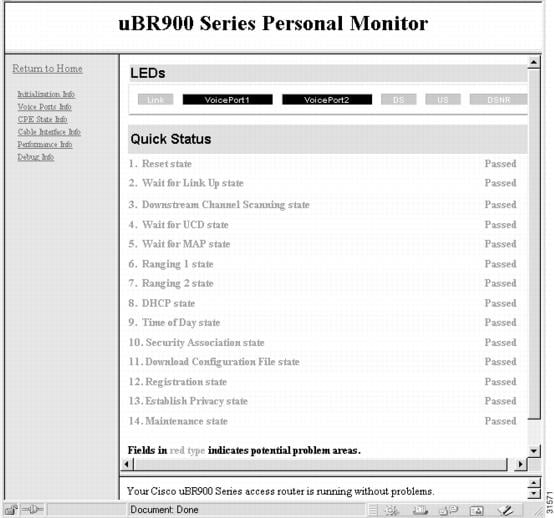
The Cable Monitor home page displays the current status of the LEDs on the front panel of the Cisco uBR924 router and summarizes the status of the router's registration process with the CMTS. Figure B-1 shows a typical home page when the Cable Monitor is configured for advanced mode.
Figure B-1 Cable Monitor Home Page
Note
The top of the Cable Monitor home page displays the current status of the LEDs on the front panel of the Cisco uBR924 router:
•
•
•
•
•
•
The Quick Status section of the home page summarizes the information that is displayed on the Initialization Information page, described in the next section.
Initialization Information
The Initialization Information page is available to advanced users only and displays the same information shown in the Quick Status section of the Home Page. This information summarizes the router's power-on initialization and registration process using the following color codes:
•
•
•
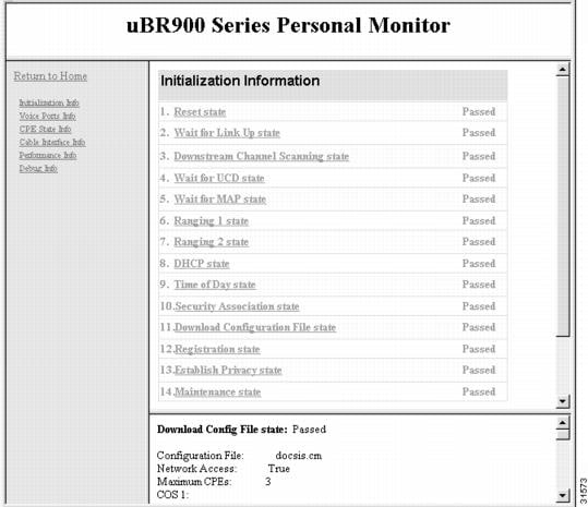
Figure B-2 shows a display for a Cisco uBR924 router that has successfully registered and come online.
Figure B-2 Initialization Information Page
This page provides detailed information on the state changes when the Cisco uBR924 router tries to establish communication and registration with the CMTS. All stages must show "Passed" before the router can come online.
Clicking on the name of the stage displays more information, if available, in the bottom half of the window. For example, clicking stage 11, "Download Configuration File state," displays the name of the configuration file that was downloaded to the router and the configuration parameters it contained.
The following is the normal progression of states that would be displayed if the Cisco uBR924 router registers successfully with the CMTS:
•
•
•
–
–
–
–
–
–
–
•
–
–
–
•
•
–
–
–
–
•
•
–
–
–
–
–
–
•
•
•
–
–
–
–
Assigned SID
Max Downstream Rate
Max Upstream Rate
Upstream Priority
Min Upstream Rate
Max Upstream Burst
Privacy Enable
Note
•
•
•
Voice Ports Information
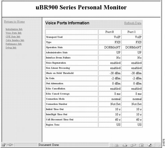
The Voice Ports Information page summarizes the current status of the two voice ports on the Cisco uBR924 router. Figure B-3 shows a typical Voice Ports Information page.
Figure B-3 Voice Ports Page
Note
The Voice Ports Information page displays the same information that is shown using the show voice port command:
•
–
–
•
•
–
–
–
–
–
–
•
–
–
–
•
•
•
•
•
•
•
•
•
•
•
•
•
•
CPE State Information
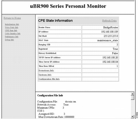
This page summarizes how the Cisco uBR924 router has been configured at the MAC (physical) layer. Figure B-4 shows a typical CPE State Information page.
Figure B-4 CPE State Information Page
The following information is shown in the CPE State Information page:
•
•
•
•
–
–
–
–
–
–
–
–
–
–
–
–
–
•
•
•
•
•
•
•
–
–
–
–
–
–
•
–
–
–
–
–
–
–
•
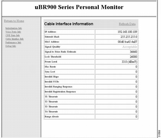
Cable Interface Information
The Cable Interface Information page provides information on the Cisco uBR924 router's cable interface and the quality of its signal. When the cable interface is not operational, the information provided is based on the live values last available.
Figure B-5 shows a typical Cable Interface page.
Figure B-5 Cable Interface Information Page
The following information is displayed on the Cable Interface page:
•
•
•
•
–
–
–
•
•
•
The following are errors encountered by the router at the MAC layer:
•
•
•
•
•
•
•
•
•
•
•
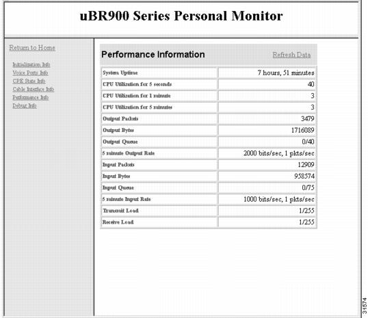
Performance Information
This page is available to all users and provides basic performance statistics for the Cisco uBR924 router. Figure B-6 shows a typical Performance Information page.
Figure B-6 Performance Information Page
The following information is displayed on the Performance Information page:
•
•
•
•
•
•
•
•
•
•
•
•
•
•
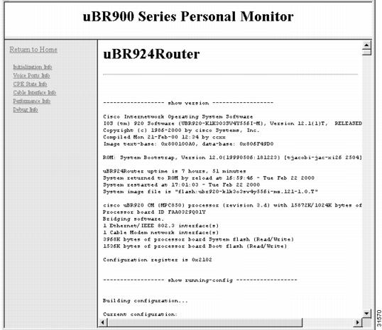
Debug Information Page
This page displays the output of the show tech-support command, which includes the output of the following CLI commands:
•
•
•
•
•
•
•
•
•
•
•
•
•
•
•
If an enable password has been set, the user must enter the level 15 user ID and password to access this page. If no enable password has been set, this page is accessible to all users.
Note
Figure B-7 shows a typical Debug Information page.
Figure B-7 Debug Information Page