簡介
本文檔介紹如何在Cisco Firepower 4145 NGFW裝置中配置主用/主用故障切換。
必要條件
需求
思科建議您瞭解以下主題:
- 思科自適應安全裝置(ASA)中的主用/備用故障切換。
採用元件
本文中的資訊係根據以下軟體和硬體版本:
- 思科Firepower 4145 NGFW裝置(ASA)9.18(3)56
- Firepower可擴展作業系統(FXOS)2.12(0.498)
- Windows 10
本文中的資訊是根據特定實驗室環境內的裝置所建立。文中使用到的所有裝置皆從已清除(預設)的組態來啟動。如果您的網路運作中,請確保您瞭解任何指令可能造成的影響。
背景資訊
主用/主用故障切換僅適用於在多情景模式下運行的安全裝置。在此模式下,ASA被邏輯地劃分為多個虛擬裝置,稱為情景。每個情景都作為獨立裝置運行,具有自己的安全策略、介面和管理員。
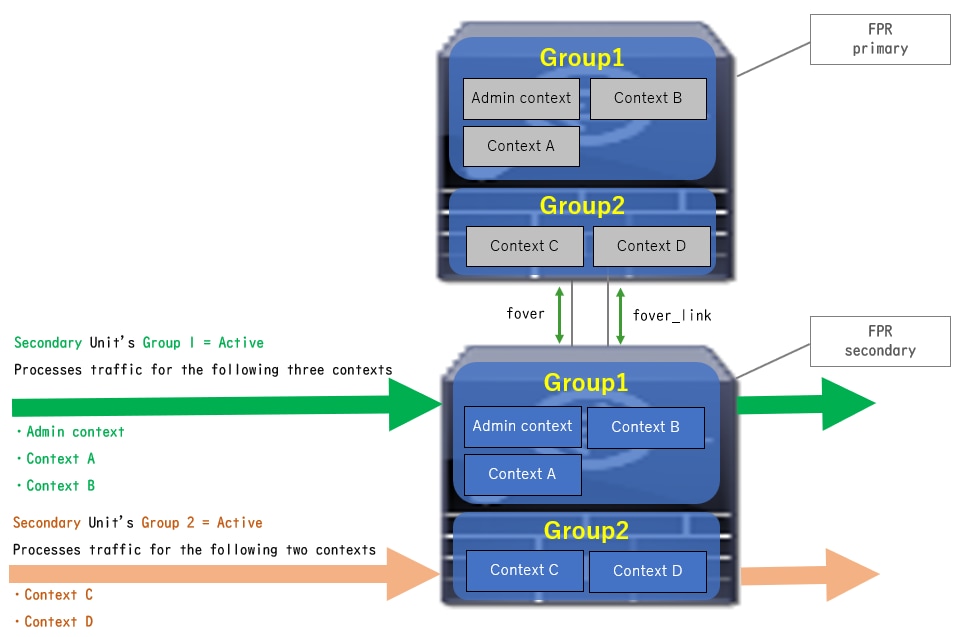
主用/主用故障轉移是自適應安全裝置(ASA)的一項功能,它允許兩個Firepower裝置同時傳遞流量。此配置通常用於負載平衡方案,在該方案中,您希望將流量拆分到兩個裝置之間以最大限度地提高吞吐量。它還用於冗餘目的,因此如果一個ASA發生故障,另一個可以接管而不會導致服務中斷。
ASA主用/主用故障切換機制
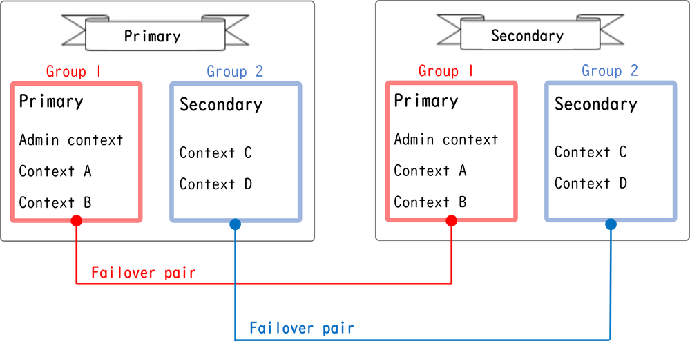
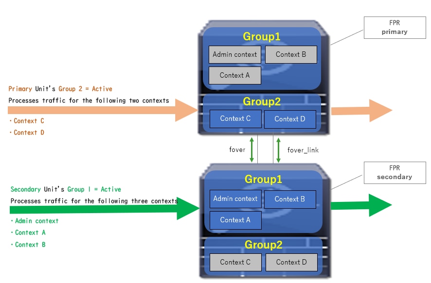
主用/主用故障轉移中的每個情景都手動分配給乙太網組1或組2。預設情況下將管理情景分配給組1。兩個機箱(單元)中的同一組(組1或組2)形成故障轉移對,從而實現冗餘功能。每個故障轉移對的行為與主用/備用故障轉移中的行為基本相同。有關主用/備用故障切換的詳細資訊,請參閱配置主用/備用故障切換。在主用/主用故障切換中,除了每個機箱的角色(主或輔助)外,每個組還具有角色(主或輔助)。 這些角色由使用者手動預設定,用於決定每個故障切換組的高可用性(HA)狀態(活動或備用)。
管理情景是處理基本機箱管理(如SSH)連線的特殊情景。這是主用/主用故障切換的映像。
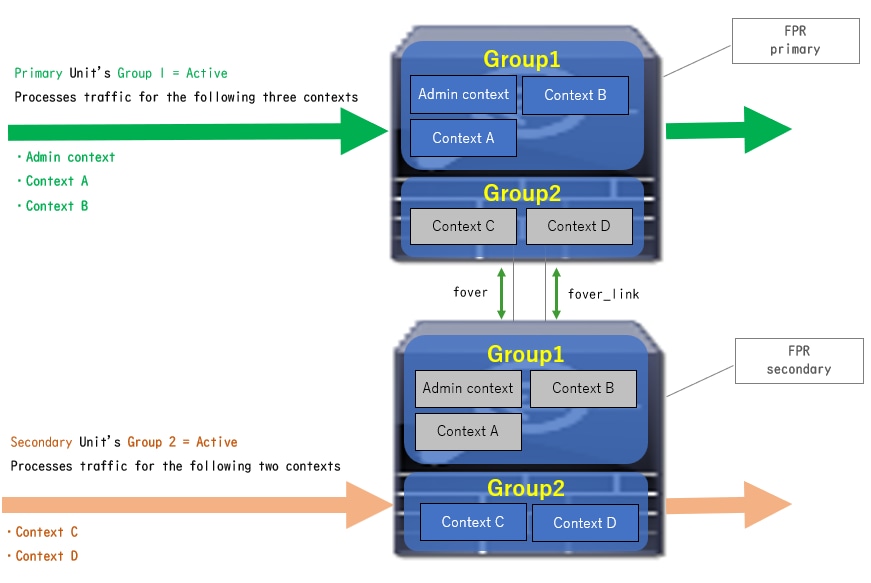
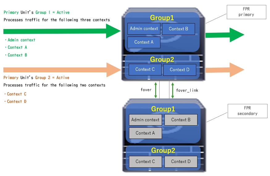
 主用/主用故障轉移中的故障轉移對
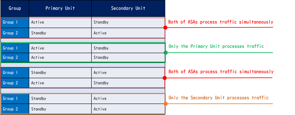
流量條件4
- 主裝置:組1 =備用,組2 =備用
- 輔助裝置:組1 =活動,組2 =活動
 流量條件4
流量條件4
主用/備用選擇規則
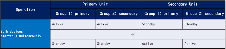
在主用/主用故障切換中,每個組的狀態(主用/備用)由以下規則確定:
- 假定2個裝置幾乎同時啟動,則其中一個裝置(主裝置或輔助裝置)將首先變為活動狀態。
- 經過搶佔時間後,在機箱和組中具有相同角色的組將變為活動狀態。
- 發生故障切換事件(如介面關閉)時,組的狀態更改的方式與主用/備用故障切換相同。
- 執行手動故障切換後,搶佔時間無法工作。
以下是狀態變更的範例。
- 兩台裝置幾乎同時啟動。狀態A →
- 搶佔時間已過。狀態B →
- 主裝置故障(觸發故障切換)。 狀態C →
- 自主裝置從故障中恢復以來經過的搶佔時間。狀態D →
- 手動觸發故障轉移。狀態E
有關故障轉移觸發器和運行狀況監控的詳細資訊,請參閱故障轉移事件。
1.兩台裝置幾乎同時啟動。
 狀態A
狀態A
2.超過搶佔時間(本文檔中為30秒)。
 狀態B
狀態B
3.主裝置的組1發生故障(如介面故障)。
 狀態C
狀態C
4.從主裝置組1從故障中恢復後經過的搶佔時間(本文檔中為30秒)。
 狀態D
狀態D
5.將「主裝置」的組2人工設定為「活動」。
 狀態E
狀態E
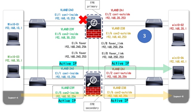
網路圖表
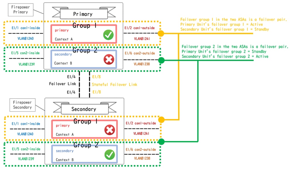
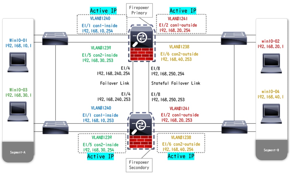
本文檔介紹基於此圖的主用/主用故障切換的配置和驗證。
 邏輯配置圖
邏輯配置圖
 物理配置圖
物理配置圖
組態
步驟1.預配置介面
對於Firepower和Firepower,請登入FCM GUI。導覽至Logical Devices > Edit。如圖所示,向ASA新增資料介面。
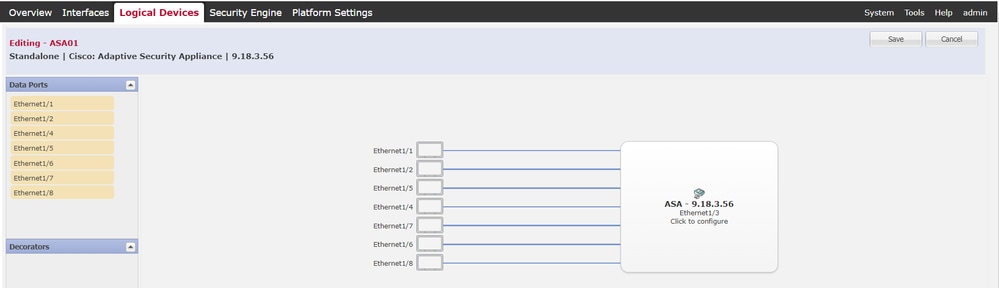 預配置介面
預配置介面
步驟2.主裝置上的配置
通過SSH或控制檯連線到主FXOS CLI。運行 connect module 1 console並 connect asa命令以進入ASA CLI。
a.在主裝置上配置故障切換(在主裝置的系統上下文中運行命令)。
failover lan unit primary
failover lan interface fover E1/4
failover link fover_link E1/8
failover interface ip fover 192.168.240.254 255.255.255.0 standby 192.168.240.253
failover interface ip fover_link 192.168.250.254 255.255.255.0 standby 192.168.250.253
failover group 1   <--- group 1 is assigned to primary by default
preempt 30
failover group 2
secondary
preempt 30
failover
prompt hostname state priority context
b.配置上下文的故障切換組(在主裝置的系統上下文中運行命令)。
admin-context admin
context admin         <--- admin context is assigned to group 1 by default
allocate-interface E1/3
config-url disk0:/admin.cfg

context con1
allocate-interface E1/1
allocate-interface E1/2
config-url disk0:/con1.cfg
join-failover-group 1 <--- add con1 context to group 1
!
context con2
allocate-interface E1/5
allocate-interface E1/6
config-url disk0:/con2.cfg
join-failover-group 2 <--- add con2 context to group 2
c.運行 changeto context con1,從系統上下文連線con1上下文。為con1上下文的介面配置IP(在主裝置的con1上下文中運行命令)。
interface E1/1
nameif con1-inside
ip address 192.168.10.254 255.255.255.0 standby 192.168.10.253
security-level 100
no shutdown
interface E1/2
nameif con1-outside
ip address 192.168.20.254 255.255.255.0 standby 192.168.20.253
no shutdown
d.運行 changeto context con2,從系統上下文連線con2上下文。為con2上下文的介面配置IP(在主裝置的con2上下文中運行命令)。
interface E1/5
nameif con2-inside
ip address 192.168.30.254 255.255.255.0 standby 192.168.30.253
security-level 100
no shutdown
interface E1/6
nameif con2-outside
ip address 192.168.40.254 255.255.255.0 standby 192.168.40.253
no shutdown
步驟3.在輔助裝置上配置
a.通過SSH或控制檯連線到輔助FXOS CLI。在輔助裝置上配置故障切換(在輔助裝置的系統上下文中運行命令)。
failover lan unit secondary
failover lan interface fover E1/4
failover link fover_link E1/8
failover interface ip fover 192.168.240.254 255.255.255.0 standby 192.168.240.253
failover interface ip fover_link 192.168.250.254 255.255.255.0 standby 192.168.250.253
b.運行命令 failover(在輔助裝置的系統上下文中運行)。
failover
步驟4.成功完成同步後確認故障切換狀態
a.在輔助裝置的系統上下文中運行show failover。
asa# show failover
Failover On
Failover unit Secondary
Failover LAN Interface: fover Ethernet1/4 (up)
Version: Ours 9.18(3)56, Mate 9.18(3)56
Serial Number: Ours FCH23157YFY, Mate FCH23037U8R
Group 1 last failover at: 17:00:56 JST Jan 11 2024
Group 2 last failover at: 17:00:56 JST Jan 11 2024

This host: Secondary    <--- group 1 and group 2 are Standby status in Secondary Unit
Group 1 State: Standby Ready
Active time: 0 (sec)
Group 2 State: Standby Ready
Active time: 945 (sec)

con1 Interface con1-inside (192.168.10.253): Unknown (Waiting)
con1 Interface con1-outside (192.168.20.253): Unknown (Waiting)
con2 Interface con2-inside (192.168.30.253): Unknown (Waiting)
con2 Interface con2-outside (192.168.40.253): Normal (Waiting)

Other host: Primary    <--- group 1 and group 2 are Active status in Primary Unit
Group 1 State: Active
Active time: 1637 (sec)
Group 2 State: Active
Active time: 93 (sec)

con1 Interface con1-inside (192.168.10.254): Normal (Monitored)
con1 Interface con1-outside (192.168.20.254): Normal (Monitored)
con2 Interface con2-inside (192.168.30.254): Normal (Waiting)
con2 Interface con2-outside (192.168.40.254): Normal (Waiting)

Stateful Failover Logical Update Statistics
Link : fover_link Ethernet1/8 (up)
b.(可選)運行 no failover active group 2命令將主裝置的組2手動切換為備用狀態(在主裝置的系統上下文中運行)。 這樣可以平衡通過防火牆的流量負載。
no failover active group 2

附註:如果運行此命令,則故障切換狀態與流量條件1匹配。
驗證
當E1/1關閉時,會觸發組1的故障切換,備用端(輔助裝置)上的資料介面將接管原始主用介面的IP和MAC地址,從而確保ASA持續傳遞流量(本文檔中的FTP連線)。
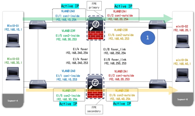 鏈路關閉之前
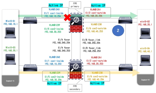 鏈路關閉期間
 已觸發故障轉移
步驟1.啟動從Win10-01到Win10-02的FTP連線
步驟2.故障轉移前確認FTP連線
運行 changeto context con1,從系統上下文連線con1上下文。確認在兩個ASA裝置中均建立了FTP連線。
asa/act/pri/con1# show conn
5 in use, 11 most used

! --- Confirm the connection in Primary Unit
TCP con1-outside 192.168.20.1:21 con1-inside 192.168.10.1:49703, idle 0:00:11, bytes 528, flags UIO

asa/stby/sec/con1# show conn
5 in use, 11 most used

! --- Confirm the connection in Secondary Unit
TCP con1-outside 192.168.20.1:21 con1-inside 192.168.10.1:49703, idle 0:00:14, bytes 528, flags UIO
步驟3.主裝置的E1/1鏈路斷開
步驟4.確認故障切換狀態
在系統上下文中,確認故障切換發生在組1中。
asa/act/sec# show failover
Failover On
Failover unit Secondary
Failover LAN Interface: fover Ethernet1/4 (up)
......
Group 1 last failover at: 20:00:16 JST Jan 11 2024
Group 2 last failover at: 17:02:33 JST Jan 11 2024

This host: Secondary
Group 1 State: Active  <--- group 1 of Secondary Unit is Switching to Active
Active time: 5 (sec)
Group 2 State: Active
Active time: 10663 (sec)

con1 Interface con1-inside (192.168.10.254): Normal (Waiting)
con1 Interface con1-outside (192.168.20.254): Normal (Waiting)
con2 Interface con2-inside (192.168.30.254): Normal (Monitored)
con2 Interface con2-outside (192.168.40.254): Normal (Monitored)

Other host: Primary
Group 1 State: Failed  <--- group 1 of Primary Unit is Switching to Failed status
Active time: 434 (sec)
Group 2 State: Standby Ready
Active time: 117 (sec)

con1 Interface con1-inside (192.168.10.253): Failed (Waiting)
con1 Interface con1-outside (192.168.20.253): Normal (Waiting)
con2 Interface con2-inside (192.168.30.253): Normal (Monitored)
con2 Interface con2-outside (192.168.40.253): Normal (Monitored)
步驟5.故障轉移後確認FTP連線
運行 changeto context con1,從系統情景連線con1情景,確認FTP連線未中斷。
asa/act/sec# changeto context con1
asa/act/sec/con1# show conn
11 in use, 11 most used

! --- Confirm the target FTP connection exists in group 1 of the Secondary Unit
TCP con1-outside 192.168.20.1:21 con1-inside 192.168.10.1:49703, idle 0:00:09, bytes 529, flags UIO
步驟6.確認搶佔時間的行為
主裝置的LinkUP E1/1並等待30秒(搶佔時間),故障切換狀態返回到原始狀態(匹配模式1中的通訊流)。
asa/stby/pri#
Group 1 preempt mate    <--- Failover is triggered automatically, after the preempt time has passed

asa/act/pri# show failover
Failover On
Failover unit Primary
Failover LAN Interface: fover Ethernet1/4 (up)
......
Group 1 last failover at: 11:02:33 UTC Jan 11 2024
Group 2 last failover at: 08:02:45 UTC Jan 11 2024

This host: Primary
Group 1 State: Active  <--- group 1 of Primary Unit is switching to Active status
Active time: 34 (sec)
Group 2 State: Standby Ready
Active time: 117 (sec)

con1 Interface con1-inside (192.168.10.254): Normal (Monitored)
con1 Interface con1-outside (192.168.20.254): Normal (Monitored)
con2 Interface con2-inside (192.168.30.253): Normal (Monitored)
con2 Interface con2-outside (192.168.40.253): Normal (Monitored)

Other host: Secondary
Group 1 State: Standby Ready  <---- group 1 of Secondary Unit is switching to Standby status
Active time: 125 (sec)
Group 2 State: Active
Active time: 10816 (sec)

con1 Interface con1-inside (192.168.10.253): Normal (Monitored)
con1 Interface con1-outside (192.168.20.253): Normal (Monitored)
con2 Interface con2-inside (192.168.30.254): Normal (Monitored)
con2 Interface con2-outside (192.168.40.254): Normal (Monitored)
虛擬MAC地址
在主用/主用故障切換中,始終使用虛擬MAC地址(手動設定值、自動生成的值或預設值)。活動虛擬MAC地址與活動介面關聯。
手動設定虛擬MAC地址
為了手動設定實體介面的虛擬MAC位址,可以使用 mac address命令或 mac-address命令(在I/F設定模式下)。以下是手動為實體介面E1/1設定虛擬MAC位址的範例。
asa/act/pri(config)# failover group 1
asa/act/pri(config-fover-group)# mac address E1/1 1234.1234.0001 1234.1234.0002

asa/act/pri(config-fover-group)# changeto context con1
asa/act/pri/con1(config)# show interface E1/1 | in MAC
MAC address 1234.1234.0001, MTU 1500 <--- Checking virtual MAC on the Primary Unit(con1) side

asa/stby/sec# changeto context con1
asa/stby/sec/con1# show interface E1/1 | in MAC
MAC address 1234.1234.0002, MTU 1500 <--- Checking virtual MAC on the Secondary Unit(con1) side
或
asa/act/pri(config)# changeto context con1
asa/act/pri/con1(config)# int E1/1
asa/act/pri/con1(config-if)# mac-addr 1234.1234.0001 standby 1234.1234.0002

asa/act/pri/con1(config)# show interface E1/1 | in MAC
MAC address 1234.1234.0001, MTU 1500 <--- Checking virtual MAC on the Primary Unit(con1) side

asa/stby/sec# changeto context con1
asa/stby/sec/con1# show interface E1/1 | in MAC
MAC address 1234.1234.0002, MTU 1500<--- Checking virtual MAC on the Secondary Unit(con1) side
自動設定虛擬MAC地址
還支援自動生成虛擬MAC地址。這可以通過使用命令來實現 mac-address auto 。虛擬MAC地址的格式為A2 xx.yyzz.zzzz,它正在自動生成。
A2:固定值
xx.yy :由命令選項中指定的<prefix prefix>生成(字首轉換為十六進位制,然後按反向順序插入)。
zz.zzzz :由內部計數器生成
以下是有關透過指令為介面產生虛擬 mac-address autoMAC位址的範例。
asa/act/pri(config)# mac-address auto
INFO: Converted to mac-address auto prefix 31

asa/act/pri(config)# show run all context con1 <--- Checking the virtual MAC addresses generated on con1 context
allocate-interface Ethernet1/1
mac-address auto Ethernet1/1 a21f.0000.0008 a21f.0000.0009
allocate-interface Ethernet1/2
mac-address auto Ethernet1/2 a21f.0000.000a a21f.0000.000b
config-url disk0:/con1.cfg
join-failover-group 1

asa/act/pri(config)# show run all context con2 <--- Checking the virtual MAC addresses generated on con2 context
context con2
allocate-interface Ethernet1/5
mac-address auto Ethernet1/5 a21f.0000.000c a21f.0000.000d
allocate-interface Ethernet1/6
mac-address auto Ethernet1/6 a21f.0000.000e a21f.0000.000f
config-url disk0:/con2.cfg
join-failover-group 2
虛擬MAC地址的預設設定
如果既沒有自動也沒有手動生成虛擬MAC地址,則使用預設虛擬MAC地址。
有關預設虛擬MAC地址的詳細資訊,請參閱《Cisco安全防火牆ASA系列命令參考指南》中的Command Default of mac address。
升級
您可以使用CLI或ASDM實現主用/主用故障切換對零停機時間升級。如需詳細資訊,請參閱升級作用中/作用中容錯移轉對。

 意見
意見