詳細設計手冊和使用EVPN VPWS、IOS XR版本 — 7.5.x的SR-TE顯式路徑策略的配置示例
下載選項
無偏見用語
本產品的文件集力求使用無偏見用語。針對本文件集的目的,無偏見係定義為未根據年齡、身心障礙、性別、種族身分、民族身分、性別傾向、社會經濟地位及交織性表示歧視的用語。由於本產品軟體使用者介面中硬式編碼的語言、根據 RFP 文件使用的語言,或引用第三方產品的語言,因此本文件中可能會出現例外狀況。深入瞭解思科如何使用包容性用語。
關於此翻譯
思科已使用電腦和人工技術翻譯本文件,讓全世界的使用者能夠以自己的語言理解支援內容。請注意,即使是最佳機器翻譯,也不如專業譯者翻譯的內容準確。Cisco Systems, Inc. 對這些翻譯的準確度概不負責,並建議一律查看原始英文文件(提供連結)。
目錄
簡介
本檔案介紹根據XYZ網路要求提供的詳細設計手冊(包括技術說明),並提供分段路由流量工程(SR-TE)明確路徑原則與乙太網路VPN(EVPN)虛擬私人有線服務(VPWS)的使用案例的低級組態模板和組態。
一、背景情況
1.1.超出範圍
本文檔不涵蓋使用XTC控制器、EVPN ELAN等集中式「按需」SR-TE策略的要求,但僅重點介紹具有EVPN VPWS覆蓋的頭端節點驅動的SR-TE策略。
1.2.假設
本文檔的讀者必須熟悉IP/MPLS和乙太網的概念以及分段路由和流量工程技術。
1.3.技術範圍
本文檔的主要技術範圍限於:
- 採用TI-LFA FRR的OSPF
- 頭端(分散式)控制的SR-TE策略
- 顯式主路徑和基於IGP的動態故障轉移路徑
- 單宿主EVPN VPWS
本文檔中提供的配置模板稱為Cisco IOS®-XR 7.5.x。
1.4.檔案摘要
表 1.文檔節
| 主題型別 |
主題名稱 |
章節編號 |
| 簡介 |
背景資訊 |
1 |
| 需求 |
使用者要求 |
2 |
| 技術概觀 |
分段路由 |
3 |
| SR-TE概述 |
4 |
|
| TI-LFA FRR |
5 |
|
| EVPN重疊 |
6 |
|
| BoB和負載平衡 |
7 |
|
| 組態範本 |
完整的設計解決方案 |
8 |
| 示例配置和Show命令 |
9 |
需求
2.使用者要求
2.1.要求摘要
服務提供商XYZ Networks要求通過Cisco NCS 5500裝置構建綠色現場網路。
其目的是將組播資料流(語音、影片)作為服務傳輸至具有特定要求的第2層傳輸網路,其中之一就是流量工程設計通過該網路的流量路徑。
他們首選使用傳輸標籤的SR、流量工程的SR-TE以及作為覆蓋層的EVPN來提供服務標籤。
2.2.採用元件
使用者XYZ已在NCS 5500路由器和線卡上收斂:
表2.專案硬體要求
| PE節點 |
PID |
| 機箱 |
NCS-5504 |
| 連線P節點的MPA/LC |
NC55-36X100G-A-SE |
| 連線CE節點的MPA/LC |
NC55-36X100G-A-SE |
| P節點 |
PID |
| 機箱 |
NCS-5508 |
| 連線其他P節點的MPA/LC |
NC55-36X100G-A-SE |
| 連線PE節點的MPA/LC |
NC55-36X100G-A-SE |
本部分概述了將使用的技術,並作簡要說明。
技術概觀
3.分段路由
3.1.什麼是分段路由?
分段路由是最新的高級MPLS技術,它正在通過引入標籤分發和流量工程(在一個傘下)來取代傳統的LDP和RSVP-TE協定,並且僅通過鏈路狀態IGP/BGP協定來實現它。
分段路由是一種根據源路由模式在網路上轉發資料包的方法。來源會選擇路徑,並將其編碼到封包標頭中,作為有序的區段清單。段是任何型別指令的識別符號。例如,拓撲段標識通向目的地的下一跳。每個資料段由資料段ID(SID)標識,資料段ID由一個平面無符號的20位整陣列成。
3.2.資料段識別符號
圖1.SR節點SID和鄰接SID

網段:內部網關協定(IGP)分配兩種型別的網段:字首網段和鄰接網段。每個路由器(節點)和每個鏈路(鄰接)都有一個關聯的分段識別符號(SID)。
字首SID:字首段是全域性段,因此字首SID在段路由域內全域性唯一,如圖1所示。字首SID與IP字首關聯。字首SID是從段路由全域性塊(SRGB)標籤範圍內手動配置的,由IS-IS或OSPF分發。首碼段將流量沿最短路徑引導至其目的地。
- 使用SR全域性塊(SRGB)
- SRGB通告的路由器功能TLV — 在配置中,字首SID可以配置為絕對值或索引
- 在協定通告中,Prefix-SID始終被編碼為全域性唯一索引。索引表示從SRGB基數偏移的零基編號,即0是第一個索引。例如,索引1對SID為16,000 + 1 = 16,001
節點SID:節點SID是標識特定節點的特殊型別的字首SID。它在環回介面下配置,以節點的環回地址作為字首。字首段是全域性段,因此字首SID在段路由域內是全域性唯一的。
換句話說,節點段是與標識節點的主機字首相關聯的字首段。
- 等效於router-id字首,即標識節點的字首
- Node-SID是在通告中設定了N-flag的字首SID
- 預設情況下,每個配置的Prefix-SID都是節點SID
- 「regular」(即非節點SID)Prefix-SID可為IS-IS配置
鄰接SID:鄰接段由稱為鄰接SID的標籤標識,該標籤表示到相鄰路由器的特定鄰接(如出口介面)。鄰接SID由IS-IS或OSPF分配。鄰接段將流量引導至特定鄰接。鄰接網段是本地網段,因此鄰接關係SID相對於特定路由器在本地是唯一的。
- 具有本地意義
- 自動為每個鄰接分配
- 始終編碼為絕對(即未索引)值
繫結SID或BSID:它是與SR策略關聯的本地重要SID。它有助於將封包導向其關聯的SR原則。 繫結段是標識SR-TE策略的本地段。每個SR-TE策略與繫結段ID(BSID)相關聯。
BSID是一個本地標籤,在例項化SR-TE策略時,會自動為每個SR-TE策略分配該標籤。 BSID可用於引導流量進入SR-TE策略並跨越域邊界,從而建立無縫的端到端域間SR-TE策略。
4. SR-TE概述
4.1.什麼是SR-TE?
分段路由流量工程(SR-TE)將SR的簡單、無狀態來源路由機制轉換到高級級別,對資料流量進行程式設計並通過預定義路徑引導資料流量,以避免擁塞,並提供備用路徑,就像快速通道即時流量圖一樣。
這是通過管理性配置通過多種約束組合定義的策略來實現的,這些約束對從源節點到目標節點的主路徑以及備份路徑進行程式設計。控制器可以是集中式(SDN)或分散式(頭端),這取決於網路需求。
讓我們考慮圖2中顯示的拓撲。假設連結的成本為預設值,且從A到達D的最短路徑為A-B-C-D,但低延遲路徑為A-E-F-G-H-D。操作員可以根據需要定義流量工程路徑(例如,延遲),並以段ID清單(A、E、F、G、H、D)的形式表示。與RSVP-TE不同,此策略的狀態只在路由器A上維護,而不是資料包經過的整個路由器(即E、F、G和H)。
圖2.SR-TE管理性定義路徑範例

4.2. SR-TE策略
流量工程分段路由(SR-TE)使用「策略」引導流量通過網路。SR-TE策略路徑表示為指定路徑的資料段清單,稱為資料段ID(SID)清單。每個網段都是從源到目的地的端到端路徑,指示網路中的路由器遵循指定路徑,而不是遵循IGP計算得出的最短路徑。如果將資料包引導到SR-TE策略中,則頭端會將SID清單推送到該資料包。網路的其餘部分執行嵌入在SID清單中的指令。
SR-TE策略被標識為有序清單(頭端、顏色、端點):
- 頭端 — SR-TE策略例項化的位置
- 顏色 — 區分兩個或多個策略到相同節點對(頭端 — 終端)的數值
- 終端 — SR-TE策略的目標
- 每個SR-TE策略都有一個顏色值。同一節點對之間的每個策略都需要唯一的顏色值。
SR-TE策略配置有一個或多個候選路徑,這些候選路徑包括主路徑和備份路徑。
例如,可以使用鄰接SID顯式定義策略的主路徑,在出現故障的情況下,備份路徑可以是IGP度量所照顧的動態路徑。
5. TI-LFA FRR
5.1.概述
拓撲無關無環替代(TI-LFA)是一種保護鏈路、節點和SRLG的功能。配置簡單;只需兩行配置即可將簡單的TI-LFA配置實施到路由器中。它不要求對路由器中使用的現有協定進行任何更改。圖3.顯示了本地鏈路故障和節點故障場景中TI-LFA的主要流量路徑和預先計算的備份路徑。
圖3.TI LFA鏈路故障轉移方案
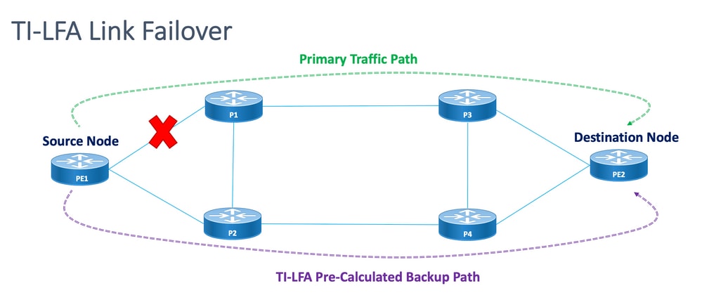
圖4.TI LFA節點故障轉移方案
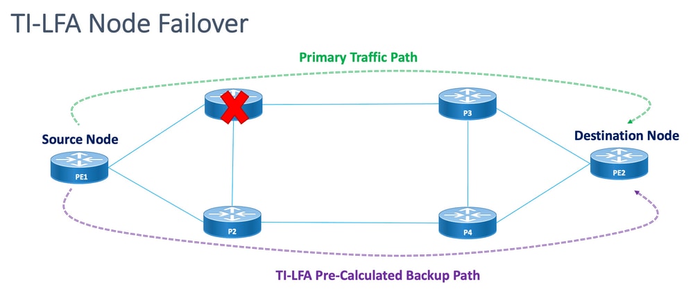
每個受保護的節點和路徑都有一個可以快速啟用的預計算備份路徑。受保護路徑的收斂時間為50毫秒或更短。這意味著,即使延遲或資料包丟失最敏感的應用程式在節點或鏈路出現故障時也不會出現中斷。TI-LFA計算備份路徑並暫時從資料庫中刪除受保護的連結或節點。接著,會先計算具有最短路徑的備份路徑。這可確保備份路徑具有儘可能低的度量成本,同時避免使用受保護的路徑。如果發生故障,會使用備份路徑之後的流量設計隧道。修復標籤清單確定需要新路由到達其目的地的資料包的路徑。修復標籤清單是正常的標籤堆疊,但僅在受保護路由發生故障時使用此清單。
5.2.故障檢測方法對故障恢復率的影響
針對SR-TE流量設計的路徑的快速重新路由被配置為在可行情況下在接近50毫秒內從主路徑到備份路徑的故障轉移情況下切換流量的一種方式。快速重新路由功能是在IGP(OSPF/ISIS)協定下配置的。收斂時間取決於進行鏈路故障檢測的方法。在光纖切割的情況下,檢測是立即的,且收斂速度小於50毫秒的可能性很高。但是,如果鏈路故障檢測必須由BFD執行,間隔為15毫秒(乘數x3)。收斂時間大部分超過50毫秒。
5.3.使用SR避免微環路
微環路是拓撲更改(鏈路關閉、鏈路開啟或度量更改事件)之後網路中出現的短暫資料包環路。微環路是由網路中不同節點的非同時收斂引起的。如果節點收斂並向尚未收斂的鄰居節點傳送流量,流量可能會在這兩個節點之間環路,從而導致資料包丟失、抖動和資料包順序混亂。
分段路由微環路迴避功能可檢測微環路後面是否可能存在拓撲更改。如果節點計算新拓撲上可能會出現微環路,則該節點會使用段清單建立通往目標的無環路SR-TE策略路徑。RIB更新延遲計時器到期後,SR-TE策略將替換為常規轉發路徑。RIB更新延遲有一個預設計時器,由TI-LFA處理。
6. EVPN重疊
EVPN是一項最初為乙太網多點服務設計的技術,具有先進的多宿主功能,使用BGP通過MPLS網路分發MAC地址可達性資訊,同時它為L2VPN帶來了IP VPN的相同操作和規模特性。如今,除了DCI和E-LAN應用之外,EVPN解決方案系列為所有乙太網服務型別(包括E-LINE和E-TREE)以及資料中心路由和橋接方案提供了通用基礎。EVPN還提供了在同一例項中組合第2層和第3層服務的選項。
EVPN是下一代解決方案,它通過MPLS網路提供乙太網多點服務。EVPN的運作與虛擬私人LAN服務(VPLS)相反,現有的虛擬私人LAN服務在核心層啟用BGP控制平面型MAC學習。在EVPN中,參與EVPN例項的PE使用MP-BGP協定在控制平面中學習使用者MAC路由。
EVPN帶來如前所述的許多好處:
- 按流冗餘和負載平衡
- 簡化的調配和操作
- 最佳轉發
- 快速收斂
- MAC地址可擴充性
- IETF標準化下的多供應商解決方案
需要在VLAN中的另一台裝置上學習或分配一台裝置上學習的MAC地址。EVPN軟體MAC學習功能可將一台裝置上學習的MAC地址分配給連線到網路的其它裝置。使用BGP從遠端裝置獲取MAC地址。
在這些部分中,您將瞭解EVPN的一些一般優勢和路由型別,然後瞭解應用於XYZ網路服務設計的特定於解決方案的元件。
6.1. EVPN優勢
L2VPN和L3VPN不僅藉助各種路由型別在一個解決方案保護傘下提供服務,EVPN還解決了服務提供商網路中乙太網服務的兩個長期限制:
- 多宿主和全主動乙太網路存取
- 服務提供商網路 — 與中心辦公室或資料中心整合
6.1.1.多宿主和全活動乙太網接入
該圖顯示了傳統的L2多點解決方案(如VPLS)的最大侷限性。
圖5.EVPN全主動存取
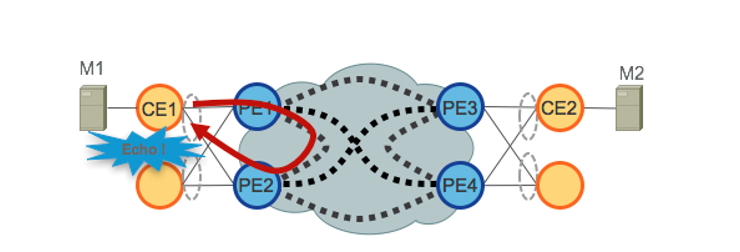
當VPLS在核心中運行時,環路避免要求PE1/PE2和PE3/PE4僅為其各自的CE提供單活動冗餘。傳統上,使用mLACP或傳統L2協定(如MST、REP、G.8032等)來提供單活動訪問冗餘。
分層式VPLS(H-VPLS)也存在相同的情況,其中接入節點負責通過主用和備用分支偽線(PW)提供單主用H-VPLS接入。
由於VPLS技術無法防止從核心中使用的某些流量類別的轉發機制派生的L2環路,因此無法部署全主動訪問冗餘模型。源自CE的廣播、未知單播和組播(BUM)流量在整個VPLS核心中泛洪,並由所有PE接收,然後泛洪到所有連線的CE。在我們的示例中,PE1可以將BUM流量從CE1泛洪到核心,並且PE2可以在收到流量後將其傳送回CE1。
EVPN使用基於BGP的控制平面技術來解決此問題,並為乙太網或H-EVPN接入啟用主動 — 主動訪問冗餘模型。
6.2. EVPN路由型別
EVPN定義了一個新的BGP NLRI,用於承載所有EVPN路由。EVPN NLRI在BGP中使用多重通訊協定擴充模組,AFI為25(L2VPN),SAFI為70。BGP功能通告用於確保兩個揚聲器支援EVPN NLRI。
圖6.EVPN NLRI
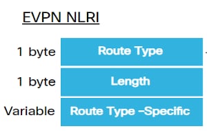
此實施所需的相關EVPN路由型別如下所述:
6.2.1.路由型別1 — 乙太網自動發現(AD)路由
根據EVI和每個ESI通告乙太網自動發現(AD)路由。這些路由是按ES傳送的。它們帶有屬於ES的EVI清單。當CE為單宿主時,ESI欄位設定為零。此路由型別用於大量MAC地址退出、負載平衡的別名以及水準分割過濾。
6.2.2.路由型別4 — 乙太網段路由
乙太網段路由使CE裝置能夠連線到兩個或PE裝置。通過ES路由可以發現連線到同一乙太網段的已連線PE裝置,即冗餘組發現。 它也用於指定轉發器(DF)選擇。
6.3. EVPN主機連線
支援以下EVPN模式:
- 單歸屬 — 這使您可以將使用者邊緣(CE)裝置連線到一個提供商邊緣(PE)裝置。在此,每個PE-CE連結的ESI值為空。
- 多宿主 — 這使您可以將一個使用者邊緣(CE)裝置連線到兩個或多個提供商邊緣(PE)裝置,以提供冗餘連線。不需要機箱間鏈路。冗餘PE裝置可確保發生網路故障時無流量中斷。多宿主的型別包括:
圖7.EVPN單歸航
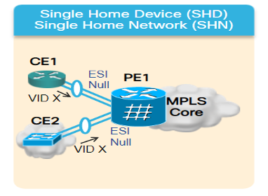
多宿主 — 以下是多宿主的型別:
1. Single-Active — 在單活動模式中,只有連線到特定乙太網段的一組PE中的一個PE允許向該乙太網段轉發和從該乙太網段轉發流量。
圖8.EVPN單主用
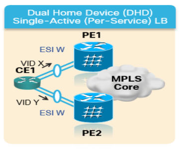
2.活動 — 活動 — 在活動 — 活動模式下,允許連線到特定乙太網段的所有PE將流量轉發到該乙太網段或從該乙太網段轉發流量。
圖9.EVPN雙主動
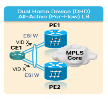
7. BoB和負載平衡
7.1.捆綁包上的BFD(BoB)
雙向轉發檢測(BFD)提供對相鄰轉發引擎之間路徑中故障的低開銷短持續時間檢測。BFD允許使用單一機制在任何介質和協定層進行故障檢測,檢測時間和開銷範圍很廣。在鏈路或鄰居出現故障時,快速檢測故障可立即對故障做出反應。
這會觸發IGP開始將流量轉送到已使用FRR(對於IGP)和PIC(對於BGP)計算的備份路徑。
在BFD Over套件組合(BoB)功能中,IPv4 BFD作業階段會在每個作用中套件組合成員上執行。
圖10BoB邏輯圖
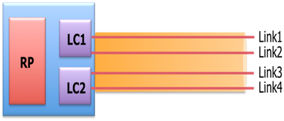
除了現有的L1/L2狀態之外,Bundlemgr還考慮BFD狀態以確定成員鏈路可用性。束成員狀態是以下項的函式:
L1狀態(物理鏈路)
L2狀態(LACP)
L3狀態(BFD)
BFD代理仍線上卡上運行。捆綁成員鏈路的BFD狀態在RP上合併。成員鏈路必須背對背連線,且兩者之間不能有任何L2交換機。BoB功能在整個XYZ網路的所有捆綁包乙太網介面中配置。
7.2.負載均衡
相關網路中的每個流量ECMP負載平衡跨套件組合間乙太網路介面和套件組合內乙太網路(位於套件組合介面的實體成員之間)。如前所述,這適用於從PE到PE(核心負載平衡)以及PE到CE(AC負載平衡)的整個網路。
7.2.1.使用FAT標籤實現核心負載均衡
根據XYZ網路的範圍,您必須只考慮每個流的ECMP(等價多重路徑)負載均衡,如前所述:
路由器通常根據標籤堆疊中最低的標籤(對於給定偽線上的所有流,該標籤是相同的標籤)對流量進行負載均衡。這可能導致非對稱負載均衡。在此上下文中,流是指具有相同源和目標對的資料包序列。從源提供商邊緣(PE)向目的地提供商邊緣PE傳輸分組。
流量感知傳輸偽線(FAT PW)提供識別偽線內個別流量的功能,並為路由器提供使用這些流量來負載均衡流量的功能。當使用等價多重路徑(ECMP)時,FAT PW用於平衡核心中的流量。基於不可分資料包流建立流標籤,該資料包流進入偽線,並作為資料包中最低的標籤插入。路由器可以使用流標籤進行負載均衡,這樣可以跨ECMP路徑或核心中的鏈路捆綁路徑提供更好的流量分佈。
將向堆疊新增一個額外的標籤,稱為流標籤,該標籤為PE上的每個唯一傳入流生成。流標籤是區分PW內流的唯一識別符號,它源自源MAC地址和目標MAC地址以及源和目標IP地址。流標籤包含標籤堆疊(EOS)位集的結尾。流標籤插入在VC標籤之後和控制字之前(如果有)。輸入PE計算並轉發流標籤。FAT PW配置啟用流標籤。出口PE丟棄流標籤,因此不會做出任何決定。
7.2.2.附件電路負載均衡
但是,對於AC捆綁成員的負載平衡,由於此網路部分沒有SR-MPLS,您需要一種不同的方法。
當明確調整所有PE路由器上的特定l2vpn配置旋鈕時,可以實現此處的按流負載均衡。根據要求,可以是每個SRC/DST MAC或SRC/DST IP。
組態範本 和命令示例
8.完整的設計解決方案
本節將討論由前面章節中介紹的所有不同單個元件拼接的完整設計詳細資訊。本節介紹參照Cisco IOS-XR 7.5.x的拓撲和相關配置模板。
8.1.低層次要求
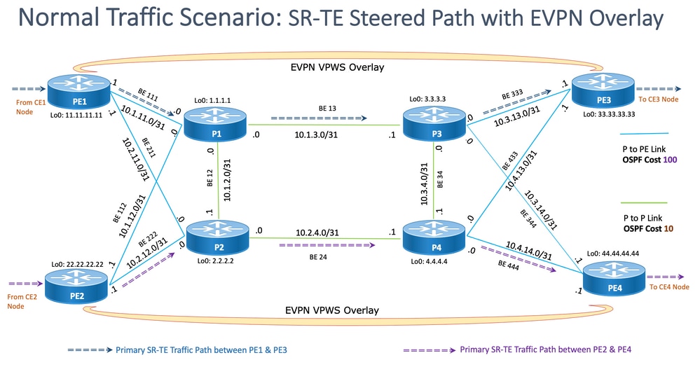
對於正常流量情況,流量設計為僅在PE1和PE3的服務終止之間以及PE2和PE4之間傳播。這種情形的主要目標是使流量路徑完全脫節,如圖12所示。
此處的相關流量將通過EVPN重疊封裝組播流。CE1節點和CE2節點分別產生組播媒體流(語音/影片),在PE1節點和PE2節點進行封裝,在PE3節點和PE4節點分別解封裝後通過EVPN L2覆蓋分別傳輸到CE3和CE4節點。
因此,除非另有說明,否則在所有情況下,源 — 目標流量對都視為PE1-PE3和PE2-PE4。有關要求詳細資訊,請參閱2.2小節。
8.2.設計概要
為了滿足這些要求,XYZ網路會根據需要選擇OSPF作為底層IGP。為了引導封裝的組播流穿過源 — 目標流量對通過所需路徑,必須在PE節點之間實施SR-TE。
SR-TE策略已設計為顯式路徑和動態IGP路徑。
顯式路徑包括:
- 正常流量案例
- 備用路徑選項可用之前的故障轉移方案
動態IGP路徑包括:
- 備用路徑選項不可用的故障切換備份路徑方案
BFD、TI-LFA和Microloop Avoidance等功能在OSPF下配置,如配置模板子部分所示。
對於正常流量方案,配置模板和其他詳細資訊將在小節8.5.1中介紹。
對於流量故障轉移方案,配置模板和其他詳細資訊將在子節8.5.2中介紹。
除此之外,還需要考慮在發生故障的情況下進行微環路避免和低於50毫秒的收斂時間。
8.3.設計模組
此小節捕獲所有設計塊,這些塊隨後在這些小節中詳細討論。
常規設計概述(第1層):
- 整個XYZ網路的MTU大小固定為「9216」,目標是支援最多5到6個SR標籤堆疊
- 「BFD over Bundle」是以15毫秒的間隔實施,以檢測50毫秒以下的光纖切割
OSPF/SR-TE設計概述:
- 作為IGP協定的OSPF,TI-LFA配置為提供50毫秒以下收斂時間的FRR
- 基於作為轉發平面的段路由和作為路由協議的OSPF的傳輸層
- 在XYZ網路中,分段路由流量工程顯式路徑會引導所有所需主路徑方向的流量。在鏈路/節點故障切換情況下,流量通過動態igp路徑路由
- 微環路避免和OSPF最大度量也是此設計的一部分
BGP/RR設計概述:
- 一個群集中配置了兩個RR以提供冗余
- 每個PE中的XYZ網路、BGP過程分別形成「IPv4」和「L2VPN EVPN」與兩個RR對等
服務設計概述:
- 服務層構建在基於BGP的控制平面和第2層點對點EVPN(EVPN-VPWS)之上
- 多點傳送視訊(UDP)流量透過點對點EVPN-VPWS PW進行封裝
- ECMP負載平衡通過配置EVPN部分下的FAT標籤來實現
- 該服務旨在支援最多5到6個SR標籤堆疊,其中包括SR傳輸標籤、EVPN標籤和用於負載平衡的FAT標籤
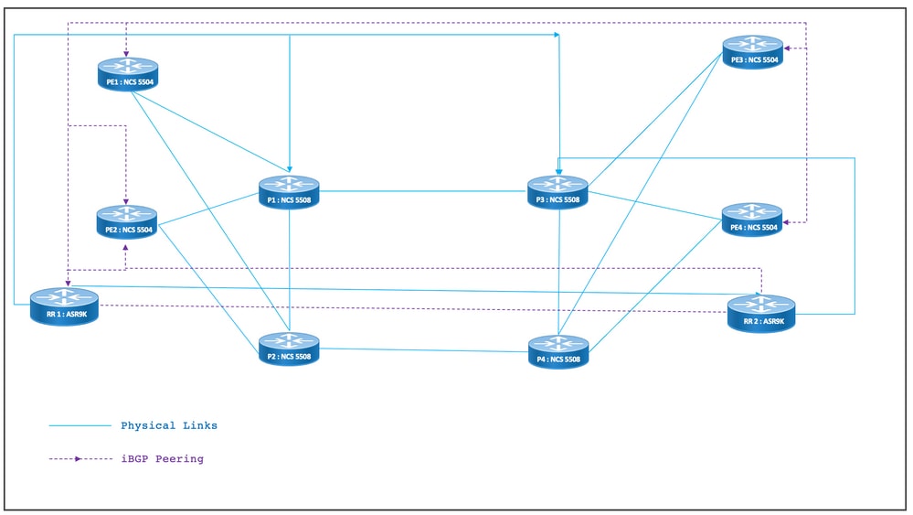
8.4.物理拓撲示例
XYZ網路的物理拓撲如圖所示。為簡單起見,僅顯示4個PE和4個P節點。有兩個RR節點在集群中運行以提供冗餘。
圖11物理拓撲
8.5.第1層設計詳細資訊
在通用第1層設計中,有一個捆綁包乙太網,每個捆綁包至少配置兩個成員鏈路。要快速檢測鏈路故障,請選擇BFD而不是套件組合功能。時間間隔理想地可在5-15毫秒之間變化。這取決於解除安裝的硬體功能。
有關BFD的詳細資訊,請參閱https://www.cisco.com/c/en/us/td/docs/iosxr/ncs5500/routing/73x/b-routing-cg-ncs5500-73x/implementing-bfd.html。 請注意,此功能僅需在捆綁包乙太網介面下配置,無需在IGP下配置。MTU大小固定在9216,旨在支援最多5到6個SR標籤堆疊。
8.5.1.配置模板
所有節點的BFD over Bundle配置模板如下所示:
interface Bundle-Ether <Intf-Number>

 bfd address-family ipv4 timers start 60

 bfd address-family ipv4 timers nbr-unconfig 60

 bfd address-family ipv4 multiplier 3

 bfd address-family ipv4 destination <Connected-Intf-IP>

 bfd address-family ipv4 fast-detect

 bfd address-family ipv4 minimum-interval <Time in msec>

 mtu <Value as per requirement>

 ipv4 address <Intf IP> <Subnet Mask>>

 bundle minimum-active links 1

!
8.6. OSPF/SR-TE設計概述
網路中的所有OSPFv2路由器都位於區域0中,因此網路處理單個IGP域。
在路由器OSPF下,分段路由已啟用,並且已配置相關的捆綁包乙太網介面。同樣,在Bundle Interfaces下,啟用網路型別和快速重新路由引數。最重要的是,在配置了Prefix-SID的被動模式下啟用環回介面。
OSPF是鏈路狀態協定,因此,必須優先立即識別下行鏈路,並且需要建立備份路徑。為此,在套件組合介面下配置套件組合上的BFD和OSPF下的TI-LFA FRR,這樣在光纖切斷情況下會保持收斂時間為50毫秒。
以下各小節詳細描述了流量路徑的正常和故障轉移方案:
8.6.1. SR-TE正常流量案例
為了維護非常嚴格的主路徑,SR-TE策略設計為使用前面提到的源 — 目標流量對之間的端到端顯式路徑。此外,一個SR-TE策略內需要多個首選候選路徑,以便為多個故障切換方案提供調配。
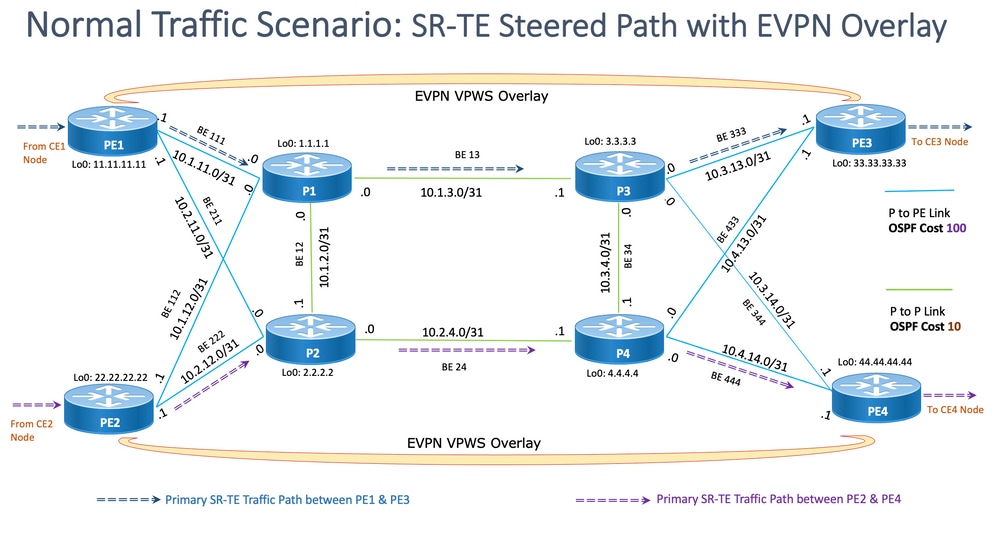
此圖顯示了使用者網路詳細資訊,這些詳細資訊與8.3子部分中提到的設計塊一致。
- PE到P和P到P節點之間的鏈路
- 所有節點的環回地址
- 所有節點的介面地址
- SR-TE導向的正常流量路徑方向
- PE節點之間的EVPN重疊
未故意顯示RR以減少拓撲中的雜亂。
PE和P之間的鏈路標有藍色,P和P之間的鏈路標有綠色。PE到P鏈路的OSPF開銷為100,而P到P鏈路的開銷為10。
主SR-TE流量流在PE1-PE3對之間標有藍色箭頭,在PE2-PE4對之間標有紫色箭頭。
圖 12.拓撲詳細資訊
8.6.1.1.配置模板
此子部分包含用於PE1和PE2節點的OSPF/SR-TE的相關配置模板,如下所示:
# PE1 Node: OSPF & SR-TE configs
router ospf CORE
nsr
distribute link-state Command to distribute OSPF database into SR-TE database
log adjacency changes
router-id <Router-ID-PE1> OSPF Router-ID
segment-routing mpls
nsf cisco
microloop avoidance segment-routing Command to enable microloop avoidance with TI-LFA
area 0
interface Bundle-Ether<Intf-Number> OSPF PE to P Link
cost 100 OSPF PE to P Metric
authentication keychain <Key-Chain> Command to enable OSPF Authentication per link
network point-to-point
fast-reroute per-prefix Commands to enable TI-LFA
fast-reroute per-prefix ti-lfa enable
fast-reroute per-prefix tiebreaker node-protecting index <Index-Value>
prefix-suppression
!
interface Loopback <Loopback-ID-PE1>
passive enable
prefix-sid index <SID-Index-Number1> OSPF Loopback Prefix SID
注意:要全域性配置Source-Address"命令,或者在POLICY下配置。作為預設行為,策略下的源地址將取代全域性命令。
在特定場景中需要分段路由配置下的source address命令,如圖所示,在這些特定場景中,在同一PE中,作為SR-TE策略的源,我們需要在多個地址中選擇一個環回地址,或者當ISIS和OSPF使用單獨的環回運行時,我們需要凍結其中一個環回地址。否則,在正常情況下,如果只有一個IGP使用唯一環回運行,則源地址配置是可選的。
segment-routing
global-block 16000 23999 Default SRGB Value (Need not be configured). Needs to be configured only if non-default value is assigned
local-block 15000 15999 Default SRLB Value (Need not be configured). Needs to be configured only if non-default value is assigned
traffic-eng
candidate-paths
all
source-address ipv4Configure SR-TE source address as OSPF loopback (Global Option)
!
!
segment-list name <SIDLIST1> Primary/Normal Path SID-LIST1
index <Index ID> mpls adjacency <Remote-IP-Address-Link1>
index <Index ID> mpls adjacency <Remote-IP-Address-Link2>
index <Index ID> mpls adjacency <Remote-IP-Address-Link3>
!
segment-list name <SIDLIST2> Primary Back Up Path SID-LIST2
index <Index ID> mpls adjacency <Remote-IP-Address-Link4>
index <Index ID> mpls adjacency <Remote-IP-Address-Link5>
index <Index ID> mpls adjacency <Remote-IP-Address-Link6>
!
segment-list name <SIDLIST3> Secondary Back Up Path SID-LIST3
index <Index ID> mpls adjacency <Remote-IP-Address-Link4>
index <Index ID> mpls adjacency <Remote-IP-Address-Link5>
index <Index ID> mpls adjacency <Remote-IP-Address-Link6>
!
policy <Pol-Name1>
source-address ipv4 Configure SR-TE source address as OSPF loopback (Policy Specific Option)
color <Color-ID> end-point ipv4 <Destn-PE3>
candidate-paths
preference 50 Tertiary Back Up Path with least preference
dynamic
metric
type igp
!
!
!
preference 100 Secondary Back Up Path with 3rd highest preference
explicit segment-list <SIDLIST3>
!
!
preference 150 Primary Back Up Path with 2nd highest preference
explicit segment-list <SIDLIST2>
!
!
preference 200 Primary/Normal Path with highest preference (Active Path for PE1 in this scenario)
explicit segment-list <SIDLIST1>
!
!
!
!
!
!
# PE2 Node: OSPF & SR-TE configs
router ospf CORE
nsr
distribute link-state Command to distribute OSPF database into SR-TE database
log adjacency changes
router-id <Router-ID-PE2> OSPF Router-ID
segment-routing mpls
nsf cisco
microloop avoidance segment-routing Command to enable microloop avoidance with TI-LFA
area 0
interface Bundle-Ether<Intf-Number> OSPF PE to P Link
cost 100 OSPF PE to P Metric
authentication keychain <Key-Chain> Command to enable OSPF Authentication per link
network point-to-point
fast-reroute per-prefix Commands to enable TI-LFA
fast-reroute per-prefix ti-lfa enable
fast-reroute per-prefix tiebreaker node-protecting index <Index-Value>
prefix-suppression
!
interface Loopback <Loopback-ID-PE2>
passive enable
prefix-sid index <SID-Index-Number2> OSPF Loopback Prefix SID
註:已刪除可選的源地址、預設SRGB和SRLB命令。
segment-routing
traffic-eng
!
!
segment-list name <SIDLIST1> Primary/Normal Path SID-LIST1
index <Index ID> mpls adjacency <Remote-IP-Address-Link1>
index <Index ID> mpls adjacency <Remote-IP-Address-Link2>
index <Index ID> mpls adjacency <Remote-IP-Address-Link3>
!
segment-list name <SIDLIST2> Primary Back Up Path SID-LIST2
index <Index ID> mpls adjacency <Remote-IP-Address-Link4>
index <Index ID> mpls adjacency <Remote-IP-Address-Link5>
index <Index ID> mpls adjacency <Remote-IP-Address-Link6>
!
segment-list name <SIDLIST3> Secondary Back Up Path SID-LIST3
index <Index ID> mpls adjacency <Remote-IP-Address-Link4>
index <Index ID> mpls adjacency <Remote-IP-Address-Link5>
index <Index ID> mpls adjacency <Remote-IP-Address-Link6>
!
policy <Pol-Name1>
source-address ipv4 Configure SR-TE source address as OSPF loopback (Policy Specific Option)
color <Color-ID> end-point ipv4 <Destn-PE4>
candidate-paths
preference 50 Tertiary Back Up Path with least preference
dynamic
metric
type igp
!
!
!
preference 100 Secondary Back Up Path with 3rd highest preference
explicit segment-list <SIDLIST3>
!
!
preference 150 Primary Back Up Path with 2nd highest preference
explicit segment-list <SIDLIST2>
!
!
preference 200 Primary/Normal Path with highest preference (Active Path for PE2 in this scenario)
explicit segment-list <SIDLIST1>
!
!
!
!
!
!
註意:在上述解決方案中,網段清單的明確跳基於IP地址,因為正如此處所述,基於「mpls label」的明確路徑SR-TE策略配置路徑驗證在7.3.x中無法用於遠端鏈路故障
如果除PE節點的本地鏈路以外的任何遠端鏈路出現故障,則路徑仍然有效。這是設計好的,在XR 7.5.x之前無法修改
# PE Node: SR-TE configs


router ospf <Process-Name>

 address-family ipv4 unicast

 area 0

  interface <Core BE Intf1>

  adjacency-sid absolute <Adj-SID1>

  interface <Core BE Intf2>

  adjacency-sid absolute < Adj-SID2>

  interface <Core BE Intf3>

  adjacency-sid absolute < Adj-SID3>


segment-routing

 traffic-eng

  policy <Pol-Name1>

   color <Color-ID> end-point ipv4 <Destn-PE>

   candidate-paths

    preference 10

     explicit segment-list <SIDLIST1>

     !

    preference 20

     dynamic

       metric

       type igp

     !

  segment-list name <SIDLIST1>

    index 10 mpls label <Adj-SID-Link1>

    index 20 mpls label <Adj-SID-Link2>

    index 30 mpls label <Adj-SID-Link3>
8.6.2.適用於故障轉移方案的SR-TE
要瞭解流量故障轉移場景,必須仔細檢視正常流量條件下主路徑流量,如上一小節中的拓撲圖中所述。
在故障轉移場景中,主要目的是在給定當前拓撲基礎結構的情況下,儘可能最大程度地保持流量路徑不連續。XYZ網路對管理性引導流量通過備份路徑中的特定節點有嚴格的要求,以便保持源 — 目標節點對之間的最大分離。此設計旨在避免已用鏈路過載,並儘量減少未使用的鏈路。
這些子部分顯示了各種故障切換場景,如單鏈路、雙鏈路、單節點和雙節點,以及流量用於保持最大不連續性的故障切換路徑。
8.6.3.單鏈路故障轉移方案
這是單鏈路故障場景,其中PE1和P1之間的本地鏈路發生故障,流量通過核心P2和P1節點繞行。這是通過segment-list <SIDLIST1>管理引導的,該清單形成PE1和PE3節點之間的主備份路徑
圖 13.單鏈路故障轉移方案
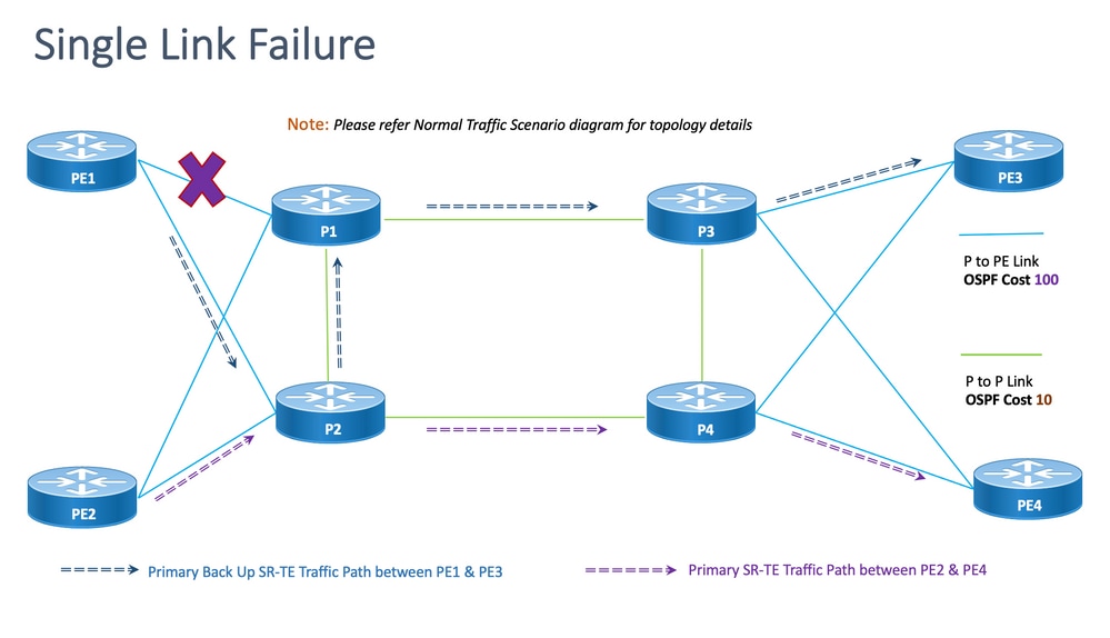
脫節:對於單鏈路故障,共用的公共鏈路數為零(0),如前面的拓撲所示。
8.6.3.1.配置模板
此子部分包含用於PE1和PE2節點的OSPF/SR-TE的相關配置模板,如下所示:
注意:路由器OSPF的PE1和PE2配置模板與正常場景類似。
# PE1 Node: OSPF & SR-TE configs
segment-routing
traffic-eng
!
!
segment-list name <SIDLIST1> Primary/Normal Path SID-LIST1
index <Index ID> mpls adjacency <Remote-IP-Address-Link1>
index <Index ID> mpls adjacency <Remote-IP-Address-Link2>
index <Index ID> mpls adjacency <Remote-IP-Address-Link3>
!
segment-list name <SIDLIST2> Primary Back Up Path SID-LIST2
index <Index ID> mpls adjacency <Remote-IP-Address-Link4>
index <Index ID> mpls adjacency <Remote-IP-Address-Link5>
index <Index ID> mpls adjacency <Remote-IP-Address-Link6>
!
segment-list name <SIDLIST3> Secondary Back Up Path SID-LIST3
index <Index ID> mpls adjacency <Remote-IP-Address-Link4>
index <Index ID> mpls adjacency <Remote-IP-Address-Link5>
index <Index ID> mpls adjacency <Remote-IP-Address-Link6>
!
policy <Pol-Name1>
source-address ipv4 Configure SR-TE source address as OSPF loopback (Policy Specific Option)
color <Color-ID> end-point ipv4 <Destn-PE3>
candidate-paths
preference 50 Tertiary Back Up Path with least preference
dynamic
metric
type igp
!
!
!
preference 100 Secondary Back Up Path with 3rd highest preference
explicit segment-list <SIDLIST3>
!
!
preference 150 Primary Back Up Path with 2nd highest preference (Active Path for PE1 in this scenario)
explicit segment-list <SIDLIST2>
!
!
preference 200 Primary/Normal Path with highest preference
explicit segment-list <SIDLIST1>
!
!
!
!
!
!
注意:路由器OSPF的PE1和PE2配置模板與正常場景類似。
# PE2 Node: OSPF & SR-TE configs
segment-routing
traffic-eng
!
!
segment-list name <SIDLIST1> Primary/Normal Path SID-LIST1
index <Index ID> mpls adjacency <Remote-IP-Address-Link1>
index <Index ID> mpls adjacency <Remote-IP-Address-Link2>
index <Index ID> mpls adjacency <Remote-IP-Address-Link3>
!
segment-list name <SIDLIST2> Primary Back Up Path SID-LIST2
index <Index ID> mpls adjacency <Remote-IP-Address-Link4>
index <Index ID> mpls adjacency <Remote-IP-Address-Link5>
index <Index ID> mpls adjacency <Remote-IP-Address-Link6>
!
segment-list name <SIDLIST3> Secondary Back Up Path SID-LIST3
index <Index ID> mpls adjacency <Remote-IP-Address-Link4>
index <Index ID> mpls adjacency <Remote-IP-Address-Link5>
index <Index ID> mpls adjacency <Remote-IP-Address-Link6>
!
policy <Pol-Name1>
source-address ipv4 Configure SR-TE source address as OSPF loopback (Policy Specific Option)
color <Color-ID> end-point ipv4 <Destn-PE4>
candidate-paths
preference 50 Tertiary Back Up Path with least preference
dynamic
metric
type igp
!
!
!
preference 100 Secondary Back Up Path with 3rd highest preference
explicit segment-list <SIDLIST3>
!
!
preference 150 Primary Back Up Path with 2nd highest preference
explicit segment-list <SIDLIST2>
!
!
preference 200 Primary/Normal Path with highest preference (Active Path for PE2 in this scenario)
explicit segment-list <SIDLIST1>
!
!
!
!
!
!
8.6.4.雙鏈路故障轉移方案
這是PE1和P1之間的本地鏈路以及PE2和P2之間的本地鏈路發生故障的雙鏈路故障情況。來自PE1的流量通過核心P2和P1節點繞行,來自PE2的流量通過核心P1和P2節點繞行。
它們分別通過PE1和PE2各自的分段清單<SIDLIST2>進行管理,這些分段清單分別構成PE1和PE3以及PE2和PE4節點之間的輔助備份路徑。
圖14雙鏈路故障切換場景
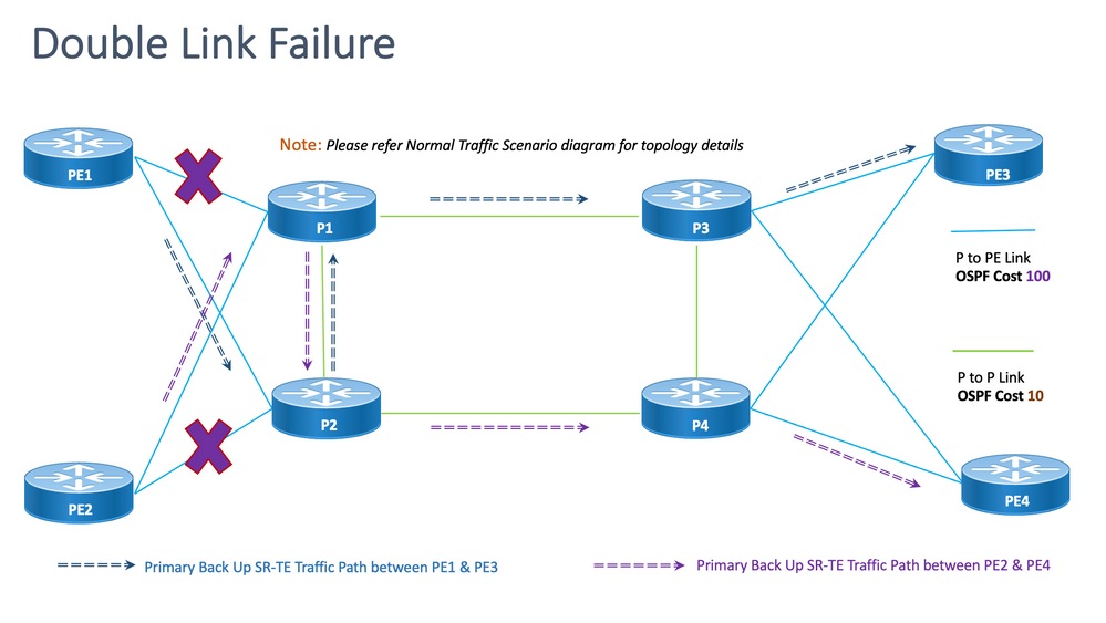
脫節:對於雙鏈路故障,共用的公共鏈路數為一(1),如上述拓撲所示。
8.6.4.1.配置模板
此子部分包含用於PE1和PE2節點的OSPF/SR-TE的相關配置模板,如下所示:
注意:路由器OSPF的PE1和PE2配置模板與正常場景類似。
# PE1 Node: OSPF & SR-TE configs

#show run router ospf


router ospf CORE

 distribute link-state

 log adjacency changes

 router-id 11.11.11.11

 segment-routing mpls

 microloop avoidance segment-routing

 area 0

  interface Bundle-Ether11

   cost 100

   authentication keychain XYZ-CONT-PE1

   network point-to-point

   fast-reroute per-prefix

   fast-reroute per-prefix ti-lfa enable

   fast-reroute per-prefix tiebreaker node-protecting index 200

   prefix-suppression

  !

  interface Bundle-Ether12

   cost 100

   authentication keychain XYZ-CONT-PE1

   network point-to-point

   fast-reroute per-prefix

   fast-reroute per-prefix ti-lfa enable

   fast-reroute per-prefix tiebreaker node-protecting index 200

   prefix-suppression

  !

  interface Loopback0

   passive enable

   prefix-sid index 11

  !

 !

!
segment-routing
traffic-eng
!
!
segment-list name <SIDLIST1> Primary/Normal Path SID-LIST1
index <Index ID> mpls adjacency <Remote-IP-Address-Link1>
index <Index ID> mpls adjacency <Remote-IP-Address-Link2>
index <Index ID> mpls adjacency <Remote-IP-Address-Link3>
!
segment-list name <SIDLIST2> Primary Back Up Path SID-LIST2
index <Index ID> mpls adjacency <Remote-IP-Address-Link4>
index <Index ID> mpls adjacency <Remote-IP-Address-Link5>
index <Index ID> mpls adjacency <Remote-IP-Address-Link6>
!
segment-list name <SIDLIST3> Secondary Back Up Path SID-LIST3
index <Index ID> mpls adjacency <Remote-IP-Address-Link4>
index <Index ID> mpls adjacency <Remote-IP-Address-Link5>
index <Index ID> mpls adjacency <Remote-IP-Address-Link6>
!
policy <Pol-Name1>
source-address ipv4 Configure SR-TE source address as OSPF loopback (Policy Specific Option)
color <Color-ID> end-point ipv4 <Destn-PE3>
candidate-paths
preference 50 Tertiary Back Up Path with least preference
dynamic
metric
type igp
!
!
!
preference 100 Secondary Back Up Path with 3rd highest preference
explicit segment-list <SIDLIST3>
!
!
preference 150 Primary Back Up Path with 2nd highest preference (Active Path for PE1 in this scenario)
explicit segment-list <SIDLIST2>
!
!
preference 200 Primary/Normal Path with highest preference
explicit segment-list <SIDLIST1>
!
!
!
!
!
!
注意:路由器OSPF的PE1和PE2配置模板與正常場景類似。
# PE2 Node: OSPF & SR-TE configs
segment-routing
traffic-eng
!
!
segment-list name <SIDLIST1> Primary/Normal Path SID-LIST1
index <Index ID> mpls adjacency <Remote-IP-Address-Link1>
index <Index ID> mpls adjacency <Remote-IP-Address-Link2>
index <Index ID> mpls adjacency <Remote-IP-Address-Link3>
!
segment-list name <SIDLIST2> Primary Back Up Path SID-LIST2
index <Index ID> mpls adjacency <Remote-IP-Address-Link4>
index <Index ID> mpls adjacency <Remote-IP-Address-Link5>
index <Index ID> mpls adjacency <Remote-IP-Address-Link6>
!
segment-list name <SIDLIST3> Secondary Back Up Path SID-LIST3
index <Index ID> mpls adjacency <Remote-IP-Address-Link4>
index <Index ID> mpls adjacency <Remote-IP-Address-Link5>
index <Index ID> mpls adjacency <Remote-IP-Address-Link6>
!
policy <Pol-Name1>
source-address ipv4 Configure SR-TE source address as OSPF loopback (Policy Specific Option)
color <Color-ID> end-point ipv4 <Destn-PE4>
candidate-paths
preference 50 Tertiary Back Up Path with least preference
dynamic
metric
type igp
!
!
!
preference 100 Secondary Back Up Path with 3rd highest preference
explicit segment-list <SIDLIST3>
!
!
preference 150 Primary Back Up Path with 2nd highest preference (Active Path for PE2 in this scenario)
explicit segment-list <SIDLIST2>
!
!
preference 200 Primary/Normal Path with highest preference
explicit segment-list <SIDLIST1>
!
!
!
!
!
!
8.6.5.單節點故障轉移方案
這是單節點故障場景,節點P1發生故障,流量通過核心P2和P4節點繞行。這是通過segment-list <SIDLIST3>管理引導的,該清單形成PE1和PE3節點之間的輔助備份路徑。
但是,PE2和PE4之間的流量仍然與主路徑相同,如本拓撲所示。
圖15單節點故障轉移方案
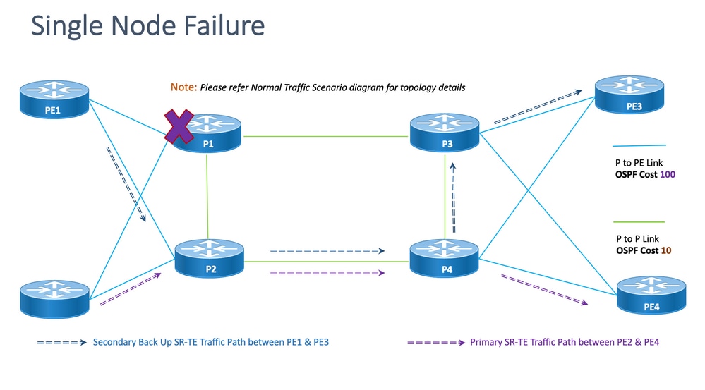
脫節:對於單節點故障,共用的公共鏈路數為一(1),如上述拓撲所示。
8.6.5.1.配置模板
此子部分包含用於PE1和PE2節點的OSPF/SR-TE的相關配置模板,如下所示:
注意:路由器OSPF的PE1和PE2配置模板與正常場景類似。
segment-routing
traffic-eng
!
!
segment-list name <SIDLIST1> Primary/Normal Path SID-LIST1
index <Index ID> mpls adjacency <Remote-IP-Address-Link1>
index <Index ID> mpls adjacency <Remote-IP-Address-Link2>
index <Index ID> mpls adjacency <Remote-IP-Address-Link3>
!
segment-list name <SIDLIST2> Primary Back Up Path SID-LIST2
index <Index ID> mpls adjacency <Remote-IP-Address-Link4>
index <Index ID> mpls adjacency <Remote-IP-Address-Link5>
index <Index ID> mpls adjacency <Remote-IP-Address-Link6>
!
segment-list name <SIDLIST3> Secondary Back Up Path SID-LIST3
index <Index ID> mpls adjacency <Remote-IP-Address-Link4>
index <Index ID> mpls adjacency <Remote-IP-Address-Link5>
index <Index ID> mpls adjacency <Remote-IP-Address-Link6>
!
policy <Pol-Name1>
source-address ipv4 Configure SR-TE source address as OSPF loopback (Policy Specific Option)
color <Color-ID> end-point ipv4 <Destn-PE3>
candidate-paths
preference 50 Tertiary Back Up Path with least preference
dynamic
metric
type igp
!
!
!
preference 100 Secondary Back Up Path with 3rd highest preference (Active Path for PE1 in this scenario)
explicit segment-list <SIDLIST3>
!
!
preference 150 Primary Back Up Path with 2nd highest preference
explicit segment-list <SIDLIST2>
!
!
preference 200 Primary/Normal Path with highest preference
explicit segment-list <SIDLIST1>
!
!
!
!
!
!
注意:路由器OSPF的PE1和PE2配置模板與正常場景類似。
# PE2 Node: OSPF & SR-TE configs
segment-routing
traffic-eng
!
!
segment-list name <SIDLIST1> Primary/Normal Path SID-LIST1
index <Index ID> mpls adjacency <Remote-IP-Address-Link1>
index <Index ID> mpls adjacency <Remote-IP-Address-Link2>
index <Index ID> mpls adjacency <Remote-IP-Address-Link3>
!
segment-list name <SIDLIST2> Primary Back Up Path SID-LIST2
index <Index ID> mpls adjacency <Remote-IP-Address-Link4>
index <Index ID> mpls adjacency <Remote-IP-Address-Link5>
index <Index ID> mpls adjacency <Remote-IP-Address-Link6>
!
segment-list name <SIDLIST3> Secondary Back Up Path SID-LIST3
index <Index ID> mpls adjacency <Remote-IP-Address-Link4>
index <Index ID> mpls adjacency <Remote-IP-Address-Link5>
index <Index ID> mpls adjacency <Remote-IP-Address-Link6>
!
policy <Pol-Name1>
source-address ipv4 Configure SR-TE source address as OSPF loopback (Policy Specific Option)
color <Color-ID> end-point ipv4 <Destn-PE4>
candidate-paths
preference 50 Tertiary Back Up Path with least preference
dynamic
metric
type igp
!
!
!
preference 100 Secondary Back Up Path with 3rd highest preference
explicit segment-list <SIDLIST3>
!
!
preference 150 Primary Back Up Path with 2nd highest preference
explicit segment-list <SIDLIST2>
!
!
preference 200 Primary/Normal Path with highest preference (Active Path for PE2 in this scenario)
explicit segment-list <SIDLIST1>
!
!
!
!
!
!
8.6.6.雙節點故障轉移方案
這是雙節點故障場景,節點P1和P3出現故障,流量通過核心P2和P4節點繞行。這是通過segment-list <SIDLIST3>管理引導的,該清單形成PE1和PE3節點之間的輔助備份路徑。由於顯式路徑僅針對前面提到的2種方案定義,因此,此處動態IGP路徑形成第三級備份路徑,並承擔通過P2和P4節點路由流量的角色。
但是,PE2和PE4之間的流量仍然與主路徑相同,如本拓撲所示。
圖16雙節點故障轉移方案。
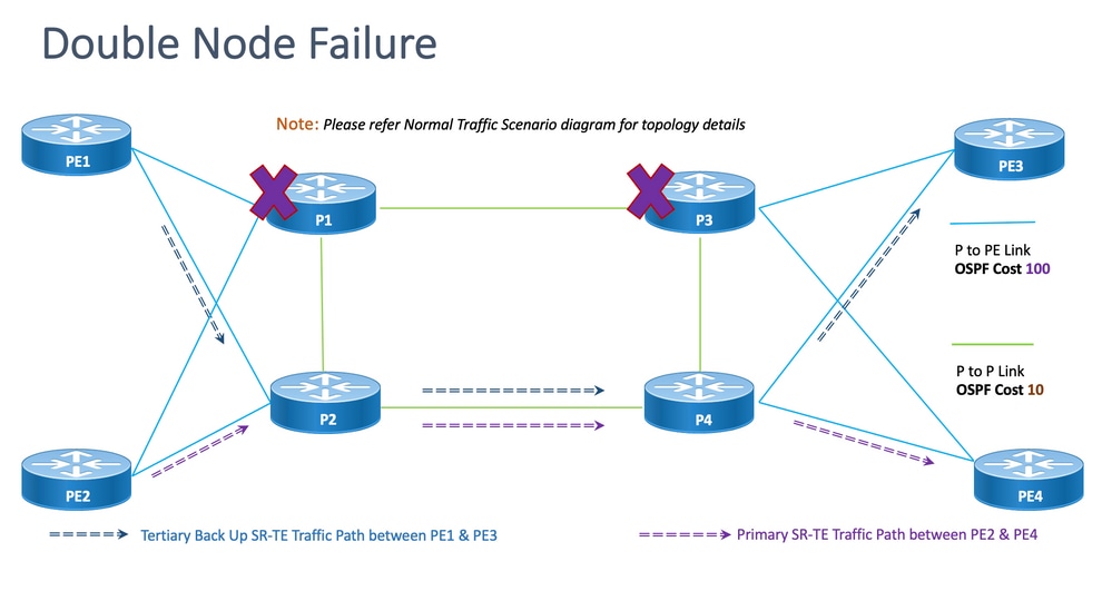
脫節:對於雙節點故障,共用的公共鏈路數為一(1),如本拓撲所示。
8.6.6.1.配置模板
此子部分包含用於PE1和PE2節點的OSPF/SR-TE的相關配置模板,如下所示:
注意:路由器OSPF的PE1和PE2配置模板與正常場景類似。
# PE1 Node: OSPF & SR-TE configs
segment-routing
traffic-eng
!
!
segment-list name <SIDLIST1> Primary/Normal Path SID-LIST1
index <Index ID> mpls adjacency <Remote-IP-Address-Link1>
index <Index ID> mpls adjacency <Remote-IP-Address-Link2>
index <Index ID> mpls adjacency <Remote-IP-Address-Link3>
!
segment-list name <SIDLIST2> Primary Back Up Path SID-LIST2
index <Index ID> mpls adjacency <Remote-IP-Address-Link4>
index <Index ID> mpls adjacency <Remote-IP-Address-Link5>
index <Index ID> mpls adjacency <Remote-IP-Address-Link6>
!
segment-list name <SIDLIST3> Secondary Back Up Path SID-LIST3
index <Index ID> mpls adjacency <Remote-IP-Address-Link4>
index <Index ID> mpls adjacency <Remote-IP-Address-Link5>
index <Index ID> mpls adjacency <Remote-IP-Address-Link6>
!
policy <Pol-Name1>
source-address ipv4 Configure SR-TE source address as OSPF loopback (Policy Specific Option)
color <Color-ID> end-point ipv4 <Destn-PE3>
candidate-paths
preference 50 Tertiary Back Up Path with least preference (Active Path for PE1 in this scenario -
Policy chooses Least Cost IGP Back Up Path in absence of Valid Explicit Path)
dynamic
metric
type igp
!
!
!
preference 100 Secondary Back Up Path with 3rd highest preference
explicit segment-list <SIDLIST3>
!
!
preference 150 Primary Back Up Path with 2nd highest preference
explicit segment-list <SIDLIST2>
!
!
preference 200 Primary/Normal Path with highest preference
explicit segment-list <SIDLIST1>
!
!
!
!
!
!
注意:路由器OSPF的PE1和PE2配置模板與正常場景類似。
# PE2 Node: OSPF & SR-TE configs
segment-routing
traffic-eng
!
!
segment-list name <SIDLIST1> Primary/Normal Path SID-LIST1
index <Index ID> mpls adjacency <Remote-IP-Address-Link1>
index <Index ID> mpls adjacency <Remote-IP-Address-Link2>
index <Index ID> mpls adjacency <Remote-IP-Address-Link3>
!
segment-list name <SIDLIST2> Primary Back Up Path SID-LIST2
index <Index ID> mpls adjacency <Remote-IP-Address-Link4>
index <Index ID> mpls adjacency <Remote-IP-Address-Link5>
index <Index ID> mpls adjacency <Remote-IP-Address-Link6>
!
segment-list name <SIDLIST3> Secondary Back Up Path SID-LIST3
index <Index ID> mpls adjacency <Remote-IP-Address-Link4>
index <Index ID> mpls adjacency <Remote-IP-Address-Link5>
index <Index ID> mpls adjacency <Remote-IP-Address-Link6>
!
policy <Pol-Name1>
source-address ipv4 Configure SR-TE source address as OSPF loopback (Policy Specific Option)
color <Color-ID> end-point ipv4 <Destn-PE4>
candidate-paths
preference 50 Tertiary Back Up Path with least preference
dynamic
metric
type igp
!
!
!
preference 100 Secondary Back Up Path with 3rd highest preference
explicit segment-list <SIDLIST3>
!
!
preference 150 Primary Back Up Path with 2nd highest preference
explicit segment-list <SIDLIST2>
!
!
preference 200 Primary/Normal Path with highest preference (Active Path for PE2 in this scenario)
explicit segment-list <SIDLIST1>
!
!
!
!
!
!
8.7. BGP/RR設計概述
邊界閘道通訊協定(BGP)是在Internet上作出核心路由決定的通訊協定。它維護一個IP網路或「字首」表,指定自治系統(AS)之間的網路可達性。它被描述為路徑向量協定。BGP不使用傳統的內部網關協定(IGP)度量,而是根據路徑、網路策略和/或規則集做出路由決策。因此,更適合將其稱為可達性協定,而不是路由協定。
MP-BGP可用於通過網路傳播IPv4、IPv6、VPNv4、VPNv6、EVPN和鏈路狀態字首。這通過路由反射器設定完成,該設定通過核心、聚合、接入裝置和SR-PCE裝置形成iBGP鄰居。
透過RR,BGP學習的字首透過iBGP在內部傳播。BGP路由絕不會重新分發到IGP中。路由反射器完全與資料平面隔離,專用於控制平面目的。
8.7.1.配置模板
此子節包含有關BGP/RR的相關配置模板,如下所示:
# PE Node: Relevant BGP configs
router bgp <PE-ASN>
address-family l2vpn evpn
!
neighbor-group <RR-EVPN> Neighbor group of Route Reflector (RR)
remote-as <RR-ASN>
update-source <PE-Self-Loopback>
!
address-family l2vpn evpn AF L2VPN EVPN Neighborship with RR
maximum-prefix <PREFIX> <PERCENT> warning-only
!
address-family ipv4 rt-filter
!
neighbor <RR1-Loopback> Neighborship with RR1 using the above neighbor group
use neighbor-group <RR-EVPN>
neighbor <RR2-Loopback> Neighborship with RR2 using the above neighbor group
use neighbor-group <RR-EVPN>
# RR Nodes: Relevant BGP configs
router bgp <RR-ASN>
address-family l2vpn evpn
!
neighbor-group <PE-EVPN> Neighbor group of Provider Edge (PE)
remote-as <PE-ASN>
update-source <RR-Self-Loopback>
!
address-family l2vpn evpn AF L2VPN EVPN Neighborship with PE
route-reflector-client
!
address-family ipv4 rt-filter
!
neighbor <PE1-Loopback> Neighborship with PE1 using the above neighbor group
use neighbor-group <PE-EVPN>
neighbor <PE2-Loopback> Neighborship with PE2 using the above neighbor group
use neighbor-group <PE-EVPN>
8.8.服務設計概述
此子部分介紹EVPN VPWS重疊服務,以及支援的標籤堆疊和配置模板的表示。
EVPN-VPWS是用於點對點服務的BGP控制平面解決方案。它實施在一對PE之間建立EVPN例項的信令和封裝技術。它能夠在沒有MAC查詢的情況下,將流量從一個網路轉發到另一個網路。將EVPN用於VPWS無需為點對點乙太網服務傳送單段和多段PW訊號。EVPN-VPWS技術工作在IP和MPLS核心上;IP核心支援BGP和MPLS核心在端點之間交換資料包。
8.8.1.標籤堆疊表示
該服務旨在支援最多5到6個SR標籤堆疊,包括SR傳輸標籤、EVPN標籤和用於負載平衡的FAT標籤。這是流量流經顯式主路徑的正常方案中分析的最大標籤數:
| ADJ SID1 |
|
| ADJ SID2 |
|
| ADJ SID3 |
|
| EVPN標籤 |
|
| 流標籤(S=1) |
這是故障切換方案中流量流經備份顯式路徑或IGP定義的動態備份路徑時分析的最大標籤數:
| TI-LFA SID1 |
| TI-LFA SID2 |
| TI-LFA SID3 |
| EVPN標籤 |
| 流標籤(S=1) |
8.8.2.配置模板
此小節包含EVPN-VPWS的相關配置模板,如下所示:
# PE Node: EVPN configs
evpn
evi <EVI-ID> Ethernet Virtual Identifier
bgp
rd <RD-Value>
route-target import <RT-Value>
route-target export <RT-Value>
!
load-balancing
flow-label static Generates bottom-most label (S=1) for load balancing between intra & inter BE end-to-end
!
!
interface <AC-Interface>
l2vpn
pw-class <PW-Class-Name1>
encapsulation mpls
preferred-path sr-te policy <Pol-Name1> Attaching SR-TE policy as the traffic path of EVPN
!
!
xconnect group <Group-Name>
p2p <P2P-Name>
interface <AC-Subinterface> EVPN Attachment Circuit Interface towards CE
neighbor evpn evi <EVI-ID> service <Service-ID> Service ID defined should match at both the end PEs
pw-class <PW-Class-Name1>
!
9.示例配置和Show命令
本最後部分僅包含普通流量場景下PE節點的相關配置和show命令。此處捕獲的引數與下圖中給出的引數一致,作為參考,這有助於理解前面部分中介紹的配置模板。
9.1. PE節點的示例配置
圖17包含配置引數的拓撲。
# PE1 Node: OSPF & SR-TE Config
#show run router ospf
router ospf CORE
distribute link-state Command to distribute OSPF database into SR-TE database
log adjacency changes
router-id 11.11.11.11 OSPF Router ID
segment-routing mpls
microloop avoidance segment-routing Command to enable microloop avoidance with TI-LFA
area 0
interface Bundle-Ether111 OSPF PE to P Link
cost 100 OSPF PE to P Metric
authentication keychain XYZ-CONT-PE1 Command to enable OSPF Authentication per link
network point-to-point
fast-reroute per-prefix Commands to enable TI-LFA
fast-reroute per-prefix ti-lfa enable
fast-reroute per-prefix tiebreaker node-protecting index 200
prefix-suppression
!
interface Bundle-Ether211
cost 100
authentication keychain XYZ-CONT-PE1
network point-to-point
fast-reroute per-prefix
fast-reroute per-prefix ti-lfa enable
fast-reroute per-prefix tiebreaker node-protecting index 200
prefix-suppression
!
interface Loopback0
passive enable
prefix-sid index 11 OSPF Loopback Prefix SID
!
!
!
#show run segment-routing
Sat Apr 16 23:22:42.727 UTC
segment-routing
traffic-eng
segment-list PrimaryPath Primary/Normal Path
index 10 mpls adjacency 10.1.11.0
index 20 mpls adjacency 10.1.3.1
index 30 mpls adjacency 10.3.13.1
!
segment-list PrimaryBackUpPath Primary Back Up Path
index 10 mpls adjacency 10.2.11.0
index 20 mpls adjacency 10.1.2.0
index 30 mpls adjacency 10.1.3.1
!
segment-list SecondaryBackUpPath Secondary Back Up Path
index 10 mpls adjacency 10.2.11.0
index 20 mpls adjacency 10.2.4.1
index 30 mpls adjacency 10.3.4.0
!
policy SR-TE_POLICY_PE1-to-PE3 SR-TE Policy Towards PE3
color 10 end-point ipv4 33.33.33.33 SR-TE Policy End-Point PE3 Loopback
candidate-paths
preference 50 Tertiary Back Up Dynamic IGP Path with 4th highest preference
dynamic
metric
type igp
!
!
!
preference 100 Secondary Back Up Path with 3rd highest preference
explicit segment-list SecondaryBackUpPath
!
!
preference 150 Primary Back Up Path with 2nd highest preference
explicit segment-list PrimaryBackUpPath
!
!
preference 200 Primary and Active Path with highest preference
explicit segment-list PrimaryPath
!
!
!
!
!
!
# PE2 Node: OSPF & SR-TE Config
#show run router ospf
router ospf CORE
distribute link-state Command to distribute OSPF database into SR-TE database
log adjacency changes
router-id 22.22.22.22 OSPF Router ID
segment-routing mpls
microloop avoidance segment-routing Command to enable microloop avoidance with TI-LFA
area 0
interface Bundle-Ether112 OSPF PE to P Link
cost 100 OSPF PE to P Metric
authentication keychain XYZ-CONT-PE2
network point-to-point
fast-reroute per-prefix Commands to enable TI-LFA
fast-reroute per-prefix ti-lfa enable
fast-reroute per-prefix tiebreaker node-protecting index 200
prefix-suppression
!
interface Bundle-Ether222
cost 100
authentication keychain XYZ-CONT-PE2 Command to enable OSPF Authentication per link
network point-to-point
fast-reroute per-prefix Commands to enable TI-LFA
fast-reroute per-prefix ti-lfa enable
fast-reroute per-prefix tiebreaker node-protecting index 200
prefix-suppression
!
interface Loopback0
passive enable
prefix-sid index 22 OSPF Loopback Prefix SID
!
!
!
#show run segment-routing
Sat Apr 16 23:22:42.727 UTC
segment-routing
traffic-eng
segment-list PrimaryPath Primary/Normal Path
index 10 mpls adjacency 10.2.12.0
index 20 mpls adjacency 10.2.4.1
index 30 mpls adjacency 10.4.14.1
!
segment-list PrimaryBackUpPath Primary Back Up Path
index 10 mpls adjacency 10.1.12.0
index 20 mpls adjacency 10.1.2.1
index 30 mpls adjacency 10.2.4.1
!
segment-list SecondaryBackUpPath Secondary Back Up Path
index 10 mpls adjacency 10.1.12.0
index 20 mpls adjacency 10.1.3.1
index 30 mpls adjacency 10.3.4.1
!
policy SR-TE_POLICY_PE2-to-PE4 SR-TE Policy Towards PE4
color 10 end-point ipv4 44.44.44.44 SR-TE Policy End-Point PE4 Loopback
candidate-paths
preference 50 Tertiary Back Up Dynamic IGP Path with 4th highest preference
dynamic
metric
type igp
!
!
!
preference 100 Secondary Back Up Path with 3rd highest preference
explicit segment-list SecondaryBackUpPath
!
!
preference 150 Primary Back Up Path with 2nd highest preference
explicit segment-list PrimaryBackUpPath
!
!
preference 200 Primary and Active Path with highest preference
explicit segment-list PrimaryPath
!
!
!
!
!
!
# PE1 Node: BGP Config
#show run router bgp
router bgp 64848
bgp router-id 11.11.11.11 BGP Router-ID
address-family l2vpn evpn
!
neighbor-group RR-EVPN
remote-as 64848
update-source Loopback0
address-family l2vpn evpn BGP AF L2VPN EVPN
!
!
neighbor 10.10.10.10 Neighbor Route Reflector
use neighbor-group RR-EVPN
!
!
# PE2 Node: BGP Config
#show run router bgp
router bgp 64848
bgp router-id 22.22.22.22 BGP Router-ID
address-family l2vpn evpn
!
neighbor-group RR-EVPN
remote-as 64848
update-source Loopback0
address-family l2vpn evpn BGP AF L2VPN EVPN
!
!
neighbor 10.10.10.10 Neighbor Route Reflector
use neighbor-group RR-EVPN
!
!
# PE1 Node: EVPN-VPWS Config
evpn
evi 100 Ethernet Virtual Identifier
bgp
rd 11:11
route-target import 100:100
route-target export 100:100
!
load-balancing Generates bottom-most label (S=1) for load balancing between intra & inter BE end-to-end
flow-label static
!
!
interface Bundle-Ether99 Interface Attachment Circuit
ethernet-segment
identifier type 0 00.00.00.00.00.00.00.00.00
!
!
!
# PE2 Node: EVPN-VPWS Config
evpn
evi 100 Ethernet Virtual Identifier
bgp
rd 11:11
route-target import 100:100
route-target export 100:100
!
load-balancing Generates bottom-most label (S=1) for load balancing between intra & inter BE end-to-end
flow-label static
!
!
interface Bundle-Ether99 Interface Attachment Circuit
ethernet-segment
identifier type 0 00.00.00.00.00.00.00.00.00
!
!
!
9.1. PE節點上的相關show命令
# PE1 Node: SR-TE Show Command
#show segment-routing traffic-eng policy
Sat Apr 16 23:35:32.731 UTC
SR-TE policy database
---------------------
Color: 10, End-point: 33.33.33.33
Name: srte_c_10_ep_33.33.33.33
Status:
Admin: up Operational: up for 00:12:54 (since Apr 16 23:22:38.278)
Candidate-paths:
Preference: 200 (configuration) (active) Active Path (Path in use)
Name: SR-TE_POLICY_PE1-to-PE3
Requested BSID: dynamic
Protection Type: protected-preferred
Maximum SID Depth: 12
Explicit: segment-list PrimaryPath (valid) Only the Active Path shows valid
Weight: 1, Metric Type: TE
24007 [Adjacency-SID, 10.1.11.0 - 10.1.11.1]
24007 [Adjacency-SID, 10.1.3.0 - 10.1.3.1]
24005 [Adjacency-SID, 10.3.13.0 - 10.3.13.1]
Preference: 150 (configuration)
Name: SR-TE_POLICY_PE1-to-PE3
Requested BSID: dynamic
Protection Type: protected-preferred
Maximum SID Depth: 12
Explicit: segment-list PrimaryBackUpPath (invalid) All inactive paths show invalid
Weight: 1, Metric Type: TE
Preference: 100 (configuration)
Name: SR-TE_POLICY_PE1-to-PE3
Requested BSID: dynamic
Protection Type: protected-preferred
Maximum SID Depth: 12
Explicit: segment-list SecondaryBackUpPath (invalid)
Weight: 1, Metric Type: TE
Preference: 50 (configuration) All inactive paths show invalid
Name: SR-TE_POLICY_PE1-to-PE3
Requested BSID: dynamic
Protection Type: protected-preferred
Maximum SID Depth: 12
Dynamic (invalid)
Metric Type: IGP, Path Accumulated Metric: 0
Attributes:
Binding SID: 24020
Forward Class: Not Configured
Steering labeled-services disabled: no
Steering BGP disabled: no
IPv6 caps enable: yes
Invalidation drop enabled: no
# PE2 Node: SR-TE Show Command
#show segment-routing traffic-eng policy
Sat Apr 16 23:35:32.731 UTC
SR-TE policy database
---------------------
Color: 10, End-point: 44.44.44.44
Name: srte_c_10_ep_44.44.44.44
Status:
Admin: up Operational: up for 00:12:54 (since Apr 16 23:22:38.278)
Candidate-paths:
Preference: 200 (configuration) (active) Active Path (Path in use)
Name: SR-TE_POLICY_PE1-to-PE3
Requested BSID: dynamic
Protection Type: protected-preferred
Maximum SID Depth: 12
Explicit: segment-list PrimaryPath (valid) Only the Active Path shows valid
Weight: 1, Metric Type: TE
24007 [Adjacency-SID, 10.2.12.0 - 10.2.12.1]
24007 [Adjacency-SID, 10.2.4.0 - 10.2.4.1]
24005 [Adjacency-SID, 10.4.14.0 - 10.4.14.1]
Preference: 150 (configuration)
Name: SR-TE_POLICY_PE1-to-PE3
Requested BSID: dynamic
Protection Type: protected-preferred
Maximum SID Depth: 12
Explicit: segment-list PrimaryBackUpPath (invalid) All inactive paths show invalid
Weight: 1, Metric Type: TE
Preference: 100 (configuration)
Name: SR-TE_POLICY_PE1-to-PE3
Requested BSID: dynamic
Protection Type: protected-preferred
Maximum SID Depth: 12
Explicit: segment-list SecondaryBackUpPath (invalid)
Weight: 1, Metric Type: TE
Preference: 50 (configuration) All inactive paths show invalid
Name: SR-TE_POLICY_PE1-to-PE3
Requested BSID: dynamic
Protection Type: protected-preferred
Maximum SID Depth: 12
Dynamic (invalid)
Metric Type: IGP, Path Accumulated Metric: 0
Attributes:
Binding SID: 24020
Forward Class: Not Configured
Steering labeled-services disabled: no
Steering BGP disabled: no
IPv6 caps enable: yes
Invalidation drop enabled: no
# PE1 Node: BGP Show Command


#show bgp l2vpn evpn summary

Sun Apr 17 07:16:23.574 UTC


Address Family: L2VPN EVPN

--------------------------


BGP router identifier 11.11.11.11, local AS number 64848

BGP generic scan interval 60 secs

Non-stop routing is enabled

BGP table state: Active

Table ID: 0x0   RD version: 0

BGP main routing table version 25

BGP NSR Initial initsync version 1 (Reached)

BGP NSR/ISSU Sync-Group versions 25/0

BGP scan interval 60 secs


BGP is operating in STANDALONE mode.


Process       RcvTblVer   bRIB/RIB   LabelVer  ImportVer  SendTblVer  StandbyVer

Speaker              25         25         25         25          25          25


Neighbor        Spk    AS MsgRcvd MsgSent   TblVer  InQ OutQ  Up/Down  St/PfxRcd

10.10.10.10      0  64848    9500    9484       25    0    0    5d16h          1


# PE2 Node: BGP Show Command


#show bgp l2vpn evpn summary

Sun Apr 17 07:16:23.574 UTC


Address Family: L2VPN EVPN

--------------------------


BGP router identifier 22.22.22.22, local AS number 64848

BGP generic scan interval 60 secs

Non-stop routing is enabled

BGP table state: Active

Table ID: 0x0   RD version: 0

BGP main routing table version 25

BGP NSR Initial initsync version 1 (Reached)

BGP NSR/ISSU Sync-Group versions 25/0

BGP scan interval 60 secs
BGP在獨立模式下運作。
Process       RcvTblVer   bRIB/RIB   LabelVer  ImportVer  SendTblVer  StandbyVer

Speaker              25         25         25         25          25          25


Neighbor        Spk    AS MsgRcvd MsgSent   TblVer  InQ OutQ  Up/Down  St/PfxRcd

10.10.10.10      0  64848    9500    9484       25    0    0    5d16h          1
疑難排解
目前尚無適用於此組態的具體疑難排解資訊。
相關資訊
- https://www.cisco.com/c/en/us/td/docs/routers/asr9000/software/asr9k-r7-5/segment-routing/configuration/guide/b-segment-routing-cg-asr9000-75x/about-segment-routing.html
- https://www.cisco.com/c/en/us/td/docs/routers/asr9000/software/asr9k-r7-5/lxvpn/configuration/guide/b-l2vpn-cg-asr9000-75x/evpn-features.html
- 技術支援與文件 - Cisco Systems
修訂記錄
| 修訂 | 發佈日期 | 意見 |
|---|---|---|
1.0 |
01-Jul-2022 |
初始版本 |
由思科工程師貢獻
- Abhijit SarkarCisco Advanced Services
 意見
意見