ASR 1000 OTV单播邻接服务器配置示例
目录
简介
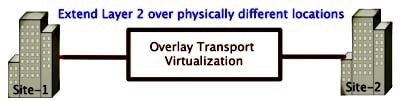
本文档介绍如何在思科聚合服务路由器(ASR)1000平台上配置重叠传输虚拟化(OTV)单播邻接服务器。由于传统OTV需要通过互联网服务提供商(ISP)云进行组播,因此单播邻接服务器允许您利用OTV功能,而无需组播支持和配置。
OTV将第2层(L2)拓扑扩展到物理上不同的站点,这允许设备在第2层通过第3层(L3)提供商通信。站点1中的设备认为它们与站点2中的设备位于同一广播域。
先决条件
要求
Cisco 建议您了解以下主题:
- 以太网虚拟连接(EVC)配置
- ASR平台上的基本L2和L3配置
使用的组件
本文档中的信息基于ASR 1002和Cisco IOS®版本asr1000rp1-adventerprise.03.09.00.S.153-2.S.bin。
要在ASR 1000和思科云服务路由器(CSR)1000V平台上实施OTV功能,您的系统必须具备以下要求:
- Cisco IOS-XE版本3.9S或更高版本
- 最大传输单位(MTU)为1542或更高
- 站点之间的单播可达性
本文档中的信息都是基于特定实验室环境中的设备编写的。本文档中使用的所有设备最初均采用原始(默认)配置。如果您使用的是真实网络,请确保您已经了解所有命令的潜在影响。
配置
具有基本L2/L3连接的网络图
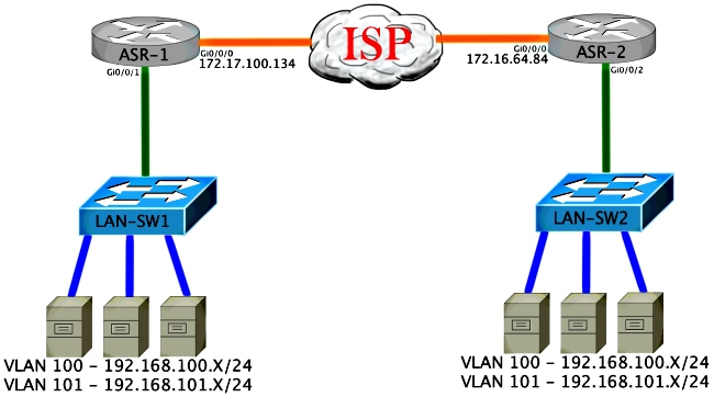
基本L2/L3连接
从基本配置开始。ASR上的内部接口配置为dot1q流量的服务实例。OTV加入接口是外部WAN第3层接口。
ASR-1
 interface GigabitEthernet0/0/0
  description OTV-WAN-Connection
  mtu 9216
  ip address 172.17.100.134 255.255.255.0
  negotiation auto
  cdp enable

 ASR-2
 interface GigabitEthernet0/0/0
  description OTV-WAN-Connection
  mtu 9216
  ip address 172.16.64.84 255.255.255.0
  negotiation auto
  cdp enable
由于OTV添加了42字节报头,因此您必须验证ISP是否从站点到站点传递了最小MTU大小。要完成此验证,请发送数据包大小为1514且设置了DF位。这为ISP提供了模拟OTV数据包所需的负载加上数据包上的“不分段”标记。如果没有DF位就无法ping通,则会出现路由问题。如果可以不执行ping操作,但无法通过DF位集执行ping操作,则表明存在MTU问题。成功后,您就可以将OTV单播模式添加到站点ASR。
ASR-1#ping 172.17.100.134 size 1514 df-bit
 Type escape sequence to abort.
 Sending 5, 1514-byte ICMP Echos to 172.17.100.134, timeout is 2 seconds:
 Packet sent with the DF bit set
 !!!!!
 Success rate is 100 percent (5/5), round-trip min/avg/max = 1/1/2 ms
内部接口是L2端口,配置了L2 dot1q标记数据包的服务实例。它构建内部站点网桥域。在本例中,它是无标记VLAN1。内部站点网桥域用于同一站点上多个OTV设备的通信。这允许他们通信并确定哪台设备是哪个网桥域的授权边缘设备(AED)。
必须将服务实例配置到使用重叠的网桥域中。
ASR-1
 interface GigabitEthernet0/0/1
  no ip address
  negotiation auto
  cdp enable
  service instance 1 ethernet
   encapsulation untagged
   bridge-domain 1
  !
  service instance 50 ethernet
   encapsulation dot1q 100
   bridge-domain 200
  !
  service instance 51 ethernet
   encapsulation dot1q 101
   bridge-domain 201


ASR-2
 interface GigabitEthernet0/0/2
  no ip address
  negotiation auto
  cdp enable
  service instance 1 ethernet
   encapsulation untagged
   bridge-domain 1
  !
  service instance 50 ethernet
   encapsulation dot1q 100
   bridge-domain 200
  !
  service instance 51 ethernet
   encapsulation dot1q 101
   bridge-domain 201
OTV单播邻接服务器最低配置
这是一个基本配置,只需几个命令即可设置邻接服务器和加入/内部接口。
配置本地站点网桥域,在本例中为LAN上的VLAN1。站点标识符特定于每个物理位置。此示例有两个彼此物理上独立的远程位置。相应地配置站点1和站点2。
ASR-1

 Config t
 otv site bridge-domain 1
 otv site-identifier 0000.0000.0001


ASR-2

 Config t
 otv site bridge-domain 1
 otv site-identifier 0000.0000.0002
为每侧构建重叠。配置重叠,应用加入接口,并将邻接服务器配置添加到每一端。本示例将ASR-1用作邻接服务器,将ASR-2用作客户端。
添加要扩展的两个网桥域。请注意,您不扩展站点网桥域,只扩展需要的两个VLAN。为重叠接口建立单独的服务实例以调用网桥域200和201。分别应用dot1q标记100和101。
ASR-1

 Config t
 interface Overlay1
  no ip address
  otv join-interface GigabitEthernet0/0/0
  otv use-adjacency-server 172.17.100.134 unicast-only
  otv adjacency-server unicast-only
    service instance 10 ethernet
     encapsulation dot1q 100
     bridge-domain 200
    service instance 11 ethernet
     encapsulation dot1q 101
     bridge-domain 201


ASR-2

 Config t
 interface Overlay1
  no ip address
  otv join-interface GigabitEthernet0/0/0
  otv use-adjacency-server 172.17.100.134 unicast-only
    service instance 10 ethernet
     encapsulation dot1q 100
     bridge-domain 200
    service instance 11 ethernet
     encapsulation dot1q 101
     bridge-domain 201
在此阶段,ASR到ASR OTV仅单播邻接关系已完成并启动。找到邻居,ASR应对需要扩展的VLAN支持AED
ASR-1#show otv
 Overlay Interface Overlay1
  VPN name                 : None
  VPN ID                   : 1
  State                    : UP
  AED Capable              : Yes
  Join interface(s)        : GigabitEthernet0/0/0
  Join IPv4 address        : 172.17.100.134
  Tunnel interface(s)      : Tunnel0
  Encapsulation format     : GRE/IPv4
  Site Bridge-Domain       : 1
  Capability               : Unicast-only
  Is Adjacency Server      : Yes
  Adj Server Configured    : Yes
 Prim/Sec Adj Svr(s)      :172.17.100.134
 ASR-1#show otv isis neigh

 Tag Overlay1:
 System Id      Type Interface   IP Address      State Holdtime Circuit Id
 ASR-2          L1   Ov1         172.16.64.84      UP    25       ASR-1.01


ASR-2#show otv
 Overlay Interface Overlay1
  VPN name                 : None
  VPN ID                   : 1
  State                    : UP
  AED Capable              : Yes
  Join interface(s)        : GigabitEthernet0/0/0
  Join IPv4 address        : 172.16.64.84
  Tunnel interface(s)      : Tunnel0
  Encapsulation format     : GRE/IPv4
  Site Bridge-Domain       : 1
  Capability               : Unicast-only
  Is Adjacency Server      : No
  Adj Server Configured    : Yes
  Prim/Sec Adj Svr(s)      : 172.17.100.134
 ASR-2#show otv isis neigh

 Tag Overlay1:
 System Id      Type Interface   IP Address      State Holdtime Circuit Id
 ASR-1          L1   Ov1         172.17.100.134    UP    8        ASR-1.01
弗里菲
使用本部分可确认配置能否正常运行。
带OTV的网络图
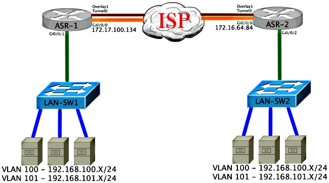
验证命令和预期输出
此输出显示VLAN 100和101已扩展。ASR是AED,输出中会显示映射VLAN的内部接口和服务实例。
ASR-1#show otv vlan
 Key:  SI - Service Instance

 Overlay 1 VLAN Configuration Information
  Inst VLAN  Bridge-Domain  Auth  Site Interface(s)
  0    100   200            yes   Gi0/0/1:SI50
  0    101   201            yes   Gi0/0/1:SI51
  Total VLAN(s): 2
  Total Authoritative VLAN(s): 2


 ASR-2#show otv vlan
 Key:  SI - Service Instance

 Overlay 1 VLAN Configuration Information
  Inst VLAN  Bridge-Domain  Auth  Site Interface(s)
  0    100   200            yes   Gi0/0/2:SI50
  0    101   201            yes   Gi0/0/2:SI51
  Total VLAN(s): 2
  Total Authoritative VLAN(s): 2
要验证VLAN是否已扩展,请执行站点到站点ping。主机192.168.100.2位于站点1,主机192.168.100.3位于站点2。当您在本地和跨OTV到另一端构建ARP时,前几个ping操作会失败。
LAN-SW1#ping 192.168.100.3
 Type escape sequence to abort.
 Sending 5, 100-byte ICMP Echos to 192.168.100.3, timeout is 2 seconds:
 ...!!
 Success rate is 40 percent (2/5), round-trip min/avg/max = 1/5/10 ms


LAN-SW1#ping 192.168.100.3
 Type escape sequence to abort.
 Sending 5, 100-byte ICMP Echos to 192.168.100.3, timeout is 2 seconds:
 !!!!!
 Success rate is 100 percent (5/5), round-trip min/avg/max = 1/4/10 ms


LAN-SW1#ping 192.168.100.3 size 1500 df-bit
 Type escape sequence to abort.
 Sending 5, 1500-byte ICMP Echos to 192.168.100.3, timeout is 2 seconds:
 Packet sent with the DF bit set
 !!!!!
 Success rate is 100 percent (5/5), round-trip min/avg/max = 1/4/10 ms
为了确保MAC表和OTV路由表与本地设备一起正确构建,并且您学习远程设备的MAC地址,请使用show otv route命令。
LAN-SW1#show int vlan 100
 Vlan100 is up, line protocol is up
   Hardware is Ethernet SVI, address is 0c27.24cf.abd1 (bia 0c27.24cf.abd1)
   Internet address is 192.168.100.2/24


LAN-SW2#show int vlan 100
 Vlan100 is up, line protocol is up
   Hardware is Ethernet SVI, address is b4e9.b0d3.6a51 (bia b4e9.b0d3.6a51)
   Internet address is 192.168.100.3/24


ASR-1#show otv route vlan 100

 Codes: BD - Bridge-Domain, AD - Admin-Distance,
        SI - Service Instance, * - Backup Route

 OTV Unicast MAC Routing Table for Overlay1

  Inst VLAN BD     MAC Address    AD    Owner  Next Hops(s)
 ----------------------------------------------------------
  0    100  200    0c27.24cf.abaf 40    BD Eng Gi0/0/1:SI50
  0    100  200    0c27.24cf.abd1 40    BD Eng Gi0/0/1:SI50 <--- Local mac is
  pointing to the physical interface
  0    100  200    b4e9.b0d3.6a04 50    ISIS   ASR-2
  0    100  200    b4e9.b0d3.6a51 50    ISIS   ASR-2              <--- Remote
  mac is pointing across OTV to ASR-2

 4 unicast routes displayed in Overlay1

 ----------------------------------------------------------
 4 Total Unicast Routes Displayed


ASR-2#show otv route vlan 100

 Codes: BD - Bridge-Domain, AD - Admin-Distance,
        SI - Service Instance, * - Backup Route

 OTV Unicast MAC Routing Table for Overlay1

  Inst VLAN BD     MAC Address    AD    Owner  Next Hops(s)
 ----------------------------------------------------------
  0    100  200    0c27.24cf.abaf 50    ISIS   ASR-1
  0    100  200    0c27.24cf.abd1 50    ISIS   ASR-1              <--- Remote
  mac is pointing across OTV to ASR-1
  0    100  200    b4e9.b0d3.6a04 40    BD Eng Gi0/0/2:SI50
  0    100  200    b4e9.b0d3.6a51 40    BD Eng Gi0/0/2:SI50 <--- Local mac is
  pointing to the physical interface

 4 unicast routes displayed in Overlay1

 ----------------------------------------------------------
 4 Total Unicast Routes Displayed
常见问题
输出中的When OTV Does Not Form错误消息指示ASR不支持AED。这意味着ASR不会通过OTV转发VLAN。造成这种情况的原因有几种,但最常见的是ASR在站点之间没有连接。检查L3连接和可能阻止的UDP端口8472(保留用于OTV)的流量。此情况的另一个可能原因是未配置内部站点网桥域。这会造成ASR无法成为AED的情况,因为它是否是站点上唯一的ASR尚不确定。
ASR-1#show otv
 Overlay Interface Overlay1
  VPN name                 : None
  VPN ID                   : 1
  State                    : UP
  AED Capable              : No, overlay DIS not elected <--- Local OTV site cannot
  see the remote neighbor
  Join interface(s)        : GigabitEthernet0/0/0
  Join IPv4 address        : 172.17.100.134
  Tunnel interface(s)      : Tunnel0
  Encapsulation format     : GRE/IPv4
  Site Bridge-Domain       : 1
  Capability               : Unicast-only
  Is Adjacency Server      : Yes
  Adj Server Configured    : Yes
  Prim/Sec Adj Svr(s)      : 172.17.100.134


ASR-2#show otv
 Overlay Interface Overlay1
  VPN name                 : None
  VPN ID                   : 1
  State                    : UP
  AED Capable              : No, overlay DIS not elected <--- Local OTV site cannot
  see the remote neighbor
  Join interface(s)        : GigabitEthernet0/0/0
  Join IPv4 address        :172.16.64.84
  Tunnel interface(s)      : Tunnel0
  Encapsulation format     : GRE/IPv4
  Site Bridge-Domain       : 1
  Capability               : Unicast-only
  Is Adjacency Server      : No
  Adj Server Configured    : Yes
  Prim/Sec Adj Svr(s)      : 172.17.100.134
故障排除
本部分提供了可用于对配置进行故障排除的信息。
在加入接口上创建数据包捕获以查看OTV Hello
您可以在ASR上使用板载数据包捕获设备来帮助排除可能的问题。
要创建访问控制列表(ACL)以尽量减少影响和过饱和捕获,请输入:
ip access-list extended CAPTURE
 permit udp host 172.17.100.134 host 172.16.64.84 eq 8472
 permit udp host 172.16.64.84 host 172.17.100.134 eq 8472
要设置捕获以在两个ASR上双向嗅探连接接口,请输入:
monitor capture 1 buffer circular access-list CAPTURE interface g0/0/0 both
要开始捕获,请输入:
monitor capture 1 start

 *Nov 14 15:21:37.746: %BUFCAP-6-ENABLE: Capture Point 1 enabled.

 <wait a few min>

 monitor capture 1 stop

 *Nov 14 15:22:03.213: %BUFCAP-6-DISABLE: Capture Point 1 disabled.

 show mon cap 1 buffer brief
缓冲区输出显示捕获出口和从邻居和本地入口中的hello。当在两个ASR上启用并双向捕获时,您会在捕获中看到相同的数据包从一端离开并进入另一端。
ASR-1中的前两个数据包未在ASR-2中捕获,因此您必须将捕获偏移三秒,以便补偿该时间和引导ASR-1输出的两个额外数据包。
ASR-1#show mon cap 1 buff bri
  -------------------------------------------------------------
  #   size   timestamp     source             destination   protocol
  -------------------------------------------------------------
    0 1464    0.000000   172.17.100.134     ->  172.16.64.84       UDP  * not in
    ASR-2 cap
    1  150    0.284034   172.17.100.134     ->  172.16.64.84       UDP  * not in
    ASR-2 cap
    2 1464    3.123047   172.17.100.134     ->  172.16.64.84       UDP
    3 1464    6.000992   172.17.100.134     ->  172.16.64.84       UDP
    4  110    6.140044   172.17.100.134     ->  172.16.64.84       UDP
    5 1464    6.507029   172.16.64.84       ->  172.17.100.134     UDP
    6 1464    8.595022   172.17.100.134     ->  172.16.64.84       UDP
    7  150    9.946994   172.17.100.134     ->  172.16.64.84       UDP
    8 1464   11.472027   172.17.100.134     ->  172.16.64.84       UDP
    9  110   14.600012   172.17.100.134     ->  172.16.64.84       UDP
   10 1464   14.679018   172.17.100.134     ->  172.16.64.84       UDP
   11 1464   15.696015   172.16.64.84       ->  172.17.100.134     UDP
   12 1464   17.795009   172.17.100.134     ->  172.16.64.84       UDP
   13  150   18.903997   172.17.100.134     ->  172.16.64.84       UDP
   14 1464   21.017989   172.17.100.134     ->  172.16.64.84       UDP
   15  110   23.151045   172.17.100.134     ->  172.16.64.84       UDP
   16 1464   24.296026   172.17.100.134     ->  172.16.64.84       UDP
   17 1464   25.355029   172.16.64.84       ->  172.17.100.134     UDP
   18 1464   27.053998   172.17.100.134     ->  172.16.64.84       UDP
   19  150   27.632023   172.17.100.134     ->  172.16.64.84       UDP
   20 1464   30.064999   172.17.100.134     ->  172.16.64.84       UDP
   21  110   32.358035   172.17.100.134     ->  172.16.64.84       UDP
   22 1464   32.737013   172.17.100.134     ->  172.16.64.84       UDP
   23 1464   32.866004   172.16.64.84       ->  172.17.100.134     UDP
   24 1464   35.338032   172.17.100.134     ->  172.16.64.84       UDP
   25  150   35.709015   172.17.100.134     ->  172.16.64.84       UDP
   26 1464   38.054990   172.17.100.134     ->  172.16.64.84       UDP
   27  110   40.121048   172.17.100.134     ->  172.16.64.84       UDP
   28 1464   41.194042   172.17.100.134     ->  172.16.64.84       UDP
   29 1464   42.196041   172.16.64.84       ->  172.17.100.134     UDP


ASR-2#show mon cap 1 buff bri
  -------------------------------------------------------------
  #   size   timestamp     source             destination   protocol
  -------------------------------------------------------------
    0 1464    0.000000   172.17.100.134     ->  172.16.64.84       UDP
    1 1464    2.878952   172.17.100.134     ->  172.16.64.84       UDP
    2  110    3.018004   172.17.100.134     ->  172.16.64.84       UDP
    3 1464    3.383982   172.16.64.84       ->  172.17.100.134     UDP
    4 1464    5.471975   172.17.100.134     ->  172.16.64.84       UDP
    5  150    6.824954   172.17.100.134     ->  172.16.64.84       UDP
    6 1464    8.349988   172.17.100.134     ->  172.16.64.84       UDP
    7  110   11.476980   172.17.100.134     ->  172.16.64.84       UDP
    8 1464   11.555971   172.17.100.134     ->  172.16.64.84       UDP
    9 1464   12.572968   172.16.64.84       ->  172.17.100.134     UDP
   10 1464   14.672969   172.17.100.134     ->  172.16.64.84       UDP
   11  150   15.780965   172.17.100.134     ->  172.16.64.84       UDP
   12 1464   17.895965   172.17.100.134     ->  172.16.64.84       UDP
   13  110   20.027998   172.17.100.134     ->  172.16.64.84       UDP
   14 1464   21.174002   172.17.100.134     ->  172.16.64.84       UDP
   15 1464   22.231998   172.16.64.84       ->  172.17.100.134     UDP
   16 1464   23.930951   172.17.100.134     ->  172.16.64.84       UDP
   17  150   24.508976   172.17.100.134     ->  172.16.64.84       UDP
   18 1464   26.942959   172.17.100.134     ->  172.16.64.84       UDP
   19  110   29.235995   172.17.100.134     ->  172.16.64.84       UDP
   20 1464   29.614973   172.17.100.134     ->  172.16.64.84       UDP
   21 1464   29.743964   172.16.64.84       ->  172.17.100.134     UDP
   22 1464   32.215992   172.17.100.134     ->  172.16.64.84       UDP
   23  150   32.585968   172.17.100.134     ->  172.16.64.84       UDP
   24 1464   34.931958   172.17.100.134     ->  172.16.64.84       UDP
   25  110   36.999008   172.17.100.134     ->  172.16.64.84       UDP
   26 1464   38.072002   172.17.100.134     ->  172.16.64.84       UDP
   27 1464   39.072994   172.16.64.84       ->  172.17.100.134     UDP
相关信息
修订历史记录
| 版本 | 发布日期 | 备注 |
|---|---|---|
1.0 |
25-Apr-2014
|
初始版本 |
 反馈
反馈