详细设计指南和使用EVPN VPWS的SR-TE显式路径策略的配置示例,IOS XR版本 — 7.5.x
下载选项
非歧视性语言
此产品的文档集力求使用非歧视性语言。在本文档集中,非歧视性语言是指不隐含针对年龄、残障、性别、种族身份、族群身份、性取向、社会经济地位和交叉性的歧视的语言。由于产品软件的用户界面中使用的硬编码语言、基于 RFP 文档使用的语言或引用的第三方产品使用的语言,文档中可能无法确保完全使用非歧视性语言。 深入了解思科如何使用包容性语言。
关于此翻译
思科采用人工翻译与机器翻译相结合的方式将此文档翻译成不同语言,希望全球的用户都能通过各自的语言得到支持性的内容。 请注意:即使是最好的机器翻译,其准确度也不及专业翻译人员的水平。 Cisco Systems, Inc. 对于翻译的准确性不承担任何责任,并建议您总是参考英文原始文档(已提供链接)。
目录
简介
本文档根据XYZ网络的要求介绍了详细设计指南及其技术说明,并为分段路由流量工程(SR-TE)显式路径策略与以太网VPN(EVPN)虚拟专用有线服务(VPWS)的使用案例提供了低级配置模板和配置。
一、背景情况
1.1.超出范围
本文档不介绍使用XTC控制器、EVPN ELAN等的集中式“按需”SR-TE策略的要求,但仅重点介绍具有EVPN VPWS重叠的前端节点驱动的SR-TE策略。
1.2.假设
本文档的读者必须熟悉IP/MPLS和以太网的概念以及分段路由和流量工程技术。
1.3.技术范围
本文档的主要技术范围限于:
- 带TI-LFA FRR的OSPF
- 前端(分布式)控制的SR-TE策略
- 显式主路径和基于IGP的动态故障切换路径
- 单宿主EVPN VPWS
本文档中提供的配置模板称为Cisco IOS®-XR 7.5.x。
1.4.文档摘要
表 1.文档节
| 主题类型 |
主题名称 |
章节编号 |
| 简介 |
背景信息 |
1 |
| 要求 |
用户要求 |
2 |
| 技术概述 |
分段路由 |
3 |
| SR-TE概述 |
4 |
|
| TI-LFA FRR |
5 |
|
| EVPN重叠 |
6 |
|
| BoB和负载均衡 |
7 |
|
| 配置模板 |
完整的设计解决方案 |
8 |
| 示例配置和show命令 |
9 |
要求
2.用户要求
2.1.要求摘要
服务提供商XYZ网络要求通过思科NCS 5500设备构建绿色现场网络。
其目的是将组播数据流(语音、视频)作为服务传输至具有特定要求的第2层传输网络,其中一种目的就是流量设计通过网络的流量路径。
他们更愿意将SR用于传输标签,SR-TE用于流量工程,并将EVPN作为重叠来提供服务标签。
2.2.使用的组件
用户XYZ已在NCS 5500路由器和线卡上融合:
表 2.项目硬件要求
| PE节点 |
PID |
| chassis |
NCS-5504 |
| 连接P节点的MPA/LC |
NC55-36X100G-A-SE |
| 连接CE节点的MPA/LC |
NC55-36X100G-A-SE |
| P节点 |
PID |
| chassis |
NCS-5508 |
| 连接其他P节点的MPA/LC |
NC55-36X100G-A-SE |
| 连接PE节点的MPA/LC |
NC55-36X100G-A-SE |
本部分概述了将使用的技术,并作简要说明。
技术概述
3.分段路由
3.1.什么是分段路由?
分段路由是最新先进的MPLS技术,它正在通过引入标签分发和流量工程来取代传统的LDP和RSVP-TE协议,并且仅通过链路状态IGP/BGP协议实现。
分段路由是根据源路由模式在网络上转发数据包的一种方法。源主机选择路径并将其编码到数据包报头中,作为有序的数据段列表。段是任何类型指令的标识符。例如,拓扑段标识通向目的地的下一跳。每个数据段由数据段ID(SID)标识,数据段ID由一个平面无符号20位整数组成。
3.2.数据段标识符
图 1.SR节点SID和邻接SID
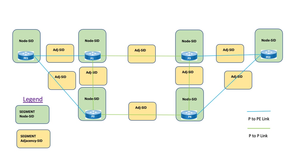
网段:内部网关协议(IGP)分配两种类型的网段:前缀网段和邻接网段。每个路由器(节点)和每条链路(邻接)都有一个关联的分段标识符(SID)。
前缀SID:前缀段是全局段,因此前缀SID在段路由域内是全局唯一的,如图1所示。前缀SID与IP前缀关联。前缀SID是从分段路由全局块(SRGB)标签范围内手动配置的,由IS-IS或OSPF分配。前缀段将流量沿最短路径引导至其目的地。
- 使用SR全局块(SRGB)
- 使用路由器功能TLV通告的SRGB — 在配置中,前缀SID可以配置为绝对值或索引
- 在协议通告中,Prefix-SID始终被编码为全局唯一索引。索引表示从SRGB基数偏移的零基编号,即0是第一个索引。例如,索引1 à SID为16,000 + 1 = 16,001
节点SID:节点SID是一种特殊类型的前缀SID,用于标识特定节点。它在环回接口下配置,以节点的环回地址作为前缀。前缀段是全局段,因此前缀SID在段路由域内是全局唯一的。
换句话说,节点段是与标识节点的主机前缀相关联的前缀段。
- 等同于router-id前缀,它是标识节点的前缀
- Node-SID是在通告中设置了N标志的前缀SID
- 默认情况下,每个已配置的Prefix-SID都是节点SID
- “regular”(即非节点SID)Prefix-SID可为IS-IS配置
邻接SID:邻接段由称为邻接SID的标签标识,该标签表示与相邻路由器之间的特定邻接(如出口接口)。邻接SID由IS-IS或OSPF分配。邻接段将流量引导至特定邻接。邻接网段是本地网段,因此邻接SID相对于特定路由器在本地是唯一的。
- 具有本地意义
- 自动为每个邻接分配
- 始终编码为绝对(即非索引)值
绑定SID或BSID:它是与SR策略关联的具有本地意义的SID。它有助于将数据包引入其关联的SR策略。 绑定段是标识SR-TE策略的本地段。每个SR-TE策略都与一个绑定段ID(BSID)关联。
BSID是本地标签,当SR-TE策略实例化时,会自动为每个SR-TE策略分配此标签。 BSID可用于引导流量进入SR-TE策略并跨越域边界,从而创建无缝的端到端域间SR-TE策略。
4. SR-TE概述
4.1.什么是SR-TE?
分段路由流量工程(SR-TE)将SR的简单无状态源路由机制转变为高级级别,对数据流量进行编程和引导,使其通过预定义路径避免拥塞,并提供备用路径,就像高速公路实时流量图一样。
当您管理性地配置通过各种限制条件的组合定义的策略时,即可实现此目的,这些限制对从源节点到目标节点的主路径以及备用路径进行编程。控制器可以是集中式(SDN)或分布式(头端),具体取决于网络需求。
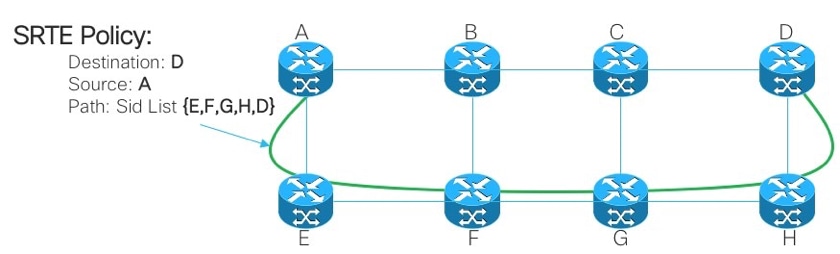
让我们考虑图2中显示的拓扑。假设链路的开销为默认值,从A到达D的最短路径为A-B-C-D,但低延迟路径为A-E-F-G-H-D。操作员可以根据要求定义流量工程路径(例如,延迟),并以数据段ID列表(A、E、F、G、H、D)的形式表示。与RSVP-TE不同,此策略的状态只在路由器A上维护,而不是数据包经过的整个路由器(即E、F、G和H)。
图 2.SR-TE管理性定义路径示例
4.2. SR-TE政策
流量工程分段路由(SR-TE)使用“策略”引导流量通过网络。SR-TE策略路径表示为指定路径的数据段列表,称为数据段ID(SID)列表。每个网段都是从源到目的地的端到端路径,指示网络中的路由器遵循指定路径,而不是遵循IGP计算得出的最短路径。如果数据包被引导进入SR-TE策略,则头端会对该数据包推送SID列表。网络的其余部分执行SID列表中嵌入的指令。
SR-TE策略被标识为有序列表(头端、颜色、端点):
- 前端 — SR-TE策略实例化的位置
- 颜色 — 用于区分对相同节点对的两个或多个策略的数值(头端 — 终端)
- 终端 — SR-TE策略的目标
- 每个SR-TE策略都有一个颜色值。相同节点对之间的每个策略都需要唯一的颜色值。
SR-TE策略配置有一个或多个候选路径,其中包括主路径和备用路径。
例如,可以使用邻接SID显式定义策略的主路径,并且在出现故障的情况下,备份路径可以是IGP度量所照顾的动态路径。
5. TI-LFA FRR
5.1.概述
拓扑无关的无环备用(TI-LFA)是一项保护链路、节点和SRLG的功能。配置简单;在路由器中实施简单TI-LFA配置只需要两行配置。它不需要对路由器中使用的现有协议进行任何更改。图3.显示了本地链路故障和节点故障场景下TI-LFA的主要流量路径和预先计算的备份路径。
图 3.TI LFA链路故障切换场景
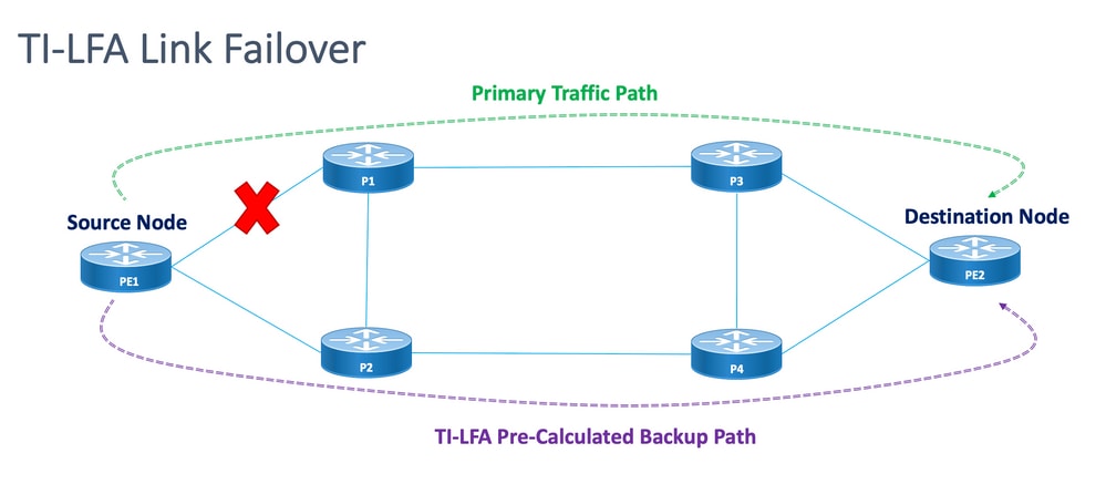
图 4.TI LFA节点故障转移方案
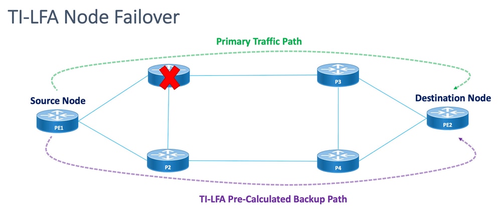
每个受保护节点和路径都有一个可以快速启用的预计算备份路径。受保护路径的收敛时间为50毫秒或更短。这意味着,即使是最延迟或数据包丢失敏感型应用,在节点或链路出现故障时,也不会出现中断。TI-LFA计算备份路径并暂时从数据库中删除受保护的链路或节点。之后,它会首先计算具有最短路径的备份路径。这可确保备份路径具有尽可能低的度量开销,同时避免使用受保护的路径。如果发生故障,会使用跟随备份路径的流量工程隧道。修复标签列表确定需要新路由的数据包的路径,以到达其目的地。修复标签列表是正常的标签堆栈,但仅在受保护路由发生故障时使用。
5.2.故障检测方法对FRR的影响
SR-TE流量工程路径的快速重新路由配置为在可行情况下从主路径到备份路径的故障切换场景中切换流量的一种方式。快速重新路由功能在IGP(OSPF/ISIS)协议下配置。收敛时间取决于进行链路故障检测的方法。如果光纤被切断,检测会立即进行,并且收敛时间小于50毫秒的可能性很高。但是,如果链路故障检测必须由BFD执行,间隔为15毫秒(乘数x3)。收敛时间大部分超过50毫秒。
5.3.使用SR避免微环路
微环路是拓扑更改(链路断开、链路打开或度量更改事件)之后网络中出现的短暂数据包环路。微环路是由网络中不同节点的非同时收敛引起的。如果节点收敛并向尚未收敛的邻居节点发送流量,流量可能会在这两个节点之间循环,从而导致数据包丢失、抖动和无序数据包。
分段路由微环路抑制功能可检测微环路后面是否可能存在拓扑更改。如果节点计算新拓扑上可能会出现微环路,则该节点会使用网段列表创建通往目的地的无环路SR-TE策略路径。在RIB更新延迟计时器到期后,SR-TE策略将替换为常规转发路径。RIB更新延迟有一个默认计时器,由TI-LFA处理。
6. EVPN重叠
EVPN最初是为以太网多点服务设计的技术,具有先进的多宿主功能,使用BGP在MPLS网络上分发MAC地址可达性信息,同时为L2VPN带来与IP VPN相同的操作和扩展特性。如今,除了DCI和E-LAN应用之外,EVPN解决方案系列为所有以太网服务类型(包括E-LINE和E-TREE)以及数据中心路由和桥接方案提供了通用基础。EVPN还提供在同一实例中合并L2和L3服务的选项。
EVPN是下一代解决方案,通过MPLS网络提供以太网多点服务。EVPN的运行与虚拟专用局域网服务(VPLS)不同,VPLS在核心中启用基于BGP控制平面的MAC学习。在EVPN中,参与EVPN实例的PE使用MP-BGP协议在控制平面中学习用户MAC路由。
如前所述,EVPN带来许多优势:
- 实现单流冗余和负载均衡
- 简化调配和操作
- 实现最优转发
- 快速收敛
- 扩展 MAC 地址
- IETF标准化下的多供应商解决方案
需要获取一台设备上获取的MAC地址,或者将其分配到VLAN中的其它设备上。EVPN软件MAC学习功能可将一台设备上学习的MAC地址分配给连接到网络的其它设备。使用BGP从远程设备获取MAC地址。
在这些部分中,您将了解EVPN的一些一般优势和路由类型,然后了解应用于XYZ网络服务设计的解决方案特定的组件。
6.1. EVPN优势
L2VPN和L3VPN不仅可以在一个解决方案保护伞下提供各种路由类型的服务,EVPN还解决了服务提供商网络中以太网服务的两个长期限制:
- 多宿主和全活动以太网接入
- 服务提供商网络 — 与中心办公室或数据中心集成
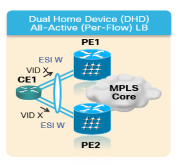
6.1.1.多宿主和全活动以太网接入
该图显示了传统的L2多点解决方案(如VPLS)的最大局限性。
图 5.EVPN全主动接入
当VPLS在核心中运行时,环路避免要求PE1/PE2和PE3/PE4仅为其各自的CE提供单主用冗余。传统上,使用mLACP等技术或传统L2协议(如MST、REP、G.8032等)提供单主用访问冗余。
分层式VPLS(H-VPLS)也出现相同的情况,其中接入节点负责通过主用和备用分支伪线(PW)提供单主用H-VPLS接入。
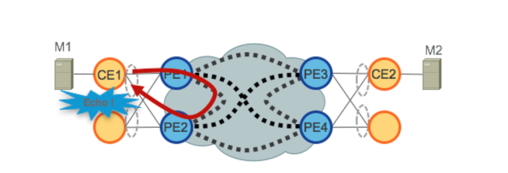
由于VPLS技术无法防止从核心中使用的某些流量类别转发机制产生的L2环路,因此无法部署全主动访问冗余模型。来自CE的广播、未知单播和组播(BUM)流量在整个VPLS核心中泛洪,由所有PE接收,然后泛洪到所有连接的CE。在我们的示例中,PE1可以将BUM流量从CE1泛洪到核心,并且PE2可以在收到流量后将其发送回CE1。
EVPN使用基于BGP的控制平面技术来解决此问题,并为以太网或H-EVPN接入启用主用 — 主用访问冗余模型。
6.2. EVPN路由类型
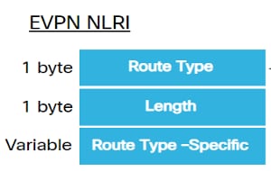
EVPN定义了用于承载所有EVPN路由的新BGP NLRI。EVPN NLRI在BGP中使用多协议扩展,AFI为25(L2VPN),SAFI为70。BGP功能通告用于确保两个扬声器支持EVPN NLRI。
图 6.EVPN NLRI
此实施所需的相关EVPN路由类型如下所述:
6.2.1.路由类型1 — 以太网自动发现(AD)路由
根据EVI和ESI通告以太网自动发现(AD)路由。这些路由是按ES发送的。它们带有属于ES的EVI列表。当CE为单宿主时,ESI字段设置为零。此路由类型用于MAC地址的大规模撤回、负载均衡的别名以及水平分割过滤。
6.2.2.路由类型4 — 以太网段路由
以太网段路由可将CE设备连接到两台或PE设备。ES路由支持发现连接到同一以太网网段的已连接PE设备,即冗余组发现。 它还用于指定转发器(DF)选举。
6.3. EVPN主机连接
支持以下EVPN模式:
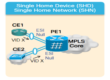
- 单宿主 — 这使您可以将用户边缘(CE)设备连接到一个提供商边缘(PE)设备。在此ESI中,每个PE-CE链路的值为空。
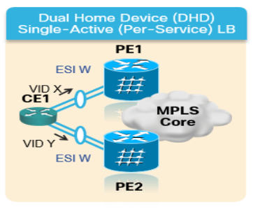
- 多宿主 — 这使您可以将一个用户边缘(CE)设备连接到两个或多个提供商边缘(PE)设备,以提供冗余连接。不需要机箱间链路。冗余PE设备可确保网络出现故障时不会出现流量中断。多宿主的类型包括:
图 7.EVPN单归属
多宿主 — 以下是多宿主的类型:
1.单主用 — 在单主用模式下,仅允许连接到特定以太网段的一组PE中的单个PE向该以太网段转发或从该以太网段转发流量。
图 8.EVPN单活动
2.主用 — 主用 — 在主用 — 主用模式下,允许连接到特定以太网网段的所有PE向该以太网网段转发流量,或从该以太网网段转发流量。
图 9EVPN双主用
7. BoB和负载均衡
7.1.捆绑包上的BFD(BoB)
双向转发检测(BFD)对相邻转发引擎之间的路径故障提供低开销短持续时间的检测。BFD允许使用单一机制在任何介质和协议层进行故障检测,检测时间和开销范围极广。如果链路或邻居发生故障,快速检测故障可立即对故障做出反应。
这将触发IGP开始将流量转发到已使用FRR(对于IGP)和PIC(对于BGP)计算的备份路径。
在BFD Over Bundle(BoB)功能中,IPv4 BFD会话将在每个活动的捆绑成员上运行。
图 10.BoB逻辑图
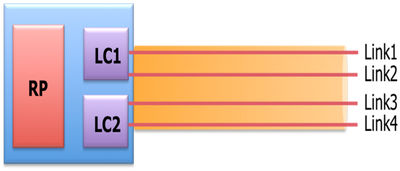
除了现有的L1/L2状态之外,Bundlemgr还考虑BFD状态,以确定成员链路可用性。捆绑成员状态是以下项的函数:
L1状态(物理链路)
L2状态(LACP)
L3状态(BFD)
BFD代理仍在线卡上运行。捆绑成员链路的BFD状态在RP上合并。成员链路必须背对背连接,中间不能有任何L2交换机。BoB功能在整个XYZ网络的所有捆绑以太网接口中配置。
7.2.负载均衡
相关网络中的每个流ECMP负载均衡跨越捆绑包间以太网接口和捆绑包内以太网(捆绑包接口的物理成员之间)。如前所述,这适用于从PE到PE(核心负载均衡)以及PE到CE(交流负载均衡)的整个网络。
7.2.1.使用FAT标签实现核心负载均衡
根据XYZ网络的范围,必须仅考虑每个流的ECMP(等价多路径)负载均衡,如前所述:
路由器通常根据标签堆栈中最靠下的标签(对于给定伪线上的所有流,该标签是同一标签)来平衡流量。这可能导致非对称负载均衡。在此情景中,流是指具有相同源和目标对的数据包序列。数据包从源提供商边缘(PE)传输到目的提供商边缘PE。
流感知传输伪线(FAT PW)能够识别伪线内的各个流,并为路由器提供使用这些流对流量进行负载均衡的能力。当使用等价多路径(ECMP)时,使用FAT PW对核心中的流量进行负载均衡。根据进入伪线的不可分数据包流创建流标签,并将其作为数据包中最下层的标签插入。路由器可以使用流标签进行负载均衡,从而在ECMP路径或核心中的链路捆绑路径之间提供更好的流量分配。
额外标签会添加到堆栈(称为流标签),该标签针对PE上的每个唯一传入流生成。流标签是区分PW内流的唯一标识符,从源MAC地址和目标MAC地址以及源IP地址和目标IP地址派生。流标签包含标签堆栈(EOS)位集的结尾。流标签插入在VC标签之后和控制词之前(如果有)。入口PE计算并转发流标签。FAT PW配置启用流标签。出口PE丢弃流标签,因此不会做出任何决策。
7.2.2.附件电路负载均衡
但是,对于AC捆绑包成员的负载均衡,您需要使用不同的方法,因为此网络部分没有SR-MPLS。
当明确调整所有PE路由器上的特定l2vpn配置旋钮时,可以实现此处的每流负载均衡。根据要求,它可以是每个SRC/DST MAC或SRC/DST IP。
配置模板 和命令示例
8.完整的设计解决方案
本节讨论由前面章节中介绍的所有不同单个组件拼接的完整设计详细信息。本部分介绍拓扑和相关配置模板(参考Cisco IOS-XR 7.5.x)。
8.1.低层次要求
对于正常流量场景,流量设计为仅在PE1和PE3的服务终端之间以及PE2和PE4之间传播。此情况的主要目标是使流量路径完全脱离,如图12所示。
此处的相关流量将通过EVPN重叠封装组播流。从CE1和CE2节点进入组播媒体流(语音/视频),在PE1和PE2节点进行封装,在PE3和PE4节点分别解封后通过EVPN L2重叠传输到CE3和CE4节点。
因此,除非另有说明,否则在所有情况下,源 — 目标流量对都视为PE1-PE3和PE2-PE4。有关要求详细信息,请参阅2.2小节。
8.2.设计总结
为了满足这些要求,XYZ网络选择OSPF作为基础IGP。要引导封装的组播流通过源 — 目标流量对所需的路径,必须在PE节点之间实施SR-TE。
SR-TE策略设计有显式路径和动态IGP路径。
显式路径包括:
- 正常流量场景
- 故障切换方案,直到备用路径选项可用
动态IGP路径包括:
- 备用路径选项不可用的故障切换方案备用路径
BFD、TI-LFA和Microloop Avoidance等功能在OSPF下配置,如配置模板子部分所示。
对于正常流量场景,第8.5.1小节中会提到配置模板和其他详细信息。
对于流量故障切换场景,配置模板和其他详细信息在子节8.5.2中介绍。
除此之外,还需要考虑在发生故障的情况下避免微环路和低于50毫秒的收敛时间等要求。
8.3.设计模块
此小节介绍所有设计块,随后在这些小节中详细介绍这些设计块。
一般设计概述(第1层):
- 整个XYZ网络的MTU大小固定为“9216”,旨在支持最多5到6个SR标签堆栈
- “BFD over Bundle”实施间隔为15毫秒以检测光纤切割为50毫秒以下
OSPF/SR-TE设计概述:
- OSPF作为IGP协议,TI-LFA配置为提供50毫秒以下收敛时间的FRR
- 基于网段路由的传输层作为转发平面,而OSPF作为路由协议
- 在XYZ网络中,分段路由流量工程显式路径会引导所有所需主路径方向的流量。在链路/节点故障切换情况下,流量通过动态igp路径路由
- 此设计还包括微环路避免和OSPF最大度量
BGP/RR设计概述:
- 集群中配置了两个RR以提供冗余
- 每个PE中的XYZ网络、BGP进程分别与两个RR形成“IPv4”和“L2VPN EVPN”对等关系
服务设计概述:
- 服务层构建在基于BGP的控制层和第2层点对点EVPN(EVPN-VPWS)之上。
- 组播视频(UDP)流量通过点对点EVPN-VPWS PW进行封装
- ECMP负载均衡通过配置EVPN部分下的FAT标签实现
- 该服务旨在支持最多5到6个SR标签堆栈,其中包括SR传输标签、EVPN标签和用于负载均衡的FAT标签
8.4.物理拓扑示例
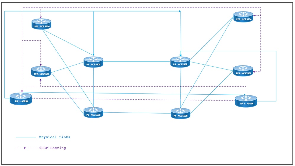
XYZ网络的物理拓扑如图所示。为简单起见,仅显示4个PE和4个P节点。有两个RR节点在集群中运行以提供冗余。
图 11.物理拓扑
8.5.第1层设计详细信息
在通用第1层设计中,有一个捆绑以太网,每个捆绑至少配置两个成员链路。要快速检测链路故障,请选择BFD,而不是捆绑功能。时间间隔可以理想地在5-15毫秒之间变化。这取决于卸载的硬件功能。
有关BFD的详细信息,请参阅https://www.cisco.com/c/en/us/td/docs/iosxr/ncs5500/routing/73x/b-routing-cg-ncs5500-73x/implementing-bfd.html。 请注意,该功能仅需在捆绑包以太网接口下配置,不需要在IGP下配置。MTU大小固定为9216,旨在支持最多5到6个SR标签堆栈。
8.5.1.配置模板
所有节点的BFD over Bundle配置模板如下所示:
interface Bundle-Ether <Intf-Number>

 bfd address-family ipv4 timers start 60

 bfd address-family ipv4 timers nbr-unconfig 60

 bfd address-family ipv4 multiplier 3

 bfd address-family ipv4 destination <Connected-Intf-IP>

 bfd address-family ipv4 fast-detect

 bfd address-family ipv4 minimum-interval <Time in msec>

 mtu <Value as per requirement>

 ipv4 address <Intf IP> <Subnet Mask>>

 bundle minimum-active links 1

!
8.6. OSPF/SR-TE设计概述
网络中的所有OSPFv2路由器都在区域0中,因此网络处理单个IGP域。
在路由器OSPF下,启用分段路由并配置相关的捆绑以太网接口。同样,在捆绑接口(Bundle Interfaces)下,启用网络类型和快速重新路由参数。最重要的是,在配置了Prefix-SID的被动模式下启用环回接口。
OSPF是一种链路状态协议,因此,必须优先立即识别下行链路,并且需要创建备份路径。为此,在Bundle Interface下配置了BFD over Bundle,在OSPF下配置了TI-LFA FRR,这样在光纤切断的情况下将收敛时间保持在50毫秒。
以下小节详细描述了流量路径的正常和故障切换场景:
8.6.1. SR-TE正常流量场景
为了维护非常严格的主路径,SR-TE策略设计为使用前面提到的源 — 目标流量对之间的端到端显式路径。此外,SR-TE策略内需要多个首选候选路径,以便为多个故障切换方案提供调配。
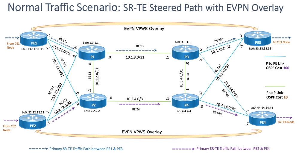
此图显示了用户网络详细信息,这些详细信息与第8.3小节中提到的设计块一致。
- PE到P和P到P节点之间的链路
- 所有节点的环回地址
- 所有节点的接口地址
- SR-TE引导的正常流量路径方向
- PE节点之间的EVPN重叠
未故意显示RR以减少拓扑中的混乱。
PE和P之间的链路标有蓝色,P和P之间的链路标有绿色。PE-to-P链路的OSPF开销是100,P-to-P链路的开销是10。
主SR-TE流量在PE1-PE3对之间使用蓝色箭头标记,在PE2-PE4对之间使用紫色箭头标记。
图 12.拓扑详细信息

8.6.1.1.配置模板
此小节包含用于PE1和PE2节点的OSPF/SR-TE的相关配置模板,如下所示:
# PE1 Node: OSPF & SR-TE configs
router ospf CORE
nsr
distribute link-state Command to distribute OSPF database into SR-TE database
log adjacency changes
router-id <Router-ID-PE1> OSPF Router-ID
segment-routing mpls
nsf cisco
microloop avoidance segment-routing Command to enable microloop avoidance with TI-LFA
area 0
interface Bundle-Ether<Intf-Number> OSPF PE to P Link
cost 100 OSPF PE to P Metric
authentication keychain <Key-Chain> Command to enable OSPF Authentication per link
network point-to-point
fast-reroute per-prefix Commands to enable TI-LFA
fast-reroute per-prefix ti-lfa enable
fast-reroute per-prefix tiebreaker node-protecting index <Index-Value>
prefix-suppression
!
interface Loopback <Loopback-ID-PE1>
passive enable
prefix-sid index <SID-Index-Number1> OSPF Loopback Prefix SID
注意:要全局配置Source-Address”命令或在POLICY下配置。作为默认行为,策略下的源地址将取代全局命令。
当在同一PE中作为SR-TE策略的源时,我们需要在多个或ISIS和OSPF都使用单独的环回运行时,在作为SR-TE策略的源时,在网段路由配置下使用source address命令(如图所示),并且需要对其中一个环回地址进行冻结。否则,在正常情况下,只有一个IGP使用唯一环回运行,则源地址配置是可选的。
segment-routing
global-block 16000 23999 Default SRGB Value (Need not be configured). Needs to be configured only if non-default value is assigned
local-block 15000 15999 Default SRLB Value (Need not be configured). Needs to be configured only if non-default value is assigned
traffic-eng
candidate-paths
all
source-address ipv4Configure SR-TE source address as OSPF loopback (Global Option)
!
!
segment-list name <SIDLIST1> Primary/Normal Path SID-LIST1
index <Index ID> mpls adjacency <Remote-IP-Address-Link1>
index <Index ID> mpls adjacency <Remote-IP-Address-Link2>
index <Index ID> mpls adjacency <Remote-IP-Address-Link3>
!
segment-list name <SIDLIST2> Primary Back Up Path SID-LIST2
index <Index ID> mpls adjacency <Remote-IP-Address-Link4>
index <Index ID> mpls adjacency <Remote-IP-Address-Link5>
index <Index ID> mpls adjacency <Remote-IP-Address-Link6>
!
segment-list name <SIDLIST3> Secondary Back Up Path SID-LIST3
index <Index ID> mpls adjacency <Remote-IP-Address-Link4>
index <Index ID> mpls adjacency <Remote-IP-Address-Link5>
index <Index ID> mpls adjacency <Remote-IP-Address-Link6>
!
policy <Pol-Name1>
source-address ipv4 Configure SR-TE source address as OSPF loopback (Policy Specific Option)
color <Color-ID> end-point ipv4 <Destn-PE3>
candidate-paths
preference 50 Tertiary Back Up Path with least preference
dynamic
metric
type igp
!
!
!
preference 100 Secondary Back Up Path with 3rd highest preference
explicit segment-list <SIDLIST3>
!
!
preference 150 Primary Back Up Path with 2nd highest preference
explicit segment-list <SIDLIST2>
!
!
preference 200 Primary/Normal Path with highest preference (Active Path for PE1 in this scenario)
explicit segment-list <SIDLIST1>
!
!
!
!
!
!
# PE2 Node: OSPF & SR-TE configs
router ospf CORE
nsr
distribute link-state Command to distribute OSPF database into SR-TE database
log adjacency changes
router-id <Router-ID-PE2> OSPF Router-ID
segment-routing mpls
nsf cisco
microloop avoidance segment-routing Command to enable microloop avoidance with TI-LFA
area 0
interface Bundle-Ether<Intf-Number> OSPF PE to P Link
cost 100 OSPF PE to P Metric
authentication keychain <Key-Chain> Command to enable OSPF Authentication per link
network point-to-point
fast-reroute per-prefix Commands to enable TI-LFA
fast-reroute per-prefix ti-lfa enable
fast-reroute per-prefix tiebreaker node-protecting index <Index-Value>
prefix-suppression
!
interface Loopback <Loopback-ID-PE2>
passive enable
prefix-sid index <SID-Index-Number2> OSPF Loopback Prefix SID
注意:已删除可选的源地址、默认SRGB和SRLB命令。
segment-routing
traffic-eng
!
!
segment-list name <SIDLIST1> Primary/Normal Path SID-LIST1
index <Index ID> mpls adjacency <Remote-IP-Address-Link1>
index <Index ID> mpls adjacency <Remote-IP-Address-Link2>
index <Index ID> mpls adjacency <Remote-IP-Address-Link3>
!
segment-list name <SIDLIST2> Primary Back Up Path SID-LIST2
index <Index ID> mpls adjacency <Remote-IP-Address-Link4>
index <Index ID> mpls adjacency <Remote-IP-Address-Link5>
index <Index ID> mpls adjacency <Remote-IP-Address-Link6>
!
segment-list name <SIDLIST3> Secondary Back Up Path SID-LIST3
index <Index ID> mpls adjacency <Remote-IP-Address-Link4>
index <Index ID> mpls adjacency <Remote-IP-Address-Link5>
index <Index ID> mpls adjacency <Remote-IP-Address-Link6>
!
policy <Pol-Name1>
source-address ipv4 Configure SR-TE source address as OSPF loopback (Policy Specific Option)
color <Color-ID> end-point ipv4 <Destn-PE4>
candidate-paths
preference 50 Tertiary Back Up Path with least preference
dynamic
metric
type igp
!
!
!
preference 100 Secondary Back Up Path with 3rd highest preference
explicit segment-list <SIDLIST3>
!
!
preference 150 Primary Back Up Path with 2nd highest preference
explicit segment-list <SIDLIST2>
!
!
preference 200 Primary/Normal Path with highest preference (Active Path for PE2 in this scenario)
explicit segment-list <SIDLIST1>
!
!
!
!
!
!
注意:在上述解决方案中,网段列表的显式跳基于IP地址,因为正如此处所述,基于“mpls label”的显式路径SR-TE策略配置在7.3.x中路径验证不适用于远程链路故障
如果除PE节点的本地链路之外的任何远程链路出现故障,则路径仍然有效。这是设计好的,在XR 7.5.x之前无法修改
# PE Node: SR-TE configs


router ospf <Process-Name>

 address-family ipv4 unicast

 area 0

  interface <Core BE Intf1>

  adjacency-sid absolute <Adj-SID1>

  interface <Core BE Intf2>

  adjacency-sid absolute < Adj-SID2>

  interface <Core BE Intf3>

  adjacency-sid absolute < Adj-SID3>


segment-routing

 traffic-eng

  policy <Pol-Name1>

   color <Color-ID> end-point ipv4 <Destn-PE>

   candidate-paths

    preference 10

     explicit segment-list <SIDLIST1>

     !

    preference 20

     dynamic

       metric

       type igp

     !

  segment-list name <SIDLIST1>

    index 10 mpls label <Adj-SID-Link1>

    index 20 mpls label <Adj-SID-Link2>

    index 30 mpls label <Adj-SID-Link3>
8.6.2.用于故障切换场景的SR-TE
要了解流量故障切换场景,必须仔细查看在正常流量状况下的主路径流量,如上一小节中的拓扑图中所述。
在发生故障切换情况时,主要目标是最大程度地保持流量路径不连续性(在给定的当前拓扑基础架构下)。XYZ网络有严格的要求管理性地引导流量通过备份路径中的特定节点,以便保持源 — 目标节点对之间的最大分离。此设计旨在避免已使用的链路过载,并尽量减少未使用的链路。
这些小节显示各种故障切换场景,例如单链路、双链路、单节点和双节点,以及流量用于保持最大不连续性的故障切换路径。
8.6.3.单链路故障转移方案
这是单链路故障场景,其中PE1和P1之间的本地链路发生故障,流量通过核心P2和P1节点绕行。这是通过segment-list <SIDLIST1>以管理方式引导的,该列表形成PE1和PE3节点之间的主备用路径
图 13.单链路故障切换场景
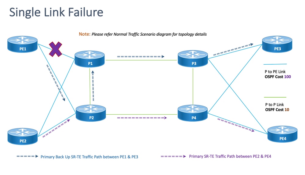
不相交性:对于单链路故障,共享的公共链路数为零(0),如上一个拓扑所示。
8.6.3.1.配置模板
此小节包含用于PE1和PE2节点的OSPF/SR-TE的相关配置模板,如下所示:
注意:PE1和PE2的路由器OSPF配置模板与正常场景类似。
# PE1 Node: OSPF & SR-TE configs
segment-routing
traffic-eng
!
!
segment-list name <SIDLIST1> Primary/Normal Path SID-LIST1
index <Index ID> mpls adjacency <Remote-IP-Address-Link1>
index <Index ID> mpls adjacency <Remote-IP-Address-Link2>
index <Index ID> mpls adjacency <Remote-IP-Address-Link3>
!
segment-list name <SIDLIST2> Primary Back Up Path SID-LIST2
index <Index ID> mpls adjacency <Remote-IP-Address-Link4>
index <Index ID> mpls adjacency <Remote-IP-Address-Link5>
index <Index ID> mpls adjacency <Remote-IP-Address-Link6>
!
segment-list name <SIDLIST3> Secondary Back Up Path SID-LIST3
index <Index ID> mpls adjacency <Remote-IP-Address-Link4>
index <Index ID> mpls adjacency <Remote-IP-Address-Link5>
index <Index ID> mpls adjacency <Remote-IP-Address-Link6>
!
policy <Pol-Name1>
source-address ipv4 Configure SR-TE source address as OSPF loopback (Policy Specific Option)
color <Color-ID> end-point ipv4 <Destn-PE3>
candidate-paths
preference 50 Tertiary Back Up Path with least preference
dynamic
metric
type igp
!
!
!
preference 100 Secondary Back Up Path with 3rd highest preference
explicit segment-list <SIDLIST3>
!
!
preference 150 Primary Back Up Path with 2nd highest preference (Active Path for PE1 in this scenario)
explicit segment-list <SIDLIST2>
!
!
preference 200 Primary/Normal Path with highest preference
explicit segment-list <SIDLIST1>
!
!
!
!
!
!
注意:PE1和PE2的路由器OSPF配置模板与正常场景类似。
# PE2 Node: OSPF & SR-TE configs
segment-routing
traffic-eng
!
!
segment-list name <SIDLIST1> Primary/Normal Path SID-LIST1
index <Index ID> mpls adjacency <Remote-IP-Address-Link1>
index <Index ID> mpls adjacency <Remote-IP-Address-Link2>
index <Index ID> mpls adjacency <Remote-IP-Address-Link3>
!
segment-list name <SIDLIST2> Primary Back Up Path SID-LIST2
index <Index ID> mpls adjacency <Remote-IP-Address-Link4>
index <Index ID> mpls adjacency <Remote-IP-Address-Link5>
index <Index ID> mpls adjacency <Remote-IP-Address-Link6>
!
segment-list name <SIDLIST3> Secondary Back Up Path SID-LIST3
index <Index ID> mpls adjacency <Remote-IP-Address-Link4>
index <Index ID> mpls adjacency <Remote-IP-Address-Link5>
index <Index ID> mpls adjacency <Remote-IP-Address-Link6>
!
policy <Pol-Name1>
source-address ipv4 Configure SR-TE source address as OSPF loopback (Policy Specific Option)
color <Color-ID> end-point ipv4 <Destn-PE4>
candidate-paths
preference 50 Tertiary Back Up Path with least preference
dynamic
metric
type igp
!
!
!
preference 100 Secondary Back Up Path with 3rd highest preference
explicit segment-list <SIDLIST3>
!
!
preference 150 Primary Back Up Path with 2nd highest preference
explicit segment-list <SIDLIST2>
!
!
preference 200 Primary/Normal Path with highest preference (Active Path for PE2 in this scenario)
explicit segment-list <SIDLIST1>
!
!
!
!
!
!
8.6.4.双链路故障转移方案
这是双链路故障场景,其中PE1和P1之间的本地链路和PE2和P2之间的本地链路发生故障。来自PE1的流量通过核心P2和P1节点绕行,而来自PE2的流量通过核心P1和P2节点绕行。
它们通过PE1和PE2各自的segment-list <SIDLIST2>进行管理性导向,分别形成PE1和PE3以及PE2和PE4节点之间的备用路径。
图 14.双链路故障切换场景
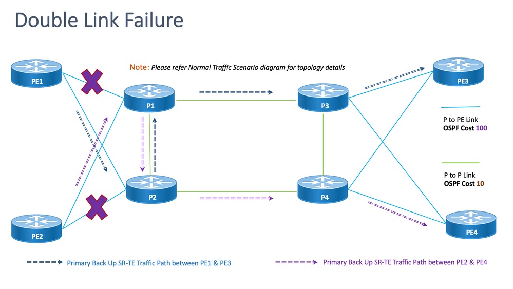
脱节:对于双链路故障,共享的公共链路数为一(1),如上述拓扑所示。
8.6.4.1.配置模板
此小节包含用于PE1和PE2节点的OSPF/SR-TE的相关配置模板,如下所示:
注意:PE1和PE2的路由器OSPF配置模板与正常场景类似。
# PE1 Node: OSPF & SR-TE configs

#show run router ospf


router ospf CORE

 distribute link-state

 log adjacency changes

 router-id 11.11.11.11

 segment-routing mpls

 microloop avoidance segment-routing

 area 0

  interface Bundle-Ether11

   cost 100

   authentication keychain XYZ-CONT-PE1

   network point-to-point

   fast-reroute per-prefix

   fast-reroute per-prefix ti-lfa enable

   fast-reroute per-prefix tiebreaker node-protecting index 200

   prefix-suppression

  !

  interface Bundle-Ether12

   cost 100

   authentication keychain XYZ-CONT-PE1

   network point-to-point

   fast-reroute per-prefix

   fast-reroute per-prefix ti-lfa enable

   fast-reroute per-prefix tiebreaker node-protecting index 200

   prefix-suppression

  !

  interface Loopback0

   passive enable

   prefix-sid index 11

  !

 !

!
segment-routing
traffic-eng
!
!
segment-list name <SIDLIST1> Primary/Normal Path SID-LIST1
index <Index ID> mpls adjacency <Remote-IP-Address-Link1>
index <Index ID> mpls adjacency <Remote-IP-Address-Link2>
index <Index ID> mpls adjacency <Remote-IP-Address-Link3>
!
segment-list name <SIDLIST2> Primary Back Up Path SID-LIST2
index <Index ID> mpls adjacency <Remote-IP-Address-Link4>
index <Index ID> mpls adjacency <Remote-IP-Address-Link5>
index <Index ID> mpls adjacency <Remote-IP-Address-Link6>
!
segment-list name <SIDLIST3> Secondary Back Up Path SID-LIST3
index <Index ID> mpls adjacency <Remote-IP-Address-Link4>
index <Index ID> mpls adjacency <Remote-IP-Address-Link5>
index <Index ID> mpls adjacency <Remote-IP-Address-Link6>
!
policy <Pol-Name1>
source-address ipv4 Configure SR-TE source address as OSPF loopback (Policy Specific Option)
color <Color-ID> end-point ipv4 <Destn-PE3>
candidate-paths
preference 50 Tertiary Back Up Path with least preference
dynamic
metric
type igp
!
!
!
preference 100 Secondary Back Up Path with 3rd highest preference
explicit segment-list <SIDLIST3>
!
!
preference 150 Primary Back Up Path with 2nd highest preference (Active Path for PE1 in this scenario)
explicit segment-list <SIDLIST2>
!
!
preference 200 Primary/Normal Path with highest preference
explicit segment-list <SIDLIST1>
!
!
!
!
!
!
注意:PE1和PE2的路由器OSPF配置模板与正常场景类似。
# PE2 Node: OSPF & SR-TE configs
segment-routing
traffic-eng
!
!
segment-list name <SIDLIST1> Primary/Normal Path SID-LIST1
index <Index ID> mpls adjacency <Remote-IP-Address-Link1>
index <Index ID> mpls adjacency <Remote-IP-Address-Link2>
index <Index ID> mpls adjacency <Remote-IP-Address-Link3>
!
segment-list name <SIDLIST2> Primary Back Up Path SID-LIST2
index <Index ID> mpls adjacency <Remote-IP-Address-Link4>
index <Index ID> mpls adjacency <Remote-IP-Address-Link5>
index <Index ID> mpls adjacency <Remote-IP-Address-Link6>
!
segment-list name <SIDLIST3> Secondary Back Up Path SID-LIST3
index <Index ID> mpls adjacency <Remote-IP-Address-Link4>
index <Index ID> mpls adjacency <Remote-IP-Address-Link5>
index <Index ID> mpls adjacency <Remote-IP-Address-Link6>
!
policy <Pol-Name1>
source-address ipv4 Configure SR-TE source address as OSPF loopback (Policy Specific Option)
color <Color-ID> end-point ipv4 <Destn-PE4>
candidate-paths
preference 50 Tertiary Back Up Path with least preference
dynamic
metric
type igp
!
!
!
preference 100 Secondary Back Up Path with 3rd highest preference
explicit segment-list <SIDLIST3>
!
!
preference 150 Primary Back Up Path with 2nd highest preference (Active Path for PE2 in this scenario)
explicit segment-list <SIDLIST2>
!
!
preference 200 Primary/Normal Path with highest preference
explicit segment-list <SIDLIST1>
!
!
!
!
!
!
8.6.5.单节点故障转移方案
这是单节点故障场景,其中节点P1发生故障,流量通过核心P2和P4节点绕行。这是通过segment-list <SIDLIST3>以管理方式引导的,该列表形成PE1和PE3节点之间的备用路径。
但是,PE2和PE4之间的流量仍与本拓扑中所示的主路径相同。
图 15.单节点故障转移方案
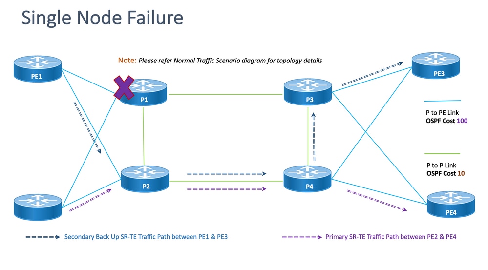
脱节:对于单节点故障,共享的公共链路数为一(1),如上述拓扑所示。
8.6.5.1.配置模板
此小节包含用于PE1和PE2节点的OSPF/SR-TE的相关配置模板,如下所示:
注意:PE1和PE2的路由器OSPF配置模板与正常场景类似。
segment-routing
traffic-eng
!
!
segment-list name <SIDLIST1> Primary/Normal Path SID-LIST1
index <Index ID> mpls adjacency <Remote-IP-Address-Link1>
index <Index ID> mpls adjacency <Remote-IP-Address-Link2>
index <Index ID> mpls adjacency <Remote-IP-Address-Link3>
!
segment-list name <SIDLIST2> Primary Back Up Path SID-LIST2
index <Index ID> mpls adjacency <Remote-IP-Address-Link4>
index <Index ID> mpls adjacency <Remote-IP-Address-Link5>
index <Index ID> mpls adjacency <Remote-IP-Address-Link6>
!
segment-list name <SIDLIST3> Secondary Back Up Path SID-LIST3
index <Index ID> mpls adjacency <Remote-IP-Address-Link4>
index <Index ID> mpls adjacency <Remote-IP-Address-Link5>
index <Index ID> mpls adjacency <Remote-IP-Address-Link6>
!
policy <Pol-Name1>
source-address ipv4 Configure SR-TE source address as OSPF loopback (Policy Specific Option)
color <Color-ID> end-point ipv4 <Destn-PE3>
candidate-paths
preference 50 Tertiary Back Up Path with least preference
dynamic
metric
type igp
!
!
!
preference 100 Secondary Back Up Path with 3rd highest preference (Active Path for PE1 in this scenario)
explicit segment-list <SIDLIST3>
!
!
preference 150 Primary Back Up Path with 2nd highest preference
explicit segment-list <SIDLIST2>
!
!
preference 200 Primary/Normal Path with highest preference
explicit segment-list <SIDLIST1>
!
!
!
!
!
!
注意:PE1和PE2的路由器OSPF配置模板与正常场景类似。
# PE2 Node: OSPF & SR-TE configs
segment-routing
traffic-eng
!
!
segment-list name <SIDLIST1> Primary/Normal Path SID-LIST1
index <Index ID> mpls adjacency <Remote-IP-Address-Link1>
index <Index ID> mpls adjacency <Remote-IP-Address-Link2>
index <Index ID> mpls adjacency <Remote-IP-Address-Link3>
!
segment-list name <SIDLIST2> Primary Back Up Path SID-LIST2
index <Index ID> mpls adjacency <Remote-IP-Address-Link4>
index <Index ID> mpls adjacency <Remote-IP-Address-Link5>
index <Index ID> mpls adjacency <Remote-IP-Address-Link6>
!
segment-list name <SIDLIST3> Secondary Back Up Path SID-LIST3
index <Index ID> mpls adjacency <Remote-IP-Address-Link4>
index <Index ID> mpls adjacency <Remote-IP-Address-Link5>
index <Index ID> mpls adjacency <Remote-IP-Address-Link6>
!
policy <Pol-Name1>
source-address ipv4 Configure SR-TE source address as OSPF loopback (Policy Specific Option)
color <Color-ID> end-point ipv4 <Destn-PE4>
candidate-paths
preference 50 Tertiary Back Up Path with least preference
dynamic
metric
type igp
!
!
!
preference 100 Secondary Back Up Path with 3rd highest preference
explicit segment-list <SIDLIST3>
!
!
preference 150 Primary Back Up Path with 2nd highest preference
explicit segment-list <SIDLIST2>
!
!
preference 200 Primary/Normal Path with highest preference (Active Path for PE2 in this scenario)
explicit segment-list <SIDLIST1>
!
!
!
!
!
!
8.6.6.双节点故障转移方案
这是双节点故障场景,节点P1和P3发生故障,流量通过核心P2和P4节点绕行。这是通过segment-list <SIDLIST3>以管理方式引导的,该列表形成PE1和PE3节点之间的备用路径。由于显式路径仅针对前面提到的2种场景进行定义,因此,此处动态IGP路径形成第三备用路径,并承担通过P2和P4节点路由流量的角色。
但是,PE2和PE4之间的流量仍与本拓扑中所示的主路径相同。
图 16.双节点故障切换场景。
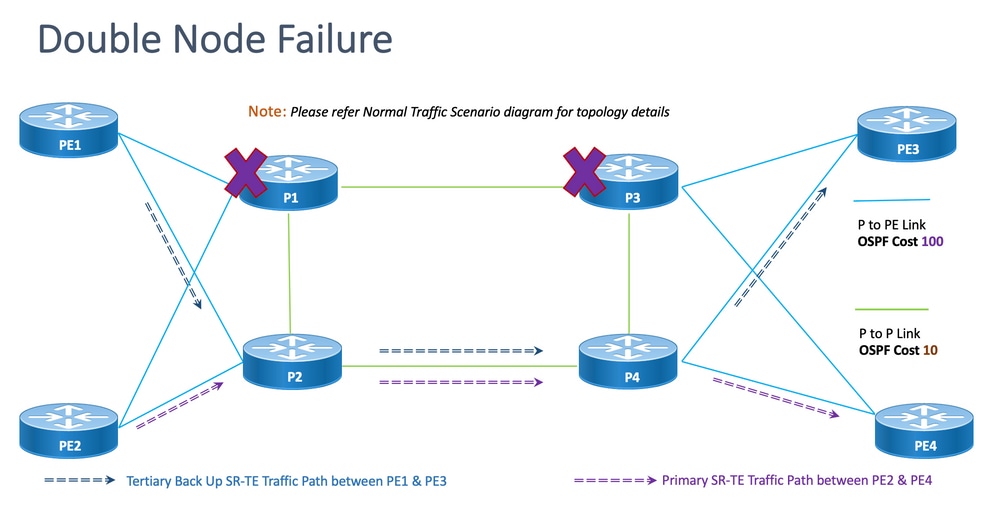
脱节:对于双节点故障,共享的公共链路数为一(1),如本拓扑所示。
8.6.6.1.配置模板
此小节包含用于PE1和PE2节点的OSPF/SR-TE的相关配置模板,如下所示:
注意:PE1和PE2的路由器OSPF配置模板与正常场景类似。
# PE1 Node: OSPF & SR-TE configs
segment-routing
traffic-eng
!
!
segment-list name <SIDLIST1> Primary/Normal Path SID-LIST1
index <Index ID> mpls adjacency <Remote-IP-Address-Link1>
index <Index ID> mpls adjacency <Remote-IP-Address-Link2>
index <Index ID> mpls adjacency <Remote-IP-Address-Link3>
!
segment-list name <SIDLIST2> Primary Back Up Path SID-LIST2
index <Index ID> mpls adjacency <Remote-IP-Address-Link4>
index <Index ID> mpls adjacency <Remote-IP-Address-Link5>
index <Index ID> mpls adjacency <Remote-IP-Address-Link6>
!
segment-list name <SIDLIST3> Secondary Back Up Path SID-LIST3
index <Index ID> mpls adjacency <Remote-IP-Address-Link4>
index <Index ID> mpls adjacency <Remote-IP-Address-Link5>
index <Index ID> mpls adjacency <Remote-IP-Address-Link6>
!
policy <Pol-Name1>
source-address ipv4 Configure SR-TE source address as OSPF loopback (Policy Specific Option)
color <Color-ID> end-point ipv4 <Destn-PE3>
candidate-paths
preference 50 Tertiary Back Up Path with least preference (Active Path for PE1 in this scenario -
Policy chooses Least Cost IGP Back Up Path in absence of Valid Explicit Path)
dynamic
metric
type igp
!
!
!
preference 100 Secondary Back Up Path with 3rd highest preference
explicit segment-list <SIDLIST3>
!
!
preference 150 Primary Back Up Path with 2nd highest preference
explicit segment-list <SIDLIST2>
!
!
preference 200 Primary/Normal Path with highest preference
explicit segment-list <SIDLIST1>
!
!
!
!
!
!
注意:PE1和PE2的路由器OSPF配置模板与正常场景类似。
# PE2 Node: OSPF & SR-TE configs
segment-routing
traffic-eng
!
!
segment-list name <SIDLIST1> Primary/Normal Path SID-LIST1
index <Index ID> mpls adjacency <Remote-IP-Address-Link1>
index <Index ID> mpls adjacency <Remote-IP-Address-Link2>
index <Index ID> mpls adjacency <Remote-IP-Address-Link3>
!
segment-list name <SIDLIST2> Primary Back Up Path SID-LIST2
index <Index ID> mpls adjacency <Remote-IP-Address-Link4>
index <Index ID> mpls adjacency <Remote-IP-Address-Link5>
index <Index ID> mpls adjacency <Remote-IP-Address-Link6>
!
segment-list name <SIDLIST3> Secondary Back Up Path SID-LIST3
index <Index ID> mpls adjacency <Remote-IP-Address-Link4>
index <Index ID> mpls adjacency <Remote-IP-Address-Link5>
index <Index ID> mpls adjacency <Remote-IP-Address-Link6>
!
policy <Pol-Name1>
source-address ipv4 Configure SR-TE source address as OSPF loopback (Policy Specific Option)
color <Color-ID> end-point ipv4 <Destn-PE4>
candidate-paths
preference 50 Tertiary Back Up Path with least preference
dynamic
metric
type igp
!
!
!
preference 100 Secondary Back Up Path with 3rd highest preference
explicit segment-list <SIDLIST3>
!
!
preference 150 Primary Back Up Path with 2nd highest preference
explicit segment-list <SIDLIST2>
!
!
preference 200 Primary/Normal Path with highest preference (Active Path for PE2 in this scenario)
explicit segment-list <SIDLIST1>
!
!
!
!
!
!
8.7. BGP/RR设计概述
边界网关协议(BGP)是在Internet上做出核心路由决策的协议。它维护一个表,其中包含IP网络或“前缀”,这些前缀表示自治系统(AS)之间的网络可达性。它被描述为路径矢量协议。BGP不使用传统的内部网关协议(IGP)度量,而是根据路径、网络策略和/或规则集做出路由决策。因此,更适合将其称为可达性协议,而不是路由协议。
MP-BGP可用于通过网络传播IPv4、IPv6、VPNv4、VPNv6、EVPN和链路状态前缀。这通过路由反射器设置完成,该设置与核心、汇聚、接入设备和SR-PCE设备形成iBGP邻居。
通过RR,BGP学习的前缀通过iBGP在内部传播。BGP路由不会重分发到IGP。路由反射器完全与数据平面隔离,专用于控制平面目的。
8.7.1.配置模板
此子部分包含BGP/RR的相关配置模板,如下所示:
# PE Node: Relevant BGP configs
router bgp <PE-ASN>
address-family l2vpn evpn
!
neighbor-group <RR-EVPN> Neighbor group of Route Reflector (RR)
remote-as <RR-ASN>
update-source <PE-Self-Loopback>
!
address-family l2vpn evpn AF L2VPN EVPN Neighborship with RR
maximum-prefix <PREFIX> <PERCENT> warning-only
!
address-family ipv4 rt-filter
!
neighbor <RR1-Loopback> Neighborship with RR1 using the above neighbor group
use neighbor-group <RR-EVPN>
neighbor <RR2-Loopback> Neighborship with RR2 using the above neighbor group
use neighbor-group <RR-EVPN>
# RR Nodes: Relevant BGP configs
router bgp <RR-ASN>
address-family l2vpn evpn
!
neighbor-group <PE-EVPN> Neighbor group of Provider Edge (PE)
remote-as <PE-ASN>
update-source <RR-Self-Loopback>
!
address-family l2vpn evpn AF L2VPN EVPN Neighborship with PE
route-reflector-client
!
address-family ipv4 rt-filter
!
neighbor <PE1-Loopback> Neighborship with PE1 using the above neighbor group
use neighbor-group <PE-EVPN>
neighbor <PE2-Loopback> Neighborship with PE2 using the above neighbor group
use neighbor-group <PE-EVPN>
8.8.服务设计概述
此小节介绍EVPN VPWS重叠服务,以及支持的标签堆栈和配置模板的表示。
EVPN-VPWS是点对点服务的BGP控制平面解决方案。它实现了在一对PE之间建立EVPN实例的信令和封装技术。它能够将流量从一个网络转发到另一个网络,而无需进行MAC查找。使用EVPN进行VPWS无需为点对点以太网服务发送单网段和多网段PW。EVPN-VPWS技术适用于IP和MPLS核心;IP核心支持BGP和MPLS核心,用于在终端之间交换数据包。
8.8.1.标签堆栈表示
该服务旨在支持最多5到6个SR标签堆栈,包括SR传输标签、EVPN标签和用于负载均衡的FAT标签。这是流量流经显式主路径的正常场景中分析的最大标签数:
| ADJ SID1 |
|
| ADJ SID2 |
|
| ADJ SID3 |
|
| EVPN标签 |
|
| 流标签(S=1) |
这是故障切换方案中流量流经备份显式路径或IGP定义的动态备份路径的已分析最大标签数:
| TI-LFA SID1 |
| TI-LFA SID2 |
| TI-LFA SID3 |
| EVPN标签 |
| 流标签(S=1) |
8.8.2.配置模板
此小节包含EVPN-VPWS的相关配置模板,如下所示:
# PE Node: EVPN configs
evpn
evi <EVI-ID> Ethernet Virtual Identifier
bgp
rd <RD-Value>
route-target import <RT-Value>
route-target export <RT-Value>
!
load-balancing
flow-label static Generates bottom-most label (S=1) for load balancing between intra & inter BE end-to-end
!
!
interface <AC-Interface>
l2vpn
pw-class <PW-Class-Name1>
encapsulation mpls
preferred-path sr-te policy <Pol-Name1> Attaching SR-TE policy as the traffic path of EVPN
!
!
xconnect group <Group-Name>
p2p <P2P-Name>
interface <AC-Subinterface> EVPN Attachment Circuit Interface towards CE
neighbor evpn evi <EVI-ID> service <Service-ID> Service ID defined should match at both the end PEs
pw-class <PW-Class-Name1>
!
9.示例配置和Show命令
最后一部分仅包含正常流量场景下PE节点的相关配置和show命令。此处捕获的参数与下图中给出的参数一致,作为参考,可帮助您了解前面部分中介绍的配置模板。
9.1. PE节点的配置示例
图 17.包含配置参数的拓扑。
# PE1 Node: OSPF & SR-TE Config
#show run router ospf
router ospf CORE
distribute link-state Command to distribute OSPF database into SR-TE database
log adjacency changes
router-id 11.11.11.11 OSPF Router ID
segment-routing mpls
microloop avoidance segment-routing Command to enable microloop avoidance with TI-LFA
area 0
interface Bundle-Ether111 OSPF PE to P Link
cost 100 OSPF PE to P Metric
authentication keychain XYZ-CONT-PE1 Command to enable OSPF Authentication per link
network point-to-point
fast-reroute per-prefix Commands to enable TI-LFA
fast-reroute per-prefix ti-lfa enable
fast-reroute per-prefix tiebreaker node-protecting index 200
prefix-suppression
!
interface Bundle-Ether211
cost 100
authentication keychain XYZ-CONT-PE1
network point-to-point
fast-reroute per-prefix
fast-reroute per-prefix ti-lfa enable
fast-reroute per-prefix tiebreaker node-protecting index 200
prefix-suppression
!
interface Loopback0
passive enable
prefix-sid index 11 OSPF Loopback Prefix SID
!
!
!
#show run segment-routing
Sat Apr 16 23:22:42.727 UTC
segment-routing
traffic-eng
segment-list PrimaryPath Primary/Normal Path
index 10 mpls adjacency 10.1.11.0
index 20 mpls adjacency 10.1.3.1
index 30 mpls adjacency 10.3.13.1
!
segment-list PrimaryBackUpPath Primary Back Up Path
index 10 mpls adjacency 10.2.11.0
index 20 mpls adjacency 10.1.2.0
index 30 mpls adjacency 10.1.3.1
!
segment-list SecondaryBackUpPath Secondary Back Up Path
index 10 mpls adjacency 10.2.11.0
index 20 mpls adjacency 10.2.4.1
index 30 mpls adjacency 10.3.4.0
!
policy SR-TE_POLICY_PE1-to-PE3 SR-TE Policy Towards PE3
color 10 end-point ipv4 33.33.33.33 SR-TE Policy End-Point PE3 Loopback
candidate-paths
preference 50 Tertiary Back Up Dynamic IGP Path with 4th highest preference
dynamic
metric
type igp
!
!
!
preference 100 Secondary Back Up Path with 3rd highest preference
explicit segment-list SecondaryBackUpPath
!
!
preference 150 Primary Back Up Path with 2nd highest preference
explicit segment-list PrimaryBackUpPath
!
!
preference 200 Primary and Active Path with highest preference
explicit segment-list PrimaryPath
!
!
!
!
!
!
# PE2 Node: OSPF & SR-TE Config
#show run router ospf
router ospf CORE
distribute link-state Command to distribute OSPF database into SR-TE database
log adjacency changes
router-id 22.22.22.22 OSPF Router ID
segment-routing mpls
microloop avoidance segment-routing Command to enable microloop avoidance with TI-LFA
area 0
interface Bundle-Ether112 OSPF PE to P Link
cost 100 OSPF PE to P Metric
authentication keychain XYZ-CONT-PE2
network point-to-point
fast-reroute per-prefix Commands to enable TI-LFA
fast-reroute per-prefix ti-lfa enable
fast-reroute per-prefix tiebreaker node-protecting index 200
prefix-suppression
!
interface Bundle-Ether222
cost 100
authentication keychain XYZ-CONT-PE2 Command to enable OSPF Authentication per link
network point-to-point
fast-reroute per-prefix Commands to enable TI-LFA
fast-reroute per-prefix ti-lfa enable
fast-reroute per-prefix tiebreaker node-protecting index 200
prefix-suppression
!
interface Loopback0
passive enable
prefix-sid index 22 OSPF Loopback Prefix SID
!
!
!
#show run segment-routing
Sat Apr 16 23:22:42.727 UTC
segment-routing
traffic-eng
segment-list PrimaryPath Primary/Normal Path
index 10 mpls adjacency 10.2.12.0
index 20 mpls adjacency 10.2.4.1
index 30 mpls adjacency 10.4.14.1
!
segment-list PrimaryBackUpPath Primary Back Up Path
index 10 mpls adjacency 10.1.12.0
index 20 mpls adjacency 10.1.2.1
index 30 mpls adjacency 10.2.4.1
!
segment-list SecondaryBackUpPath Secondary Back Up Path
index 10 mpls adjacency 10.1.12.0
index 20 mpls adjacency 10.1.3.1
index 30 mpls adjacency 10.3.4.1
!
policy SR-TE_POLICY_PE2-to-PE4 SR-TE Policy Towards PE4
color 10 end-point ipv4 44.44.44.44 SR-TE Policy End-Point PE4 Loopback
candidate-paths
preference 50 Tertiary Back Up Dynamic IGP Path with 4th highest preference
dynamic
metric
type igp
!
!
!
preference 100 Secondary Back Up Path with 3rd highest preference
explicit segment-list SecondaryBackUpPath
!
!
preference 150 Primary Back Up Path with 2nd highest preference
explicit segment-list PrimaryBackUpPath
!
!
preference 200 Primary and Active Path with highest preference
explicit segment-list PrimaryPath
!
!
!
!
!
!
# PE1 Node: BGP Config
#show run router bgp
router bgp 64848
bgp router-id 11.11.11.11 BGP Router-ID
address-family l2vpn evpn
!
neighbor-group RR-EVPN
remote-as 64848
update-source Loopback0
address-family l2vpn evpn BGP AF L2VPN EVPN
!
!
neighbor 10.10.10.10 Neighbor Route Reflector
use neighbor-group RR-EVPN
!
!
# PE2 Node: BGP Config
#show run router bgp
router bgp 64848
bgp router-id 22.22.22.22 BGP Router-ID
address-family l2vpn evpn
!
neighbor-group RR-EVPN
remote-as 64848
update-source Loopback0
address-family l2vpn evpn BGP AF L2VPN EVPN
!
!
neighbor 10.10.10.10 Neighbor Route Reflector
use neighbor-group RR-EVPN
!
!
# PE1 Node: EVPN-VPWS Config
evpn
evi 100 Ethernet Virtual Identifier
bgp
rd 11:11
route-target import 100:100
route-target export 100:100
!
load-balancing Generates bottom-most label (S=1) for load balancing between intra & inter BE end-to-end
flow-label static
!
!
interface Bundle-Ether99 Interface Attachment Circuit
ethernet-segment
identifier type 0 00.00.00.00.00.00.00.00.00
!
!
!
# PE2 Node: EVPN-VPWS Config
evpn
evi 100 Ethernet Virtual Identifier
bgp
rd 11:11
route-target import 100:100
route-target export 100:100
!
load-balancing Generates bottom-most label (S=1) for load balancing between intra & inter BE end-to-end
flow-label static
!
!
interface Bundle-Ether99 Interface Attachment Circuit
ethernet-segment
identifier type 0 00.00.00.00.00.00.00.00.00
!
!
!
9.1.在PE节点上的相关show命令
# PE1 Node: SR-TE Show Command
#show segment-routing traffic-eng policy
Sat Apr 16 23:35:32.731 UTC
SR-TE policy database
---------------------
Color: 10, End-point: 33.33.33.33
Name: srte_c_10_ep_33.33.33.33
Status:
Admin: up Operational: up for 00:12:54 (since Apr 16 23:22:38.278)
Candidate-paths:
Preference: 200 (configuration) (active) Active Path (Path in use)
Name: SR-TE_POLICY_PE1-to-PE3
Requested BSID: dynamic
Protection Type: protected-preferred
Maximum SID Depth: 12
Explicit: segment-list PrimaryPath (valid) Only the Active Path shows valid
Weight: 1, Metric Type: TE
24007 [Adjacency-SID, 10.1.11.0 - 10.1.11.1]
24007 [Adjacency-SID, 10.1.3.0 - 10.1.3.1]
24005 [Adjacency-SID, 10.3.13.0 - 10.3.13.1]
Preference: 150 (configuration)
Name: SR-TE_POLICY_PE1-to-PE3
Requested BSID: dynamic
Protection Type: protected-preferred
Maximum SID Depth: 12
Explicit: segment-list PrimaryBackUpPath (invalid) All inactive paths show invalid
Weight: 1, Metric Type: TE
Preference: 100 (configuration)
Name: SR-TE_POLICY_PE1-to-PE3
Requested BSID: dynamic
Protection Type: protected-preferred
Maximum SID Depth: 12
Explicit: segment-list SecondaryBackUpPath (invalid)
Weight: 1, Metric Type: TE
Preference: 50 (configuration) All inactive paths show invalid
Name: SR-TE_POLICY_PE1-to-PE3
Requested BSID: dynamic
Protection Type: protected-preferred
Maximum SID Depth: 12
Dynamic (invalid)
Metric Type: IGP, Path Accumulated Metric: 0
Attributes:
Binding SID: 24020
Forward Class: Not Configured
Steering labeled-services disabled: no
Steering BGP disabled: no
IPv6 caps enable: yes
Invalidation drop enabled: no
# PE2 Node: SR-TE Show Command
#show segment-routing traffic-eng policy
Sat Apr 16 23:35:32.731 UTC
SR-TE policy database
---------------------
Color: 10, End-point: 44.44.44.44
Name: srte_c_10_ep_44.44.44.44
Status:
Admin: up Operational: up for 00:12:54 (since Apr 16 23:22:38.278)
Candidate-paths:
Preference: 200 (configuration) (active) Active Path (Path in use)
Name: SR-TE_POLICY_PE1-to-PE3
Requested BSID: dynamic
Protection Type: protected-preferred
Maximum SID Depth: 12
Explicit: segment-list PrimaryPath (valid) Only the Active Path shows valid
Weight: 1, Metric Type: TE
24007 [Adjacency-SID, 10.2.12.0 - 10.2.12.1]
24007 [Adjacency-SID, 10.2.4.0 - 10.2.4.1]
24005 [Adjacency-SID, 10.4.14.0 - 10.4.14.1]
Preference: 150 (configuration)
Name: SR-TE_POLICY_PE1-to-PE3
Requested BSID: dynamic
Protection Type: protected-preferred
Maximum SID Depth: 12
Explicit: segment-list PrimaryBackUpPath (invalid) All inactive paths show invalid
Weight: 1, Metric Type: TE
Preference: 100 (configuration)
Name: SR-TE_POLICY_PE1-to-PE3
Requested BSID: dynamic
Protection Type: protected-preferred
Maximum SID Depth: 12
Explicit: segment-list SecondaryBackUpPath (invalid)
Weight: 1, Metric Type: TE
Preference: 50 (configuration) All inactive paths show invalid
Name: SR-TE_POLICY_PE1-to-PE3
Requested BSID: dynamic
Protection Type: protected-preferred
Maximum SID Depth: 12
Dynamic (invalid)
Metric Type: IGP, Path Accumulated Metric: 0
Attributes:
Binding SID: 24020
Forward Class: Not Configured
Steering labeled-services disabled: no
Steering BGP disabled: no
IPv6 caps enable: yes
Invalidation drop enabled: no
# PE1 Node: BGP Show Command


#show bgp l2vpn evpn summary

Sun Apr 17 07:16:23.574 UTC


Address Family: L2VPN EVPN

--------------------------


BGP router identifier 11.11.11.11, local AS number 64848

BGP generic scan interval 60 secs

Non-stop routing is enabled

BGP table state: Active

Table ID: 0x0   RD version: 0

BGP main routing table version 25

BGP NSR Initial initsync version 1 (Reached)

BGP NSR/ISSU Sync-Group versions 25/0

BGP scan interval 60 secs


BGP is operating in STANDALONE mode.


Process       RcvTblVer   bRIB/RIB   LabelVer  ImportVer  SendTblVer  StandbyVer

Speaker              25         25         25         25          25          25


Neighbor        Spk    AS MsgRcvd MsgSent   TblVer  InQ OutQ  Up/Down  St/PfxRcd

10.10.10.10      0  64848    9500    9484       25    0    0    5d16h          1


# PE2 Node: BGP Show Command


#show bgp l2vpn evpn summary

Sun Apr 17 07:16:23.574 UTC


Address Family: L2VPN EVPN

--------------------------


BGP router identifier 22.22.22.22, local AS number 64848

BGP generic scan interval 60 secs

Non-stop routing is enabled

BGP table state: Active

Table ID: 0x0   RD version: 0

BGP main routing table version 25

BGP NSR Initial initsync version 1 (Reached)

BGP NSR/ISSU Sync-Group versions 25/0

BGP scan interval 60 secs
BGP在独立模式下运行。
Process       RcvTblVer   bRIB/RIB   LabelVer  ImportVer  SendTblVer  StandbyVer

Speaker              25         25         25         25          25          25


Neighbor        Spk    AS MsgRcvd MsgSent   TblVer  InQ OutQ  Up/Down  St/PfxRcd

10.10.10.10      0  64848    9500    9484       25    0    0    5d16h          1
故障排除
目前没有针对此配置的故障排除信息。
相关信息
- https://www.cisco.com/c/en/us/td/docs/routers/asr9000/software/asr9k-r7-5/segment-routing/configuration/guide/b-segment-routing-cg-asr9000-75x/about-segment-routing.html
- https://www.cisco.com/c/en/us/td/docs/routers/asr9000/software/asr9k-r7-5/lxvpn/configuration/guide/b-l2vpn-cg-asr9000-75x/evpn-features.html
- 技术支持和文档 - Cisco Systems
修订历史记录
| 版本 | 发布日期 | 备注 |
|---|---|---|
1.0 |
01-Jul-2022
|
初始版本 |
 反馈
反馈