在IOS-XE上使用PIM-SM的组播服务反射:组播到单播
下载选项
非歧视性语言
此产品的文档集力求使用非歧视性语言。在本文档集中,非歧视性语言是指不隐含针对年龄、残障、性别、种族身份、族群身份、性取向、社会经济地位和交叉性的歧视的语言。由于产品软件的用户界面中使用的硬编码语言、基于 RFP 文档使用的语言或引用的第三方产品使用的语言,文档中可能无法确保完全使用非歧视性语言。 深入了解思科如何使用包容性语言。
关于此翻译
思科采用人工翻译与机器翻译相结合的方式将此文档翻译成不同语言,希望全球的用户都能通过各自的语言得到支持性的内容。 请注意:即使是最好的机器翻译,其准确度也不及专业翻译人员的水平。 Cisco Systems, Inc. 对于翻译的准确性不承担任何责任,并建议您总是参考英文原始文档(已提供链接)。
简介
本文的目的是通过配置实验指南的形式,让您了解使用IOS-XE平台的MSR(组播服务复制)的基本工作原理。
先决条件
要求
对PIM-SM的基本了解
使用的组件
ASR1000(R2和R4)、ISR4300(R3)、ISR2900(R1和R5)
配置
我们会根据以下用于传输组播的图解方案显示以下端到端配置。
网络图
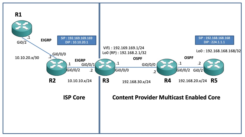
配置
在上图中,节点R1充当接收器,该接收器应只从组播源获取单播组播数据馈送。
节点R5充当组播源,生成来自其loopback 0接口的组播ICMP流量。
节点R2位于Content providers组播核心域下,并且运行有OSPF基础的PIM-SM。
节点R3充当运行组播服务复制应用的路由器,在本例中是组播边界路由器,组播数据流量应从此点转换为单播数据包,到达接收方。它将OSPF和EIGRP分别用于内容提供商和ISP,并将RP(Rendezvouz点)置于组播核心域中的环回接口上。
节点R4在ISP核心控制下,没有启用组播,只能知道如何使用底层EIGRP路由到达R3节点。
下面,您可以找到上述拓扑图中显示的节点上的相关配置:
R1:
!
no ip domain lookup
ip cef
no ipv6 cef
!
interface GigabitEthernet0/2
 ip address 10.10.20.1 255.255.255.0
 duplex auto
 speed auto
end
!
router eigrp 100
 network 10.10.20.0 0.0.0.255
!
R2:
!
interface GigabitEthernet0/0/0
 ip address 10.10.20.2 255.255.255.0
 negotiation auto
!
interface GigabitEthernet0/0/2
 ip address 10.10.10.1 255.255.255.0
 negotiation auto
!
router eigrp 100
 network 10.10.10.0 0.0.0.255
 network 10.10.20.0 0.0.0.255
!
R3:
!
ip multicast-routing distributed
!
interface Loopback0
 ip address 192.168.2.1 255.255.255.255
 ip pim sparse-mode
 ip ospf 1 area 0
!
interface GigabitEthernet0/0/0
 ip address 192.168.30.1 255.255.255.0
 ip pim sparse-mode
 ip ospf 1 area 0
 negotiation auto
!
interface GigabitEthernet0/0/1
 ip address 10.10.10.2 255.255.255.0
 negotiation auto
!
interface Vif1
 ip address 192.169.169.1 255.255.255.0
 ip pim sparse-mode
 ip service reflect GigabitEthernet0/0/0 destination 224.1.1.0 to 10.10.20.0 mask-len 24 source 192.169.169.169 <<<<
 ip igmp static-group 224.1.1.1
 ip ospf 1 area 0
!
router eigrp 100
 network 10.10.10.0 0.0.0.255
!
router ospf 1
!
ip pim rp-address 192.168.2.1
!
R4:
!
ip multicast-routing distributed
!
interface GigabitEthernet0/0/0
 ip address 192.168.30.2 255.255.255.0
 ip pim sparse-mode
 ip ospf 1 area 0
 negotiation auto
!
interface GigabitEthernet0/0/2
 ip address 192.168.20.1 255.255.255.0
 ip pim sparse-mode
 ip ospf 1 area 0
 negotiation auto
!
router ospf 1
!
ip pim rp-address 192.168.2.1
!
R5:
!
ip multicast-routing
ip cef
no ipv6 cef
!
interface Loopback0
 ip address 192.168.168.168 255.255.255.255
 ip pim sparse-mode
 ip ospf 1 area 0
!
interface GigabitEthernet0/2
 ip address 192.168.20.2 255.255.255.0
 ip pim sparse-mode
 ip ospf 1 area 0
 duplex auto
 speed auto
!
router ospf 1
!
ip pim rp-address 192.168.2.1
!
验证
我们可以执行测试ping来模拟来自R5路由器的组播流量,该路由器的loopback 0接口[192.168.168.168]的源指向组播地址224.1.1.1。然后检查运行MSR应用的节点上的mroute条目,即R3 :
R5(config)#do ping 224.1.1.1 sou lo 0 rep 10000000
Type escape sequence to abort.
Sending 10000000, 100-byte ICMP Echos to 224.1.1.1, timeout is 2 seconds:
Packet sent with a source address of 192.168.168.168
.............................
R3#sh ip mroute 224.1.1.1
IP Multicast Routing Table
Flags: D - Dense, S - Sparse, B - Bidir Group, s - SSM Group, C - Connected,
L - Local, P - Pruned, R - RP-bit set, F - Register flag,
T - SPT-bit set, J - Join SPT, M - MSDP created entry, E - Extranet,
X - Proxy Join Timer Running, A - Candidate for MSDP Advertisement,
U - URD, I - Received Source Specific Host Report,
Z - Multicast Tunnel, z - MDT-data group sender,
Y - Joined MDT-data group, y - Sending to MDT-data group,
G - Received BGP C-Mroute, g - Sent BGP C-Mroute,
N - Received BGP Shared-Tree Prune, n - BGP C-Mroute suppressed,
Q - Received BGP S-A Route, q - Sent BGP S-A Route,
V - RD & Vector, v - Vector, p - PIM Joins on route,
x - VxLAN group, c - PFP-SA cache created entry
Outgoing interface flags: H - Hardware switched, A - Assert winner, p - PIM Join
Timers: Uptime/Expires
Interface state: Interface, Next-Hop or VCD, State/Mode
(*, 224.1.1.1), 00:47:41/stopped, RP 192.168.2.1, flags: SJC
Incoming interface: Null, RPF nbr 0.0.0.0
Outgoing interface list:
Vif1, Forward/Sparse, 00:46:36/00:01:23 <<<<
(192.168.168.168, 224.1.1.1), 00:00:20/00:02:43, flags: T
Incoming interface: GigabitEthernet0/0/0, RPF nbr 192.168.30.2
Outgoing interface list:
Vif1, Forward/Sparse, 00:00:20/00:02:39 <<<<R3#sh ip mroute 224.1.1.1 count
Use "show ip mfib count" to get better response time for a large number of mroutes.
IP Multicast Statistics
3 routes using 2938 bytes of memory
2 groups, 0.50 average sources per group
Forwarding Counts: Pkt Count/Pkts per second/Avg Pkt Size/Kilobits per second
Other counts: Total/RPF failed/Other drops(OIF-null, rate-limit etc)
Group: 224.1.1.1, Source count: 1, Packets forwarded: 1455, Packets received: 1458 <<<<
RP-tree: Forwarding: 1/0/100/0, Other: 1/0/0
Source: 192.168.168.168/32, Forwarding: 1454/1/113/0, Other: 1457/3/0
R3#sh ip mroute 224.1.1.1 count
Use "show ip mfib count" to get better response time for a large number of mroutes.
IP Multicast Statistics
3 routes using 2938 bytes of memory
2 groups, 0.50 average sources per group
Forwarding Counts: Pkt Count/Pkts per second/Avg Pkt Size/Kilobits per second
Other counts: Total/RPF failed/Other drops(OIF-null, rate-limit etc)
Group: 224.1.1.1, Source count: 1, Packets forwarded: 1465, Packets received: 1468 <<<<
RP-tree: Forwarding: 1/0/100/0, Other: 1/0/0
Source: 192.168.168.168/32, Forwarding: 1464/1/113/0, Other: 1467/3/0此外,您还可以使用IOS-XE路由器上的EPC(嵌入式数据包捕获)功能捕获数据包,以验证数据包是否确实被转换为R2节点上的预定单播目的地址:
R2#mon cap TAC int gi 0/0/2 both match any
R2#mon cap TAC buff siz 50 circular
R2#mon cap TAC start
Started capture point : TAC
R2#
*Aug 12 06:50:40.195: %BUFCAP-6-ENABLE: Capture Point TAC enabled.
R2#sh mon cap TAC buff br | i ICMP
   6  114   10.684022   192.169.169.169  ->  10.10.20.1       0  BE   ICMP <<<<
   7  114   10.684022   192.169.169.169  ->  10.10.20.1       0  BE   ICMP <<<<
   8  114   12.683015   192.169.169.169  ->  10.10.20.1       0  BE   ICMP <<<<
   9  114   12.683015   192.169.169.169  ->  10.10.20.1       0  BE   ICMP <<<<
这里需要注意的重要一点是,在“实验室环境”中定期执行组播ICMP ping时,通常预期收到从接收端发回源的ICMP回应应答数据包,假设两者(源设备和接收设备)之间完全可访问。 但是,在此场景中,必须注意的是,即使我们一直尝试为组播ICMP数据包(即192.169.169.169)通告NATted源地址,直到接收方(即R1)通过EIGRP,单播ICMP回应应答仍不会通过R3路由器,因为MSR应用节点上未配置反向NAT。我们可以通过尝试将R3上Vif 1接口的EIGRP路由通告发送到EIGRP(ISP核心路由)来测试这一点:
ISR4351(config)#router eigrp 100
ISR4351(config-router)#network 192.169.169.0 0.0.0.255 <<<<
现在,我们可以检查在R2节点上捕获的ICMP回应应答发送到R3:
R2#sh mon cap TAC buff br | i ICMP

 249  114  317.847948   192.169.169.169  ->  10.10.20.1       0  BE   ICMP
 250  114  317.847948   192.169.169.169  ->  10.10.20.1       0  BE   ICMP
 251  114  317.847948   10.10.20.1       ->  192.169.169.169  0  BE   ICMP <<<<
 252  114  317.847948   10.10.20.1       ->  192.169.169.169  0  BE   ICMP <<<<
 253  114  319.847948   192.169.169.169  ->  10.10.20.1       0  BE   ICMP
 254  114  319.847948   192.169.169.169  ->  10.10.20.1       0  BE   ICMP
 255  114  319.848955   10.10.20.1       ->  192.169.169.169  0  BE   ICMP <<<<
 256  114  319.848955   10.10.20.1       ->  192.169.169.169  0  BE   ICMP <<<<
 259  114  321.848955   192.169.169.169  ->  10.10.20.1       0  BE   ICMP
 260  114  321.848955   192.169.169.169  ->  10.10.20.1       0  BE   ICMP
 261  114  321.848955   10.10.20.1       ->  192.169.169.169  0  BE   ICMP <<<<
 262  114  321.848955   10.10.20.1       ->  192.169.169.169  0  BE   ICMP <<<<
但是ping操作仍会失败,如源R5上所示:
R5(config)#do ping 224.1.1.1 sou lo 0 rep 10000000
Type escape sequence to abort.
Sending 10000000, 100-byte ICMP Echos to 224.1.1.1, timeout is 2 seconds:
Packet sent with a source address of 192.168.168.168
......................................................................
......................................................................
现在,为了让应答一直到达源地址,我们可以在MSR应用节点R3上配置NAT端口转发,通过配置可扩展NAT,将目标流量转换为192.169.169.169到192.168.168.168:
R3(config)#int gi 0/0/1
R3(config-if)#ip nat out
R3(config-if)#int gi 0/0/0
R3(config-if)#ip nat ins
R3(config-if)#exit
R3(config)#ip nat inside source static 192.168.168.168 192.169.169.169 extendable <<<<
现在检查源R5节点后,我们可以看到响应返回:
R5(config)#do ping 224.1.1.1 sou lo 0 rep 10000000
Type escape sequence to abort.
Sending 10000000, 100-byte ICMP Echos to 224.1.1.1, timeout is 2 seconds:
Packet sent with a source address of 192.168.168.168
......................................................................

Reply to request 716 from 10.10.20.1, 1 ms
Reply to request 716 from 10.10.20.1, 1 ms
Reply to request 717 from 10.10.20.1, 1 ms
Reply to request 717 from 10.10.20.1, 1 ms
Reply to request 718 from 10.10.20.1, 1 ms
Reply to request 718 from 10.10.20.1, 1 ms
上述步骤仅用于解释数据包流,并了解如何为数据流量和下游组播流量建立反向单播路径/流。因为在常规生产方案中,您通常不会遇到服务器/源端运行的组播应用需要从接收方以单播形式发送反向确认数据包的情况/实例。
通过上述测试和验证,它应简要概述如何在一个组播边界节点上运行组播服务复制应用,以及如何部署上述相同应用以将其扩展为大规模部署。
 反馈
反馈