简介
本文档介绍静态路由,并通过问题场景来说明何时需要指定到达下一跳 IP 地址的方式。
先决条件
要求
本文档没有任何特定的要求。
使用的组件
本文档不限于特定的软件和硬件版本。
本文档中的信息都是基于特定实验室环境中的设备编写的。本文档中使用的所有设备最初均采用原始(默认)配置。如果您的网络处于活动状态,请确保您了解所有命令的潜在影响。
背景信息
静态路由有多种用途,如果没有到目的 IP 地址的动态路由,或要重写动态学习路由,则通常会使用静态路由。
默认情况下,静态路由的管理距离为 1,因此优先于来自任何动态路由协议的路由。当管理距离的值增大到超过动态路由协议时,静态路由可以作为动态路由失效时的安全网络。例如,增强型内部网关路由协议 (EIGRP) 派生路由的内部路由默认管理距离为 90,外部路由默认管理距离为 170。要配置由 EIGRP 路由重写的静态路由,请将静态路由的管理距离指定为大于 170。
具有较大管理距离的静态路由称为浮动静态路由。只有在动态学习路由消失时,才会将其安装在路由表中。浮动静态路由的示例如下:ip route 172.31.10.0 255.255.255.0 10.10.10.2 101.
注意:255 的管理距离被认为是不可访问的,且管理距离为 255 的静态路由从不输入到路由表中。
规则
有关文档规则的详细信息,请参阅 Cisco 技术提示规则。
不含下一跳 IP 地址的接口的静态路由
您可以配置到接口的静态路由,而不指定下一跳IP地址。这适用于接口为点对点接口的所有情况。如果接口是多路访问接口(例如以太网接口),则不建议这样做。仅当接口处于活动状态时,才会将指向接口的静态路由插入到路由表中。建议不要使用指向没有下一跳地址的以太网接口的静态路由,因为当静态路由指向某个接口且没有下一跳信息时,路由器会认为路由范围内的每台主机都通过此接口直接连接。此类静态路由的示例包括:ip route 0.0.0.0 0.0.0.0 Ethernet0。
使用这种配置时,路由器会针对通过默认路由找到的每个目的地在以太网上执行地址解析协议(ARP),因为路由器认为所有这些目的地都直接连接到Ethernet0。这种静态路由类型,尤其是当许多数据包使用它到达许多不同的目的子网时,会导致处理器使用率高和ARP缓存非常大(以及内存分配失败)。 因此,不建议使用这种静态路由。
在直连接口上指定下一跳地址时,路由器不会为每个目的地址执行 ARP。例如 IP route 0.0.0.0 0.0.0.0 Ethernet0 192.168.1.1。
您可以仅指定直连的下一跳地址,而无需接口,但由于本文档中所述的原因,不建议这样做。
无需指定直连的下一跳地址,远程下一跳地址和可以指定远程下一跳递归的接口。
如果下一跳的接口可能关闭,而通过递归路由可以到达下一跳,则应同时指定下一跳 IP 地址和可用于查找下一跳的备用接口。例如,IP路由10.0.0.1 255.255.255.255 Serial 3/3 192.168.20.1。添加备用接口使静态路由安装更加确定。
浮动静态路由示例
本示例描述浮动静态路由的使用,并说明使用静态路由命令指定出站接口和下一跳地址的必要性。
问题
根据如图所示的网络配置,主机 172.31.10.1 可以连接到互联网。在此示例中,该主机连接到远程互联网主机 10.100.1.1:
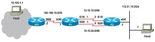
在此配置下,主链路是 R1 上串行端口 1/0 与 R2 上串行端口 1/0 之间的链路,用于从主机 172.31.10.1 向互联网传递流量。主机 10.100.1.1 是作为互联网主机的一个示例。R1 上串行端口 2/0 与 R2 上串行端口 2/0 之间的链路是备份链路。仅在主链路失效时才使用备份链路。这是使用指向主链路的静态路由和指向备份链路的浮动静态路由来部署的。
R1上有两条通往同一目的地(172.31.10.0/24)的静态路由。一条路由是常规静态路由,另一条路由是浮动静态路由,它是LAN上通往目的网络的备份,也就是冗余路径。此情景中的问题是,当主链路关闭时,系统不会在路由表中安装浮动静态路由。
这是 R1 上的配置:
hostname R1
!
interface Serial1/0
 ip address 10.10.10.1 255.255.255.252
!
interface Serial2/0
 ip address 10.10.20.1 255.255.255.252
!
ip route 10.0.0.0 255.0.0.0 192.168.10.2

! This is the primary route to get to hosts on the internet.

ip route 172.31.10.0 255.255.255.0 10.10.10.2

! This is the preferred route to the LAN.

ip route 172.31.10.0 255.255.255.0 10.10.20.2 250

! This is the floating static route to the LAN.
这是 R2 上的配置:
hostname R2
!
interface Serial1/0
 ip address 10.10.10.2 255.255.255.252
!
interface Serial2/0
 ip address 10.10.20.2 255.255.255.252
!
ip route 0.0.0.0 0.0.0.0 10.10.10.1
ip route 0.0.0.0 0.0.0.0 10.10.20.1 250
!
这是 R1 的路由表:
R1#show ip route
Codes: L - local, C - connected, S - static, R - RIP, M - mobile, B - BGP
       D - EIGRP, EX - EIGRP external, O - OSPF, IA - OSPF inter area
       N1 - OSPF NSSA external type 1, N2 - OSPF NSSA external type 2
       E1 - OSPF external type 1, E2 - OSPF external type 2
       i - IS-IS, su - IS-IS summary, L1 - IS-IS level-1, L2 - IS-IS level-2
       ia - IS-IS inter area, * - candidate default, U - per-user static route
       o - ODR, P - periodic downloaded static route, H - NHRP, l - LISP
       a - application route
       + - replicated route, % - next hop override

Gateway of last resort is not set

     10.0.0.0/8 is variably subnetted, 5 subnets, 3 masks
S       10.0.0.0/8 [1/0] via 192.168.10.2
C       10.10.10.0/30 is directly connected, Serial1/0
L       10.10.10.1/32 is directly connected, Serial1/0
C       10.10.20.0/30 is directly connected, Serial2/0
L       10.10.20.1/32 is directly connected, Serial2/0
     172.31.0.0/24 is subnetted, 1 subnets
S       172.31.10.0 [1/0] via 10.10.10.2
     192.168.10.0/24 is variably subnetted, 2 subnets, 2 masks
C       192.168.10.0/30 is directly connected, Serial3/0
L       192.168.10.1/32 is directly connected, Serial3/0
当从主机对互联网主机 10.100.1.1 执行 ping 操作时,它按预期运行。
host#ping 10.100.1.1
Type escape sequence to abort.
Sending 5, 100-byte ICMP Echos to 10.100.1.1, timeout is 2 seconds:
!!!!!
Success rate is 100 percent (5/5), round-trip min/avg/max = 73/78/80 ms
从主机到互联网主机 10.100.1.1 的跟踪路由显示:
host#traceroute 10.100.1.1
Type escape sequence to abort.
Tracing the route to 10.100.1.1
VRF info: (vrf in name/id, vrf out name/id)
1 172.31.10.2 1 msec 1 msec 1 msec
2 10.10.10.1 31 msec 39 msec 39 msec
3 192.168.10.2 80 msec * 80 msec
使用的主链路是 10.10.10.0/30。
如果关闭R1的串行端口1/0以测试故障切换,则预计R1会安装通往本地LAN 172.31.10.0的浮动静态路由,而R2会安装通过10.10.20.1通向0.0.0.0的浮动静态路由。还预计流量会通过备用链路流动。
R1#conf t
Enter configuration commands, one per line. End with CNTL/Z.
R1(config)#interface serial1/0
R1(config-if)#shutdown
R1(config-if)#end
R1#
但是,局域网 172.31.10.0/24 的静态路由仍保留在 R1 的路由表中:
R1#show ip route
Codes: L - local, C - connected, S - static, R - RIP, M - mobile, B - BGP
       D - EIGRP, EX - EIGRP external, O - OSPF, IA - OSPF inter area
       N1 - OSPF NSSA external type 1, N2 - OSPF NSSA external type 2
       E1 - OSPF external type 1, E2 - OSPF external type 2
       i - IS-IS, su - IS-IS summary, L1 - IS-IS level-1, L2 - IS-IS level-2
       ia - IS-IS inter area, * - candidate default, U - per-user static route
       o - ODR, P - periodic downloaded static route, H - NHRP, l - LISP
       a - application route
       + - replicated route, % - next hop override

Gateway of last resort is not set

     10.0.0.0/8 is variably subnetted, 3 subnets, 3 masks
S       10.0.0.0/8 [1/0] via 192.168.10.2
C       10.10.20.0/30 is directly connected, Serial2/0
L       10.10.20.1/32 is directly connected, Serial2/0
     172.31.0.0/24 is subnetted, 1 subnets
S       172.31.10.0 [1/0] via 10.10.10.2
     192.168.10.0/24 is variably subnetted, 2 subnets, 2 masks
C       192.168.10.0/30 is directly connected, Serial3/0
L       192.168.10.1/32 is directly connected, Serial3/0
R1#show ip route 172.31.10.0
Routing entry for 172.31.10.0/24
Known via "static", distance 1, metric 0
Routing Descriptor Blocks:
* 10.10.10.2
     Route metric is 0, traffic share count is 1

R1#show ip route 10.10.10.2
Routing entry for 10.0.0.0/8
Known via "static", distance 1, metric 0
Routing Descriptor Blocks:
* 192.168.10.2
     Route metric is 0, traffic share count is 1
来自主机的 ping 操作和跟踪路由不再起作用:
host#ping 10.100.1.1
Type escape sequence to abort.
Sending 5, 100-byte ICMP Echos to 10.100.1.1, timeout is 2 seconds:
.....
Success rate is 0 percent (0/5)

host#traceroute 10.100.1.1
Type escape sequence to abort.
Tracing the route to 10.100.1.1
VRF info: (vrf in name/id, vrf out name/id)
1 172.31.10.2 1 msec 1 msec 1 msec
2 * * *
3 * * *
4 * * *
5 * * *
6 * * *
7 * * *
8 * * *
9 * * *
10 * * *
11 * * *
…
浮动静态路由没有安装在 R1 上,并且主静态路由仍然位于 R1 的路由表中,即使串行端口 1/0 链路已关闭。发生这种情况的原因是静态路由在本质上是递归的。只要有到达下一跳的路由,就始终将静态路由保留在路由表中。
在此问题场景中,您可能会认为由于主链路断开,因此R1的路由表中已经安装了管理距离为250的浮动静态路由。但是,浮动静态路由没有安装到路由表中,因为常规静态路由仍然保留在路由表中。下一跳 IP 地址 10.10.10.2 成功通过路由表中的静态路由 10.0.0.0/8 递归到 192.168.10.2。
解决方案
在下一跳不能递归到其他静态路由的 R1 上配置静态路由。思科建议您为静态路由同时配置出站接口和下一跳 IP 地址。对于串行接口,指定出站接口即可,因为串行接口是点对点接口。如果出站接口是以太网接口,则同时配置出站接口和下一跳 IP 地址。
以下示例中,为局域网配置静态路由时指定了出站接口:
R1#conf t
Enter configuration commands, one per line. End with CNTL/Z.
R1(config)#no ip route 172.31.10.0 255.255.255.0 10.10.10.2
R1(config)#ip route 172.31.10.0 255.255.255.0 Serial1/0
R1(config)#end
R1#show ip route
Codes: L - local, C - connected, S - static, R - RIP, M - mobile, B - BGP
       D - EIGRP, EX - EIGRP external, O - OSPF, IA - OSPF inter area
       N1 - OSPF NSSA external type 1, N2 - OSPF NSSA external type 2
       E1 - OSPF external type 1, E2 - OSPF external type 2
       i - IS-IS, su - IS-IS summary, L1 - IS-IS level-1, L2 - IS-IS level-2
       ia - IS-IS inter area, * - candidate default, U - per-user static route
       o - ODR, P - periodic downloaded static route, H - NHRP, l - LISP
       a - application route
       + - replicated route, % - next hop override

Gateway of last resort is not set

     10.0.0.0/8 is variably subnetted, 3 subnets, 3 masks
S       10.0.0.0/8 [1/0] via 192.168.10.2
C       10.10.20.0/30 is directly connected, Serial2/0
L       10.10.20.1/32 is directly connected, Serial2/0
     172.31.0.0/24 is subnetted, 1 subnets
S       172.31.10.0 [250/0] via 10.10.20.2
     192.168.10.0/24 is variably subnetted, 2 subnets, 2 masks
C       192.168.10.0/30 is directly connected, Serial3/0
L       192.168.10.1/32 is directly connected, Serial3/0
从主机到互联网主机的 ping 操作和跟踪路由现在正常运行,并使用备份链路:
R1#show ip route 172.31.10.0
Routing entry for 172.31.10.0/24
Known via "static", distance 250, metric 0 (connected)
Routing Descriptor Blocks:
* 10.10.20.2
     Route metric is 0, traffic share count is 1
host#ping 10.100.1.1
Type escape sequence to abort.
Sending 5, 100-byte ICMP Echos to 10.100.1.1, timeout is 2 seconds:
!!!!!
Success rate is 100 percent (5/5), round-trip min/avg/max = 76/79/80 ms

host#traceroute 10.100.1.1
Type escape sequence to abort.
Tracing the route to 10.100.1.1
VRF info: (vrf in name/id, vrf out name/id)
1 172.31.10.2 1 msec 1 msec 1 msec
2 10.10.20.1 38 msec 39 msec 40 msec
3 192.168.10.2 80 msec * 80 msec
结论
思科强烈建议您在配置静态路由时指定出站接口和下一跳 IP 地址。如果出站接口是点对点类型的链路(例如,串行链路),则不需要指定下一跳 IP 地址。
 反馈
反馈