Inleiding
In dit document wordt beschreven hoe u de configuraties moet structureren om Inter VLAN-routing in te stellen met behulp van een externe Cisco-router.
Voorwaarden
Vereisten
Cisco raadt je aan om kennis te hebben van dit onderwerp:
- Basiskennis van routering
Gebruikte componenten
De informatie in dit document is gebaseerd op de volgende softwareversies:
- Catalyst Switch Cisco IOS® 15.2e
- Cisco Router Cisco IOS 17.3
De informatie in dit document is gebaseerd op de apparaten in een specifieke laboratoriumomgeving. Alle apparaten die in dit document worden beschreven, hadden een opgeschoonde (standaard)configuratie. Als uw netwerk live is, moet u zorgen dat u de potentiële impact van elke opdracht begrijpt.
Conventies
Raadpleeg Cisco Technical Tips Conventions (Conventies voor technische tips van Cisco) voor meer informatie over documentconventies.
Achtergrondinformatie
Dit document beschrijft de configuraties voor het instellen van Inter VLAN-routering met behulp van een externe Cisco-router en legt het uit met voorbeeldconfiguraties voor 802.1Q-trunking; de resultaten van elke opdracht worden weergegeven terwijl ze worden uitgevoerd. Verschillende Cisco-serie routers en elke Catalyst-switch kunnen worden gebruikt in de scenario's die in dit document worden gepresenteerd om dezelfde resultaten te verkrijgen.
Trunking is een manier om verkeer van verschillende VLAN's via een point-to-point link tussen de twee apparaten te verwerken. Aanvankelijk waren er twee manieren waarop Ethernet-trunking werd geïmplementeerd:
Er wordt een trunkverbinding gemaakt en gebruikt om verkeer van twee of meer VLAN's, bijvoorbeeld VLAN1 en VLAN2, over een enkele verbinding tussen Catalyst-switches en/of een Cisco-router te vervoeren.
De Cisco-router wordt gebruikt om de Inter VLAN-routering tussen VLAN-X en VLAN-Y uit te voeren. Deze configuratie kan handig zijn als de switches van de Catalyst-reeks alleen Layer 2 (L2) zijn en niet kunnen routeren of communiceren tussen VLAN's.
Voor 802.1Q-trunking wordt één VLAN niet getagd. Dit wordt het native VLAN genoemd. Het native VLAN wordt gebruikt voor verkeer zonder tags wanneer de poort zich in de modus voor 802.1Q-trunking bevindt. Wanneer u 802.1Q-trunking configureert, moet u er rekening mee houden dat het native VLAN aan elke kant van de trunkkoppeling hetzelfde moet worden geconfigureerd. Het is een veelgemaakte fout dat de native VLAN's niet overeenkomen wanneer 802.1Q-trunking tussen de router en de switch is geconfigureerd.
In deze voorbeeldconfiguratie is het native VLAN standaard VLAN1 op zowel de Cisco-router als de Catalyst-switch. Afhankelijk van uw netwerkbehoeften kunt u een ander native VLAN gebruiken dan het standaard VLAN, VLAN1. Opdrachten zijn vermeld in het gedeelte Configuraties van dit document over het wijzigen van het native VLAN op deze apparaten.
Voorbeeldconfiguraties die in dit document worden gepresenteerd, kunnen worden gebruikt op verschillende Cisco-routerreeksen die 802.1Q VLAN-trunking ondersteunen.
Opmerking: de minimaal ondersteunde versie hoeft niet noodzakelijk de aanbevolen versie te zijn. Om de beste onderhoudsversie voor uw Cisco-product te bepalen, zoekt u naar bugs per productcomponent in de Bug Toolkit.
Opmerking: Alleen geregistreerde Cisco-gebruikers hebben toegang tot interne documenten, tools en informatie.
Configureren
Deze sectie bevat informatie over het configureren van de functies die in dit document worden beschreven.
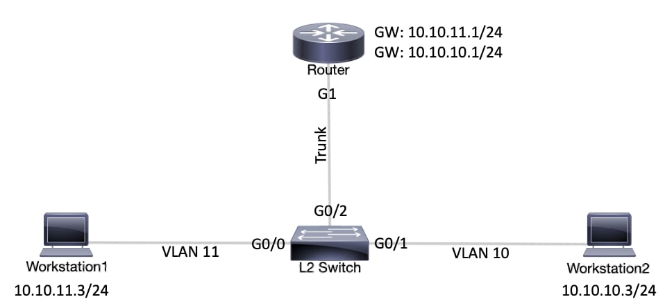
Netwerkdiagram
In dit document wordt de netwerkconfiguratie gebruikt die in dit diagram wordt weergegeven.
 NetwerkdiagramConfiguraties
| Katalysator L2 Switch |
!-- (Optional) Set the IP address and default gateway for VLAN1 for management purposes.

L2_Switch#configure terminal
Enter configuration commands, one per line.  End with CNTL/Z.
L2_Switch(config)#interface vlan 1
L2_Switch(config-if)#ip address 10.10.0.2 255.255.255.0
L2_Switch(config-if)#no ip directed-broadcast
L2_Switch(config-if)#no ip route-cache
L2_Switch(config-if)#exit
L2_Switch(config-if)#ip default-gateway 10.10.0.1

!-- (Optional) Set the VTP Mode. In our example, we have set the mode to be transparent.
!-- Depending on your network, set the VTP Mode accordingly.

L2_Switch(config)#vtp mode transparent
Setting device to VTP Transparent mode for VLANS.
L2_Switch(config)#

!-- Adding VLAN10 and VLAN11.

L2_Switch(config)#vlan 10-11
L2_Switch(config-vlan)#exit
L2_Switch(config)#

!-- Enable trunking on the interface GigabitEthernet 0/2.
!-- Enter the trunking encapsulation as dot1q.

L2_Switch(config)#interface gigabitEthernet 0/2
L2_Switch(config-if)#switchport trunk encapsulation dot1q
L2_Switch(config-if)#switchport mode trunk

!-- In case of dot1q, you need to make sure that the native VLAN matches across the link.
!-- On Catalyst Switches, by default, the native VLAN is 1.
!-- It is very important that you change the native VLAN on the router accordingly.

!-- The following set of commands can place on the interfaces connecting to the workstations.

L2_Switch(config)#interface gigabitEthernet 0/0
L2_Switch(config-if)#switchport mode access
L2_Switch(config-if)#switchport access vlan 11
L2_Switch(config-if)#exit

L2_Switch(config)#interface gigabitEthernet 0/1
L2_Switch(config-if)#switchport mode access
L2_Switch(config-if)#switchport access vlan 10
L2_Switch(config-if)#exit

!-- Remember to save the configuration.

L2_Switch#write memory
Building configuration...
|
| Router |
|
Opmerking: De volgende schermafbeeldingen tonen de opdrachten die zijn ingevoerd op de Cisco Router. Opmerkingen tussen de opdrachten worden cursief toegevoegd om bepaalde opdrachten en stappen uit te leggen.
Router#configure terminal
Enter configuration commands, one per line. End with CNTL/Z.

!-- Select GigabitEthernet 1 for the trunk configuration.
!-- No Layer 3 (L3) configuration is done here.

Router(config)#interface GigabitEthernet 1
Router(config-if)#no shut
Router(config-if)#exit

!-- Enable dot1q on the sub-interface one for each VLAN.
!-- Configure L3 information on the sub-interface for each gateway.

Router(config)#interface gigabitEthernet 1.10
Router(config-subif)#encapsulation dot1Q 10
Router(config-subif)#ip address 10.10.10.1 255.255.255.0
Router(config-subif)#exit

Router(config)#interface gigabitEthernet 1.11
Router(config-subif)#encapsulation dot1Q 11
Router(config-subif)#ip address 10.10.11.1 255.255.255.0
Router(config-subif)#exit

!-- (Optional) For the management VLAN 1 make sure that the native VLAN matches across the link.
!-- On the switch, by default, the native VLAN is 1.
!-- On the router, configure VLAN1 as the native VLAN.

Router(config)#interface gigabitEthernet 1.1
Router(config-subif)#encapsulation dot1Q 1 native
Router(config-subif)#ip address 10.10.0.1 255.255.255.0
Router(config-subif)#end

!-- Remember to save the configuration.

Router#write memory
Building configuration...
[OK]
Router#
Opmerking: De standaardgateways op de werkstations moeten correct zijn ingesteld om deze configuratie te laten werken en te kunnen pingen tussen werkstation1 en werkstation2. Voor werkstation 1 moet de standaardgateway 10.10.11.1 zijn en voor werkstation 2 moet de standaardgateway 10.10.10.1 zijn.
|
Nuttige opdrachten
Dit gedeelte helpt u te bevestigen dat uw configuratie werkt zoals verwacht.
Op de Catalyst-switch kunt u de volgende opdrachten gebruiken om te helpen bij de verificatie:
Gebruik op de Cisco Router de volgende opdrachten:
-
show ip route
-
show interface
Voorbeeld opdrachtuitvoer
katalysator-Switch
De volgende opdracht wordt gebruikt om de administratieve en operationele status van de poort te controleren. Daarnaast wordt er met deze opdracht voor gezorgd dat het native VLAN aan beide zijden van de trunk overeenkomt. Het native VLAN wordt gebruikt voor verkeer zonder tags wanneer de poort zich in de modus voor 802.1Q-trunking bevindt.
Voor 802.1Q-trunking wordt met de opdracht Uitvoer het volgende weergegeven:
L2_Switch#show interfaces gigabitEthernet 0/2 switchport
Name: Gi0/2
Switchport: Enabled
Administrative Mode: trunk
Operational Mode: trunk
Administrative Trunking Encapsulation: dot1q
Operational Trunking Encapsulation: dot1q
Negotiation of Trunking: On
Access Mode VLAN: 1 (default)
Trunking Native Mode VLAN: 1 (default)
Administrative Native VLAN tagging: enabled
Voice VLAN: none
Administrative private-vlan host-association: none
Administrative private-vlan mapping: none
Administrative private-vlan trunk native VLAN: none
Administrative private-vlan trunk Native VLAN tagging: enabled
Administrative private-vlan trunk encapsulation: dot1q
Administrative private-vlan trunk normal VLANs: none
Administrative private-vlan trunk associations: none
Administrative private-vlan trunk mappings: none
Operational private-vlan: none
Trunking VLANs Enabled: ALL
Pruning VLANs Enabled: 2-1001
Capture Mode Disabled
Capture VLANs Allowed: ALL

Protected: false
Appliance trust: none
De volgende opdracht wordt gebruikt om te controleren of de interfaces (poorten) behoren tot het juiste VLAN. In dit voorbeeld behoort interface Gi0/1 tot VLAN10 en behoort Gi0/0 tot VLAN11. De rest is lid van VLAN1.
L2_Switch#show vlan brief

VLAN Name                             Status    Ports
---- -------------------------------- --------- -------------------------------
1    default                          active    Gi0/3
10   VLAN0010                         active    Gi0/1
11   VLAN0011                         active    Gi0/0
1002 fddi-default                     act/unsup
1003 token-ring-default               act/unsup
1004 fddinet-default                  act/unsup
1005 trnet-default                    act/unsup
L2_Switch#
De volgende opdracht wordt gebruikt om de VLAN-trunkingprotocolconfiguratie (VTP) op de switch te controleren. In dit voorbeeld wordt de transparante modus gebruikt. De juiste VTP-modus is afhankelijk van de topologie van uw netwerk.
L2_Switch#show vtp status
VTP Version capable             : 1 to 3
VTP version running             : 1
VTP Domain Name                 :
VTP Pruning Mode                : Disabled
VTP Traps Generation            : Disabled
Device ID                       : 5254.0000.8000
Configuration last modified by 0.0.0.0 at 3-1-24 15:21:18

Feature VLAN:
--------------
VTP Operating Mode                : Transparent
Maximum VLANs supported locally   : 1005
Number of existing VLANs          : 7
Configuration Revision            : 0
MD5 digest                        : 0x9F 0x7D 0x8D 0x10 0xB1 0x22 0x2F 0xE7
                                    0x29 0x77 0x42 0xA7 0x95 0xE7 0x68 0x1C
Cisco-router
De volgende opdracht vertelt de L3-routeringsinformatie over de subinterfaces die op de router zijn geconfigureerd.
Router#show ip route
Codes: L - local, C - connected, S - static, R - RIP, M - mobile, B - BGP
       D - EIGRP, EX - EIGRP external, O - OSPF, IA - OSPF inter area
       N1 - OSPF NSSA external type 1, N2 - OSPF NSSA external type 2
       E1 - OSPF external type 1, E2 - OSPF external type 2, m - OMP
       n - NAT, Ni - NAT inside, No - NAT outside, Nd - NAT DIA
       i - IS-IS, su - IS-IS summary, L1 - IS-IS level-1, L2 - IS-IS level-2
       ia - IS-IS inter area, * - candidate default, U - per-user static route
       H - NHRP, G - NHRP registered, g - NHRP registration summary
       o - ODR, P - periodic downloaded static route, l - LISP
       a - application route
       + - replicated route, % - next hop override, p - overrides from PfR
       & - replicated local route overrides by connected

Gateway of last resort is not set

      10.0.0.0/8 is variably subnetted, 6 subnets, 2 masks
C        10.10.0.0/24 is directly connected, GigabitEthernet1.1
L        10.10.0.1/32 is directly connected, GigabitEthernet1.1
C        10.10.10.0/24 is directly connected, GigabitEthernet1.10
L        10.10.10.1/32 is directly connected, GigabitEthernet1.10
C        10.10.11.0/24 is directly connected, GigabitEthernet1.11
L        10.10.11.1/32 is directly connected, GigabitEthernet1.11
De volgende opdracht wordt gebruikt om de administratieve en operationele status van de interface te controleren. Voor de status van de router-interface geeft de opdracht Uitvoer het volgende weer:
Router#show interfaces
GigabitEthernet1 is up, line protocol is up
  Hardware is CSR vNIC, address is 5254.0000.004d (bia 5254.0000.004d)
  MTU 1500 bytes, BW 1000000 Kbit/sec, DLY 10 usec,
     reliability 255/255, txload 1/255, rxload 1/255
  Encapsulation ARPA, loopback not set
  Keepalive set (10 sec)
  Full Duplex, 1000Mbps, link type is auto, media type is Virtual
  output flow-control is unsupported, input flow-control is unsupported
  ARP type: ARPA, ARP Timeout 04:00:00
  Last input 00:00:00, output 00:14:10, output hang never
  Last clearing of "show interface" counters never
  Input queue: 0/375/0/0 (size/max/drops/flushes); Total output drops: 0
  Queueing strategy: fifo
  Output queue: 0/40 (size/max)
  5 minute input rate 0 bits/sec, 0 packets/sec
  5 minute output rate 0 bits/sec, 0 packets/sec
     5338 packets input, 361563 bytes, 0 no buffer
     Received 0 broadcasts (0 IP multicasts)
     0 runts, 0 giants, 0 throttles
     0 input errors, 0 CRC, 0 frame, 0 overrun, 0 ignored
     0 watchdog, 0 multicast, 0 pause input
     13 packets output, 1248 bytes, 0 underruns
     Output 0 broadcasts (0 IP multicasts)
     0 output errors, 0 collisions, 2 interface resets
     57 unknown protocol drops
     0 babbles, 0 late collision, 0 deferred
     1 lost carrier, 0 no carrier, 0 pause output
     0 output buffer failures, 0 output buffers swapped out
GigabitEthernet1.1 is up, line protocol is up
  Hardware is CSR vNIC, address is 5254.0000.004d (bia 5254.0000.004d)
  Internet address is 10.10.0.1/24
  MTU 1500 bytes, BW 1000000 Kbit/sec, DLY 10 usec,
     reliability 255/255, txload 1/255, rxload 1/255
  Encapsulation 802.1Q Virtual LAN, Vlan ID  1.
  ARP type: ARPA, ARP Timeout 04:00:00
  Keepalive set (10 sec)
  Last clearing of "show interface" counters never
GigabitEthernet1.10 is up, line protocol is up
  Hardware is CSR vNIC, address is 5254.0000.004d (bia 5254.0000.004d)
  Internet address is 10.10.10.1/24
  MTU 1500 bytes, BW 1000000 Kbit/sec, DLY 10 usec,
     reliability 255/255, txload 1/255, rxload 1/255
  Encapsulation 802.1Q Virtual LAN, Vlan ID  10.
  ARP type: ARPA, ARP Timeout 04:00:00
  Keepalive set (10 sec)
  Last clearing of "show interface" counters never
GigabitEthernet1.11 is up, line protocol is up
  Hardware is CSR vNIC, address is 5254.0000.004d (bia 5254.0000.004d)
  Internet address is 10.10.11.1/24
  MTU 1500 bytes, BW 1000000 Kbit/sec, DLY 10 usec,
     reliability 255/255, txload 1/255, rxload 1/255
  Encapsulation 802.1Q Virtual LAN, Vlan ID  11.
  ARP type: ARPA, ARP Timeout 04:00:00
  Keepalive set (10 sec)
  Last clearing of "show interface" counters never
GigabitEthernet2 is administratively down, line protocol is down
  Hardware is CSR vNIC, address is 5254.0000.004e (bia 5254.0000.004e)
  MTU 1500 bytes, BW 1000000 Kbit/sec, DLY 10 usec,
     reliability 255/255, txload 1/255, rxload 1/255
  Encapsulation ARPA, loopback not set
  Keepalive set (10 sec)
  Full Duplex, 1000Mbps, link type is auto, media type is Virtual
  output flow-control is unsupported, input flow-control is unsupported
  ARP type: ARPA, ARP Timeout 04:00:00
  Last input never, output never, output hang never
  Last clearing of "show interface" counters never
  Input queue: 0/375/0/0 (size/max/drops/flushes); Total output drops: 0
  Queueing strategy: fifo
Gerelateerde informatie
 Feedback