Configurazione di VPLS tra Cat9500 e ISR4K

Opzioni per il download
Linguaggio senza pregiudizi
La documentazione per questo prodotto è stata redatta cercando di utilizzare un linguaggio senza pregiudizi. Ai fini di questa documentazione, per linguaggio senza di pregiudizi si intende un linguaggio che non implica discriminazioni basate su età, disabilità, genere, identità razziale, identità etnica, orientamento sessuale, status socioeconomico e intersezionalità. Le eventuali eccezioni possono dipendere dal linguaggio codificato nelle interfacce utente del software del prodotto, dal linguaggio utilizzato nella documentazione RFP o dal linguaggio utilizzato in prodotti di terze parti a cui si fa riferimento. Scopri di più sul modo in cui Cisco utilizza il linguaggio inclusivo.
Informazioni su questa traduzione
Cisco ha tradotto questo documento utilizzando una combinazione di tecnologie automatiche e umane per offrire ai nostri utenti in tutto il mondo contenuti di supporto nella propria lingua. Si noti che anche la migliore traduzione automatica non sarà mai accurata come quella fornita da un traduttore professionista. Cisco Systems, Inc. non si assume alcuna responsabilità per l’accuratezza di queste traduzioni e consiglia di consultare sempre il documento originale in inglese (disponibile al link fornito).
Sommario
Introduzione
VPLS è una tecnologia di estensione di layer 2 che la maggior parte dei clienti usa con i provider di servizi Internet (ISP) e i servizi presi in prestito da terze parti. L'utilizzo di VPLS va oltre l'ambito di questa guida alla configurazione. Questa è una guida alla configurazione di base per aiutare i clienti a configurare L2VPN tra le piattaforme ISR4K esistenti e i nuovi switch Cat9500.
Prerequisiti
È necessario conoscere i concetti di base di L2VPN e configurare i modelli di pseudofili per la configurazione dei contesti di VFI L2
Requisiti
Router ISR4K (qualsiasi ISR4400/ISR4300), switch Cat9500 e due dispositivi utilizzati come dispositivi CE
Componenti usati
ISR 4451-X
C9500-40X-A
CISCO 1921
CISCO 2911
Configurazione
La configurazione indica l'utilizzo del contesto VPLS e i dettagli/tipi di VC supportati
Esempio di rete
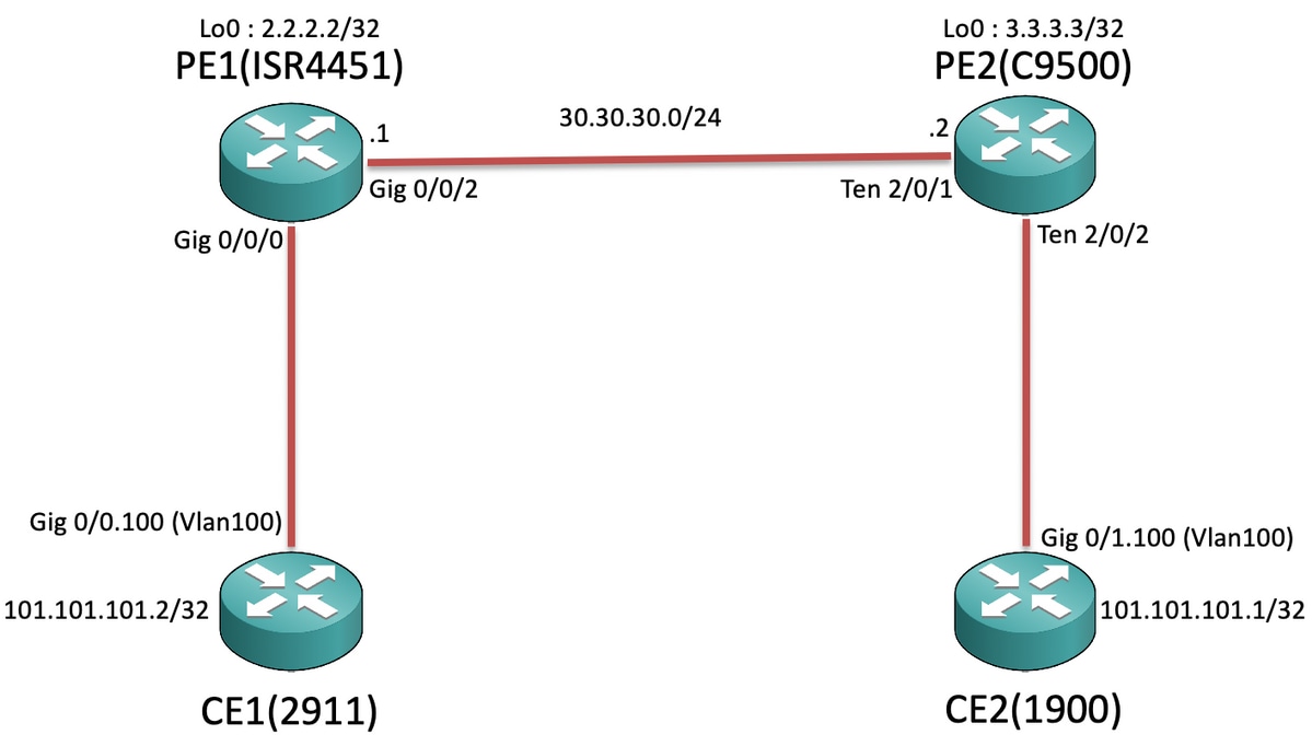
Configurazioni
Su CE1 e CE2 :
CE1#sh run Building configuration... Current configuration : 105 bytes ! interface GigabitEthernet0/0 no ip address duplex auto speed auto ! interface GigabitEthernet0/0.100 encapsulation dot1Q 100 ip address 101.101.101.2 255.255.255.0 ! |
CE2#sh run Building configuration... Current configuration : 1718 bytes ! interface GigabitEthernet0/1 no ip address duplex auto speed auto ! interface GigabitEthernet0/1.100 encapsulation dot1Q 100 ip address 101.101.101.1 255.255.255.0 ! |
In PE1 e PE2:
PE1#sh run Building configuration... Current configuration : 5049 bytes ! pseudowire-class VPLS100 encapsulation mpls no control-word ! l2 vfi 100 manual vpn id 100 bridge-domain 100 mtu 9180 neighbor 3.3.3.3 pw-class VPLS100 ! interface Loopback0 ip address 2.2.2.2 255.255.255.255 ! interface GigabitEthernet0/0/0 mtu 9180 no ip address negotiation auto service instance 100 ethernet encapsulation dot1q 100 rewrite ingress tag pop 1 symmetric bridge-domain 100 ! ! interface GigabitEthernet0/0/2 ip address 30.30.30.1 255.255.255.0 negotiation auto mpls ip ! ip route 3.3.3.3 255.255.255.255 30.30.30.2 ! mpls ldp router-id Loopback0 force ! |
PE2#sh run Building configuration... Current configuration : 10722 bytes ! ip routing ! pseudowire-class VPLS100 encapsulation mpls no control-word ! l2 vfi 100 manual vpn id 100 neighbor 2.2.2.2 pw-class VPLS100 ! interface Loopback0 ip address 3.3.3.3 255.255.255.255 ! interface TenGigabitEthernet2/0/1 no switchport ip address 30.30.30.2 255.255.255.0 mpls ip ! interface TenGigabitEthernet2/0/2 switchport trunk allowed vlan 100 switchport mode trunk ! interface Vlan100 no ip address xconnect vfi 100 ! ip route 2.2.2.2 255.255.255.255 30.30.30.1 ! mpls ldp router-id Loopback0 force ! |

Nota: Sui dispositivi ISR4K e ASR1000 in esecuzione sulle istanze del servizio EFP (Ethernet Flow Point), accertarsi di configurare il comando "rewrite in entrata tag pop 1 symmetric" nel rispettivo SI (Service Instance) in cui si desidera estendere la subnet/broadcast-domain, in modo che ISR4K/ASR1k sia in grado di ricevere i pacchetti con tag (802.1Q Vlan Tag) inviati dall'estremità CE.
Verifica
Le piattaforme Cat9500 supportano l'internetworking con "ethernet" finora in VPLS. Verificare innanzitutto che il tipo di VC sia ethernet (impostazione predefinita):
PE1#show mpls l2transport binding
  Destination Address: 3.3.3.3,VC ID: 100
    Local Label:  19
        Cbit: 0,    VC Type: Ethernet,    GroupID: n/a
        MTU: 9180,   Interface Desc: n/a
        VCCV: CC Type: RA [2], TTL [3]
              CV Type: LSPV [2]
    Remote Label: 17
        Cbit: 0,    VC Type: Ethernet,    GroupID: 0
        MTU: 9180,   Interface Desc: n/a
        VCCV: CC Type: RA [2], TTL [3]
              CV Type: LSPV [2]
PE2#show mpls l2transport binding
  Destination Address: 2.2.2.2,VC ID: 100
    Local Label:  17
        Cbit: 0,    VC Type: Ethernet,    GroupID: n/a
        MTU: 9180,   Interface Desc: n/a
        VCCV: CC Type: RA [2], TTL [3]
              CV Type: LSPV [2]
    Remote Label: 19
        Cbit: 0,    VC Type: Ethernet,    GroupID: 0
        MTU: 9180,   Interface Desc: n/a
        VCCV: CC Type: RA [2], TTL [3]
              CV Type: LSPV [2]
Il resto dei comandi sarebbe simile al modo in cui si verifica la VPN da L2VPN. Tuttavia, è importante capire che la Cat9500 ha una MTU di sistema e non è possibile modificare i valori MTU della singola interfaccia verso il lato LAN. Pertanto, è necessario configurare esplicitamente "mtu <>" nel contesto vfi l2 sulla piattaforma ISR4K in modo che i valori MTU vengano negoziati in base alla mtu del sistema configurata sullo switch Cat9500:
PE2:
PE2#show system mtu
Global Ethernet MTU is 9180 bytes.
PE1:
PE1#show mpls l2transport vc detail
Local interface: VFI 100 vfi up
  Interworking type is Ethernet
  Destination address: 3.3.3.3, VC ID: 100, VC status: up
    Output interface: Gi0/0/2, imposed label stack {17}
    Preferred path: not configured
    Default path: active
    Next hop: 30.30.30.2
  Create time: 00:02:10, last status change time: 00:02:10
    Last label FSM state change time: 00:02:10
  Signaling protocol: LDP, peer 3.3.3.3:0 up
    Targeted Hello: 2.2.2.2(LDP Id) -> 3.3.3.3, LDP is UP
    Graceful restart: not configured and not enabled
    Non stop routing: not configured and not enabled
    Status TLV support (local/remote)   : enabled/supported
      LDP route watch                   : enabled
      Label/status state machine        : established, LruRru
      Last local dataplane   status rcvd: No fault
      Last BFD dataplane     status rcvd: Not sent
      Last BFD peer monitor  status rcvd: No fault
      Last local AC  circuit status rcvd: No fault
      Last local AC  circuit status sent: No fault
      Last local PW i/f circ status rcvd: No fault
      Last local LDP TLV     status sent: No fault
      Last remote LDP TLV    status rcvd: No fault
      Last remote LDP ADJ    status rcvd: No fault
    MPLS VC labels: local 19, remote 17
    Group ID: local n/a, remote 0
    MTU: local 9180, remote 9180
    Remote interface description:
  Sequencing: receive disabled, send disabled
  Control Word: Off
  SSO Descriptor: 3.3.3.3/100, local label: 19
  Dataplane:
    SSM segment/switch IDs: 8387/4289 (used), PWID: 4
  VC statistics:
    transit packet totals: receive 0, send 0
    transit byte totals:   receive 0, send 0
    transit packet drops:  receive 0, seq error 0, send 0
PE2:
PE2#show mpls l2transport vc detail
Local interface: VFI 100 vfi up
  Interworking type is Ethernet
  Destination address: 2.2.2.2, VC ID: 100, VC status: up
    Output interface: Te2/0/1, imposed label stack {19}
    Preferred path: not configured
    Default path: active
    Next hop: 30.30.30.1
  Create time: 01:02:03, last status change time: 00:03:09
    Last label FSM state change time: 00:03:09
  Signaling protocol: LDP, peer 2.2.2.2:0 up
    Targeted Hello: 3.3.3.3(LDP Id) -> 2.2.2.2, LDP is UP
    Graceful restart: not configured and not enabled
    Non stop routing: not configured and not enabled
    Status TLV support (local/remote)   : enabled/supported
      LDP route watch                   : enabled
      Label/status state machine        : established, LruRru
      Last local dataplane   status rcvd: No fault
      Last BFD dataplane     status rcvd: Not sent
      Last BFD peer monitor  status rcvd: No fault
      Last local AC  circuit status rcvd: No fault
      Last local AC  circuit status sent: No fault
      Last local PW i/f circ status rcvd: No fault
      Last local LDP TLV     status sent: No fault
      Last remote LDP TLV    status rcvd: No fault
      Last remote LDP ADJ    status rcvd: No fault
    MPLS VC labels: local 17, remote 19
    Group ID: local n/a, remote 0
    MTU: local 9180, remote 9180
    Remote interface description:
  Sequencing: receive disabled, send disabled
  Control Word: Off
  SSO Descriptor: 2.2.2.2/100, local label: 17
  Dataplane:
    SSM segment/switch IDs: 12297/8194 (used), PWID: 1
  VC statistics:
    transit packet totals: receive 0, send 0
    transit byte totals:   receive 0, send 0
    transit packet drops:  receive 0, seq error 0, send 0
Ora, quando proviamo ad avviare i ping tra CE1 e CE2:
CE1#ping 101.101.101.1 source 101.101.101.2
Type escape sequence to abort.
Sending 5, 100-byte ICMP Echos to 101.101.101.1, timeout is 2 seconds:
Packet sent with a source address of 101.101.101.2
!!!!!
Success rate is 100 percent (5/5), round-trip min/avg/max = 1/1/4 ms
Poi, quando controlliamo le statistiche della VC per accertarci che i pacchetti stiano andando via VPLS :
PE1:
PE1#show mpls l2transport vc detail | sec statistics
  VC statistics:
    transit packet totals: receive 5, send 5
    transit byte totals:   receive 660, send 660
    transit packet drops:  receive 0, seq error 0, send 0
PE2:
PE2#show mpls l2transport vc detail | sec statistics
  VC statistics:
    transit packet totals: receive 5, send 5
    transit byte totals:   receive 680, send 680
    transit packet drops:  receive 0, seq error 0, send 0
Risoluzione dei problemi
Questo documento ha lo scopo di evidenziare i problemi di compatibilità durante la configurazione di una VPLS VC tra i router ISR/ASR e gli switch Cat9500 che agiscono come nodi PE, quindi al momento non è necessario eseguire alcuna procedura di risoluzione dei problemi.
Contributo dei tecnici Cisco
- Vipin VargheseCisco TAC
 Feedback