Spécifications port AUI Ethernet, broches et câble
Table des matières
Introduction
Ce document explique le port Ethernet AUI, les spécifications de câblage et les sorties de port.
Conditions préalables
Exigences
Aucune exigence spécifique n'est associée à ce document.
Composants utilisés
Les informations de ce document sont basées sur les versions de logiciel et matériel suivantes :
-
Câble adaptateur AUI : CAB-3CE18=
The information in this document was created from the devices in a specific lab environment. All of the devices used in this document started with a cleared (default) configuration. If your network is live, make sure that you understand the potential impact of any command.
Conventions
Pour plus d'informations sur les conventions utilisées dans ce document, consultez Conventions relatives aux conseils techniques Cisco.
Informations générales
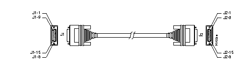
Pour plus de flexibilité, certains routeurs Cisco fournissent un connecteur AUI générique pour les ports Ethernet. Ces ports AUI sont conçus pour être connectés à un émetteur-récepteur externe en vue d'une conversion vers un type de support spécifique (paire torsadée, câble coaxial ou fibre). L'émetteur-récepteur peut être connecté directement au port AUI ou via un câble AUI, comme illustré ci-dessous :
Spécifications du câble
Cette section décrit les spécifications du port Ethernet et du câble.
Brochage du port Ethernet (AUI) (DB-15)
Le tableau ci-dessous répertorie les différentes broches et leurs signaux appropriés.
| Broche1 | Circuit Ethernet | Signal |
|---|---|---|
| 3 | PERSONNE INTÉRESSÉE | Données sortantes Circuit A |
| 10 | INTENSITÉ NUTRITIONNELLE | Données sortantes Circuit B |
| 11 | FAIRE-S | Protection de circuit de sortie de données |
| 5 | DI-A | Données Dans Le Circuit A |
| 12 | DI-B | Données Dans Le Circuit B |
| 4 | DI-S | Données dans le bouclier de circuit |
| 2 | IC-A | Commande Dans Le Circuit A |
| 9 | E122 | Commande Dans Le Circuit B |
| 1 | CI-S | Commande Dans Le Bouclier Du Circuit |
| 6 | circuit virtuel | Tension commune |
| 13 | Vice-président | Tension Plus |
| 14 | VS | Bouclier de tension (L25 et M25) |
| Coquille | PG | Terre De Protection |
1Aucune broche non référencée n'est connectée.
Caractéristiques physiques d'Ethernet version 2 et d'IEEE 802.3
Le tableau ci-dessous répertorie les caractéristiques physiques Ethernet version 2 et IEEE 802.3 du câble Ethernet.
| Ethernet | IEEE 802.3 | |||
|---|---|---|---|---|
| 10Base5 | 10Base2 | 10BaseT | ||
| Débit de données (Mbits/s) | 10 | 10 | 10 | 10 |
| Méthode de signalisation | Bande De Base | Bande De Base | Bande De Base | Bande De Base |
| Longueur de segment maximale (en mètres) | 500 | 500 | 185 | 100 (paire torsadée non blindée - UTP) |
| médias | Câble coaxial 50 ohms (épais) | Câble coaxial 50 ohms (épais) | Câble coaxial 50 ohms (mince) | UTP |
| Topologie | Autobus | Autobus | Autobus | Étoile |
Limites de connexion Ethernet de type coaxial pour transmission 10 Mbits/s
Le tableau suivant répertorie les limites de connexion Ethernet de type coaxial pour la transmission 10 Mbits/s.
| Paramètre | 10Base5 | 10Base2 |
|---|---|---|
| Diamètre du câble | 1 cm (0,4 po) | 0,6 cm (0,25 po) |
| Longueur de segment maximale | 500 m (1640 pi) | 152 m (500 pi) |
| Longueur maximale du réseau (avec quatre répéteurs) | 2500 m (8200 pi) | 762 m (2500 pi) |
| Nombre maximal de connexions (prises par segment) | 100 | 30 |
| Espacement minimum de connexion (tap) | 2.5 m (8.2 pi) | 0.5 m (1.64 pi) |
Informations connexes
Historique de révision
| Révision | Date de publication | Commentaires |
|---|---|---|
1.0 |
18-Nov-2003
|
Première publication |
 Commentaires
Contacter Cisco
- Ouvrir un dossier d’assistance

- (Un contrat de service de Cisco est requis)