Resolución de Problemas de Servicio de LAN Privada Virtual VPN de Capa 2 en IOS XE
Contenido
Introducción
Este documento describe cómo resolver problemas del Servicio de LAN privada virtual (VPLS) VPN de Capa 2 en Tecnologías para Cisco IOS® XE.
Prerequisites
Requirements
Cisco recomienda que tenga conocimiento sobre estos temas:
- Routing IP básico
- Servicio de LAN privada virtual VPN de capa 2
Componentes Utilizados
La información de este documento se basa en el software Cisco IOS XE.
La información que contiene este documento se creó a partir de los dispositivos en un ambiente de laboratorio específico. Todos los dispositivos que se utilizan en este documento se pusieron en funcionamiento con una configuración verificada (predeterminada). Si tiene una red en vivo, asegúrese de entender el posible impacto de cualquier comando.
Diagrama de la red
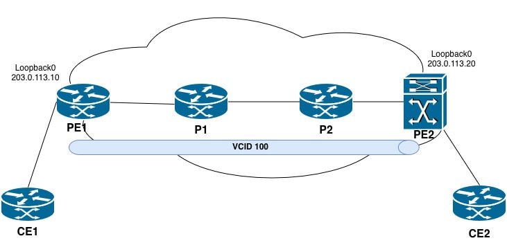 Topología VPLS
La conexión cruzada VPLS no está operativa
Pasos para la resolución de problemas
La conexión cruzada VPLS se encuentra en estado inactivo después de que la sesión se haya terminado inesperadamente.
PE2#show xconnect all
Legend: XC ST=Xconnect State S1=Segment1 State S2=Segment2 State
UP=Up DN=Down AD=Admin Down IA=Inactive
SB=Standby HS=Hot Standby RV=Recovering NH=No Hardware

XC ST  Segment 1                         S1 Segment 2                         S2
------+---------------------------------+--+---------------------------------+--
DN pri vfi 100                           UP mpls 203.0.113.10:100             DN
UP pri ac Vl100:100(Eth VLAN)            UP vfi 100                           UP
UP pri bd 100                            UP vfi 100                           UP
Paso 1. Confirme el estado exacto de VC/VPLS.
PE2#show mpls l2transport vc 100 detail
Local interface: VFI 100 vfi up
   Interworking type is Ethernet
   Destination address: 203.0.113.10, VC ID: 100, VC status: down
     Last error: Local access circuit is not ready for label advertise << The local device is unable to advertise labels because the access circuit (AC) is not in a ready state.
     Output interface: none, imposed label stack {} << no MPLS labels are being imposed because no path exists.
     Preferred path: not configured << No explicit traffic engineering path is configured for this pseudowire.
     Default path: no route << No route to the remote PE (203.0.113.10) exists in the routing table.
     No adjacency
Create time: 10:50:35, last status change time: 00:17:39
  Last label FSM state change time: 00:17:33
Signaling protocol: LDP, peer x.x.x.x:0 up
  Targeted Hello: 203.0.113.20(LDP Id) -> 203.0.113.10, LDP is DOWN, no binding
  Graceful restart: not configured and not enabled
  Non stop routing: not configured and not enabled
  Status TLV support (local/remote) : enabled/None (no remote binding
    LDP route watch : enabled
    Label/status state machine : local ready, LruRnd
    Last local dataplane status rcvd: No fault
    Last BFD dataplane status rcvd: Not sent
    Last BFD peer monitor status rcvd: No fault
    Last local AC circuit status rcvd: No fault
    Last local AC circuit status sent: DOWN(hard-down) << The local device is advertising the access circuit as hard-down to the remote PE.
    Last local PW i/f circ status rcvd: No fault
    Last local LDP TLV status sent: No fault
    Last remote LDP TLV status rcvd: None (no remote binding) << No status has been received from the remote PE.
    Last remote LDP ADJ status rcvd: None (no remote binding) << No adjacency status received from the remote peer.
  MPLS VC labels: local 16, remote unassigned
  Group ID: local n/a, remote unknown
  MTU: local 1500, remote unknown
  Remote interface description:
Sequencing: receive disabled, send disabled
Control Word: On (configured: autosense)
SSO Descriptor: 203.0.113.10/100, local label: 16
Dataplane:
  SSM segment/switch IDs: 0/8194 (used), PWID: 1
VC statistics:
  transit packet totals: receive 0, send 0
  transit byte totals: receive 0, send 0
  transit packet drops: receive 0, seq error 0, send 0
La conexión cruzada VPLS (VC ID 100) ha pasado a un estado inactivo. La causa principal se atribuye a las condiciones descritas:
1. Sin ruta al PE remoto - El router no tiene una ruta a 203.0.113.10 en la tabla de ruteo (trayectoria predeterminada: sin ruta). Sin una ruta válida, no se puede establecer ninguna ruta conmutada por etiquetas (LSP) MPLS.
2. La sesión LDP objetivo ha caído - La sesión LDP objetivo de 203.0.113.20 a 203.0.113.10 no está establecida. Esto evita el intercambio de etiquetas de pseudowire entre los routers PE.
3. Sin vinculación de etiquetas remotas: debido a que la sesión LDP de destino está inactiva, no se ha asignado ninguna etiqueta remota para VC 100. El pseudowire no puede reenviar tráfico sin etiquetas locales y remotas.
4. Sin adyacencia - Sin una ruta válida y una sesión LDP, no existe adyacencia MPLS hacia el PE remoto.
Paso 2. Compruebe el circuito de conexión local.
En el PE donde el VC está inactivo:
PE2#show interfaces vlan 100 | include up|errors
Vlan100 is up, line protocol is up , Autostate Disabled
Keepalive not supported
0 input errors, 0 CRC, 0 frame, 0 overrun, 0 ignored
0 output errors, 1 interface resets

PE2#show running-config interface vlan 100
Building configuration...

Current configuration : 72 bytes
!
interface Vlan100
no ip address
no autostate
xconnect vfi 100
end
Paso 3. Verifique la configuración de VFI.
PE2#show running-config | section l2 vfi
l2 vfi 100 manual
vpn id 100
neighbor 203.0.113.10 pw-class VPLS_100

PE2#show l2vpn vfi
Legend: RT=Route-target, S=Split-horizon, Y=Yes, N=No

VFI name: 100, state: up, type: multipoint, signaling: LDP
  VPN ID: 100
  Bridge-Domain 100 attachment circuits:
    Vlan100
  Pseudo-port interface: pseudowire100001
  Interface Peer Address VC ID S
  pseudowire100002 203.0.113.10 100 Y
Observaciones clave
1. VFI funciona correctamente: la instancia de VFI local está activa y lista para reenviar tráfico.
2. El circuito de conexión está enlazado: Vlan100 está correctamente asociado con el dominio de puente 100 y el VFI.
3. Pseudowire está configurado - Un pseudowire (pseudowire100002) se define hacia el PE remoto en 203.0.113.10 con VC ID 100.
4. El horizonte dividido está habilitado: se trata de un comportamiento esperado en un entorno multipunto VPLS para evitar bucles de capa 2.
Paso 4. Verifique la disponibilidad del loopback PE:
PE2#ping 203.0.113.10
Type escape sequence to abort.
Sending 5, 100-byte ICMP Echos to 203.0.113.10, timeout is 2 seconds:
!!!!!
Success rate is 100 percent (5/5), round-trip min/avg/max = 1/1/1 ms

PE2#show ip route 203.0.113.10
Routing entry for 203.0.113.10/32
Known via "ospf 1", distance 110, metric 2, type intra area
Last update from 192.0.2.9 on TwentyFiveGigE1/0/3, 00:01:30 ago
Routing Descriptor Blocks:
* 192.0.2.9, from 198.51.100.2, 00:01:30 ago, via TwentyFiveGigE1/0/3
Route metric is 2, traffic share count is 1

PE2#ping mpls ipv4 203.0.113.10/32 source 203.0.113.20
Sending 5, 72-byte MPLS Echos to 203.0.113.10/32,
timeout is 2 seconds, send interval is 0 msec:

Codes: '!' - success, 'Q' - request not sent, '.' - timeout,
'L' - labeled output interface, 'B' - unlabeled output interface,
'D' - DS Map mismatch, 'F' - no FEC mapping, 'f' - FEC mismatch,
'M' - malformed request, 'm' - unsupported tlvs, 'N' - no label entry,
'P' - no rx intf label prot, 'p' - premature termination of LSP,
'R' - transit router, 'I' - unknown upstream index,
'l' - Label switched with FEC change, 'd' - see DDMAP for return code,
'X' - unknown return code, 'x' - return code 0

Type escape sequence to abort.
!!!!!
Success rate is 100 percent (5/5), round-trip min/avg/max = 1/1/2 ms
Total Time Elapsed 8 ms
Ping Estándar Versus MPLS LSP Ping: Distinciones clave
Un ping estándar puede tener éxito incluso cuando el MPLS LSP se rompe porque:
· El paquete ICMP puede ser ruteado por IP (no conmutado por etiquetas) si el destino es directamente alcanzable a través de IP.
· Los routers de tránsito pueden reenviar el paquete ICMP mediante la búsqueda de IP si no se impone ninguna etiqueta.
Por el contrario, ping mpls ipv4 valida el plano de datos MPLS real forzando el paquete a través de la trayectoria conmutada por etiquetas. Esto garantiza que:
· Las etiquetas se asignan y distribuyen correctamente.
· Las entradas de LFIB son consistentes en cada salto.
· La ruta de extremo a extremo de LSP es funcional.
Paso 5. Verificar MPLS y LDP en el núcleo:
PE2#show mpls ldp neighbor
    Peer LDP Ident: 203.0.113.10:0; Local LDP Ident 203.0.113.20:0
        TCP connection: 203.0.113.10.646 - 203.0.113.20.39001
        State: Oper; Msgs sent/rcvd: 16/15; Downstream
        Up time: 00:02:15
        LDP discovery sources:
          TwentyFiveGigE1/0/3, Src IP addr: 192.0.2.9
          Targeted Hello 203.0.113.20 -> 203.0.113.10, active, passive
        Addresses bound to peer LDP Ident:
          203.0.113.10 192.0.2.6 192.0.2.9
Este comando presenta la información de sesión de vecino LDP entre el router local (PE2) y el peer remoto. Cada campo de la salida se describe en detalle.
- Identificación de pares:
Sangría LDP de Peer |203.0.113.10:0 | El ID de router LDP del peer remoto. El :0 indica el espacio de etiquetas predeterminado para toda la plataforma. Suele ser la dirección de loopback del router remoto.
Identificación de LDP local |203.0.113.20:0 | El ID de router LDP del router local (PE2). Suele ser la dirección de loopback de PE2.
- Información de sesión TCP:
conexión TCP | 203.0.113.10.646 - 203.0.113.20.39001 | La sesión TCP utilizada para la comunicación LDP. El par remoto (203.0.113.10) utiliza el conocido puerto LDP 646 y el router local (203.0.113.20) utiliza el puerto efímero 39001. LDP utiliza TCP para una distribución de etiquetas confiable.
- Estado de sesión:
Estado | Oper | La sesión de LDP está en un estado operativo, lo que significa que la sesión está completamente establecida y es funcional.
Mensajes enviados/recibidos |16/15 | Número de mensajes PDL enviados (16) y recibidos (15) desde el establecimiento de la sesión. Esto incluye señales de mantenimiento, asignaciones de etiquetas y otros mensajes LDP.
Velocidad de descarga |- | Indica el modo de distribución de etiquetas. Downstream Unsolicited significa que el peer distribuye etiquetas a PE2 sin que PE2 las solicite explícitamente. Este es el modo predeterminado para LDP.
Tiempo de actividad |00:02:15 | La sesión lleva operativa 2 minutos y 15 segundos. - Fuentes de detección de LDP:
TwentyFiveGigE1/0/3 | Dirección IP de origen: 192.0.2.9 | Se recibe un saludo de detección básica (nivel de link) del par en la interfaz TwentyFiveGigE1/0/3 con una dirección IP de origen de 192.0.2.9. Esto indica que los dos routers están conectados directamente en esta interfaz.
Saludo dirigido | 203.0.113.20 → 203.0.113.10, activo, pasivo | Existe un saludo de detección dirigida (extendido) entre el router local (203.0.113.20) y el par remoto (203.0.113.10). - Direcciones Enlazadas a la Sangría LDP de Peer:
Direcciones enlazadas a pares | 203.0.113.10, 192.0.2.6, 192.0.2.9 | La lista de direcciones IP que el peer remoto ha anunciado a través de mensajes de dirección LDP. Representan las interfaces en el router remoto.
Paso 5.1 Verificación de la Trayectoria MPLS Label-Switched al Peer VPLS Remoto
PE2#show mpls forwarding-table 203.0.113.10
Local        Outgoing         Prefix               Bytes Label     Outgoing          Next Hop
Label        Label            or Tunnel Id         Switched        interface
25           Pop Label        203.0.113.10/32      0                Twe1/0/3         192.0.2.9

PE2#show mpls ldp bindings 203.0.113.10 32
  lib entry: 203.0.113.10/32, rev 69
        local binding: label: 25
        remote binding: lsr: 203.0.113.10:0, label: imp-null
PE2 recibe imp-null directamente de PE1, omitiendo la ruta de etiqueta esperada a través de P2 y P1. Esto indica que falta una sesión LDP o un problema de configuración MPLS entre PE2 y P2.
Paso 5.2 Valide la información de salto siguiente ejecutando los comandos provistos:
- show mpls ldp neighbor
- show mpls forwarding-table
P2#show mpls forwarding-table 203.0.113.10
Local        Outgoing          Prefix Bytes          Label           Outgoing       Next Hop
Label        Label             or Tunnel Id          Switched        interface
None         No Label          203.0.113.10/32       0
Observación clave
- Etiqueta local: Ninguno | P2 no ha asignado una etiqueta local para este prefijo.
- Etiqueta saliente: Sin etiqueta | No se realiza ninguna operación de etiqueta.
- Sin interfaz saliente ni salto siguiente | El prefijo se trata como propiedad local; no se produce reenvío hacia PE1.
P2#show mpls ldp neighbor
    Peer LDP Ident: 203.0.113.20:0; Local LDP Ident 198.51.100.2:0
        TCP connection: 203.0.113.20.17326 - 198.51.100.2.646
        State: Oper; Msgs sent/rcvd: 30/29; Downstream
        Up time: 00:13:57
        LDP discovery sources:
           GigabitEthernet0/0/1, Src IP addr: 192.0.2.10
        Addresses bound to peer LDP Ident:
          203.0.113.20 192.0.2.10
Peer LDP Ident: 198.51.100.1:0; Local LDP Ident 198.51.100.2:0
    TCP connection: 198.51.100.1.646 - 198.51.100.2.12799
    State: Oper; Msgs sent/rcvd: 30/28; Downstream
    Up time: 00:13:56
    LDP discovery sources:
      GigabitEthernet0/0/0, Src IP addr: 192.0.2.5
    Addresses bound to peer LDP Ident:
      192.0.2.2 192.0.2.5 198.51.100.1

P2#show ip ospf neighbor

Neighbor ID       Pri   State           Dead Time    Address           Interface
198.51.100.3        0   FULL/ -         00:00:34     192.0.2.10        GigabitEthernet0/0/1
198.51.100.1        0   FULL/ -         00:00:34     192.0.2.5         GigabitEthernet0/0/0
Observación clave
- P2 no tiene una adyacencia LDP directa con PE1 (203.0.113.10). Esto es de esperar, ya que P1 reside entre P2 y PE1 en la topología. P2 es responsable del tráfico de switching de etiquetas hacia P1, que luego lo reenvía a PE1.
- La sangría de LDP de P2 es 198.51.100.2:0 | P2 utiliza 198.51.100.2 como su ID de router LDP, no 203.0.113.10. Sin embargo, 203.0.113.10 aún está configurado en Loopback10 y causa un conflicto de ruteo.
Paso 6. Verifique la ruta a la dirección de loopback PE remota:
P2#show ip route 203.0.113.10
Routing entry for 203.0.113.10/32
  Known via "connected", distance 0, metric 0 (connected, via interface)
  Routing Descriptor Blocks:
  * directly connected, via Loopback10
      Route metric is 0, traffic share count is 1
Conclusión
- Dirección IP duplicada: la dirección IP 203.0.113.10 se configura en P2 (Loopback10) y PE1 (Loopback0), lo que crea un conflicto en el dominio MPLS.
- Conflicto de ruteo: P2 instala 203.0.113.10/32 como una ruta conectada (distancia administrativa 0), que tiene precedencia sobre cualquier ruta aprendida de IGP originada por PE1.
- Falla de LSP - Debido a que P2 considera el prefijo como propiedad local, no asigna ni anuncia una etiqueta de transporte para 203.0.113.10/32 a PE2.
- Impacto de VPLS: la ausencia de una etiqueta de transporte válida de P2 impide que PE2 establezca un LSP a PE1. Como resultado, no se puede formar la ruta de transporte de pseudowire de VPLS.
Conexión cruzada VPLS establecida pero ningún tráfico de datos atraviesa el Pseudowire
Verificación operativa de VPLS para Catalyst serie 9000
Pasos para la resolución de problemas
Paso 1. Confirme que el pseudowire está en un estado operativo.
Asegúrese de que los parámetros son correctos:
- El estado de VFI es activo
- La interfaz pseudowire aparece en la lista
- Se muestran la dirección del par y el ID de VC correctos
PE2#show mpls l2transport vc

Local intf    Local circuit              Dest address    VC ID      Status
------------- -------------------------- --------------- ---------- ----------
VFI 100        vfi                       203.0.113.10    100        UP
PE2#show mpls l2transport vc 100 detail
Local interface: VFI 100 vfi up
  Interworking type is Ethernet
  Destination address: 203.0.113.10, VC ID: 100, VC status: up
    Output interface: Twe1/0/3, imposed label stack {17 16}
    Preferred path: not configured
    Default path: active
    Next hop: 192.0.2.9
Create time: 1d11h, last status change time: 00:30:50
  Last label FSM state change time: 00:30:26
Signaling protocol: LDP, peer 203.0.113.10:0 up
  Targeted Hello: 203.0.113.20(LDP Id) -> 203.0.113.10, LDP is UP
  Graceful restart: not configured and not enabled
  Non stop routing: not configured and not enabled
  Status TLV support (local/remote) : enabled/supported
    LDP route watch : enabled
    Label/status state machine : established, LruRru
    Last local dataplane status rcvd: No fault
    Last BFD dataplane status rcvd: Not sent
    Last BFD peer monitor status rcvd: No fault
    Last local AC circuit status rcvd: No fault
    Last local AC circuit status sent: No fault
    Last local PW i/f circ status rcvd: No fault
    Last local LDP TLV status sent: No fault
    Last remote LDP TLV status rcvd: No fault
    Last remote LDP ADJ status rcvd: No fault
  MPLS VC labels: local 16, remote 16
  Group ID: local n/a, remote 0
  MTU: local 1500, remote 1500
  Remote interface description:
  MAC Withdraw: sent:1, received:0
Sequencing: receive disabled, send disabled
Control Word: On (configured: autosense)
SSO Descriptor: 203.0.113.10/100, local label: 16
Dataplane:
  SSM segment/switch IDs: 16395/8194 (used), PWID: 1
VC statistics:
transit packet totals: receive 0, send 0
transit byte totals: receive 0, send 0
transit packet drops: receive 0, seq error 0, send 0
- estado de VFI | up | El VFI funciona correctamente en el dispositivo local.
- Dirección de destino |203.0.113.10 | El ID del router PE remoto (dirección de bucle invertido PE1).
- ID de VC | 100 | El identificador de circuito virtual para este pseudowire. Debe coincidir en ambos routers PE.
- estado de VC | up | El pseudowire está operativo. Tanto la señalización local como remota indican que no hay fallas.
- Pila de etiquetas impuesta {17 16} | La pila MPLS de dos etiquetas impuesta a los paquetes que entran en el pseudowire. La etiqueta 17 es la etiqueta de transporte (externa) utilizada para alcanzar el PE remoto a través del núcleo MPLS. La etiqueta 16 es la etiqueta del VC (interna) utilizada para identificar el pseudowire en el PE remoto.
- Saludo dirigido | 203.0.113.20 → 203.0.113.10, LDP es UP | La sesión LDP objetivo entre PE2 (local) y PE1 (remoto) está establecida y en funcionamiento.
- Etiqueta local | 16 | La etiqueta VC asignada por PE2 para este pseudowire. El PE remoto (PE1) utiliza esta etiqueta cuando envía tráfico a PE2. Etiqueta remota | 16 | La etiqueta VC anunciada por PE1 para este pseudowire. PE2 impone esta etiqueta (etiqueta interna) al enviar tráfico a PE1.
- Retirada de MAC enviada | 1 | PE2 ha enviado 1 mensaje de retirada de MAC al PE remoto. Se utiliza para vaciar las tablas de direcciones MAC después de un cambio de topología.
- MAC Withdraw recibido | 0 | No se ha recibido ningún mensaje de retirada de MAC desde el PE remoto.
- Estadísticas de VC | no se está reenviando tráfico en ninguna dirección (enviar: 0, recibir: 0).
Paso 2. Verifique el estado del circuito de conexión (interfaz troncal).
Confirme que la interfaz troncal esté operativa y asociada con la VLAN correcta.
Controle lo siguiente:
- La interfaz está en estado activo/activo
- La VLAN asociada con el dominio de puente VPLS está permitida y activa en el trunk
- STP no recorta ni bloquea la VLAN
PE2#show interfaces twentyFiveGigE 1/0/2 status
Port       Name        Status        Vlan          Duplex       Speed  Type
Twe1/0/2               connected     trunk           full         10G  SFP-10GBase-SR
PE2#show interfaces trunk
Port         Mode        Encapsulation   Status       Native vlan
Twe1/0/2     on          802.1q          trunking     1

Port         Vlans allowed on trunk
Twe1/0/2     100

Port         Vlans allowed and active in management domain
Twe1/0/2     100

Port         Vlans in spanning tree forwarding state and not pruned
Twe1/0/2     100
Paso 3. Verifique la asociación de vlan con el dominio de bridge.
En el Catalyst 9000 con una configuración troncal (sin EVC), la vlan se debe asignar al dominio de bridge.
Confirmar:
- La VLAN se asocia con el dominio de bridge a través de la vfi o la configuración de miembro.
- La configuración de dominio de puente hace referencia al VFI correcto.
PE2#show running-config interface vlan100
Building configuration...

Current configuration : 72 bytes
!
interface Vlan100
no ip address
xconnect vfi 100
Paso 4. Verifique el aprendizaje de la dirección MAC.
Confirme que se están aprendiendo las direcciones MAC del circuito de conexión local y del pseudowire remoto.
Controle lo siguiente:
- La dirección MAC CE1 local se aprende en la interfaz troncal.
- La dirección MAC CE2 remota se aprende en la interfaz de pseudowire.
Si no se aprende ninguna dirección MAC en el pseudowire:
- El tráfico no se recibe del PE remoto.
- El PE remoto tiene un problema de configuración que impide que el tráfico ingrese al pseudowire.
- El dominio de bridge no está correctamente asociado con la interfaz de pseudowire.
Si no se aprende ninguna dirección MAC en el troncal local:
- El dispositivo CE no transmite el tráfico en la VLAN esperada.
- La VLAN se encuentra en estado bloqueado o inactivo en la interfaz troncal.
PE2#show mac address-table vlan 100
          Mac Address Table
-------------------------------------------

Vlan Mac Address Type     Ports
---- ----------- -------- -----
100 cc7f.76b7.525f STATIC Vl100
100 e462.c4bb.17f1 DYNAMIC Twe1/0/2  >> CE2 Mac address learned over Twe1/0/2 interface.
Paso 5. Verifique el estado del protocolo de árbol de extensión (STP).
STP puede bloquear la VLAN en la interfaz trunk, lo que evita que el tráfico ingrese al dominio de bridge.
Controle lo siguiente:
· El puerto trunk está en un estado de reenvío para la VLAN asociada con el dominio de bridge VPLS
· El puerto no se encuentra en estado de bloqueo, escucha o aprendizaje
Si STP está bloqueando el puerto:
· Ajustar la prioridad STP o el costo del puerto
· Considere la posibilidad de configurar el puerto troncal como un puerto de extremo STP (si es apropiado para la topología)
PE2#show spanning-tree vlan 100

VLAN0100
  Spanning tree enabled protocol rstp
  Root ID    Priority 32868
           Address cc7f.76b7.51c0
           This bridge is the root
           Hello Time 2 sec Max Age 20 sec Forward Delay 15 sec

Bridge ID  Priority  32868 (priority 32768 sys-id-ext 100)
           Address   cc7f.76b7.51c0
           Hello Time 2 sec Max Age 20 sec Forward Delay 15 sec
           Aging Time 300 sec

Interface           Role Sts Cost      Prio.Nbr Type
------------------- ---- --- --------- -------- --------------------------------
Twe1/0/2            Desg FWD 2000      128.2    P2p
Paso 6. Verifique la pila de etiquetas MPLS y la ruta de reenvío.
Confirme que se han impuesto las etiquetas correctas y que la ruta de reenvío es válida.
Controle lo siguiente:
- Hay una etiqueta saliente válida (no Sin etiqueta ni Ninguna)
- La interfaz saliente y el siguiente salto son correctos
De PE2 a P2 LSP path:
PE2#show mpls forwarding-table 203.0.113.10 32
Local     Outgoing     Prefix            Bytes Label     Outgoing      Next Hop
Label     Label        or Tunnel Id      Switched        interface
22        17           203.0.113.10/32   810             Twe1/0/3      192.0.2.9 << For the transport path to the remote PE1 loopback, the imposed outgoing label is 17. The router at 192.0.2.9 assigned this value as its local label binding for the destination prefix.
De la trayectoria de LSP P2 a P1:
P2#show mpls forwarding-table 203.0.113.10 32
Local     Outgoing    Prefix            Bytes Label     Outgoing       Next Hop
Label     Label       or Tunnel Id      Switched        interface
17        16          203.0.113.10/32   79290           Gi0/0/0        192.0.2.5 << Local label as 17 and the imposed outgoing label is 16. The router at 192.0.2.5 assigned this value as its local label binding for the destination prefix.
De la ruta LSP P1 a PE1:
P1#show mpls forwarding-table 203.0.113.10 32
Local     Outgoing    Prefix            Bytes Label     Outgoing       Next Hop
Label     Label       or Tunnel Id      Switched        interface
16        Pop Label   203.0.113.10/32   76184           Gi0/0/0        192.0.2.1 << Pop Label is performed before forwarding the packet to the next hop. This confirms that the next hop (PE1) advertised implicit null to P1.
De la ruta LSP P1 a PE1:
PE1#show mpls forwarding-table 203.0.113.10 32
Local      Outgoing   Prefix           Bytes Label         Outgoing       Next Hop
Label      Label      or Tunnel Id     Switched            interface
None       No Label   203.0.113.10/32  0
Confirmación de ruta de etiqueta:
Basándose en esta salida y en las salidas anteriores de PE2 y P2, la ruta conmutada por etiquetas completa de PE2 a PE1 es:
[PE2] Packet leaves with label stack: | 17 | (transport label)
        ↓
[P2]  Receives label 17, swaps to 16: | 16 | (transport label)
        ↓
[P1]  Receives label 16, pops label:  | IP | (pure IP packet)
        ↓
[PE1] Receives pure IP packet - local delivery
Cuando el tráfico VPLS atraviesa este LSP, el paquete lleva una pila de dos etiquetas (transport : VC (etiqueta)
[PE2] Packet leaves with label stack: | 17 | 16 | (transport + VC label)
       ↓
[P2] Receives label 17, swaps to 16:  | 16 | 16 | (transport + VC label)
       ↓
[P1] Receives label 16, pops label:   | 16 | (VC label only)
       ↓
[PE1] Receives VC label 16 - pseudowire disposition into bridge domain
Conclusión
El LSP de transporte MPLS de PE2 a PE1 está completamente operativo y correctamente programado en todos los routers de la trayectoria. La señalización de pseudowire VPLS está completa, con etiquetas tanto locales como remotas intercambiadas y sin reportar fallas.
Sin embargo, no se reenvía tráfico de usuario a través del pseudowire a pesar de que el plano de control esté completamente establecido. Esto confirma que el problema reside fuera del núcleo MPLS y la señalización de pseudowire, específicamente en la capa del circuito de conexión en uno o ambos routers PE
Verificación operativa de VPLS para routers
Pasos para la resolución de problemas
Paso 1. Confirme el estado exacto de VC/VPLS.
Asegúrese de que los parámetros son correctos:
PE1#show mpls l2transport vc

Local intf    Local circuit              Dest address     VC ID     Status
------------- -------------------------- --------------- ---------- ----------
VFI 100        vfi                       203.0.113.20    100         UP
PE1#show mpls l2transport vc 100 detail
Local interface: VFI 100 vfi up
  Interworking type is Ethernet
  Destination address: 203.0.113.20, VC ID: 100, VC status: up
    Output interface: Te0/0/4, imposed label stack {19 16}
    Preferred path: not configured
    Default path: active
    Next hop: 192.0.2.2
  Create time: 1d09h, last status change time: 08:38:02
    Last label FSM state change time: 08:38:25
  Signaling protocol: LDP, peer 203.0.113.20:0 up
    Targeted Hello: 203.0.113.10(LDP Id) -> 203.0.113.20, LDP is UP
    Graceful restart: not configured and not enabled
    Non stop routing: not configured and not enabled
    Status TLV support (local/remote) : enabled/supported
      LDP route watch : enabled
      Label/status state machine : established, LruRru
      Last local dataplane status rcvd: No fault
      Last BFD dataplane status rcvd: Not sent
      Last BFD peer monitor status rcvd: No fault
      Last local AC circuit status rcvd: No fault
      Last local AC circuit status sent: No fault
      Last local PW i/f circ status rcvd: No fault
      Last local LDP TLV status sent: No fault
      Last remote LDP TLV status rcvd: No fault
      Last remote LDP ADJ status rcvd: No fault
    MPLS VC labels: local 16, remote 16
    Group ID: local n/a, remote 0
    MTU: local 1500, remote 1500
    Remote interface description:
    MAC Withdraw: sent:0, received:1
  Sequencing: receive disabled, send disabled
  Control Word: On (configured: autosense)
  SSO Descriptor: 203.0.113.20/100, local label: 20
  Dataplane:
    SSM segment/switch IDs: 8199/4097 (used), PWID: 1
  VC statistics:
    transit packet totals: receive 336, send 0
    transit byte totals:   receive 27552, send 0
    transit packet drops: receive 0, seq error 0, send 0
- estado de VFI | up | El VFI funciona correctamente en PE1.
- Dirección de destino |203.0.113.20 | El ID del router PE remoto (dirección de bucle invertido PE2).
- ID de VC | 100 | El identificador de circuito virtual para este pseudowire. Este valor coincide en ambos routers PE.
- estado de VC | up | El pseudowire está operativo. Tanto la señalización local como remota indican que no hay fallas.
- Interfaz local | VFI 100 | La instancia de reenvío virtual local asociada a este pseudowire.
- Pila de etiquetas impuesta | {19 16} | La pila MPLS de dos etiquetas impuesta a los paquetes que entran en el pseudowire. La etiqueta 19 es la etiqueta de transporte (externa) utilizada para alcanzar PE2 a través del núcleo MPLS. La etiqueta 16 es la etiqueta VC (interna) utilizada para identificar el pseudowire en PE2.
- Saludo dirigido | 203.0.113.10 → 203.0.113.20, LDP es UP | La sesión LDP objetivo de PE1 (local) a PE2 (remoto) está establecida y en funcionamiento.
- Etiqueta local | 16 | La etiqueta VC asignada por PE1 para este pseudowire. PE2 utiliza esta etiqueta (como etiqueta interna) cuando envía tráfico a PE1.
- Retirada de MAC enviada | 0 | PE1 no ha enviado ningún mensaje de retirada de MAC a PE2.
- MAC Withdraw recibido | 1 | PE1 ha recibido 1 mensaje de extracción de MAC de PE2. Esto indica que PE2 experimentó un cambio de topología y solicitó a PE1 que vaciara su tabla de direcciones MAC para este VFI.
- Estadísticas de VC | Paquetes de tránsito recibidos | 336 | Se han recibido 336 paquetes de PE2 en este pseudowire.
Bytes de tránsito recibidos | 27 552 | Se han recibido 27.552 bytes de PE2.
Paquetes de tránsito enviados | 0 | No se han enviado paquetes desde PE1 al pseudowire hacia PE2.
Bytes de tránsito enviados | 0 | No se han enviado bytes hacia PE2.
Paso 2. Verifique la configuración y la pertenencia al dominio de puente.
Confirme que el dominio de bridge tenga los miembros correctos (interfaz de instancia de servicio y pseudowire).
PE1#show running-config interface TenGigabitEthernet0/0/5
Building configuration...

Current configuration : 174 bytes
!
interface TenGigabitEthernet0/0/5
no ip address
service instance 100 ethernet
encapsulation dot1q 100
rewrite ingress tag pop 1 symmetric
bridge-domain 100
!
end

PE1#show interfaces tenGigabitEthernet 0/0/5 | include up|errors
TenGigabitEthernet0/0/5 is up, line protocol is up
  Keepalive not supported
  Full Duplex, 10000Mbps, link type is force-up, media type is H10GB-CU1M
     0 input errors, 0 CRC, 0 frame, 0 overrun, 0 ignored
     0 output errors, 0 collisions, 1 interface resets
Paso 3. Verifique el aprendizaje de la dirección MAC.
Confirme que se están aprendiendo las direcciones MAC del circuito de conexión local y del pseudowire remoto.
PE1#show bridge-domain
Bridge-domain 100 (2 ports in all)
State: UP                 Mac learning: Enabled
Aging-Timer: 300 second(s)
Unknown Unicast Flooding Suppression: Disabled
Maximum address limit: 65536
    TenGigabitEthernet0/0/5 service instance 100
    vfi 100 neighbor 203.0.113.20 100
   AED MAC address Policy Tag Age Pseudoport
-----------------------------------------------------------------------------
El dominio de bridge en sí está activo, pero la ausencia de direcciones MAC aprendidas es el detalle clave. Por lo general, esto apunta a que aún no se ha detectado tráfico o a un problema de mapeo/reenvío de servicios en algún lugar entre la interfaz local, el dominio de bridge y el VFI remoto.
Paso 4. Verifique la configuración de VFI:
PE1#show running-config | section vfi
l2 vfi 100 manual
 vpn id 100
 bridge-domain 100
neighbor 203.0.113.20 encapsulation mpls
Paso 5. Verifique la trayectoria de transporte MPLS.
Realice una validación rápida enviando un traceroute MPLS a la dirección de loopback remota.
PE1#traceroute mpls ipv4 203.0.113.20 255.255.255.255 source 203.0.113.10
Tracing MPLS Label Switched Path to 203.0.113.20/32, timeout is 2 seconds

Codes: '!' - success, 'Q' - request not sent, '.' - timeout,
'L' - labeled output interface, 'B' - unlabeled output interface,
'D' - DS Map mismatch, 'F' - no FEC mapping, 'f' - FEC mismatch,
'M' - malformed request, 'm' - unsupported tlvs, 'N' - no label entry,
'P' - no rx intf label prot, 'p' - premature termination of LSP,
'R' - transit router, 'I' - unknown upstream index,
'l' - Label switched with FEC change, 'd' - see DDMAP for return code,
'X' - unknown return code, 'x' - return code 0

Type escape sequence to abort.
0 192.0.2.1 MRU 1500 [Labels: 17 Exp: 0]
L 1 192.0.2.2 MRU 1500 [Labels: 16 Exp: 0] 96 ms
L 2 192.0.2.6 MRU 1500 [Labels: implicit-null Exp: 0] 12 ms
! 3 192.0.2.10 2 ms
El resultado del traceroute MPLS confirma el establecimiento correcto de una ruta conmutada de etiquetas (LSP) entre el router PE de origen (203.0.113.10) y el router PE de destino (203.0.113.20).
El seguimiento muestra la imposición de etiquetas en el PE de entrada, las operaciones de intercambio de etiquetas en los routers de conmutación de etiquetas (LSR) de tránsito y el salto PHP (Penultimate Hop Popping) antes de alcanzar el PE de salida.
Específicamente:
- El salto 0 indica que la etiqueta 17 se impone para el tráfico destinado a la FEC de destino.
- El Salto 1 muestra una operación de intercambio de etiquetas de 17 a 16, que confirma el reenvío de MPLS a través del núcleo.
- El salto 2 anuncia implicit-null, indicando que PHP está siendo ejecutado por el penúltimo router.
- El salto 3 alcanza correctamente el destino, indicado por el símbolo "!" código de retorno.
El traceroute no informa de ninguna anomalía de reenvío de MPLS, como enlaces de etiquetas faltantes, discrepancias de FEC, terminación prematura de LSP u operaciones de etiquetas no admitidas.
PE1
Push 17
  ↓
P1
Swap 17 → 16
  ↓
P2
Pop label
  ↓
PE2 receives pure IP packet
Paso 6. Valide el plano de datos de Pseudowire.
PE1#ping mpls pseudowire 203.0.113.20 100 source 203.0.113.10
Sending 5, 72-byte MPLS Echos to 203.0.113.20,
timeout is 2 seconds, send interval is 0 msec:

Codes: '!' - success, 'Q' - request not sent, '.' - timeout,
'L' - labeled output interface, 'B' - unlabeled output interface,
'D' - DS Map mismatch, 'F' - no FEC mapping, 'f' - FEC mismatch,
'M' - malformed request, 'm' - unsupported tlvs, 'N' - no label entry,
'P' - no rx intf label prot, 'p' - premature termination of LSP,
'R' - transit router, 'I' - unknown upstream index,
'l' - Label switched with FEC change, 'd' - see DDMAP for return code,
'X' - unknown return code, 'x' - return code 0

Type escape sequence to abort.
!!!!!
Success rate is 100 percent (5/5), round-trip min/avg/max = 1/1/1 ms
Total Time Elapsed 6 ms
PE2#ping mpls pseudowire 203.0.113.10 100 source 203.0.113.20
Sending 5, 72-byte MPLS Echos to 203.0.113.10,
timeout is 2 seconds, send interval is 0 msec:

Codes: '!' - success, 'Q' - request not sent, '.' - timeout,
'L' - labeled output interface, 'B' - unlabeled output interface,
'D' - DS Map mismatch, 'F' - no FEC mapping, 'f' - FEC mismatch,
'M' - malformed request, 'm' - unsupported tlvs, 'N' - no label entry,
'P' - no rx intf label prot, 'p' - premature termination of LSP,
'R' - transit router, 'I' - unknown upstream index,
'l' - Label switched with FEC change, 'd' - see DDMAP for return code,
'X' - unknown return code, 'x' - return code 0

Type escape sequence to abort.
!!!!!
Success rate is 100 percent (5/5), round-trip min/avg/max = 1/1/2 ms
Total Time Elapsed 9 ms
El plano de datos de pseudowire MPLS se valida correctamente mediante la prueba de pseudowire ping mpls. Dado que el ping de pseudowire se realiza correctamente y el dominio de bridge aprende un MAC remoto a través de VPLS, el problema es más probable en el circuito de conexión local o la trayectoria de reenvío de VLAN donde no se aprende la dirección MAC local esperada.
Conclusión
El ping exitoso de pseudowire MPLS confirma que las vinculaciones de etiquetas de pseudowire y LSP de transporte MPLS están operativas entre los routers PE locales y remotos. El resultado indica que el reenvío MPLS, la distribución de etiquetas y la señalización de pseudowire están funcionando correctamente y que el PE remoto puede procesar paquetes de Pseudowire OAM para el VC especificado.
En función de este resultado, la infraestructura de pseudowire y el núcleo MPLS parecen operativos. Si persisten los problemas de tráfico, una investigación más detallada puede centrarse en los circuitos de conexión, el comportamiento de reenvío de VPLS, el aprendizaje de MAC, la coherencia de MTU y la conectividad de cara al CE en lugar de en la ruta de transporte MPLS subyacente.
Para obtener más información sobre estos temas, consulte:
- Configuración de Multiprotocol Label Switching
- Configuración de VPNs de Capa 2 MPLS
- Configuración de VPLS entre Cat9500 e ISR4K
- VPLS con Nota Técnica de Señalización BGP
Historial de revisiones
| Revisión | Fecha de publicación | Comentarios |
|---|---|---|
1.0 |
07-Jul-2026
|
Versión inicial |

 Comentarios
Contacte a Cisco
- Abrir un caso de soporte

- (Requiere un Cisco Service Contract)