
Migrate Connector 2.x to Connector 3 from Cisco Spaces Dashboard
Why Migrate Connector 2.x to Connector 3
Here are the reasons why you must consider migrating from Connector 2.x to Connector 3:
|
Improvement |
Description |
|---|---|
|
Improved Architecture: |
|
| Enhanced Features: |
Offers a comprehensive suite of advanced functionalities. |
|
High Availability: |
|
| Advanced Troubleshooting: |
Provides detailed, step-by-step troubleshooting tools to quickly identify and resolve connectivity issues. |
| Improved Monitoring: |
|
| Efficient Upgrades: |
Enables streamlined and uninterrupted upgrades, including service updates and security patches, all managed through the Cisco Spaces dashboard. |
Features Support in Connector 2.x and Connector 3
|
Features |
Connector 2.x |
Connector 3 |
|---|---|---|
|
Location service |
YES |
YES |
|
IoT Service (Wireless) and IoT Service (Wired) |
YES |
YES |
|
OpenRoaming |
YES |
YES |
|
Cisco Spaces Apps |
YES |
YES |
|
Cisco FastLocate |
YES |
YES |
|
IPv4 |
YES |
YES |
|
IPv6 |
NO |
YES |
|
AMI support |
YES |
YES |
|
Azure support |
NO |
YES |
|
Hyper-V support |
YES |
YES |
|
Local Firehose Service |
YES |
YES |
|
External AAA support |
YES |
YES |
|
Partner App Integration OR App Support |
YES |
YES |
|
Dual Interface |
YES |
YES |
|
High Availability |
YES |
YES |
|
Advanced High Availability (IoT HA) |
NO |
YES |
Before You Begin
Download and configure Connector Release 3. Refer to the Configuration section of the Cisco Spaces: Connector Configuration Guide. Refer to the release note to find the latest installation. Release Notes for Cisco Spaces: Connector
Once you install the Connector 3 instance, ensure that the services relevant to your specific use case are enabled, ACTIVE, and updated to the latest version.
|
Service |
Instructions |
|---|---|
|
IoT Service (Wired) |
|
|
IoT Service (Wireless) |
|
|
Hotspot Service |
|
| Local Firehose Service |
 Note
NoteMake sure that the x86-64-v2 CPU is available for Enterprise Linux 9. Also, ensure that the x86-64-v2 CPU supports the following flags: SSE3, SSE4_1, SSE4_2, and SSSE3.
Migrate and Verify
Migrate Connector 2.x to Connector 3 from Cisco Spaces Dashboard
This procedure shows you how to migrate your existing Cisco Spaces: Connector 2.x configurations to Connector 3, from the Cisco Spaces dashboard.
Step 1 | Log in to Cisco Spaces. NoteThe Cisco Spaces URL is region-dependent. |
Step 2 | In the Cisco Spaces dashboard, choose Setup > Wireless Networks. |
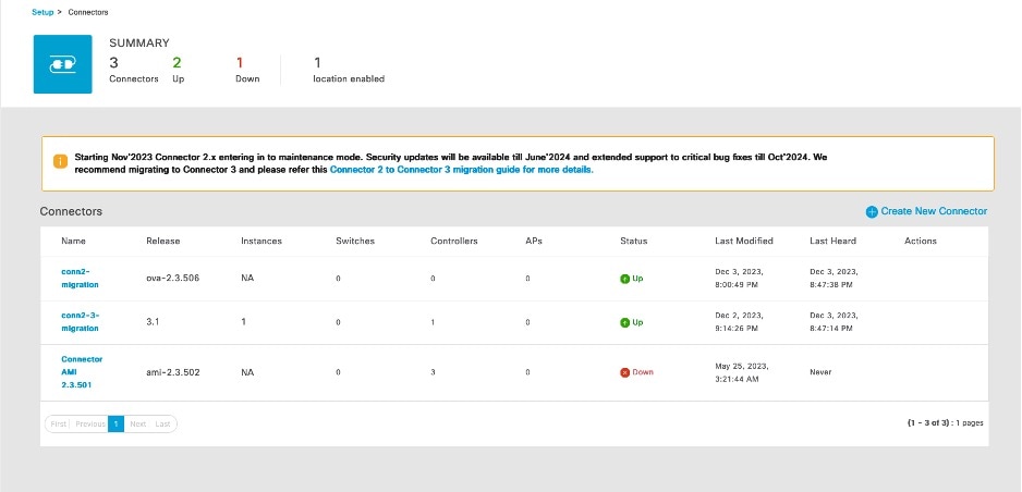
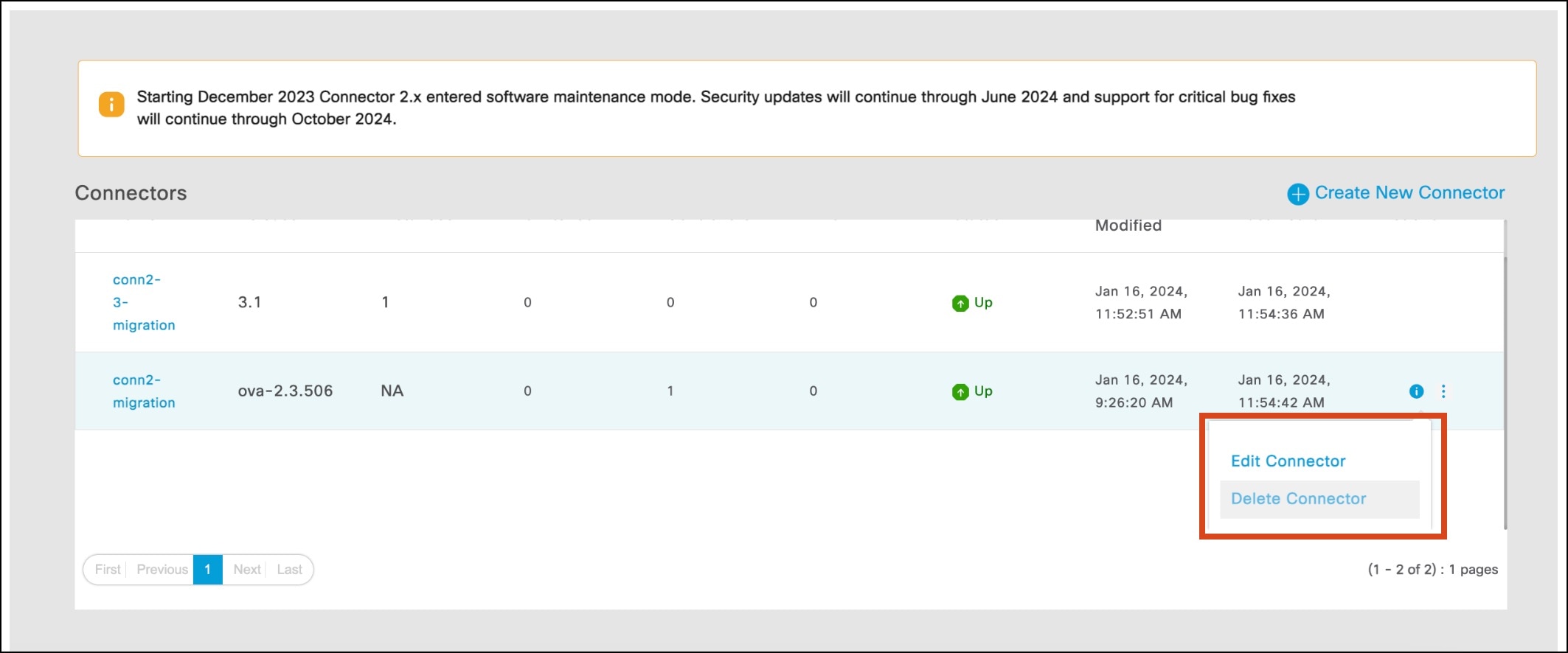
Step 3 | From the 2. Configure the Spaces Connector area, click View Connectors. 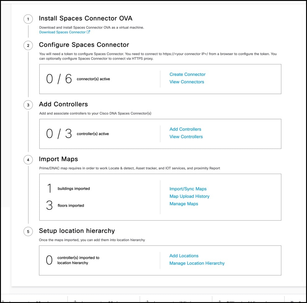
|
Step 4 | From the list of connectors displayed, click the connector 3 you installed. Click Add Controller. 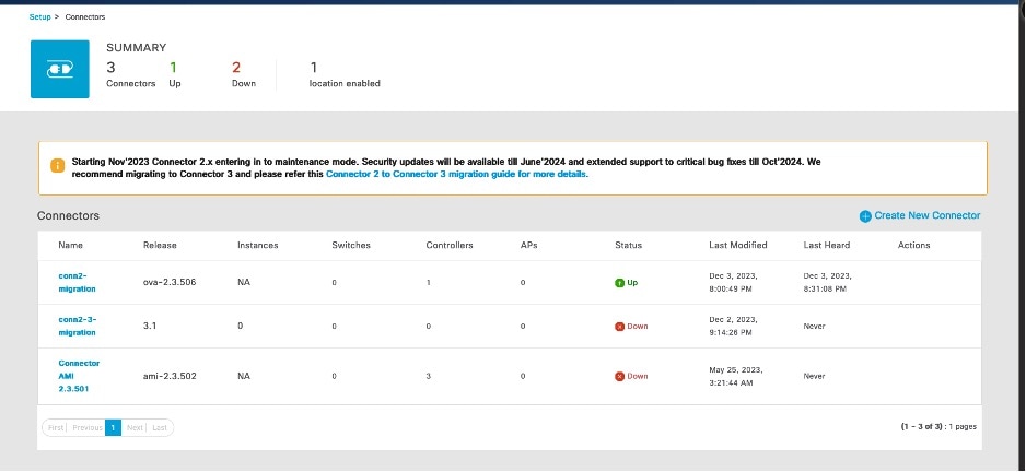
|
Step 5 | From the Add Controller tab of this specific connector, click Choose controllers from another connector. From the Choose connector drop-down list displayed, choose the connector 2.x that you want to migrate configurations from. 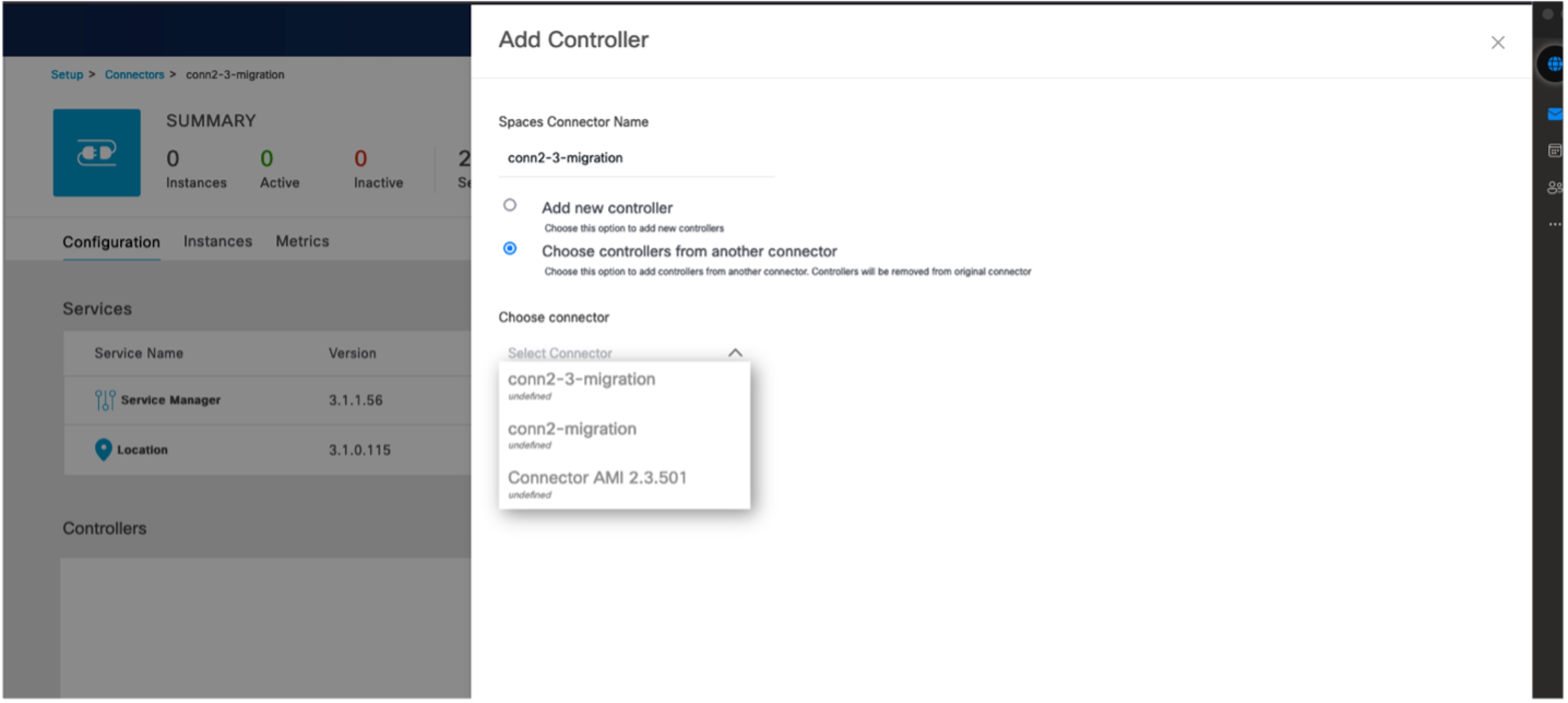
|
Step 6 | To migrate hotspot configurations from the connector 2.x, check the Migrate hotspot configurations from the selected connector check box. 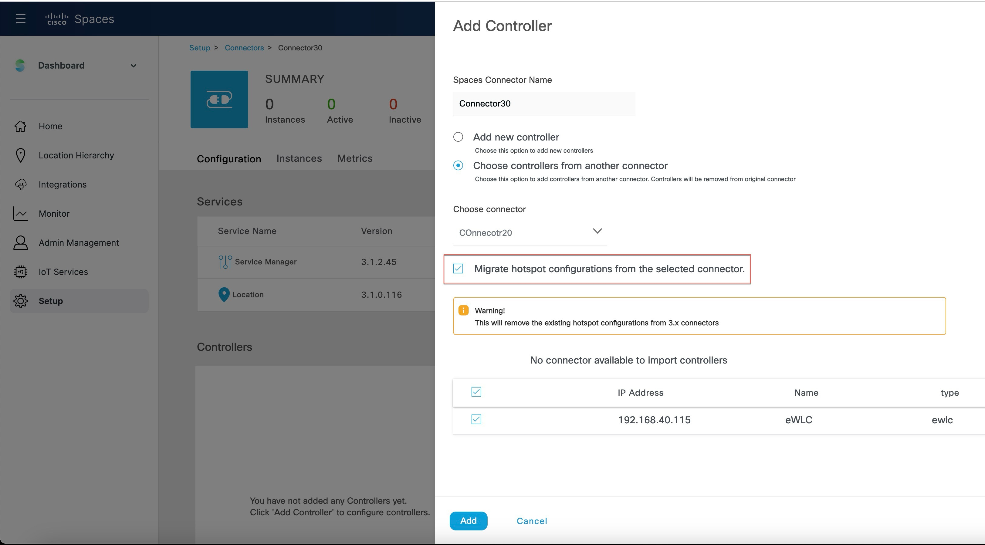 Note
NoteThe following points are related to the migration of Hotspot Service:
|
Verify the Migration Status of Connector 3
In the Setup > Connector window, observe the status of migration. Wait for the value of the Status cell of the Connector 3 to change from Down to Up.
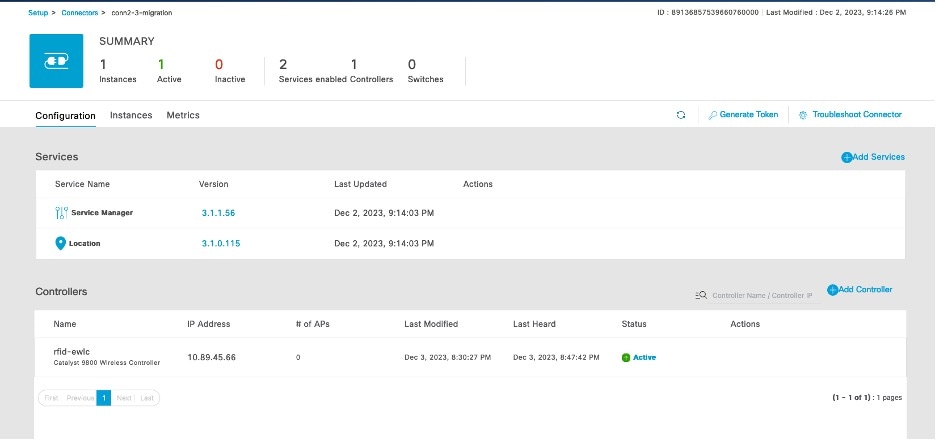
Verify Wireless Controllers, APs, and Location Service
 Note
NoteThe time it takes for the controller to reach an ACTIVE state may differ based on the number of services chosen and the size of the deployment; however, we recommend that you wait a few minutes for this process to be completed.
Verify IoT Service (Wireless)
Step 1 | In the Cisco Spaces dashboard, choose Setup > Wireless Networks > 2. Configure the Spaces Connector area > View Connectors. |
Step 2 | From the list of Connectors displayed, choose the newly migrated connector 3. |
Step 3 | From the list of services, click the gear icon on the IoT Wireless row and from the pop-up menu, choose IoT Stream. 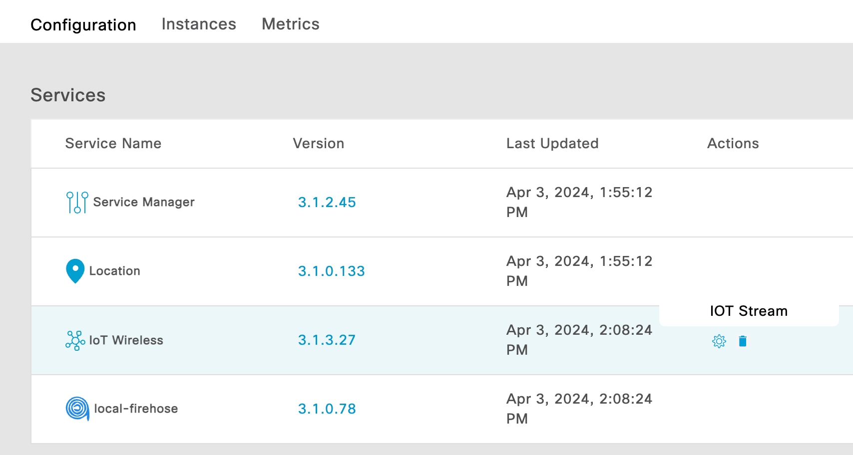
|
Step 4 | In the Manage IoT Streams window, check the Operation Log and ensure that the status is Successfully set config. 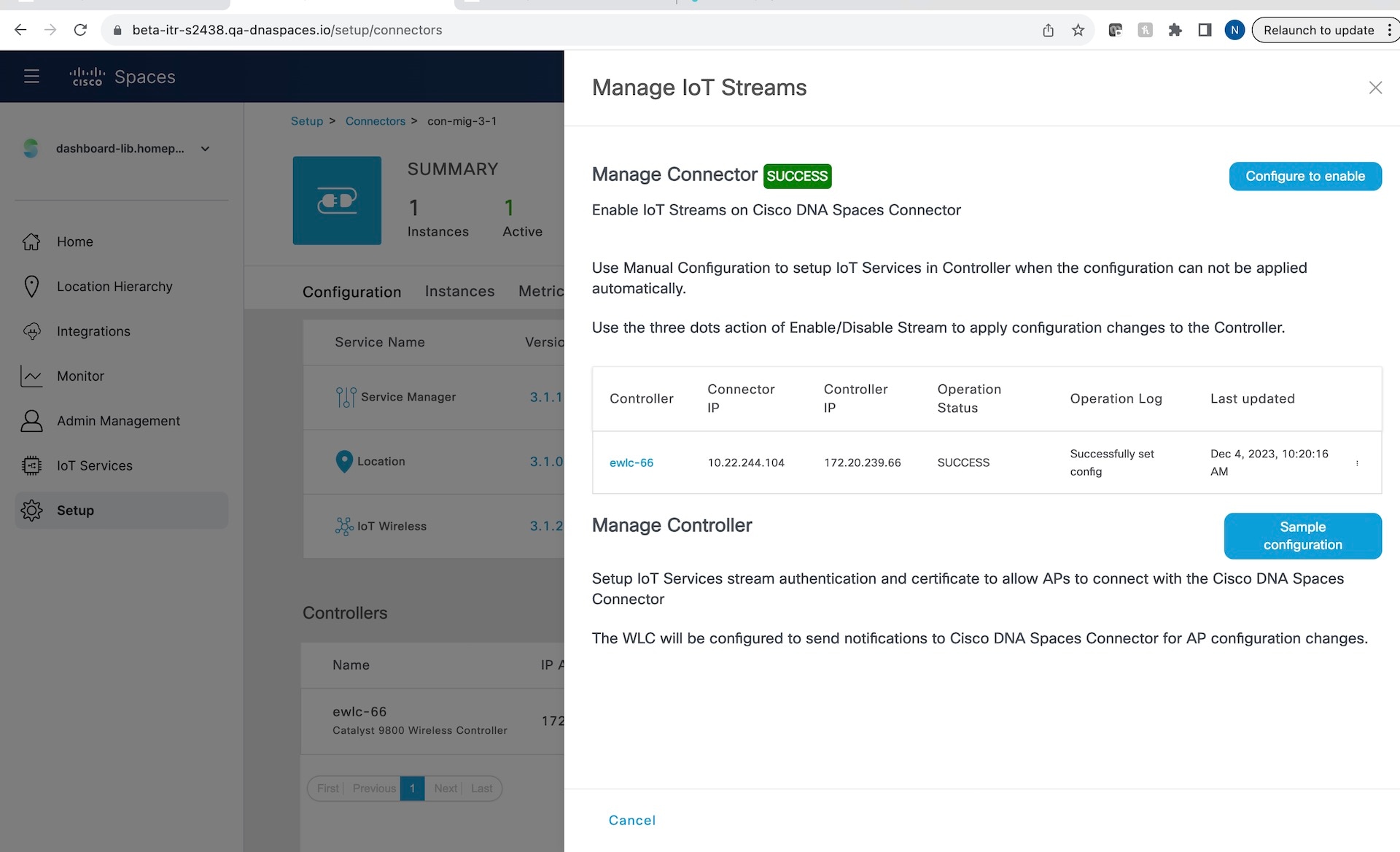
|
Verify Hotspot Service
Step 1 | In the Cisco Spaces dashboard, choose OpenRoaming. In the OpenRoaming left-navigation pane, choose Setup. |
Step 2 | In the Hotspot-enabled Connectors area, choose Cisco Wireless Controllers. |
Step 3 | Verify if the new Connector 3 instance is in the ACTIVE state. 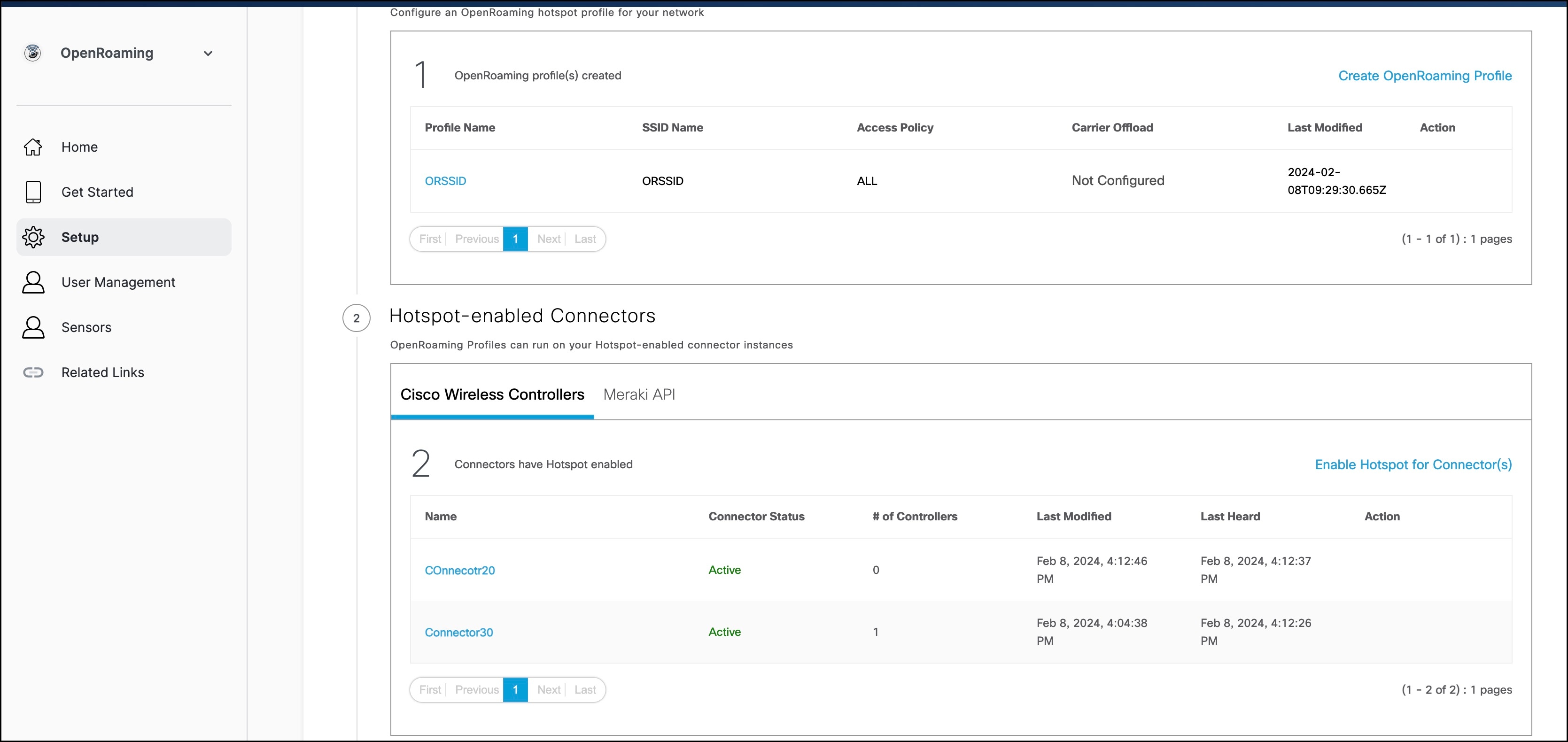 |
Configure Local Firehose
Step 1 | In the Cisco Spaces dashboard left navigation pane, click Setup and choose Wireless Networks. |
Step 2 | In the Connect your wireless network window that is displayed, go to the Step 2 area and click View Connectors. 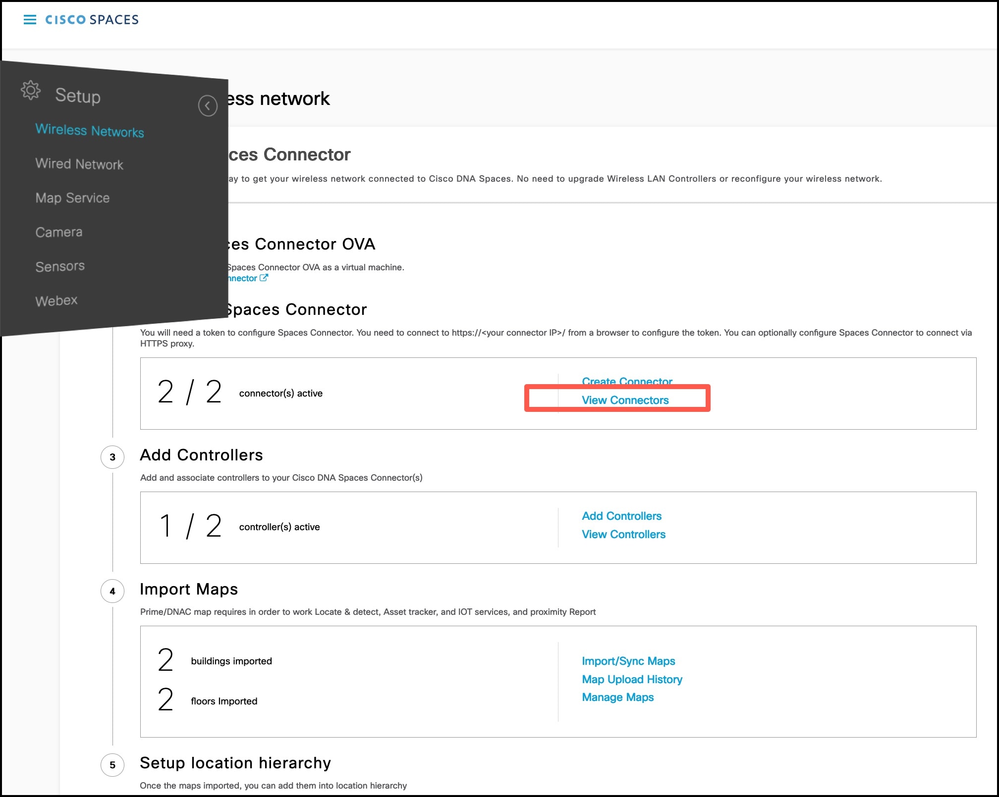
|
Step 3 | In the connector details window that is displayed, choose a connector and click Add Services. 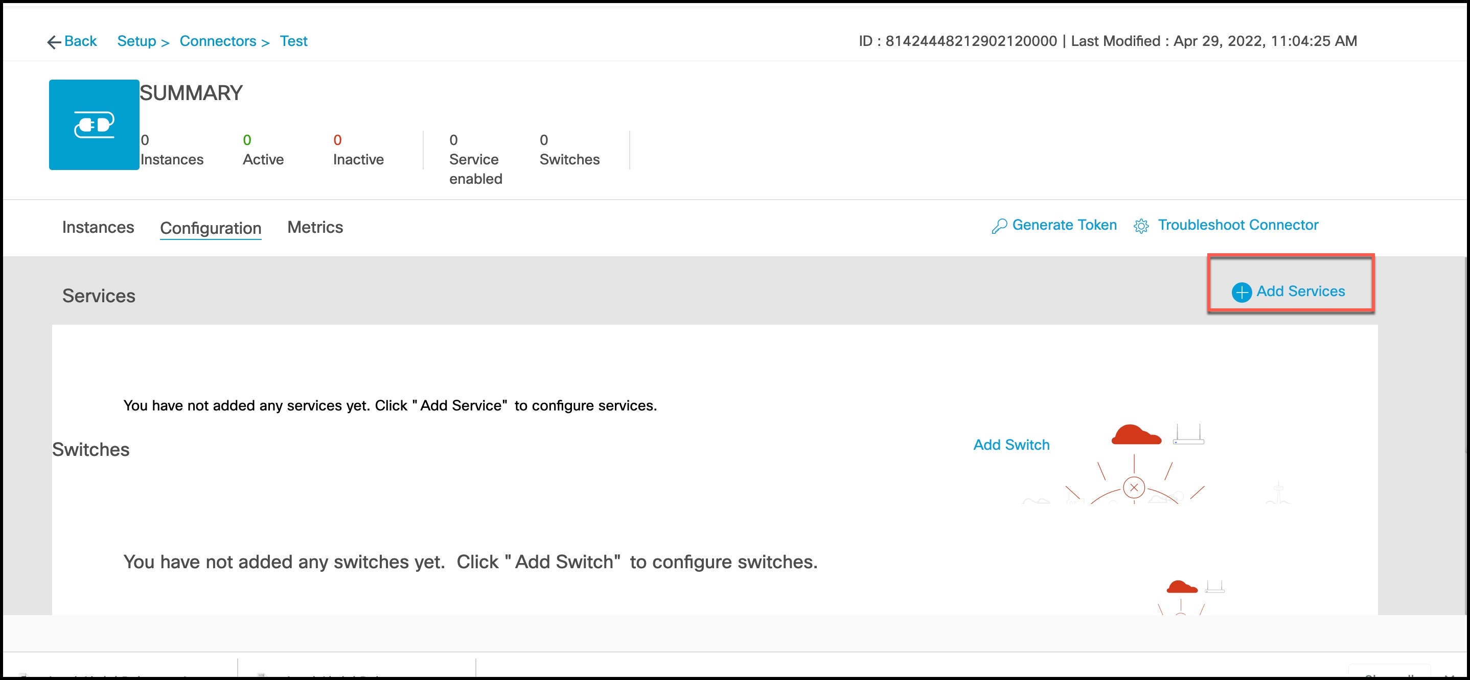
|
Step 4 | In the Add Service window that is displayed, choose local-firehose and click Add. NoteTo receive events such as Device_RSSI for Received Signal Strength Indicator (RSSI)-based tags and Device_BLE events for Bluetooth Low Energy (BLE) tags, ensure that location and iot-services services are also added. You can see that the number of services enabled has increased. |
Step 5 | Login to the Connector GUI. Scroll downwards to the local-firehose tile. Verify if the running status is Up. 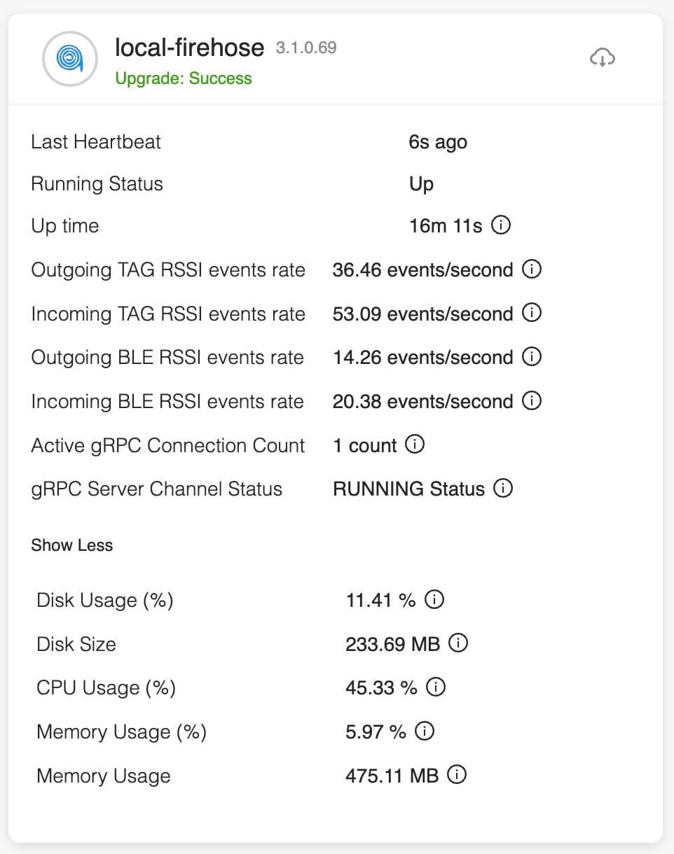
|
What's next
-
Stanley customers using the Aeroscout Location Engine (ALE) should update the IP address of the Connector 2.x instance to the IP address of the Connector 3 instance.
-
All other customers must update their applications with the new Connector 3 instance IP address.
-
If the Connector3 is configured in High Availability VIP mode, both the primary and secondary Connector 3 instance IPs must be utilized in the ALE.
-
The API key for the local firehose remains unchanged and is the same as the one generated for Connector 2.
Last Steps
Once migrations is completed, and verified, remove Connector 2.x instances from the Cisco Spaces dashboard.
For Your Reference
Configure IoT Service (Wireless)
Step 1 | In the Cisco Spaces dashboard left navigation pane, click Setup and choose Wireless Networks. |
Step 2 | In the Connect your wireless network window that is displayed, go to the Step 2 area and click View Connectors.
|
Step 3 | In the connector details window that is displayed, click Add Services.
|
Step 4 | In the Add Services window that is displayed, choose IoT Wireless and click Add. Noteservice-manager is chosen by default. 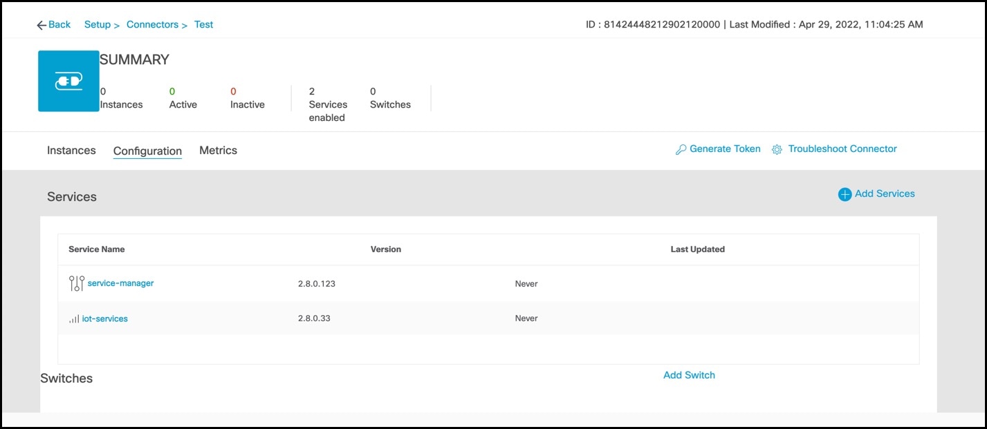
In the Connector Details window, you can see that the number of services that are enabled has increased. |
Configure IoT Service (Wired)
Step 1 | From the Cisco Spaces dashboard left-navigation pane, click Setup and choose Wired Networks. |
Step 2 | From the Connect your wireless network window that is displayed, go to the Step 2 area and click View Connectors.
|
Step 3 | Click a connector 3 of your choice. NoteYou can use the same connector that you used for Cisco Spaces: IoT Service (Wireless). |
Step 4 | In the connector details window that is displayed, click Add Services.
|
Step 5 | In the Add Service window that is displayed, choose IoT Wired and click Add.
In the Connector Details window, you can see that the IoT Wired service has been added. |
Step 6 | Click the gear icon near the IoT Wired row. 
|
Step 7 | (Optional) In the Manage IoT Streams window that is displayed, check if the connector is not already enabled, and if it is not, click Configure to Enable. |
Step 8 | From the list of switches, click the vertical three-dot icon adjacent to the switch and select Enable Service. 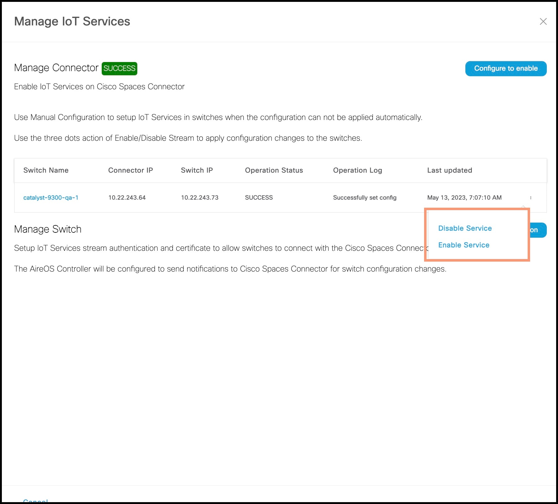 Note
NoteIf you are using the same connector for both wired and wireless IoT services, the connector is already enabled. |
Step 9 | Enter the SPAN VLAN and the Cisco IOx App details.
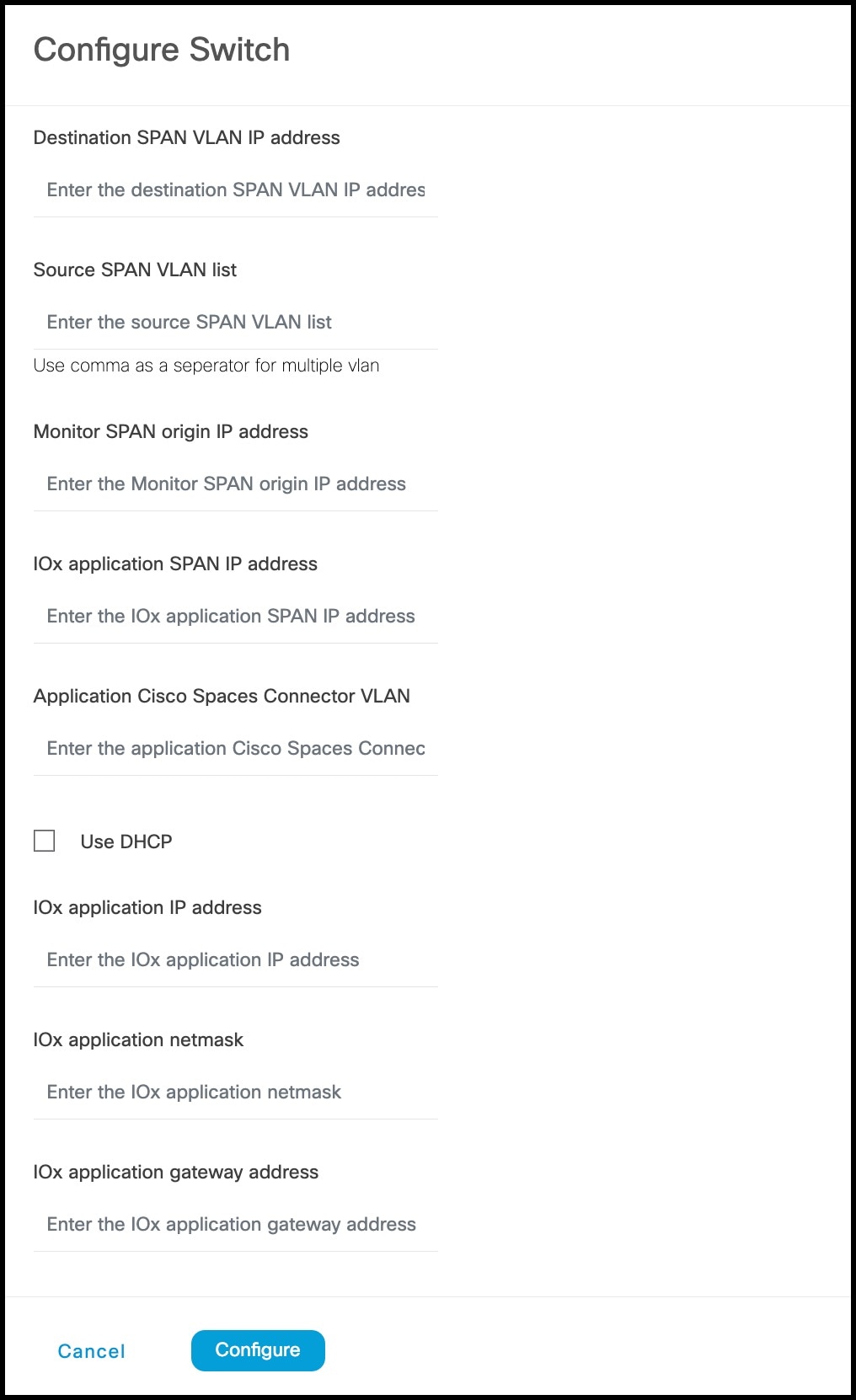
|
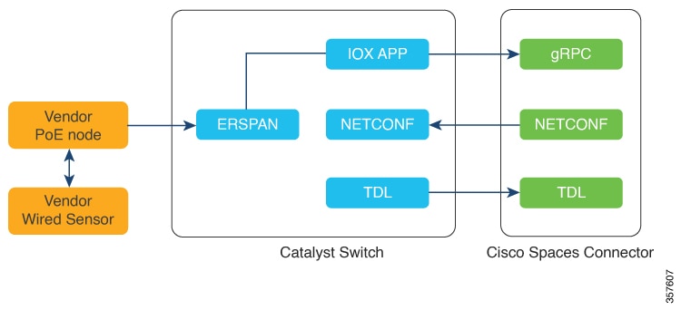
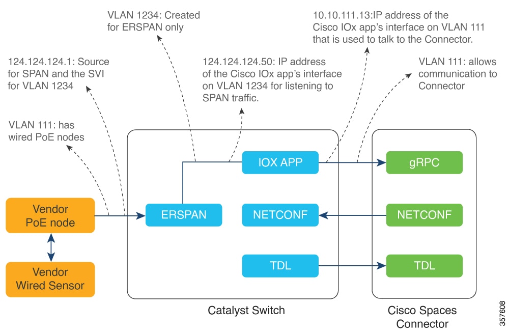
Step 10 | Click Configure. The configurations are deployed on the switch. The following diagram shows the corresponding CLI commands you can use in place of the GUI configuration. 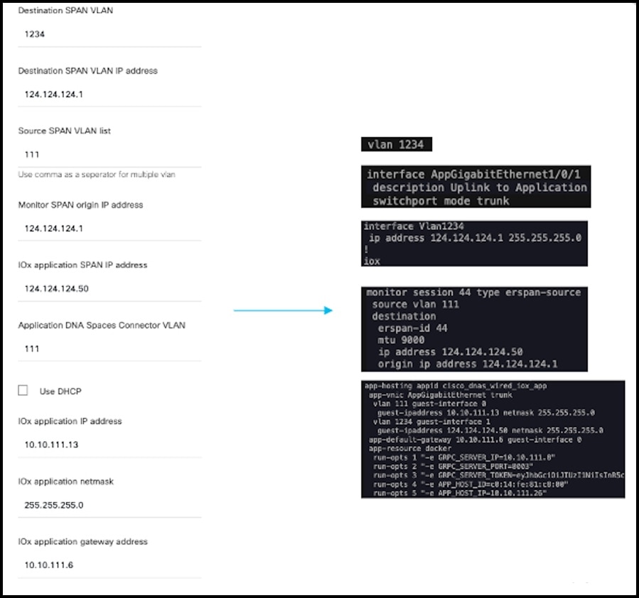
|
Step 11 | In the Manage IoT Services window that you are taken to, you can click on a name of the switch to see the list of steps executed on that switch. 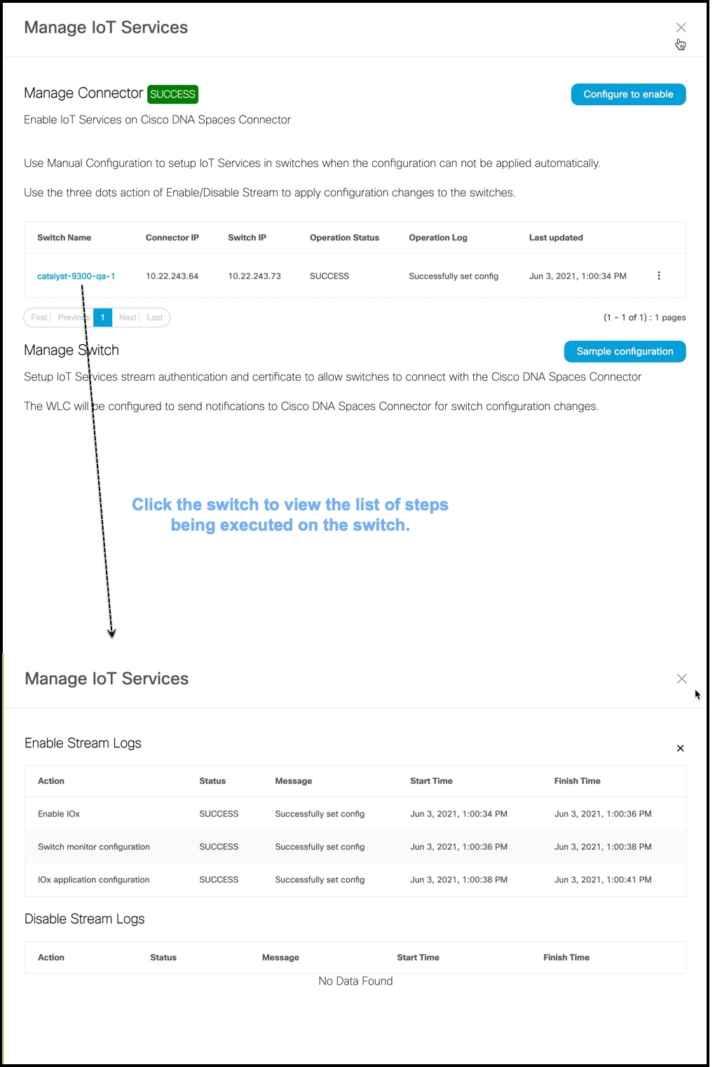
|
Configure Hotspot Service
Step 1 | In the Cisco Spaces dashboard left navigation pane, click Setup and choose Wireless Networks. |
Step 2 | In the Connect your wireless network window that is displayed, go to the Step 2 area and click View Connectors.
|
Step 3 | In the connector details window that is displayed, choose a connector and click Add Services.
|
Step 4 | In the Add Service window that is displayed, choose hotspot and click Add. Noteservice-manager is added by default. In the Connector Details
window, you can see that the number of services enabled has increased. |
Configure Local Firehose Service
Step 1 | In the Cisco Spaces dashboard left navigation pane, click Setup and choose Wireless Networks. |
Step 2 | In the Connect your wireless network window that is displayed, go to the Step 2 area and click View Connectors.
|
Step 3 | In the connector details window that is displayed, choose a connector and click Add Services.
|
Step 4 | In the Add Service window that is displayed, choose local-firehose and click Add. NoteTo receive events such as Device_RSSI for Received Signal Strength Indicator (RSSI)-based tags and Device_BLE events for Bluetooth Low Energy (BLE) tags, ensure that location and iot-services services are also added. You can see that the number of services enabled has increased. |
Step 5 | Login to the Connector GUI. Scroll downwards to the local-firehose tile. Verify if the running status is Up.
|
Configure Cisco AireOS or Cisco Catalyst Network
Before you begin
Before you configure the Cisco AireOS or Cisco Catalyst wireless network, you must configure the SSID and AAA policy.
Step 1 | In the OpenRoaming window, click Set Up OpenRoaming or choose The OpenRoaming Setup page is displayed. NoteIf you have completed the OpenRoaming Profile configuration, click Continue OR Setup in the configuration wizard to proceed. In the Network configuration section, under the AireOS/Catalyst controllers tab, a list of all the Cisco AireOS and Cisco Catalyst series controllers appears with details such as the Controller status and associated Connectors. |
Step 2 | Under , in the Action column, click the settings The Configure Controller window is displayed. |
Step 3 | Under Generate Configuration, select the OpenRoaming profile from the drop-down list. If a non-default policy profile or policy tag is used, you must copy only the Access Network Query Protocol (ANQP) server settings and apply it to the wireless policy profile. Ensure that the policy tag uses the WLAN configured for OpenRoaming, and is mapped to the configured wireless policy profile. |
Step 4 | Paste the selected OpenRoaming profile configuration in the Cisco AireOS or Catalyst controller CLI. NoteOnly CLI-based configuration is supported. |
Step 5 | Click Continue. A Controller configured with profile successfully message is displayed. |
Step 6 | Choose the controller type between AireOS and Catalyst 9800. |
Step 7 | In the WLAN ID field, enter a WLAN ID if your existing network is based on a Cisco AireOS Controller. Specify the WLAN name if it is based on a Cisco Catalyst Controller. |
Step 8 | Click Close. The OpenRoaming Setup window is displayed. |
