Cisco ONS 15454 RAN Service Module Installation Instructions
Available Languages
Table Of Contents
Cisco ONS 15454 RAN Service Module Installation Instructions
RAN Optimization Implementation
Cisco ONS 15454 RAN Service Module
Cisco ONS 15454 RAN Service Module Card-Level Indicators
Cisco ONS 15454 RAN Service Module Port-Level Indicators
Installing the Cisco ONS 15454 RAN Service Module
Connecting the Cisco ONS 15454 RAN Service Module
Obtaining Documentation, Obtaining Support, and Security Guidelines
Cisco ONS 15454 RAN Service Module Installation Instructions
February 11, 2008
OL-12941-02
Product Number: 15454E-RAN-SVC (ETSI) or 15454-RAN-SVC (ANSI)This document provides module/card specifications and describes installation and removal procedures for the Cisco ONS 15454 RAN Service Module. Use this document in conjunction with the Cisco ONS 15454 Procedure Guide or the Cisco ONS 15454 SDH Procedure Guide, the Cisco ONS 15454 Reference Manual or the Cisco ONS 15454 SDH Reference Guide, and the Cisco ONS 15454 Troubleshooting Guide or the Cisco ONS 15454 SDH Troubleshooting Guide when working with RAN Service Modules.
This document contains the following sections:
•
Cisco ONS 15454 RAN Service Module
•
•
•
Document Revision History
The Document Revision History table below records technical changes to this document. The table shows the document revision number for the change, the date of the change, and a brief summary of the change. Note that not all Cisco documents use a Document Revision History table.
78-17278-02
February 11, 2008
Updates to LED operation, hardware description, and installation.
78-17278-01
February 2, 2007
This is the first release of this guide.
Introduction
A typical RAN is composed of thousands of Base Transceiver Stations/Node Bs, hundreds of Base Station Controllers/Radio Network Controllers (BSCs/RNCs), and several Mobile Switching Centers (MSCs). The BTSs/Node Bs and BSCs/RNCs are often separated by large geographic distances, with the BTSs/Node Bs located in cell sites uniformly distributed throughout a region, and the BSCs, RNCs, and MSCs located at suitably selected Central Offices (COs) and/or Mobile Telephone Switching Offices (MTSOs). The traffic generated by a BTS/Node B is transported to the corresponding BSC/RNC across a network, referred to as the backhaul network, which is often a hub-and-spoke topology with hundreds of BTSs/Node Bs connected to a given BSC/RNC by point-to-point TDM trunks. These TDM trunks may be leased line T1/E1s or their logical equivalents, such as microwave links or satellite channels. The interface between the BTS and BSC in Global System for Communication (GSM) and Code Division Multiplex Access (CDMA) systems is called the Abis interface. The interface between the Node B and RNC in a Universal Mobile Telecommunication System (UMTS) is called the Iub interface.
RAN Optimization Implementation
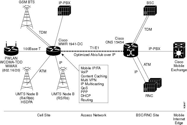
In RAN Optimization (RAN-O), the Cisco MWR 1941-DC-A router extends IP connectivity to the cell site and the BTS/Node B. The router provides bandwidth-efficient IP transport of GSM and UMTS voice and data bearer traffic, as well as maintenance, control, and signaling traffic, over the leased line backhaul network between the BTS/Node B and leased line termination and the Cisco ONS 15454 aggregation node via compression (cRTP/cUDP) and packet multiplexing (Multilink PPP).
The Cisco ONS 15454 RAN Service Module implements the aggregation node functionality with the Cisco RAN -O solution. In the Cisco ONS 15454, the Cisco ONS RAN Service Module transmits and receives E1 data steams (for Abis) and OC-3 data streams (for UMTS) via the cross-connect cards.
Figure 1 shows an example of the Cisco MWR 1941-DC-A and Cisco ONS 15454 connected via an optimized Abis and Iub over IP interface.
Figure 1 Example of Cisco MWR 1941-DC-A and Cisco ONS 15454 in a Cell Site POP
Cisco ONS 15454 RAN Service Module
Residing in a Cisco ONS 15454, the Cisco RAN Service Module provides aggregation for traffic originating from multiple MWR cell site routers. The RAN Service Module transmits and receives short haul DS0 level data steams (for GSM applications) and shorthaul VC-4 level data streams (for UMTS applications) through ONS 15454 cross-connect cards. DS0 level channel cards connect both the long haul to the remote cell site and the short haul to GSM BSC. Clear channel VC-4 level interface cards are used on the Cisco ONS 15454 to provide the interface from the UMTS RNC to the ONS RAN Service Module.
In the Cisco ONS 15454 SDH, the Cisco E1-42 cards are used to connect both the long haul E1 to the remote cell site and also the short haul E1 to the BSCs/RNCs. The Cisco ONS 15454 RAN Service Module transmits and receives E1 data streams (for GSM applications) and OC-3 data streams (for UMTS applications) via the Cross Connect cards. For E1 connections (GSM and/or backhaul), as many as 126 E1 interfaces from multiple E1-42 cards may be groomed by the Cross Connect card to form two STM-1 data streams which are directed to and terminated on the Cisco ONS 15454 RAN Service Module. For OC-3 interfaces (Packet of Sonet [POS] and/or ATM), as many as eight OC-3 interfaces from multiple OC-3 cards may be groomed by the Cross Connect card to form two STM-4 data streams which are directed to and terminated on the Cisco ONS 15454 RAN Service Module as well.
Hardware Description
The Cisco RAN Service Module consists of four independent IOS processors. Contained in a circuit card enclosure, the Cisco ONS 15454 RAN Service Module weighs 3.1 pounds (1.3 kg) and measures 12.65 in. high x 0.716 in. wide x 9.0 in. deep (32.13 cm x 1.82 cm x 22.86 cm).
Each Cisco RAN Service Module has four 10/100/1000 Gigabit Ethernet (RJ-45) ports with one port connected to each IOS processor. The Cisco RAN Service Module is also equipped with four VC-4 level Packet over SONET (POS) interfaces and four VC-4 level ATM interfaces. The DSO are maped with a maximum of 126 DSO/E1 interfaces that are distributed among the traffic CPUs for backhaul and shorthaul interfaces depending upon the application. We support a maximum of 96 for GSM-ABIS shorthaul interfaces and a maximum of 48 HDLC/PPP/backhaul interfaces

Note
One IOS processor is dedicated as a service processor while the remaining three IOS processors are dedicated as traffic processors. The Cisco ONS 15454 RAN Service Module also includes two RJ-45 ports, one used as a DCE console (labeled Console) and the other used as a debug port (covered with a tab plate).
The Cisco ONS 15454 shelf assembly has 17 card slots that are numbered sequentially from left to right. Slots 1 - 4 and 14 - 17 are multispeed slots. Slots 5, 6, 12 and 13 are high-speed slots. Slots 7 and 11 are dedicated to TCC-I cards. Slots 8 and 10 are dedicated to cross-connect (XC10G) cards. Slot 9 is dedicated to the AIC card. Slots 3 and 15 can host E1N-14 and DS3i-N-12 cards that are used in 1:N protection. The Cisco ONS RAN Service Module can be installed in Slots 1 thru 6 or 12 thru 17 depending on the application and line card configuration.
Note
Faceplate Features
On the Cisco ONS 15454 RAN Service Module faceplate (see Figure 2), two LEDs (labeled FAIL (for board failure) and ACT/STBY (for active and standby) are provided (see Table 1 for a description). The 10/100/1000 Ethernet (RJ-45) ports (also located on the front panel) are labeled 0, 1, 2, and 3. Each port has two status LEDs, a link status LED (steady green indicating a link up) and a link activity LED (blinking yellow indicating RX/TX activity).
Note
Figure 2 Cisco ONS 15454 RAN Service Module Front Panel

Cisco ONS 15454 RAN Service Module Card-Level Indicators
The Cisco ONS 15454 RAN Service Module has two card-level LEDs as described in Table 1.
Cisco ONS 15454 RAN Service Module Port-Level Indicators
You can find the status of the Cisco ONS 15454 RAN Service Module ports using the LCD screen on the ONS 15454 SDH fan tray assembly. Use the LCD to view the status of any port or card slot; the screen displays the number and severity of alarms for a given port or slot. Refer the Cisco ONS 15454 SDH Troubleshooting Guide for a complete description of the alarm messages.
Specifications
The Cisco ONS 15454 RAN Service Module has the following specifications:
•
–
C-Temp: 32 to 104°F (0 to 40°C)
–
–
•
–
–
–
–
•
–
Installing the Cisco ONS 15454 RAN Service Module
Use this section if you are installing the Cisco ONS 15454 RAN Service Module for the first time. After you become familiar with the Cisco ONS 15454 RAN Service Module installation, use this section as a reference.
Note
Note

Caution

Warning
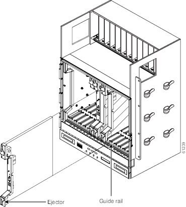
Figure 3 Installing cards in an ONS 15454 SDH
Step 1
Step 2
Note
Step 3
Step 4
•
•
•
•
Note
Note
Note
Step 5
Note
Connecting the Cisco ONS 15454 RAN Service Module
How you connect the ports of the Cisco ONS 15454 RAN Service Module depends on whether you are using the Cisco ONS 15454-SDH in a redundant or a non-redundant configuration.
Note
For information on Cisco ONS 15454-SDH implementations, refer to the Cisco ONS 15454-SDH Software Configuration Guide.
Related Documentation
This document provides information on the Cisco ONS 15454 RAN Service Module and supplements the Cisco Interface Modules Hardware Installation Guide.
Use this document with the following guides:
•
–
–
–
•
–
–
•
Obtaining Documentation, Obtaining Support, and Security Guidelines
For information on obtaining documentation, obtaining support, providing documentation feedback, security guidelines, and also recommended aliases and general Cisco documents, see the monthly What's New in Cisco Product Documentation, which also lists all new and revised Cisco technical documentation, at:
http://www.cisco.com/en/US/docs/general/whatsnew/whatsnew.html
 Feedback