Cisco 6300 Embedded Services Access Points (ESW-6300) RF and Mechanical Integration Guide
Overview
This reference design provides mounting details, antenna spacing and configuration guidelines, environmental guidelines, and other operational guidelines pertaining to the integration of the Cisco® ESW-6300 embedded wireless product into a third-party outdoor enclosure.
This reference design provides an example of how to integrate the embedded wireless product into an appropriate third-party enclosure and describes the hardware that is compatible with the access point. Note that this document may not explain specific needs for every method of integration. The included drawings of the Cisco product are accurate; any dimensions of third-party equipment are for reference only.
Summary
The ESW-6300 unit is designed to be embedded into a custom or modified off the shelf enclosure that is not designed, manufactured or productized by Cisco. The ESW-6300 can be mounted in any direction, provided it is fastened down at each of its 4 separate mounting points (i.e., two on the top of the module and one on each side). The ESW-6300 has four SMA jack RF coaxial connectors to connect to two dual band or four single band external antennas. The reset button and console port are accessed through a port on the right side of the unit where the words “RESET” and “CON” are shown. It is important that the partner-provided enclosure allows enough room to access these ports for troubleshooting and diagnostics. This document will not comment on the integration or procurement of other devices such as power supplies, injectors, radios, etc. It will be limited to the integration of the ESW-6300 only. If additional devices are to be installed, then the size of the enclosure must be increased accordingly.
Audience
This guide is intended for purchasers and/or integrators of the ESW-6300 Embedded Services Access Point.
Product Category
The ESW-6300 is an IP30 rated product. If it is deployed outdoors, then it must be integrated into an IP65 or greater enclosure.
ESW-6300 Outline
The ESW-6300 is made from Alodined diecast Aluminum Alloy A413 and weighs 3.2 lbs. The back of the access point is designed to be heat sunk. For optimal performance, the main heatsink (the back), shown as “Mounting Surface (Main Heatsink)” in Figure 3 below should be mounted to a flat and thermally conductive material that has an efficient thermal path to the external ambient air for optimal thermal performance. There are also two optional heatsinks shown as “2X Heatsink Surface” on Figure 2 below (the front). External ambient maximum temperature could be marginally increased if heatsinks are applied to additional thermal interface surface. A specific thermal interface material is not required.
Mounting the ESW-6300
Mounting hardware
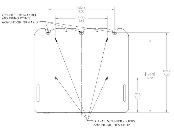
There are four mounting points for the ESW-6300. These locations are designed to use a #6 or M3.5 Pan Head screw with small pattern washer (0.260 inches in max diameter).
The outer diameter of the washer and the screw head cannot be larger than 0.260 inches; otherwise they will not seat properly. Screw length should be long enough to ensure five threads of engagement into the mating surface. Additionally a locking method such as a lock washer or Loctite should be employed.
Figure 4 above shows the typical mounting locations on the ESW-6300. The threads and holes on the back (shown in Figure 5), on the heat sink side of the ESW-6300 are for rear mounting or attaching the DIN rail bracket. Front mounting is recommended.
Enclosure Design
Sizing Recommendations
An enclosure greater than or equal to 12 inches tall x 10 inches wide x 4 inches deep is recommended. Actual enclosure size may vary due to individual needs or if additional devices are to be installed with the ESW-6300. Figure 6 shows how it fits in the smallest recommended IP66/68 enclosure. This spacing allows for reasonable space to access all usable ports and buttons.
It is highly recommended that the enclosure you choose is made of a non-corrosive or corrosion resistant material.
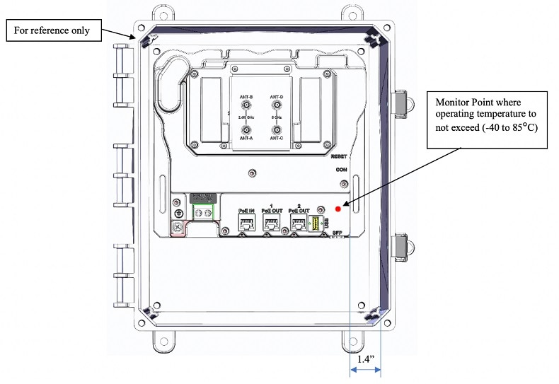
Reset and console ports are located on the right side of the access point. There should be enough room available on that side for easy access of these ports to engage a RJ45 cable. As a reference, Figure 6 shows just under 1.4 inches of space between the wall and the two “RESET” and “CON” labels.
Environmental Specification
The enclosure of choice must have an IP65 or higher certification if it is to be mounted in a non-controlled environment. The enclosure must be sealed from dust and hose-downs such as power washing.
The ESW-6300 has an operating case temperature range of -40 to 85°C. The monitor point location where this operating temperature range should not be exceeded is shown in Figure 6. The external operating temperature range of the overall enclosure assembly will be limited by the ESW-6300 monitor point thermal limits, or any other component within the enclosure that has thermal limits less than the ESW-6300. Actual external ambient temperatures should be determined by testing or thermal analysis. For example, in the non-metallic enclosure shown in Figure 6 the external ambient will be limited to roughly 45°C maximum. Solar load should be included if applicable.
RF Configurations
The ESW-6300 is a Wi-Fi access point including a 2x2 MIMO 2.4 GHz radio and a 2x2 MIMO 5 GHz radio.
The ESW-6300 may be configured to operate in dual band or single band mode.
-
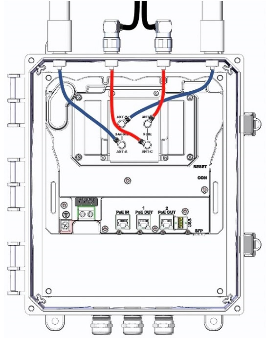
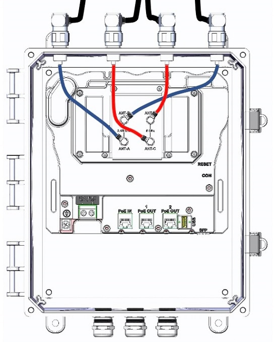
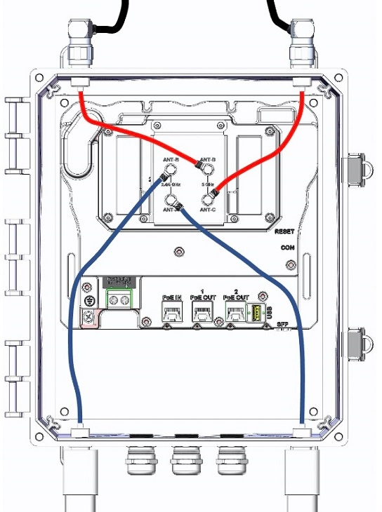
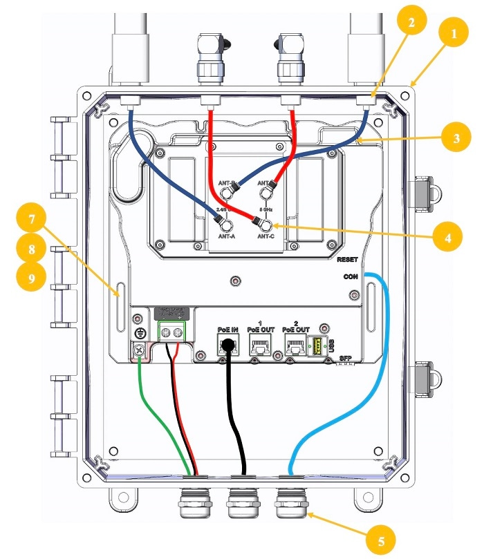
In dual band mode the 2.4 GHz and 5 GHz signals are diplexed onto the two antenna ports labeled “2.4/5 GHz ANT-A” and “2.4/5 GHz ANT-B”. The two antenna ports labeled “5 GHz ANT-C” and “5 GHz ANT-D” are not used.
-
In single band mode the 2.4 GHz radio uses the two antenna ports labeled “2.4/5 GHz ANT-A” and “2.4/5 GHz ANT-B” and the 5 GHz radio uses the two antenna ports labeled “5 GHz ANT-C” and “5 GHz ANT-D”.
Any omnidirectional antenna mounted directly to the enclosure housing the ESW-6300 can only be mounted vertically.
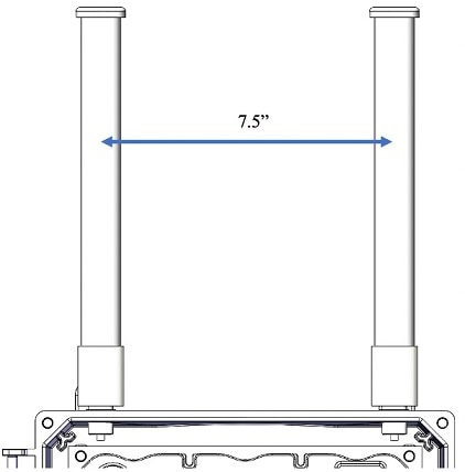
2.4 GHz antennas mounted directly to the enclosure should be spaced at least 6 inches apart, center to center. If allowed, separation of 7.5 inches or greater is recommended for optimal MIMO performance. 5 GHz antennas mounted directly to the enclosure should be spaced at least 3 inches apart, center to center. Any spacing less than 6 inches between 2.4 GHz antennas or 3 inches between 5 GHz antennas may limit the ability of the radio to demodulate two independent spatial streams, resulting in reduced throughput.
In Figure 7, the antennas are spaced 7.5 inches apart on the same enclosure as Figure 3. If you require other antennas on your enclosure for other products, it is important to keep them away from the antennas for the ESW-6300 Wi-Fi access point. For example, at least 40 dB isolation must be maintained between any 2.4 GHz Wi-Fi antenna and any 2.4 GHz 802.15.4 radio.
The cables routing to the antennas will be of different lengths depending on the enclosure of choice and the antenna locations. The ESW-6300 uses four antennas when configured in single-band antenna mode. Possible configurations are shown in Table 1. If you plan on using the two optional front heatsinks, the cables must be routed to avoid interference between the heatsink and the thermally conductive mating surface.
Cable ties or clamps should be used to eliminate any routing or handling stress transmitted to the ESW-6300 SMA connectors.
 Note |
Cable routing shown below is for configuration reference only. Actual routing should employ standard practices such as, avoid routing over areas that could cause abrasion, avoid restricting I/O connectors or hardware access, provide ample cable strain relief and minimum bend radius and provide locations for cable ties. |
|
1. Omnidirectional coverage with dual-band antennas |

|
|
|
2. Local coverage on 2.4GHz; backhaul on 5 GHz |
|
|
|
3. All antennas mounted remotely |
|
|
|
4. Local coverage with one radio, remotely mounted backhaul on the other radio, variant |
|
|
|
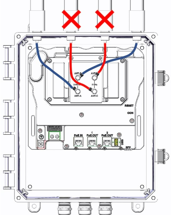
5. Incorrect setup. Do not do this. 4 adjacent antennas. |
|
|
Internal RF Cables and Bulkhead Connectors
The internal cables connect to external antennas or coaxial cables via a N-type straight jack bulkhead connector. Holes must be drilled/punched in the enclosure for the connectors to be mounted in.
The size of the holes depend on which bulkhead connector is chosen. The bulkhead shown on the 3D models on this document is representative of the style recommended. Selection of connector and manufacturer is solely the responsibility of the integrator. Any part numbers supplied by Cisco are for reference only and no guarantee is implied.
The manufacturer’s part number for the style shown in this document can be found in the section Suggested Parts. A “punch tool” is also referenced. Punch tools are a convenient method for putting a “D” or “Double-D” hole into the enclosure. A number of manufacturers make these tools, and the tool has to be matched with the connector that is selected.
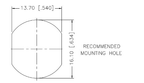
The suggested hole cut out for the N-type bulkhead referenced in the layouts is shown in Figure 8. Connector holes should employ an anti-rotation feature, such as a “D” hole or “Double D” hole as shown in Figure 8. The actual dimensions of such a hole are dependent on the actual connector selected. The dimensions in Figure 8 are for reference only, and apply only to the connector shown in our reference design.
It is important that the cables are never bent or formed beyond the minimum bend radius found in their data sheet. Table 2 shows bend radius limitations for several different cables. Many other cables not listed may be used.
|
Coaxial Cable Manufacturer and Part Number |
Nominal Outside Diameter (inches, mm) |
Static Minimum Bend Radius (inches, mm) |
Repeated Minimum Bend Radius (inches, mm) |
|---|---|---|---|
|
Times Microwave LMR-100A |
0.110, 2.79 |
0.25, 6.4 |
1.0, 25.4 |
|
Times Microwave LMR-195 |
0.195, 4.95 |
0.5, 12.7 |
2.0, 50.8 |
|
Times Microwave LMR-240 |
0.240, 6.10 |
0.75, 19.1 |
2.5, 63.5 |
|
Times Microwave LMR-400 |
0.405, 10.29 |
1.0, 25.4 |
4.0, 101.6 |
|
Times Microwave LMR-600 |
0.590, 14.99 |
1.5, 38.1 |
6.0, 152.4 |
High quality RF cable assemblies are essential for a “solid” working product. It is recommended that the RF cable assemblies be purchased assembled and tested by a qualified RF cable assembly vendor. Cable type, length, and connector types must be specified to the RF cable assembly vendor. More information on a typical third-party product can be found in the section Suggested Parts.
External Cable Routing
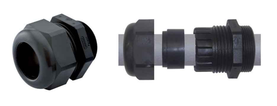
Cable glands are the suggested means of cable entry for the power and I/O cables. It is suggested to use a corrosion-resistant material for the cable gland. The cable gland should be the correct size such that it can pass the RJ45 Ethernet connectors or power cables and still cinch down on the cable and provide a seal. A suggested size is PG13 or M20. The cable gland is not a Cisco product and Cisco does not endorse any specific third-party cable gland. Figure 9 shows the placement of cable glands on the access point.

Power Wires and Tie Downs
Figure 10 shows how to connect DC power wires. The green wire on the left is grounded to the chassis. The red wire on the right side is the positive DC wire. The black wire in the middle is the negative DC wire. Appropriate American Wire Gauge (AWG) and temperature range for the wire needs to be selected for the application.

Figure 11 shows an example of a third-party enclosure with a ESW-6300 mounted inside. Cable ties are wrapped around a cable tie block in order to keep the optional front heatsinks available for use. This may not be the most optimal cable management in every case.
Suggested Parts
NOTE AND DISCLAIMER: The following parts, outlined in Table 3, are not mandatory in terms of type or manufacturer. Third-party manufacturers and part numbers are mentioned only as engineering references. Use of the third-party parts specified in this document is not required by Cisco, nor are these parts specifically recommended over any competitive equivalent. Alternate vendors are available. Cisco does not provide support for any third-party product.
|
Num |
Qty |
Item |
Description |
|---|---|---|---|
|
1 |
1 |
Enclosure |
Integra Traditional High Impact Polycarbonate hinged enclosure with opaque cover. (IP66/68) (Part # H12104H-6P) |
|
2 |
4 |
N connector |
Amphenol RF N-Type Straight Clamp Jack for RG-174, RG-316, LMR-100 Bulkhead (Part # 172223) *should be purchased pre-assembled to Items 3 and 4 |
|
3 |
4 |
RF cable |
Times Microwave LMR-100A Flexible Low Loss Communications Coax (Part # LMR-100A)
|
|
4 |
4 |
SMA connector |
Amphenol RF SMA Plug Right Angle Crimp Plug (Part # 132123)
|
|
5 |
3 |
Cable gland |
PG13 Gland. SealCon (Part # CD13AR-RV)
Or,
|
|
6 |
2 |
Cable tie mount |
Essentra Components: MFTH-2-01A-RT-M, for use with .09 inch zip ties |
|
7 |
4 |
#6 screw |
18-8 Stainless Steel #6-32 ½ inch long screws from McMaster (Part # 91772A148)
|
|
8 |
4 |
#6 split lock |
18-8 Stainless Steel Split Lock Washer for #6 Screw from McMaster (Part # 92146A540) |
|
9 |
4 |
#6 washer |
18-8 Stainless Steel Military Spec #6 Washers from McMaster (Part # 90945A715) |
|
Ref |
Ref |
External RF cable |
Times Microwave LMR-400 or LMR-600 Flexible Low Loss Communications Coax (Part # LMR-400 or LMR-600)
Cisco offers a variety of outdoor coaxial cables with N male connectors. For more information, visit: Cisco Industrial Routers and Industrial Wireless Access Points Antenna Guide |
|
Ref |
Ref |
Lightning arrestor |
Lightning Arrestor (Cisco CGR-LA-NF-NF= or Cisco CGR-LA-NM-NF=)
Datasheet: see Lightning Arrestor for the Cisco 1240 Connected Grid Router Installation instructions: see Cisco Lightning Arrestors section in Connected Grid Antennas Installation Guide |
|
Ref |
Ref |
Punch tool (N-Type) |
Punch Tool for N-Connector referenced in Item 2 Z-Tech: u2D-06400546 |
Access Point Specifications
Technical Specifications
For detailed specifications, refer to the Cisco Catalyst ESW-6300 Embedded Services Access Point data sheet at:
Power Consumption Budget
The following table lists the power consumption budget for the ESW-6300 access point.
|
Element |
Absolute Max Power (Watts) |
||
|---|---|---|---|
|
Total power budget when using DC power source (44-57VDC) |
19.7 |
||
|
Optional components |
|||
|
2 clients of 802.3af (PoE) connected |
30.8 |
||
|
1 client of 802.3at (PoE+) connected |
30.0 |
||
|
Fiber used as backhaul |
1.2 |
||
|
USB 2.0/3.0 add-on module connected |
4.5 |
||
|
Total Power Consumption |
|||
|
Total power consumption when DC powered (44-57VDC) |
56.2 |
||
|
|||
Canada Regulatory Information
IC ID
IC: 2461N-ESW6300
HVIN: 68-102256-01
Canadian Compliance Statement
This device contains license-exempt transmitter(s)/receiver(s) that comply with Innovation, Science, and Development Canada’s license-exempt RSS(s). Operation is subject to the following two conditions:
-
This device may not cause interference.
-
This device must accept any interference, including interference that may cause undesired operation of this device.
Le présent appareil est conforme aux CNR d'Innovation, Sciences et Développement économique Canada applicables aux appareils radio exempts de licence. L'exploitation est autorisée aux deux conditions suivantes:
-
L’appareil ne doit pas produier de brouillage.
-
L’utilisateur de l'appareil doit accepter tout brouillage radioélectrique subi, même si le brouillage est susceptible d'en compromettre le fonctionnement.
Maximum Permissible Exposure
This device has been evaluated for RF exposure for humans in reference to ANSI C 95.1 (American National Standards Institute) limits. The evaluation was based on RSS-102 Rev 5.
ESW-6300-CON - To maintain compliance, the minimum separation distance for antennas that have 8 dBi to 14 dBi gain, is 23.6 inches (60 cm) from general bystanders.
Ce device a été évalué pour l'exposition aux RF pour les humains en référence à la norme ANSI C 95.1 (American National Standards Institute) limites. L'évaluation a été basée sur RSS-102 Rev 2.
ESW-6300-CON - La distance minimale de séparation de l'antenne de toute personne jusqu'à 8 dBi et 23.6" (60 cm) pour les gains d'antenne de 14 dBi pour assurer le respect.
Allowed Antennas
The radio transmitter IC-ID 2461N-ESW6300 has been approved by Innovation, Science, and Economic Development Canada to operate with the antenna types listed below, with the maximum permissible gain indicated. Antenna types not included in this list that have a gain greater than the maximum gain indicated for any type listed are strictly prohibited for use with this device.
|
Antenna |
Frequency Band |
Peak Gain |
Antenna Type |
|---|---|---|---|
|
AIR-ANT2547V-N |
Dual-band |
2.4 GHz: 4 dBi; 5 GHz: 7 dBi |
Omnidirectional |
|
AIR-ANT2547VG-N |
Dual-band |
2.4 GHz: 4 dBi; 5 GHz: 7 dBi |
Omnidirectional |
|
AIR-ANT2547V-N-HZ |
Dual-band |
2.4 GHz: 4 dBi; 5 GHz: 7 dBi |
Omnidirectional |
|
AIR-ANT2568VG-N |
Dual-band |
2.4 GHz: 6 dBi; 5 GHz: 8 dBi |
Omnidirectional |
|
AIR-ANT2513P4M-N |
Dual-band |
13 dBi |
Directional, 4 port |
|
AIR-ANT2450V-N-HZ |
2.4 GHz |
5 dBi |
Omnidirectional |
|
AIR-ANT2450VG-N |
2.4 GHz |
5 dBi |
Omnidirectional |
|
AIR-ANT2450HG-N |
2.4 GHz |
5 dBi |
Omnidirectional |
|
AIR-ANT2480V-N |
2.4 GHz |
8 dBi |
Omnidirectional |
|
AIR-ANT2413P2M-N |
2.4 GHz |
13 dBi |
Directional, 2 port |
|
AIR-ANT5150VG-N |
5 GHz |
5 dBi |
Omnidirectional |
|
AIR-ANT5150HG-N |
5 GHz |
5 dBi |
Omnidirectional |
|
AIR-ANT5180VG-N |
5 GHz |
8 dBi |
Omnidirectional |
|
AIR-ANT5114P2M-N |
5 GHz |
13 dBi |
Directional, 2 port |
Notice of Professional Installation
This device is for professional installation only.
 Feedback