Cisco Power Injector IW-PWRINJ-60RGDMG= Installation Guide
This document describes the Cisco Power Injector IW-PWRINJ-60RGDMG= (referred to as the power injector in this document) and provides instructions for mounting them.
Product Overview
The IW-PWRINJ-60RGDMG= power injector is powered by a single-phase AC voltage input in the range of 90VAC to 264VAC, providing a maximum output of power at a nominal DC Voltage on the appropriate four data pairs of the output RJ45 connector. The power injector meets the requirements of IEEE 802.3bt as a PSE. It can accept 10/100/1000/2500/5000/10000 Base-T traffic on the input and output RJ45 connectors and pass through these signals between the network and the access point.
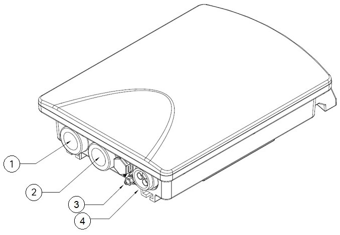
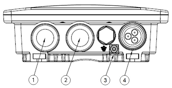
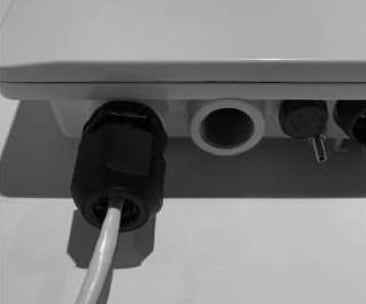
The following figure shows the ports and AC outlet arrangement.
|
1 |
Data and PoE Out RJ45 |
3 |
Ground lug |
|
2 |
Data only RJ45 |
4 |
AC input |
Unpacking the Power Injector
The typical power injector package contains the following items:
-
Power injector
-
AC power plug
-
Two Liquid Tight Cord Grips (LTCG) for RJ45 ports
 Note |
The power injector does not include an AC power cable in the package. Refer to the requirements below for the cable specification and termination instructions. |
If any item is missing or damaged, contact your Cisco representative or reseller.
Additional Requirements
Use the power cord to supply power for the injector. If you install the access point in an environmental air space such as above a suspended ceiling, check national and local safety codes to make sure that the Ethernet cable you connect to the unit meets applicable standards.
Note |
Only qualified and trained service personnel (in accordance with IEC62368 and AS/NZS 3260) should install, replace, or service the equipment. Install the system in accordance with Country, National or to the U.S. National Electric Code if you are in the United States. |
-
The building facilities in which the product will be used must provide Isolation to the main AC Input connector. This connection requires a fuse or circuit breaker no larger than 20A for 120 VAC (U.S.A.) or 16A, 230 VAC (international). The building facilities must protect the power injector from over current or short-circuits.
-
The power injector enclosure is IP67 tested which provides degrees of protection against access to hazardous parts, dust and against ingress of water.
-
The power injector enclosure must be mounted vertically handle up position for wall mounting option.
-
The power injector enclosure has 2 threaded (M20x1.5) openings to accommodate Liquid Tight Cord Grip LTCG (provided) and one watertight AC input socket.
-
The power injector comes with an AC input plug for connecting with the AC power cord. The AC power cord 3 wire or cable must be SJTOO type or better cord 3*18AWG, 5-15P plug and EP030-2224-01 coupler or in accordance with Country, National Electric Code.
-
The power injector consists of Data & Power ports. The ports provide TNV-1 outputs. The ports use RJ-45 data sockets. Do not connect telephone cables into these ports. Only RJ-45 data cables with waterproof or watertight connections may be connected to these sockets.
-
To prevent the power injector from overheating, do not operate the product in an area that exceeds the maximum recommended ambient temperature of -40 ºC to +65 ºC.
-
Do not work on the power injector or connect or disconnect cables, during periods of lightning activity.
-
The AC connector wire combination must be accessible at all times, as it serves as the main disconnect device to the product.
-
Before servicing the product, always disconnect the product from its AC source.
-
Equipment is for Pollution degree 2 Environment.
-
Disposal of this product should abide by all appropriate National laws and regulations.
Technical Specifications
This table lists specifications for the power injectors:
|
Specification |
IW-PWRINJ-60RGDMG= |
||
|---|---|---|---|
|
Input-voltage range and frequency |
AC input: 100-240V, 50-60Hz (nominal) |
||
|
Output voltage and current |
|
||
|
Physical specification |
Dimensions (L x W x H): 246 mm x 170 mm x 58.5 mm
Weight: 4.8 lbs |
||
|
Operating temperature |
-40°C to +70°C, Power derating of 60W @ 70 ⁰C and 65W @ 65 ⁰C |
||
|
Non-operating temperature |
-40°C to +85°C |
||
|
Humidity |
Operating: 10% to 90%, non-condensing Non-operating: 10% to 95%, non-condensing IP67 rated for outdoor application Type 4X |
||
|
Thermal shock |
Operating: -40°C to +70°C. Power derating of 60W @ 70°C and 65W @ 65°C. Non-operating: -40°C to +85°C. |
||
|
Altitude |
Operating altitude: 500 to 17,000 feet from sea level Non-operating altitude: -1,000 to 30,000 feet from sea level |
||
|
Reliability |
MTBF: 300,000 hrs @ 40ºC |
||
|
Regulatory Compliance |
IEEE 802.3 bt, China RoHS Compliant, WEEE Compliant, CE Compliant |
Installing the Power Injector
Follow these steps to install the power injector:
Procedure
|
Step 1 |
The power injector is packaged with two Liquid Tight Cord Grips (LTCG) for RJ45 ports, and one AC power plug for AC power cord assembly. Locate the 3-pin female cable end. 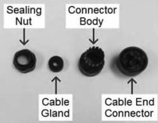
|
|
Step 2 |
Prepare line cord or AC Mains hardwire 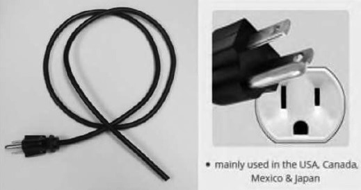
|
|
Step 3 |
Slide the sealing nut (1) and cable gland (2) over the cable. 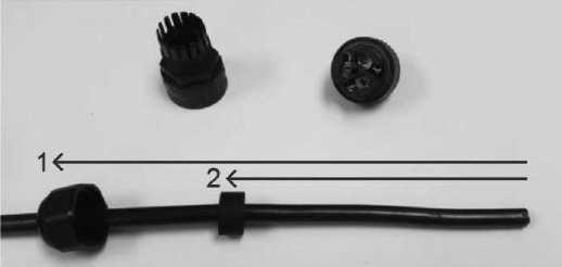
|
|
Step 4 |
If there is an outer jacket of cord, strip approximately 25mm (+/- 1mm) from the end. 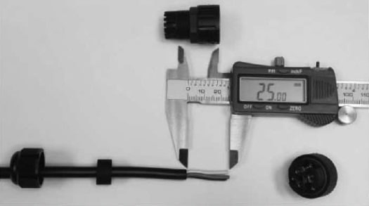
|
|
Step 5 |
Install the connector body and strip each wire approximately 8mm (+/- 1mm) from the end. 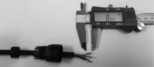
|
|
Step 6 |
It is recommended (if possible) to prevent fraying of wires to tin each wire with solder. 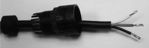
|
|
Step 7 |
Insert the wires to proper location to cable end. 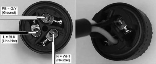
|
|
Step 8 |
Screw the cable end into the connector body and push the cable gland into the connector body. 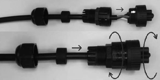
|
|
Step 9 |
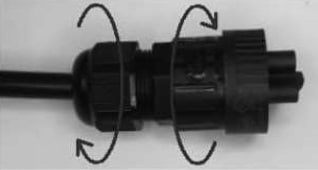
Screw the sealing nut into the connector body. 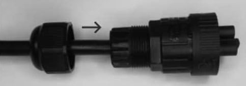
|
|
Step 10 |
AC cord is assembled. 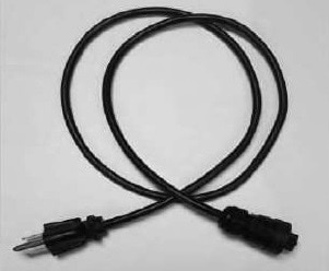
|
|
Step 11 |
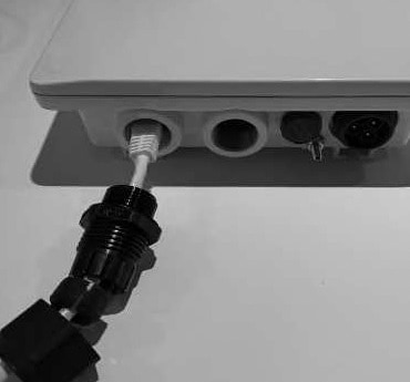
Apply the Liquid Tight Cord Grips (LTCG) to the RJ45 Cable. The LTCG consists of a sealing nut, a split gland, and a body. 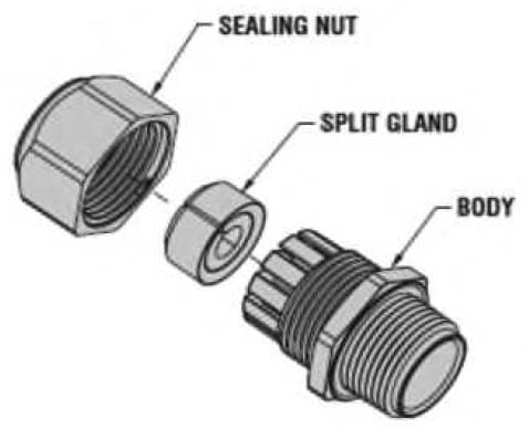
|
|
Step 12 |
Pass the cable termination through the sealing nut, apply the split gland to the cable, and insert it into the LTCG body. 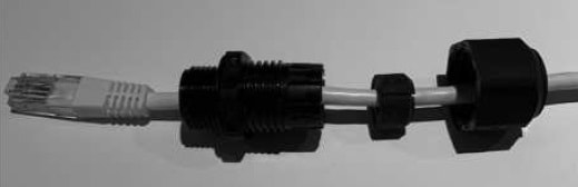
|
|
Step 13 |
(Optional) To enable waterproof operation better, it is recommended that you use Teflon tape to cover the threads before installation. You may also wish to use silicon sealant to acheive further protection from ingress of liquid. |
|
Step 14 |
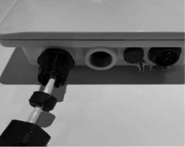
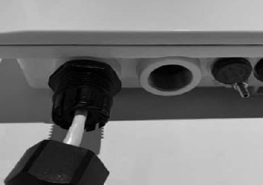
Connect the RJ45 Cable to the power injector.
|
|
Step 15 |
Use the same RJ45 cable connection procedure for other port connection. 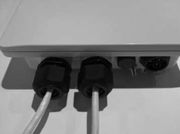
|
|
Step 16 |
Insert the AC cable assembly into the AC input socket of the power injector and tighten the mount ring. 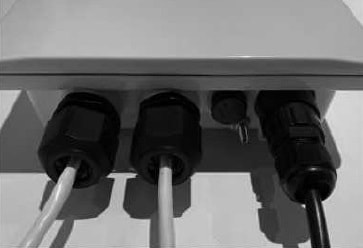
|
Mounting Instructions
You can mount the power injector to flat surfaces or a pole.
Flat Surface Mounting
Following these steps to mount the power injector on the flat surface:
Procedure
|
Step 1 |
Mark the hole locations using the following diagram as a template. 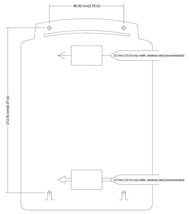
|
|
Step 2 |
Use 4mm (#8) max size screws, not supplied. Use hardware appropriate for mounting surface. |
|
Step 3 |
Install lower 2 screws, leaving screw 3mm (1/8 in) from flush to allow unit to slide onto screws. |
|
Step 4 |
Slide the unit onto lower screws. |
|
Step 5 |
Install upper 2 screws through holes in handle. |
Pole Mounting
Follow these steps to mount the power injector on a pole.
Procedure
|
Step 1 |
Use 12.7mm (1/2 in) max strap width. |
|
Step 2 |
Install stainless steel straps through the slot in the chassis (2 places as shown, not supplied).
|
|
Step 3 |
Wrap the straps around the pole and secure. |
Regulatory Information
The following information is for FCC compliance of Class B devices:
The equipment described in this manual generates and may radiate radio-frequency energy. If it is not installed in accordance with Cisco’s installation instructions, it may cause interference with radio and television reception. This equipment has been tested and found to comply with the limits for a Class B digital device in accordance with the specifications in part 15 of the FCC rules. These specifications are designed to provide reasonable protection against such interference in a residential installation. However, there is no guarantee that interference will not occur in a particular installation.
Modifying the equipment without Cisco’s written authorization may result in the equipment no longer complying with FCC requirements for Class A or Class B digital devices. In that event, your right to use the equipment may be limited by FCC regulations, and you may be required to correct any interference to radio or television communications at your own expense.
You can determine whether your equipment is causing interference by turning it off. If the interference stops, it was probably caused by the Cisco equipment or one of its peripheral devices. If the equipment causes interference to radio or television reception, try to correct the interference by using one or more of the following measures:
-
Turn the television or radio antenna until the interference stops.
-
Move the equipment to one side or the other of the television or radio.
-
Move the equipment farther away from the television or radio.
-
Plug the equipment into an outlet that is on a different circuit from the television or radio. (That is, make certain the equipment and the television or radio are on circuits controlled by different circuit breakers or fuses.)
Modifications to this product not authorized by Cisco Systems, Inc. could void the FCC approval and negate your authority to operate the product.
 Feedback