Table Of Contents
Catalyst 6500 Series Wireless Services Module 2 Installation and Verification Note
Preparing to Install the WiSM2
Obtaining Documentation and Submitting a Service Request
Catalyst 6500 Series Wireless Services Module 2 Installation and Verification Note
Product numbers: WS-SVC-WISM2-1-K9, WS-SVC-WISM2-3-K9, WS-SVC-WISM2-5-K9
This document provides installation procedures for the Catalyst 6500 Series Wireless Services Module 2 (WiSM2) and contains these sections:
•Preparing to Install the WiSM2
•Obtaining Documentation and Submitting a Service Request
Front Panel Description
The WiSM2 front panel (Figure 1) includes six status light-emitting diodes (LEDs), USB and RJ-45 console ports, and USB ports.
Figure 1 WiSM2 Front Panel
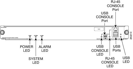
These sections describe the WiSM2 front panel:
Status LEDs
Six status LEDs indicate the operating states of the WiSM2 module. Table 1 describes the status LED operation.
Table 1 Status LED Descriptions
LED Label Color DescriptionSYSTEM
Green/Amber
System Status:
•During system power-up:
–SYSTEM blinks amber.
–ALARM is continuous amber.
•During system boot:
–SYSTEM blinks green.
–ALARM is continuous amber.
•After bootup:
–SYSTEM is continuous green.
–ALARM is off.
•During controller image upgrade:
–SYSTEM is continuous green.
–ALARM blinks green.
•System crash:
–SYSTEM is continuous amber.
–ALARM is off.
•Firmware Error:
–SYSTEM is continuous amber.
–ALARM is continuous amber.
Note Power cycle the controller to clear the firmware error.
•Internal Voltage Error:
–SYSTEM blinks amber.
–ALARM is continuous amber.
•Temperature Error:
–SYSTEM is off.
–ALARM blinks amber.
Note Check for blocked air vents and fans on the chassis.
ALARM
POWER
Green
The POWER LED is green when the module is receiving power and is off when power is removed.
CONSOLE
USB CONSOLE LED
RJ-45 CONSOLE LED
Green
USB console port LED status:
•Off—Not active.
•Solid green—Indicates the active aux port.
Note When this LED is on, the RJ-45 console port LED is off.
Green
RJ-45 console port LED status:
•Off—Not active.
•Solid green—Indicates the active console port.
Note When this LED is on, the USB console (aux) port LED is off.
USB LED
(USB 0 and 1)
Green/Amber
USB 0/USB 1 OIR indication/notification:
•Off—Not active
•Solid green—Active and enabled.
•Solid amber—Active with failure.
Note For LED descriptions, see the "OIR LED Descriptions" section.
OIR LED Descriptions
There is a consistent CLI-based Online Insertion and Removal (OIR) notification scheme for all slots that support "Nonsurprise" OIR. Table 2 describes the OIR LED indicator for these slots. There is no special LED indication for module insertion. The PSU and Fan Tray supports surprise OIR and does not have a special CLI or LED indication.
Table 2 OIR LED Descriptions
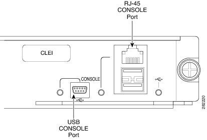
CONSOLE Ports
There are two types of CONSOLE ports, the RJ-45 console port and the USB console port. See Figure 2 for the location of the CONSOLE ports.
Note On the front panel of the WiSM2, both ports have one CONSOLE label.
The WiSM2 offers both an RJ-45 serial console interface and a USB console interface. Only one of the console ports can be active at a time; the USB console takes priority over the RJ-45 console by default. When a USB Host (PC) is plugged into the USB console port, the hardware automatically switches over to use the USB console. When the USB cable is removed or the PC deactivates the USB connection, the hardware automatically switches to the RJ-45 console interface.
Note Only a PC that has the necessary USB console device driver causes the USB console to become active. Plugging in a PC that does not have the USB console driver support does not cause a switchover.
When using the USB console port for operation with Microsoft Windows, you must install the Cisco Windows USB Console Driver on any PC that is connected to the console port. If it is not installed, prompts guide you through a simple installation process. To download the latest Cisco Windows USB Console Driver, follow these steps:
Step 1 Go to the Software download page at
http://www.cisco.com/cisco/software/navigator.htmlStep 2 Click Wireless.
Step 3 Click Wireless LAN Controllers.
Step 4 Click Integrated Controllers and Controller Modules.
Step 5 Click Cisco Wireless Services Module 2 (WiSM2).
Step 6 Click USB Console Software and follow the download instructions.
Note The USB console driver also works on Linux and MacOS Hosts. See the notes listed inside the Cisco Windows USB Console driver package for installation details.
There is an LED adjacent to the USB CONSOLE connector and an LED next to the RJ-45 CONSOLE connector. One of these two LEDs will light to indicate the active console. For LED information see the "Status LEDs" section. Both ports are described in this section.
Figure 2 USB CONSOLE Port and RJ-45 CONSOLE Port
RJ-45 CONSOLE Port
The RJ-45 CONSOLE port is used for the initial configuration of the WiSM2. The port is a single RS232 port used for customer console port access and is connected to the control plane UART serial interface. The console port pinouts on the RJ-45 connector, is shown in Table 3. At initial power-up, the software should set the default baud rate to 9600.
Table 3 Console RJ-45 Port Pinouts
Pin Number Console/Aux Port (RJ-45) Signal Direction1
NC
2
TXD-DBG
Output
3
TXD
Output
4
GND
5
GND
6
RXD
Input
7
RXD-DBG
Input
8
NC
Note The initial WiSM2 configuration must be made through a direct connection to the RJ-45 CONSOLE port. After the initial configurations, you can make an Secure Shell (SSH) or Telnet connection to the module to further configure the module.
USB Console Port
The USB Console port is a Type B interface that allows an interface to the console from a PC using a Type A to Type B cable. The connector is a mini Type B. The Type B connector supports a USB interface and outputs a standard serial (RS232) stream between the RJ-45 console stream and the USB Console stream. Only one USB Console port is active at a time, either the RJ-45 or USB. The controller detects if a connection is made to the USB-Console and deactivates the RJ-45 console. The pinouts of the mini Type B is shown in Table 4.
Table 4 USB CONSOLE Type B Port Pinouts
Note In this document, the term "Mini Type B" is used to indicate only a 5-Pin Mini Type B connector and cable. There is a 4 Pin Mini Type B connector (and cable) as well, but the two are not compatible.
USB Ports
There are two Type-A external USB ports. Each port is fully complaint per the USB 2.0 specification, and support low (1 Mb/s), full (12 Mb/s), and high speed (480 Mb/s) operation. As per the USB 2.0 specification, these ports are backwards compatible with USB1.1 devices.
The dual-port USB receptacle is shielded and the shield is tied to chassis ground. The Type-A receptacle can only accept Type-A plugs. Mini-A and Mini-AB plugs are not supported. The Type A connector pinouts are shown in Table 5.
Table 5 USB Ports Type A Connector Pinouts
Power Requirements
The WiSM2 requires 225 W for operation. Make sure that your chassis can provide this power.
Note All Catalyst 6500 chassis (except the Catalyst 6503) require the fan tray 2 module, which requires the 2500 W power supply for proper operation. For planning purposes, be aware that the 2500 W power supply requires a 20 A input power circuit with a NEMA plug.
You can use the show power command to view power details for your installation, including the system power available and power statistics for installed power supplies and cards.
System Requirements
Before you install the WiSM2 into the Catalyst 6500 series switch, see the Release Notes for Catalyst 6500 Series Wireless LAN Services Module Software Release to make sure that the switch meets the hardware and software requirements.
Safety Overview
Safety warnings appear throughout this publication in procedures that, if performed incorrectly, may harm you. A warning symbol precedes each warning statement.
Warning Only trained and qualified personnel should be allowed to install, replace, or service this equipment. Statement 1030
Warning Hazardous voltage or energy is present on the backplane when the system is operating. Use caution when servicing. Statement 1034
Warning Blank faceplates and cover panels serve three important functions: they prevent exposure to hazardous voltages and currents inside the chassis; they contain electromagnetic interference (EMI) that might disrupt other equipment; and they direct the flow of cooling air through the chassis. Do not operate the system unless all cards, faceplates, front covers, and rear covers are in place. Statement 1029
Warning This unit is intended for installation in restricted access areas. A restricted access area can be accessed only through the use of a special tool, lock and key, or other means of security. Statement 1017
Preparing to Install the WiSM2
Note Before installing the WiSM2, you must install the Catalyst 6500 series switch chassis and at least one supervisor engine. For information on installing the switch chassis, see the Catalyst 6500 Series Switch Installation Guide.
Before installing the WiSM2, make sure that the following items are available:
•Catalyst 6500 series switch chassis
•Management station that is available through a console connection to perform configuration tasks
Required Tools
Warning Only trained and qualified personnel should be allowed to install, replace, or service this equipment. Statement 1030
These tools are required to install the WiSM2 into the Catalyst 6500 series switch:
•Flat-blade screwdriver
•Wrist strap or other grounding device
•Antistatic mat or antistatic foam
Installing the WiSM2
Note Before installing the WiSM2, you must install the Catalyst 6500 series switch chassis and at least one supervisor engine. For information on installing the switch chassis, see the Catalyst 6500 Series Switch Installation Guide.
This section describes how to install the WiSM2 into the Catalyst 6500 series switch.
Note All modules, including the supervisor engine (if you have redundant supervisor engines), support hot swapping. You can add, replace, or remove modules without interrupting the system power or causing other software or interfaces to shut down. For more information about hot-swapping modules, see the Catalyst 6500 Series Switch Module Installation Guide.
Warning During this procedure, wear grounding wrist straps to avoid ESD damage to the card. Do not directly touch the backplane with your hand or any metal tool, or you could shock yourself. Statement 94
To install the WiSM2 into the Catalyst 6500 series switch, follow these steps:
Step 1 Make sure that you take the necessary precautions to prevent ESD damage.
Step 2 Choose a slot for the WiSM2. See Figure 3 for the slot numbers on a Catalyst 6500 series switch.
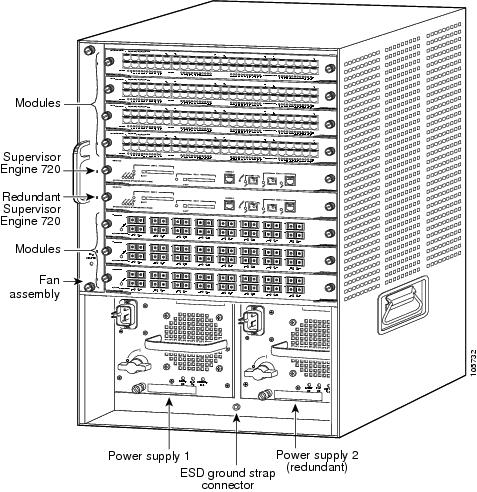
Figure 3 Slot Numbers on Catalyst 6500 Series Switches
Step 3 Check that there is enough clearance to accommodate any interface equipment that you will be connecting directly to the supervisor engine or switching module ports.
Note If possible, place switching modules between the empty slots that contain only switching-module filler plates (Cisco part number 800-00292-01).
Warning Blank faceplates and cover panels serve three important functions: they prevent exposure to hazardous voltages and currents inside the chassis; they contain electromagnetic interference (EMI) that might disrupt other equipment; and they direct the flow of cooling air through the chassis. Do not operate the system unless all cards, faceplates, front covers, and rear covers are in place. Statement 1029
Step 4 Loosen the captive installation screws that secure the switching module filler plate (or an existing switching module) to the desired slot.
Step 5 Remove the switching module filler plate (or an existing switching module).
Step 6 Hold the handle of the WiSM2 with one hand, and place your other hand under the carrier support. Do not touch the printed circuit boards or connector pins.
Step 7 Place the WiSM2 in the slot. Align the notch on the sides of the switching module carrier with the groove in the slot. (See Figure 4.)
Step 8 Keep the WiSM2 at a 90-degree angle to the backplane and carefully slide the WiSM2 into the slot until the switching module faceplate contacts the ejector levers. (See Figure 5.)
Step 9 Using the thumb and forefinger of each hand, simultaneously push in the left and right levers to fully seat the WiSM2 in the backplane connector.
Caution Always use the ejector levers when installing or removing the WiSM2. A module that is partially seated in the backplane will cause the system to halt and subsequently crash.
Note If you perform a hot swap, the console displays the message "Module n has been inserted." This message does not appear if you are connected to the Catalyst 6500 series switch through a Telnet session.
Step 10 Use a screwdriver to tighten the captive installation screws on the left and right ends of the WiSM2.
Figure 4 Installing Modules in the Catalyst 6500 Series Switch
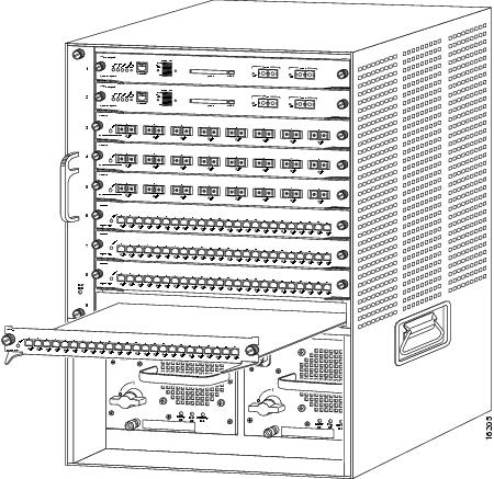
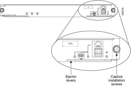
Figure 5 Ejector Levers and Captive Installation Screws
This completes the WiSM2 installation procedure.
Verifying the Installation
When you install the WiSM2 into the Catalyst 6500 series switch, the module goes through a boot sequence that requires no intervention. At the successful conclusion of the boot sequence, the green STATUS LED lights and remains on. If the STATUS LED is yellow, see Table 1 to determine the status of the module.
Enter the show module command to verify the installation:
Router# show module
sjc14-13a-wnbu-sboxsw1#sh moduleMod Ports Card Type Model Serial No.--- ----- -------------------------------------- ------------------ -----------1 4 WiSM 2 WLAN Service Module WS-SVC-WISM2-K9 SAL1421JDFL2 48 48 port 10/100 mb RJ45 WS-X6348-RJ-45 SAL0725F9PR3 8 CEF720 8 port 10GE with DFC WS-X6708-10GE SAL1227W24Z5 2 Supervisor Engine 720 (Active) WS-SUP720-3B SAD0923089R...Mod Online Diag Status--- -------------------1 Pass2 Pass3 Pass5 PassRouter#Removing the WiSM2
This section describes how to remove the WiSM2 from the Catalyst 6500 series switch.
Caution Do not remove the WiSM2 from the switch until the module has shut down completely and the STATUS LED is orange or off. You can damage the module if you remove it from the switch before it completely shuts down.
Warning During this procedure, wear grounding wrist straps to avoid ESD damage to the card. Do not directly touch the backplane with your hand or any metal tool, or you could shock yourself. Statement 94
To remove the WiSM2, perform these steps:
Step 1 Shut down the module by one of these methods:
•In privileged mode from the router prompt, enter the hw-mod module mod shutdown command.
Note If you enter this command to shut down the module, you must enter the following commands in global configuration mode to restart (power down, and then power up) the module:
Router#
no power enable module mod
Router# power enable module mod
•If the module does not respond to any commands, press the SHUTDOWN button located on the front panel of the module.
Note Shutdown may require several minutes.
Step 2 Verify that the WiSM2 shuts down. Do not remove the module from the switch until the POWER LED is off.
Step 3 Use a screwdriver to loosen the captive installation screws at the left and right sides of the module.
Step 4 Grasp the left and right ejector levers. Simultaneously, pull the left lever to the left and the right lever to the right to release the module from the backplane connector.
Step 5 As you pull the module out of the slot, place one hand under the carrier to support it. Avoid touching the module itself.
Step 6 Carefully pull the module straight out of the slot, keeping one hand under the carrier to guide it. Keep the module at a 90-degree orientation to the backplane (horizontal to the floor).
Step 7 Place the removed module on an antistatic mat or antistatic foam.
Warning Blank faceplates and cover panels serve three important functions: they prevent exposure to hazardous voltages and currents inside the chassis; they contain electromagnetic interference (EMI) that might disrupt other equipment; and they direct the flow of cooling air through the chassis. Do not operate the system unless all cards, faceplates, front covers, and rear covers are in place. Statement 1029
Step 8 If the slot is to remain empty, install a module filler plate to keep dust out of the chassis and to maintain proper airflow through the module compartment.
Related Documentation
For more detailed installation and configuration information, see the following publications:
•Release Notes for Catalyst 6500 Series WiSM2
•Catalyst 6500 Series Switch and Cisco 7600 Series Router Wireless Services Module Installation and Verification Note
•Catalyst 6500 Series WebVPN Services Module Installation and Verification Note
•Catalyst 6500 Series Switch Cisco IOS Software Configuration Guide
•Catalyst 6500 Series Switch Cisco IOS Command Reference
•Regulatory Compliance and Safety Information for the Catalyst 6500 Series Switches
•Site Preparation and Safety Guide
Obtaining Documentation and Submitting a Service Request
For information on obtaining documentation, submitting a service request, and gathering additional information, see the monthly What's New in Cisco Product Documentation, which also lists all new and revised Cisco technical documentation, at:
http://www.cisco.com/en/US/docs/general/whatsnew/whatsnew.html
Subscribe to the What's New in Cisco Product Documentation as a Really Simple Syndication (RSS) feed and set content to be delivered directly to your desktop using a reader application. The RSS feeds are a free service and Cisco currently supports RSS Version 2.0.
Cisco and the Cisco Logo are trademarks of Cisco Systems, Inc. and/or its affiliates in the U.S. and other countries. A listing of Cisco's trademarks can be found at www.cisco.com/go/trademarks. Third party trademarks mentioned are the property of their respective owners. The use of the word partner does not imply a partnership relationship between Cisco and any other company. (1005R)