Client IPv6 Support in C9800 Release 16.10
This document provides information about the theory of operation and configuration for Cisco’s Unified Wireless LAN solution as it pertains to supporting IPv6 clients.
The Infrastructure IPv6 Support in C9800 Release IOS-XE 16.10 and Later, page 19 section of this document provides information about the Infrastructure support for IPv6 protocols in the C9800 controllers in Release IOS-XE 16.10 and above.
IPv6 Wireless Client Connectivity Supported in IOS Release 16.10
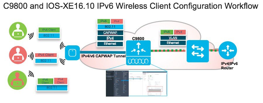
The IPv6 feature set within the Cisco C9800 software IOS-XE release version 16.10 allows the wireless network to support IPv4, Dual-Stack, and IPv6-only clients on the same wireless network. The overall goal for the addition of IPv6 client support to the Cisco SDA is to maintain feature parity between IPv4 and IPv6 clients including mobility, security, guest access, quality of service, and endpoint visibility.
A client can have multiple IPv6 addresses. For each IPv6 prefix received, the client generates an IPv6 address based on its MAC address, and one or more temporary IPv6 addresses, which are also globally routable. When multiple IPv6 prefixes are present, the client may have more addresses. In C9800 rel 16.10, we support maximum 8 IPv6 addresses per wireless client. This allows IPv6 clients to have a link-local, SLAAC address, DHCPv6 address, and even addresses in alternative prefixes to be on a single interface.
Every IPv6 enabled interface must contain at least, 1 Loopback and 1 Link-Local address. Optionally, every interface can have multiple Unique-Local and Global IPv6 addresses.
Solution Components
-
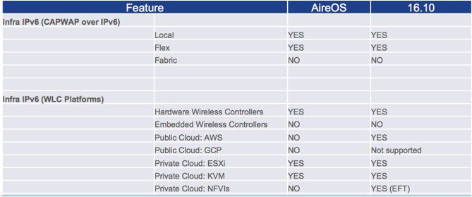
Wireless controllers supported in the release 16.10 are all forms of the Virtual C9800-CL, HW Appliance C9800 and C9800-CL
-
Cisco APs supported in IOS-XE 16.10 - 2700, 3700,1800, 2800, 3800, 4800 series
-
Cisco Outdoor APs supported in rel 16.10 – 1540, 1560 and 1570 (IPv4 only) series
 Note |
The following IPv6 features are not supported in IOS-XE release 16.10:
|
Prerequisites for Wireless IPv6 Client Connectivity
To enable wireless IPv6 client connectivity, the underlying wired network must support IPv6 routing and an address assignment mechanism such as SLAAC or DHCPv6. The wireless controller must have L2 adjacency to the IPv6 router, and the VLAN must be tagged when entering the controller interfaces.
IPv6 is an important networking feature on wireless controllers when we extend IPv6 support from wired clients to wireless clients. A major IPv6 deployment method is the Stateless Address Autoconfiguration (SLAAC), which allows the clients to generate their own IPv6 addresses and ensures compliance to the network addressing rules. The SLAAC method utilizes the IPv6 Neighbor Discovery Protocol (NDP) to distribute the IPv6 network prefix information to clients and accommodate the detection for potential address conflicts. When address conflict does not exist, the NDP protocol facilitates client IPv6 address learning in the network.
SLAAC and NDP work on a VLAN basis. The IPv6 prefix from the router is specific to the client VLAN and it is distributed in the network only through that VLAN. The technical challenge for wireless clients to acquire IPv6 addresses through SLAAC and NDP is that VLAN is not a native concept in the wireless network between the controller and the wireless clients. Transportation of VLAN specific traffic over the wireless network requires special handling. The wireless controller needs to track the existence and location of wireless clients on a given VLAN in order to deliver the VLAN specific packets to the clients. The problem becomes more complicated when client mobility is present. In addition to tracking the local clients by their AP associations, the wireless controller also needs to track the roamed clients by their foreign controller attachments.
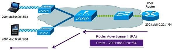
As mentioned above, the most common method for IPv6 client address assignment is Stateless Address Auto Configuration (SLAAC). SLAAC provides simple plug and play connectivity where clients self-assign an address based on the IPv6 prefix. This process is achieved by the IPv6 router sending out periodic Router Advertisement messages which inform the client of the IPv6 prefix in use (the first 64 bits) and of the IPv6 default gateway. From that point, clients can generate the remaining 64 bits of their IPv6 address based on either the MAC address of the adapter or randomly. Duplicate address detection is performed by IPv6 clients to ensure random addresses that are picked do not collide with other clients. The address of the router sending advertisements is used as the default gateway for the client.
The Stateless Address Autoconfiguration (SLAAC) is a newer IPv6 address configuration method other than the conventional DHCP method. DHCP is a stateful mechanism, where the server keeps the individual client addresses to ensure non-conflicting address assignments. SLAAC is stateless in the sense that the router does not track individual addresses. Rather, it is only responsible for advertising the address prefix. It is the client’s decision to generate the IPv6 address conforming to the prefix. The address is formed by combining the prefix and a suffix mapped from the client MAC address. To protect the address uniqueness, the Neighbor Discovery Protocol (NDP) is employed to detect potential address conflicts.
The following configuration example from a Cisco-capable IPv6 router has the necessary commands to enable SLAAC addressing and router advertisements:
interface Vlan20 description IPv6-SLAAC
ip address 192.168.20.1 255.255.255.0
ipv6 address 2001:DB8:0:20::1/64
ipv6 enable
end
Neighbor Discovery Caching
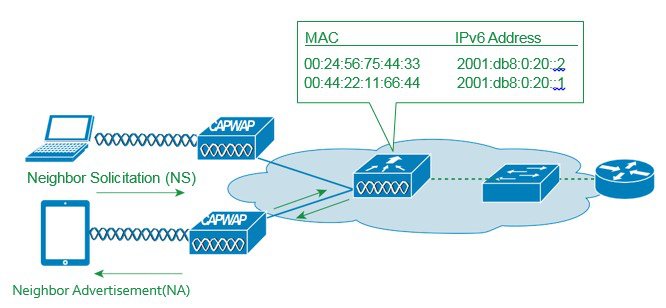
The IPv6 neighbor discovery protocol (NDP) utilizes Neighbor Advertisement (NA) and Neighbor Solicitation (NS) packets in place of ARP to allow IPv6 clients to resolve the MAC address of other clients on the network. The NDP process initially uses multicast addresses to perform address resolution. This process consumes valuable wireless airtime because the multicast addresses are sent.
To increase the efficiency of the NDP process, neighbor discovery caching allows the controller to act as a proxy and responds back to the NS queries that it can support address resolution and duplicate address detection. Neighbor discovery caching is made possible by the underlying neighbor binding table present in the controller. The neighbor binding table keeps track of each IPv6 address and its associated MAC address. When an IPv6 client attempts to resolve another client’s link-layer address, the neighbor solicitation packet is intercepted by the controller that responds back with a neighbor advertisement packet to all the clients in the network segment.
DHCPv6 Address Assignment
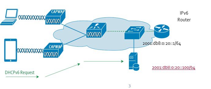
With DHCPv6, the client looks for the DHCPv6 server once it is connected to the network. The Solicit packet is multicast to the network and the client uses its IPv6 link local address as the source address. Any DHCPv6 server replying to the Solicit unicasts the Advertise packet back to the client using the client link local address as the destination. The client replies with a Request packet that is multicast to all servers to select an IPv6 address. Finally, the chosen server responds by unicasting the Reply packet to the client to confirm the IPv6 address.
The use of DHCPv6 is not required for IPv6 client connectivity if SLAAC is already deployed. There are two modes of operation for DHCPv6 called Stateless and Stateful.
The DHCPv6 Stateless mode is used to provide clients with additional network information not available in the router advertisement. This information can include the DNS domain name, DNS server(s), and other vendor-specific options. The following interface configuration example is for an IPv6 router implementing stateless DHCPv6 with SLAAC enabled, see a configuration example below:
interface Vlan20
description IPv6-DHCP-Stateless
ip address 192.168.20.1 255.255.255.0
ipv6 enable
ipv6 address 2001:DB8:0:20::1/64 ipv6 nd other-config-flag
ipv6 dhcp relay destination 2001:DB8:0:20::100
 end
The DHCPv6 Stateful mode operates similar to DHCPv4, that is, it assigns addresses to each client instead of the client generating the address as in SLAAC. The following interface configuration is for an IPv6 router implementing stateful DHCPv6 with SLAAC turned off:
interface Vlan20
description IPv6-DHCP-Stateful
ip address 192.168.20.1 255.255.255.0
ipv6 enable
ipv6 address 2001:DB8:0:20::1/64
ipv6 nd prefix 2001:DB8:0:20::/64 no-advertise ipv6 nd managed-config-flag
ipv6 nd other-config-flag
ipv6 dhcp relay destination 2001:DB8:0:20::100
end
Static IPv6 Address Assignment
In this method, the user configures the client IPv6 address manually. The network learns the client address when the client announces it through an NA packet. Static addressing is simple, but it becomes difficult to use when the user has many clients to configure. It also has the potential problem of address conflict since the user chosen address is not guaranteed to be collision free.
NDP-Neighbor Discovery Protocol
The NDP protocol consists of several ICMPv6 message types that are designed for hosts in a network to find v6 routers, acquire routing information, and resolve address bindings. When used together with SLAAC.
IPv6 NDP packets have 4 types: Router Solicitation (RS), Router Advertisement (RA), Neighbor Solicitation (NS), Neighbor Advertisement (NA).
Router Solicitation
The RS message is ICMPv6 type 133. Hosts inquire the network for routers using this message after being attached to the network. The host uses its link local address as the source and multicasts it to the all-routers address FF02::2, which will reach all the routers in the link local scope. The RS message prompts routers to generate router advertisements quickly.
Router Advertisement
The RA message is ICMPv6 type 134. Routers advertise their presence with network parameters using this message either periodically or in response to a RS message. It carries the IPv6 network prefix to be used by hosts to construct their addresses. The source address in the packet is the router’s link local address. If the RA is solicited by a RS, the destination address is the source address in the invoking RS packet. If it is unsolicited, the destination address is the all-nodes multicast address FF02::1.
Neighbor Solicitation
The NS message is ICMPv6 type 135. Nodes send NS to resolve the link-layer MAC address of a target node while providing their own MAC addresses to the target at the same time. NS is multicast when it is used to resolve an address and unicast when it is to verify the reachability of a neighbor node. The source address in NS is the sender’s address except for the duplicate address detection case, where the source address is unspecified since the sender cannot start using its IPv6 address yet. The destination address in NS is the target node address if the sender is verifying the target reachability or the solicited-node multicast address corresponding to the target address.
Neighbor Advertisement
The NA message is ICMPv6 type 136. Nodes send NA in response to NS and also unsolicited NA to propagate node address information in the network. The Solicited flag in the message marks if the NA is solicited by an NS or not. The source address in the message is the sender’s address. For solicited NA, the destination address is the source address in the invoking NS or all-nodes multicast address if the solicitation’s source address is unspecified. For unsolicited NA, the destination is the all-nodes multicast address.
Multicast handling on C9800 IOS-XE 16.10
Multicast traffic for local clients is supported by vC9800 in one of two forms, Multicast-over-Unicast (MoU) or Multicast-over-Multicast (MoM). With MoU, the vC9800 controller unicasts a copy of multicast packet to each AP, while in MoM, the controller only sends one multicast packet out and the network replicates the packet as needed along the multicast tree branches to reach all the APs. Each AP decides individually if it has to forward the packet to any wireless clients based on the client association records. MoU or MoM mode is configurable on the C9800 controller by the admin. When a large number of APs are connected to the controller through an intermediate network, MoM saves the network bandwidth as fewer packets are transported.
Note |
MoU is only supported on Virtual C9800 and for only small template. |
IPv6 Client Mobility
In order to deal with roaming IPv6 clients across controllers, the ICMPv6 messages such as NS, NA, RA, and RS must be dealt with specially to ensure that a client remains on the same Layer 3 network. The configuration for IPv6 mobility is the same as for IPv4 mobility and requires no separate software on the client side to achieve seamless roaming. The only required configuration is the controllers must be part of the same mobility group/domain.
The process of IPv6 client mobility across controllers is as follows:
-
If both controllers have access to the same VLAN the client was originally on, the roam is simply a Layer 2 roaming event where the client record is copied to the new controller and no traffic is tunneled back to the anchor controller.
-
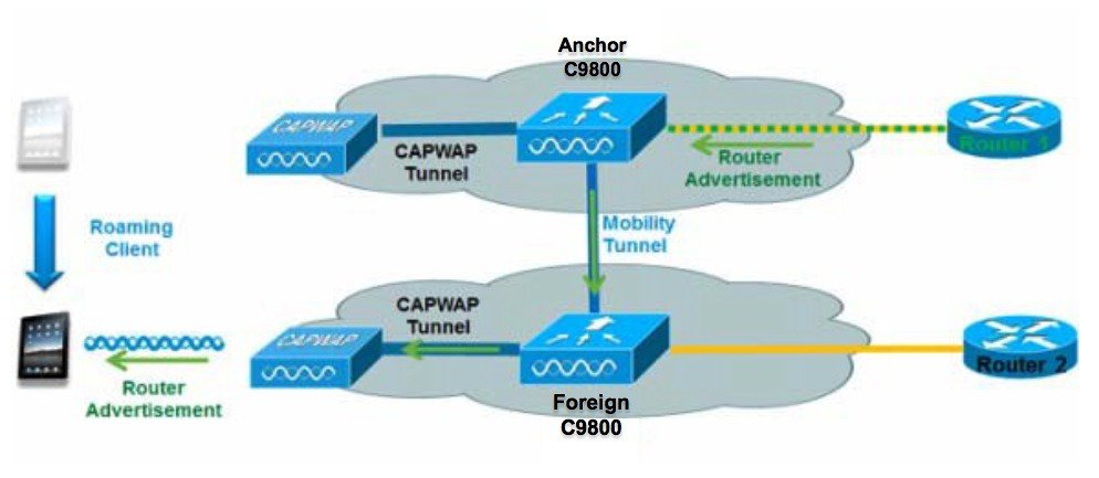
If the second controller does not have access to the original VLAN the client was on, a Layer 3 roaming event will occur, meaning all traffic from the client must be tunneled via the Mobility Tunnel to the anchor controller.
-
In 16.10 deployments, we support CAPWAP encrypted tunnel for IPv6 mobility tunnel.
-
To ensure that the client retains its original IPv6 address, the Router Advertisements from the original VLAN are sent by the anchor controller to the foreign controller where they are delivered to the client using L2 Unicast from the AP.
-
When the roamed client goes to renew its address via DHCPv6 or generate a new address via SLAAC, the Router Solicitation, Neighbor Advertisement, and Neighbor Solicitation packets continue to be tunneled to the original VLAN so that the client receives an IPv6 address that is applicable to that VLAN.
-
In C9800 IOS-XE release 16.10, the RA MGID (M-cast Group ID) and RA Mobility tables are created and maintained inside each controller. Both tables are implemented as process internal data structures. Each controller updates the RA MGID table whenever a client joins or leaves to keep track of the current topology of clients. In mobility scenarios, the anchor controller constructs the RA Mobility table to keep an up-to-date roamed client topology so that the anchor controller knows which foreign controllers need to receive RA packets. Entries are created in this table when the anchor controller sends the handoff message for roamed clients. Entries are deleted at the time the clients roam back to the anchor controller or disassociate from the network. On the foreign controllers, the RA MGID tables are used to deliver RAs to the visiting clients in the same way as the local clients.
On client deletion, the controller cleans up the client from the MGID or mobility table, removes the AP or mobility IFID from the multicast group if the client is the last one using this IFID, and requests AP to delete the client from the MGID list. After the cleanup, the controller will not forward RA packets to the client anymore.
AP maintains a list of MGIDs that it receives from the controller on client associations. MGIDs are mapped statically from the client VLAN IDs. AP has an MGID entry in the list as long as it has any client associated on the statically mapped VLAN. All such clients are recorded in the MGID entry. Since multicast over wireless is not robust, the MGID entry helps AP convert RA multicast packet into unicast packet for each wireless client in the entry. The controller informs AP to remove a client from the MGID entry at time of client deletion.
In the current implementations in IOS-XE 16.10, the RA MGID table is created and maintained within the controller. The requirement is that every VLAN is assigned a unique RA MGID value.
Maximum number of VLANs supported – 4096
MGID range reserved for RA – 8192 to 12287
Number of RA-MGIDs – 8192
Support for Interface Groups
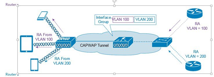
The interface groups feature allows an organization to have a single WLAN with multiple VLANs configured on the controller to permit load balancing of wireless clients across these VLANs. This feature is commonly used to keep IPv4 subnet sizes small while enabling a WLAN to scale to thousands of users across multiple VLANs in the group. To support IPv6 clients with interface groups, no additional configuration is required as the system automatically sends the correct router advertisement to the correct clients via L2 wireless unicast. By unicasting the router advertisement, clients on the same WLAN, but a different VLAN, do not receive the incorrect RA.
Note |
For the reasons, explained above, it is not recommended to mix IPv4 and IPv6 dual stack clients in the same Interface Group. |
First Hop Security for IPv6 Clients
RA Management
When SLAAC is used, RA delivery to wireless clients is important for the clients to construct IPv6 addresses. Clients need to receive RA periodically for two reasons. First, the IPv6 prefix advertised in RA is valid for a period only. Clients expect new RAs before the prefix validity expires. Second, if a new prefix is configured, clients should receive new RAs in order to be informed on the new prefix. For these reasons, RAs should be delivered to both local and roamed clients continuously regardless of client mobility. In local case, RAs are sent to the clients through AP CAPWAP tunnels. In foreign case, RAs are forwarded by the anchor controller to the foreign controllers through mobility tunnels first, and then they are delivered to wireless clients through AP CAPWAP tunnels on the foreign controllers.
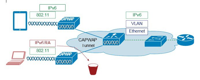
The RA Guard feature increases the security of the IPv6 network by dropping router advertisements coming from wireless clients. Without this feature, misconfigured or malicious IPv6 clients could announce themselves as a router for the network, often with a high priority, which could take precedence over legitimate IPv6 routers.
RA guard is a functionality that protects the system from RA packets that are sent from non-trusted, unauthorized or misconfigured devices. This functionality analyzes the RAs and filters them out based on the device that sent them. By default, RA guard is disabled on C9800 but can be enabled through CLI. Once RA guard is enabled, the RA packets received on the wireless interfaces are dropped. It can be considered as a simple mechanism to prevent wireless clients from advertising themselves as routers on a wireless network.
ND Suppress
Neighbor solicitation to resolve wireless client link-layer address may result in a lot of overhead in the wireless network. In this case, the destination address in NS is the all-node multicast address. Multicasting NS to every wireless client consumes wireless resources heavily. To solve the wireless multicast problem, the controller maintains the wireless client address-to-MAC bindings. The controller can either respond to an NS on behalf of the wireless client or convert the multicast NS into a unicast one to the target client. Both solutions save the wireless resources as the unnecessary delivery to other clients is eliminated.
DHCPv6 Server Guard
The DHCPv6 Server guard feature prevents wireless clients from handing out IPv6 addresses to other wireless clients or wired clients upstream. To prevent DHCPv6 addresses from being handed out, all DHCPv6 advertise packets from wireless clients are dropped. This feature operates on the controller, requires no configuration and is enabled automatically.
IPv6 Source Guard
The IPv6 source guard feature prevents a wireless client spoofing an IPv6 address of another client. This feature is analogous to IPv4 source guard. IPv6 source guard is enabled by default.
IPv6 Access Control Lists
In order to restrict access to certain upstream wired resources or block certain applications, IPv6 Access Control lists can be used to identify traffic and permit or deny it. IPv6 Access Lists support the same options as IPv4 Access Lists including source, destination, source port, and destination port (port ranges are also supported).
Network Resource Efficiency for IPv6 Clients
Neighbor Discovery Caching
The IPv6 neighbor discovery protocol (NDP) utilizes Neighbor Advertisement (NA) and Neighbor Solicitation (NS) packets in place of ARP to allow IPv6 clients to resolve the MAC address of other clients on the network. The NDP process initially uses multicast addresses to perform address resolution. This process consumes valuable wireless airtime because the multicast addresses are sent.
To increase the efficiency of the NDP process, neighbor discovery caching allows the controller to act as a proxy and responds back to the NS queries that it can support address resolution and duplicate address detection. Neighbor discovery caching is made possible by the underlying neighbor binding table present in the controller. The neighbor binding table keeps track of each IPv6 address and its associated MAC address. When an IPv6 client attempts to resolve another client’s link-layer address, the neighbor solicitation packet is intercepted by the controller that responds back with a neighbor advertisement packet to all the clients in the network segment.
Router Advertisement Throttling
Router Advertisement (RA) throttling allows the controller to enforce rate limiting of RAs headed towards the wireless network. By enabling RA throttling, routers that are configured to send RAs frequently (every 3 seconds) can be trimmed back to a minimum frequency that will still maintain IPv6 client connectivity. This allows airtime to be optimized by reducing the number of multicast packets that must be sent. In all cases, if a client sends a Router Solicitation (RS), then an RA will be allowed through the controller and unicast to the requesting client. This is to ensure that new clients or roaming clients are not negatively impacted by RA throttling.
Note |
When RA throttling occurs, only the first IPv6 capable router is allowed through. For networks that have multiple IPv6 prefixes being served by different routers, RA throttling must be disabled. |
IPv6 Router Configuration
The IPv6 router is usually configured on a switch connected to C9800. The client VLAN should be configured on the router with the IPv6 settings. In addition, the physical link between the router and C9800 should allow the client VLAN traffic to pass through. If the router has other links to reach APs, which is possible since APs join C9800 through an intermediate network, the client VLAN should be blocked on these links to avoid sending RA traffic to APs directly through the intermediate network. By design, RAs should only be sent by C9800 to its APs. Below are example configurations on IPv6 router.
ipv6 unicast-routing
interface GigabitEthernet1/0/1
 switchport trunk allowed vlan 13,14,17,37,43,44,80-82,99,113,120,122,123,128
 switchport trunk allowed vlan add 129,160,161,170
 switchport mode trunk
interface Vlan160
 description "Client vlan – vC9800 Int"
 ip address 160.160.0.1 255.255.0.0
 ipv6 address FE80:20:22:160::1 link-local
 ipv6 address 2200:20:22:160::1/64
 ipv6 enable
Configuring Global Controller (Screen Shots from Release IOS-XE 16.10)
Interface configuration
The link between C9800 and IPv6 router should allow the client VLAN traffic so that C9800 can receive and forward RAs. For this purpose, C9800 has a configuration like in example below.interface GigabitEthernet1
switchport trunk allowed vlan 42,129,160,161
switchport mode trunkProcedure
| Step 1 |
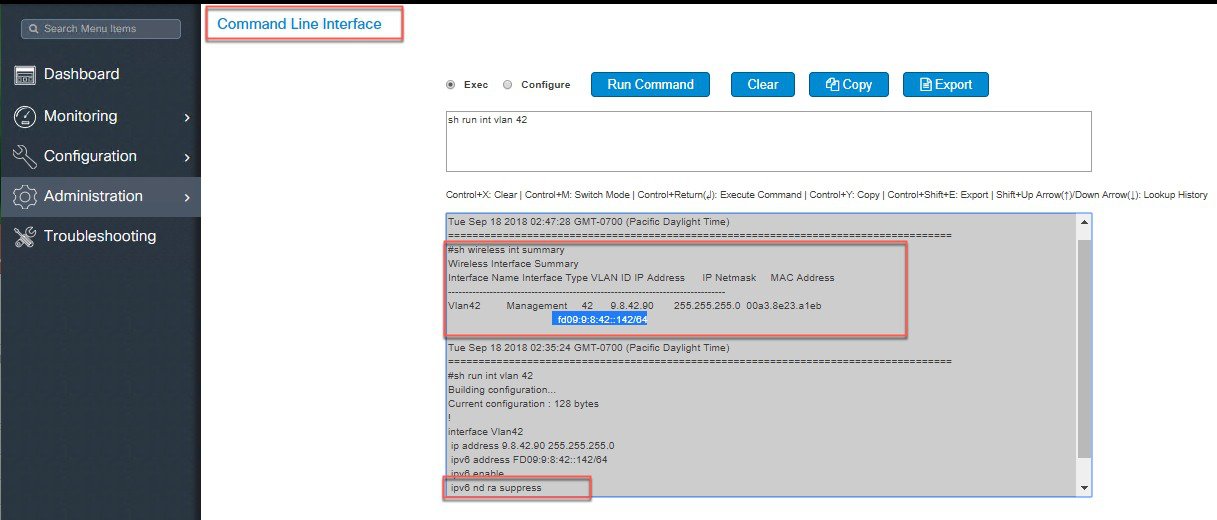
Configure using CLI or WebUI one Global Management Interface with IPv6 address: Configure the IPv6 address of the Management VLAN interface. 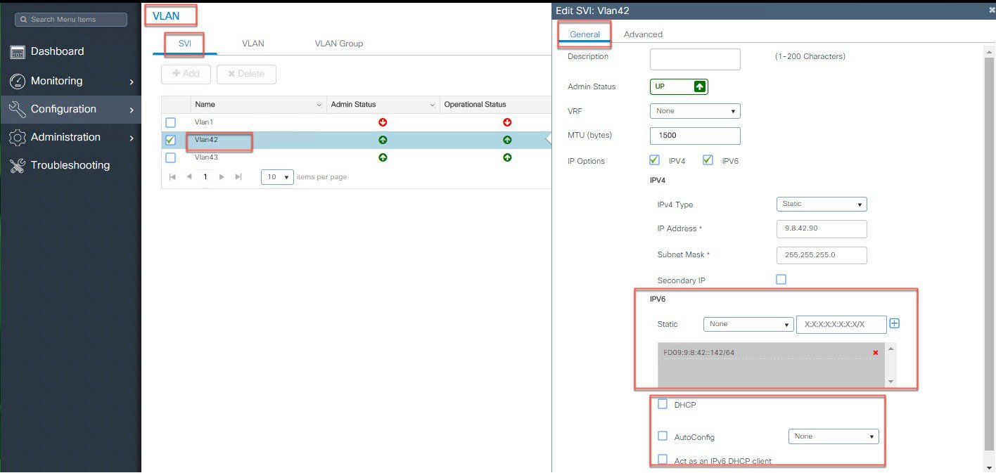 |
| Step 2 |
Configure IPv6 Static Route on the controller - This is very important step to insure all wireless client traffic has only one default route in a pure IPv6 deployments. 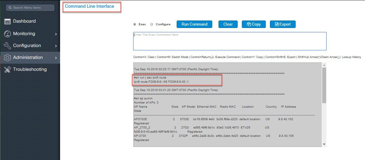 |
| Step 3 |
Configure Authentication and Authorization Servers with IPv6 address. 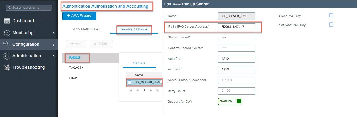 |
| Step 4 |
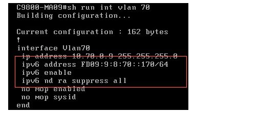
Configure RA Throttle Policy using CLI or WebUI. To throttle excessive RAs on C9800, these configurations are needed. 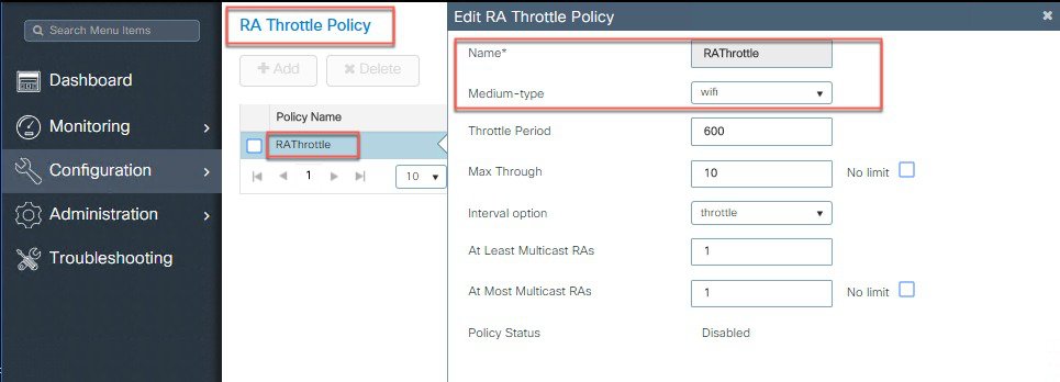 |
| Step 5 |
Configure IPv6 Multicast on the controller using CLI. To configure MoM, the following line is needed. To turn off MoM, use 0.0.0.0 as the multicast IP address. Same can be done from The WebUI. 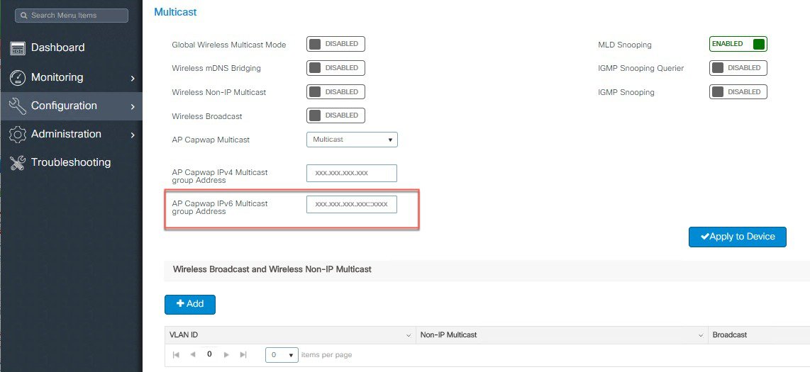 |
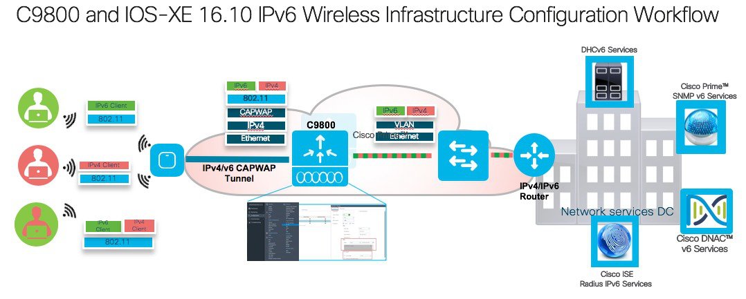
Infrastructure IPv6 Support in C9800 Release IOS-XE 16.10
This section provides a set of instructions to effectively configure native IPv6 features based on C9800 Release IOS-XE 16.10.
The following are the Infrastructure IPv6 configuration items:
-
Support Configuration of Preferred IPv4 or IPv6 Dual Stack Mode APs
-
Support of the HA Mode with Primary/Secondary/Tertiary Controllers
-
Support of IPv6 Mobility Peers and Guest Networks
-
Support of the IPv6 Multicast
-
IPv6 support of the TFTP/FTP, NTP, DNS and SNMP servers
-
IPv6 Ping and Trace Route Support
Procedure
| Step 1 |
Configure Global Preferred AP Joint Profile for IPv6.
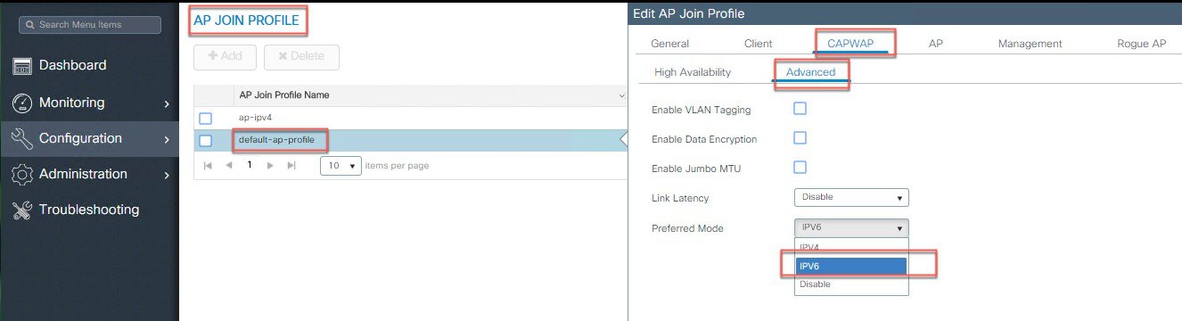 To view in what mode the AP has joined the controller, check under Monitoring > AP Statistics > Join Statistics. 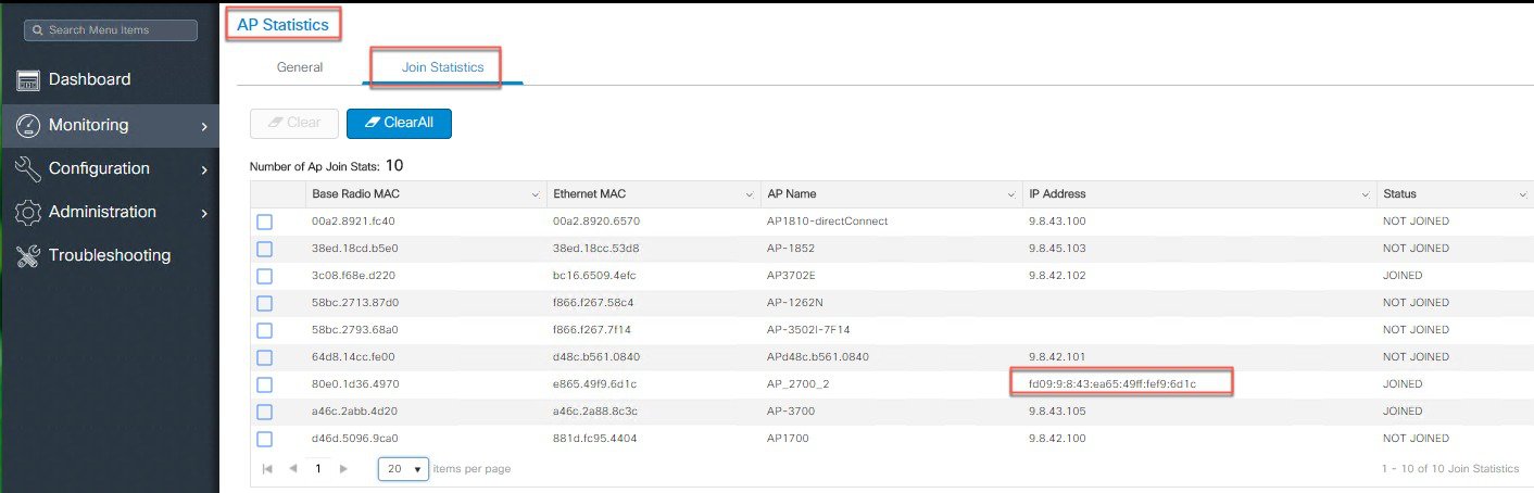 The same can be verified using the CLI commands: 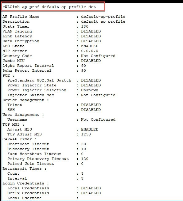 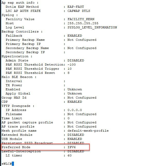 Same is shown with the execution of the CLI command. |
||
| Step 2 |
Configure CAPWAP HA Primary and Secondary Controllers IPv6 addresses.
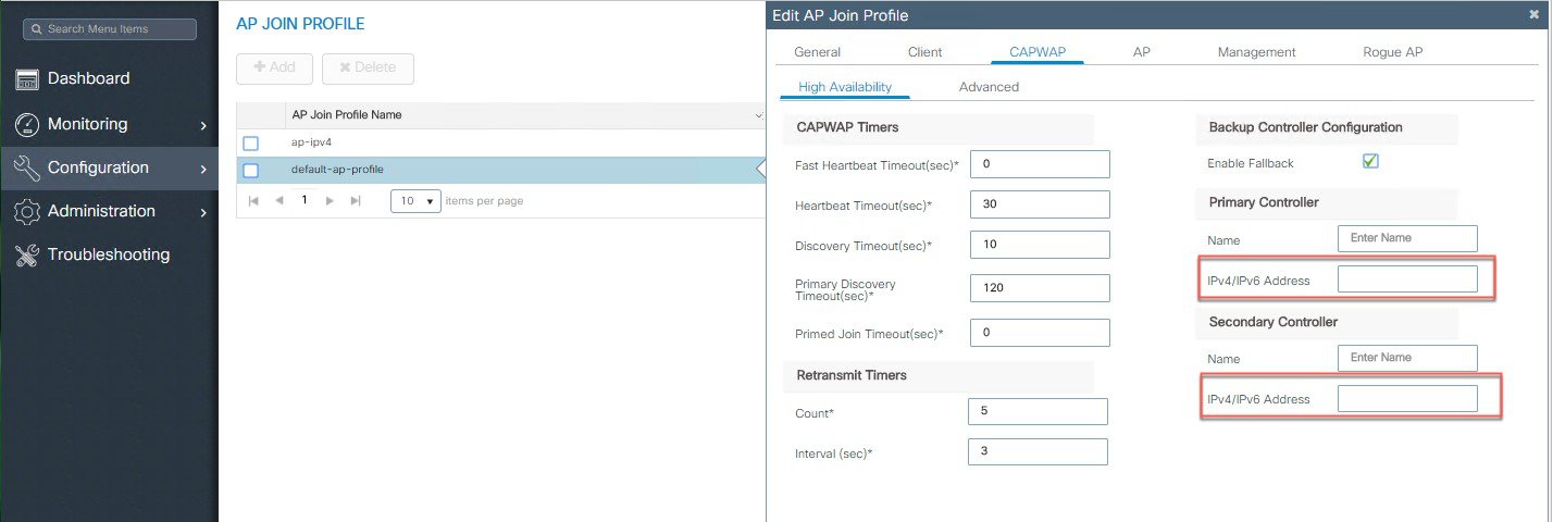 |
||
| Step 3 |
Configure Individual AP SLAAC IPv6 address.
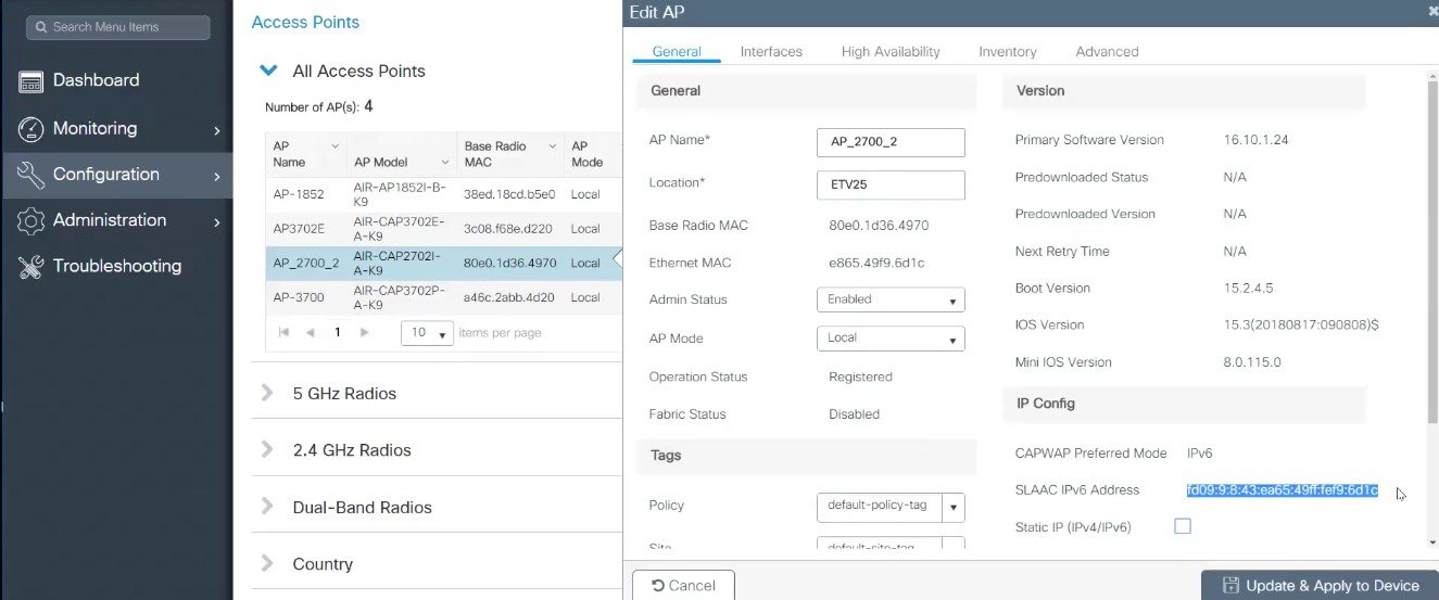 |
||
| Step 4 |
Configure Wireless Mobility Peers and Multicast IPv6 addresses.
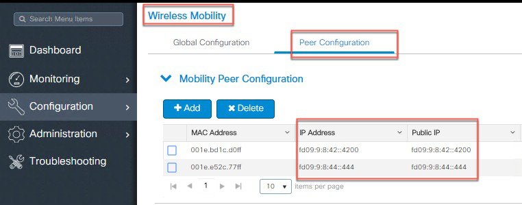  |
||
| Step 5 |
Configure AP CAPWAP IPv6 Multicast Group Address.
 |
||
| Step 6 |
Configure IPv6 Inbound and Outbound ACL on the WLAN.
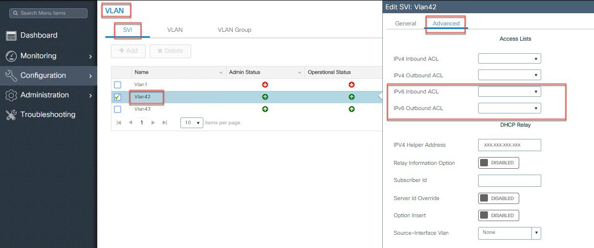 |
||
| Step 7 |
Configure IPv6 Standard ACLs.
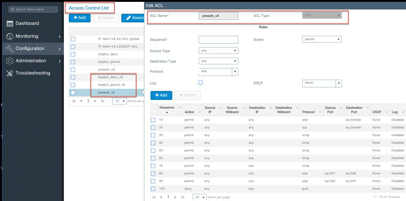 |
||
| Step 8 |
Configure Controller SNMP IPv6 address.
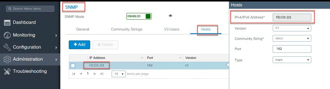 |
||
| Step 9 |
Configure Source IPv6 address for Software Upgrade server.
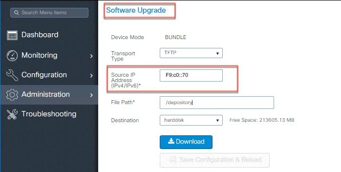 |
||
| Step 10 |
Configure IPv6 address for DNS Server.
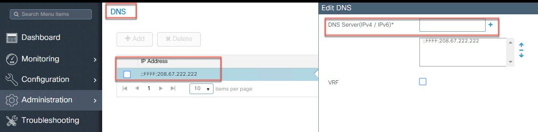 |
||
| Step 11 |
Configure IPv6 address for NTP Server.
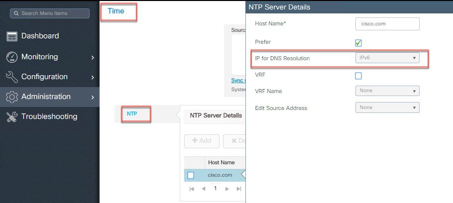 |
||
| Step 12 |
IPv6 Ping and Trace Route.
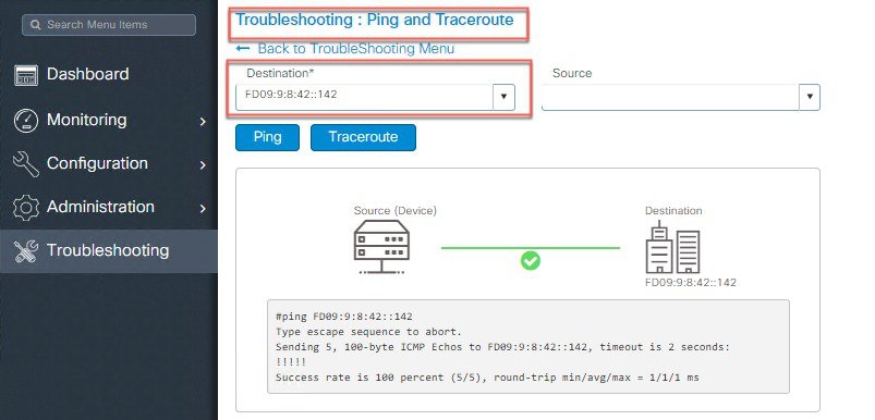 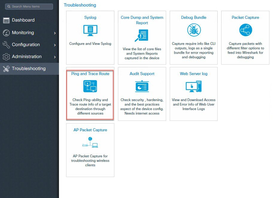 |
Enabling IPv6 on Your IOS Infrastructure Device
Enabling IPv6 on an individual infrastructure device to which wireless controller will be connected. Refer to the following Cisco documentations for configuring IPv6 on other IOS devices.
Glossary
-
AP-Access Point
-
ARP-Address Resolution Protocol
-
CAPWAP-Control And Provisioning of Wireless Access Points
-
CLI-Command Line Interface
-
CPP-Cisco Packet Processor
-
CWDB-Common Wireless DataBase
-
DAD-Duplicate Address Detection
-
DHCP-Dynamic Host Configuration Protocol
-
CWC 9800-Elastic Wireless LAN Controller
-
IOSd-IOS daemon
-
IFID–Interface Identifier
-
IP-Internet Protocol
-
IPC-Inter-Process Communication
-
MAC-Medium Access Control
-
MC2UC-Multicast to Unicast
-
MGID-Multicast Group ID
-
MOM-Multicast-Over-Multicast
-
MOU-Multicast-Over-Unicast
-
NA-Neighbor Advertisement
-
ND-Neighbor Discovery
-
NDP-Neighbor Discovery Protocol
-
NGWC-Next Generation Wiring Closet
-
NS-Neighbor Solicitation
-
ODM-Operational Data Manager
-
RA-Router Advertisement
-
RS-Router Solicitation
-
RP–Redundancy Port
-
SISF-Switch Integrated Security Module
-
SLAAC-StateLess Auto Address Configuration
-
VLAN-Virtual LAN
-
WCM-Wireless Controller Module
 Feedback