Converged Access CT 5760 AVC Deployment Guide, Cisco IOS XE Release 3.3
Available Languages
Table Of Contents
Converged Access CT 5760 AVC Deployment Guide, Cisco IOS XE Release 3.3
Application Visibility (AV) Configuration
Restrictions for AV and Control (C) in Release 3.3
Configuring AV and Control (GUI)
Flexible Netflow Collector CLI Configuration
IOS XE 3.3 AV Supported Features
Configuration of LAB Core Switch (Capture for POD 1 Setup)
Individual POD L2 Switch (Capture from POD 1 Switch)
DHCP Server Configuration for POD 1
Converged Access CT 5760 AVC Deployment Guide, Cisco IOS XE Release 3.3
Last Updated: November, 2013
Introduction
This guide is designed to help you deploy and monitor new features introduced in the IOS XE 3.3 release. All sections apply to both the 5760 and 3850 products. The document builds on previous releases with the assumption that users are familiar with the Converged Access products. Please refer to both the 5760 and 3850 deployment guides for released features that are not covered in this guide:
CT 5760 Deployment Guide
CAT 3850 Deployment Guide
http://www.cisco.com/en/US/prod/collateral/switches/ps5718/ps12686/deployment_guide_c07-727067.html
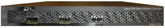
CT5760 Controller
CT5760 is an innovative UADP ASIC based wireless controller deployed as a centralized controller in the next generation unified wireless architecture. CT 5760 controllers are specifically designed to function as Unified model central wireless controllers. They also support newer Mobility functionality with Converged Access switches in the wireless architecture.
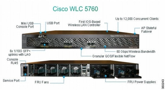
CT5760 is an extensible and high performing wireless controller, which can scale up to 1,000 access points and 12,000 clients. The controller has 6 - 10 Gbps data ports.
As a component of the Cisco Unified Wireless Network, the 5760 series works in conjunction with Cisco Aironet access points, the Cisco Prime infrastructure and the Cisco Mobility Services Engine to support business-critical wireless data, voice, and video applications.
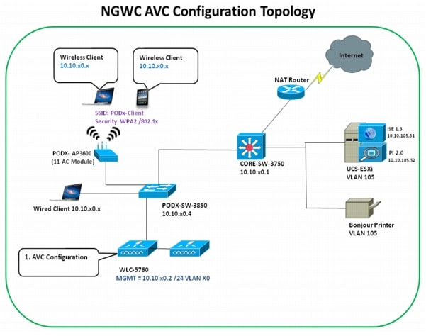
AVC Design Topology Sample
In order to derive the most out of this deployment guide and exercise the functionality outlined in this document, it is important to have a network that is configured properly with IPv4 configuration on switches and controllers. All sample design lab resources are configured as depicted in the diagram. Most lab deployments are usually configured in labs or private networks with a minimal set of controllers, Access Points, and clients.
Application Visibility (AV) Configuration
Network Based Application Recognition (NBAR2) provides application-aware control on a wireless network and enhances manageability and productivity. It also extends Cisco's Application Visibility and Control (AVC) as an end-to-end solution, which gives a complete visibility of applications in the network and allows the administrator take some action on the same.
NBAR2 is a deep-packet inspection technology available on Cisco IOS based platforms, which supports stateful L4 - L7 classification. NBAR2 is based on NBAR and has extra requirements such as having a Common Flow Table for all IOS features, which use NBAR. NBAR2 recognizes applications and passes this information to other features, such as QoS, NetFlow, and Firewall, which can take action based on this classification.
You can configure and monitor Application Visibility (AV) from both the GUI and CLI.

Note
In this release, the AV is only supported. The Control (C) part will be introduced in future releases.
Restrictions for AV and Control (C) in Release 3.3
•
•
•
•
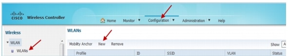
Configuring AV and Control (GUI)
Note
Note
Step 1
Map this WLAN to management interface i.e VLAN X0
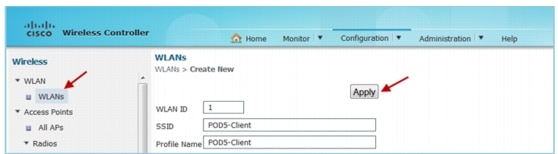
a
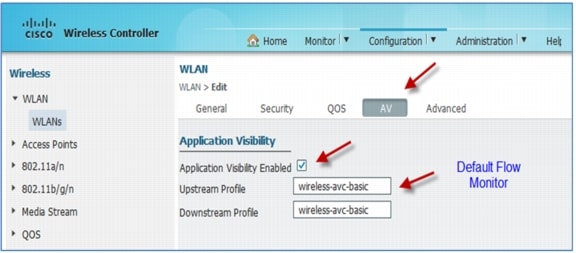
Step 2
The Application Visibility page appears.
a.
b.
c.
Step 3
Step 4
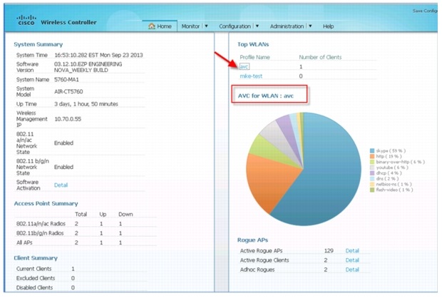
Once the AV is enabled on the specific WLAN, from the associated wireless client, start different types of traffic using applications such as Skype, Yahoo Messenger, HTTP, HTTPS/SSL, Microsoft Messenger, YouTube, Ping, Trace route, and so on. Once traffic is initiated from the wireless client, visibility of different traffic can be observed globally for all WLANs, per Client Basis and per WLAN Basis, which give a very good overview of the network bandwidth utilization and type of traffic in the network per client, per wlan and globally to an administrator.
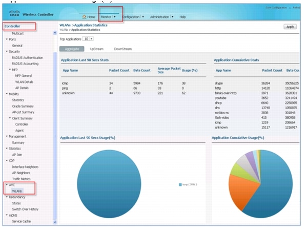
Monitoring AV (GUI)
Navigate to the Home page of the controller that displays the AV on the WLAN pie chart that contains Aggregate - Application Cumulative usage %. The top WLANs based on the WLAN IDs are displayed first.
Step 1
Step 2
The Application Statistics page appears. From the Top Applications drop-down list, select the number of top applications that you want to view and click Apply. The valid range is between 5 to 30, in multiples of 5.
a.
•
•
•
•
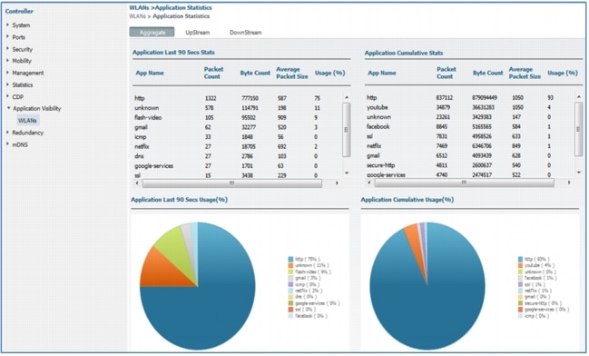
Step 3
Step 4
a.
•
•
•
•
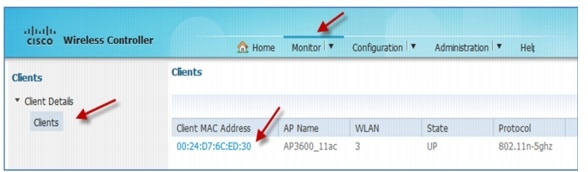
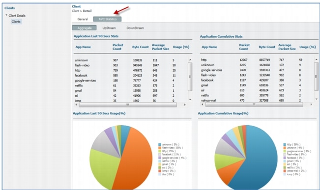
Output by Client MAC Address
Flexible Netflow Collector CLI Configuration
Cisco IOS® Flexible NetFlow is the next generation in flow technology. It optimizes the network infrastructure, which reduces operation costs and improves capacity planning and security incident detection with increased flexibility and scalability. The ability to characterize IP traffic and identify its source, traffic destination, timing, and application information is critical for network availability, performance, and troubleshooting. When IP traffic flows are monitored, this increases the accuracy of capacity planning and ensures that resource allocation supports organizational goals. Flexible NetFlow helps you determine how to optimize resource usage, plan network capacity, and identify the optimal application layer for QoS. It plays a vital role in network security by the detection of Denial of Service (DoS) attacks and network-propagated worms.
Here are the commands to configure Flexible Netflow:
!
flow record IPv4flow
match ipv4 protocol
match ipv4 source address
match ipv4 destination address
match flow direction
collect counter bytes long
collect counter packets long
collect timestamp absolute first
collect timestamp absolute last
!
!
flow exporter IPv4export-1
destination 10.1.1.6 (IP address of your Netflow Collector. It should be v9
netflow.
transport udp 2055
!
!
flow monitor IPv4flow (you can view the flows on the switch using CLI if netflow
Collector not available)
description Monitor all IPv4 traffic
exporter IPv4export-1
cache timeout active 30
record IPv4flow
!
Here are the Show Commands:
show flow monitor name monitor-name cache
show flow record
show flow-sampler
show flow monitorFor additional information on Netflow Configuration, please refer to Cisco Flexible NetFlow Configuration Guide, Cisco IOS XE Release 3SE (Catalyst 3850 Switches).
IOS XE 3.3 AV Supported Features
•
•
•
•
•
•
•
•
•
NBAR/AV Summary
•
•
•
•
•
NBAR Feature Limitation
•
•
•
•
Appendix
Network Components
5760 Configuration Example
5760-1#
!
version 15.0
no service pad
service timestamps debug datetime msec
service timestamps log datetime msec
no service password-encryption
service compress-config
!
hostname 5760-1
!
boot-start-marker
boot-end-marker
vrf definition Mgmt-vrf
!
address-family ipv4
exit-address-family
!
address-family ipv6
exit-address-family
!
logging console emergencies
enable password Cisco123
!
username admin privilege 15 password 0 Cisco123
user-name miadler
creation-time 1374089252
privilege 15
password 0 Cisco123
type mgmt-user
aaa new-model
!
aaa local authentication default authorization default
aaa session-id common
clock timezone EST -5 0
switch 1 provision air-ct5760-6
switch 2 provision air-ct5760-6
!
flow record fr-avc
match ipv4 protocol
match ipv4 source address
match ipv4 destination address
match transport source-port
match transport destination-port
match flow direction
match application name
match wireless ssid
collect counter bytes long
collect counter packets long
collect wireless ap mac address
collect wireless client mac address
!
!
flow monitor fm-avc
cache timeout inactive 200
record fr-avc
!
flow monitor wireless-avc-basic
record wireless avc basic
!
ip dhcp-server 10.70.0.1
ip device tracking
ip dhcp snooping vlan 70
ip dhcp snooping
!
qos wireless-default-untrust
!
crypto pki trustpoint TP-self-signed-545652971
enrollment selfsigned
subject-name cn=IOS-Self-Signed-Certificate-545652971
revocation-check none
rsakeypair TP-self-signed-545652971
!
!
crypto pki certificate chain TP-self-signed-545652971
!
diagnostic bootup level minimal
identity policy webauth-global-inactive
inactivity-timer 3600
spanning-tree mode pvst
spanning-tree extend system-id
!
redundancy
mode sso
service-list mdns-sd gui-deny-all deny 20
!
service-list mdns-sd gui-permit-all permit 10
!
service-routing mdns-sd
service-policy gui-permit-all IN
service-policy gui-deny-all OUT
!
class-map match-any non-client-nrt-class
match non-client-nrt
interface Port-channel1
switchport trunk allowed vlan 70
switchport mode trunk
ip dhcp snooping trust
!
interface GigabitEthernet0/0
vrf forwarding Mgmt-vrf
ip address 10.91.104.101 255.255.255.0
ip helper-address 10.70.0.1
negotiation auto
!
interface TenGigabitEthernet1/0/1
switchport trunk allowed vlan 70
switchport mode trunk
channel-group 1 mode active
ip dhcp snooping trust
!
interface TenGigabitEthernet1/0/2
switchport trunk allowed vlan 70
!
interface TenGigabitEthernet1/0/3
!
interface TenGigabitEthernet1/0/4
!
interface TenGigabitEthernet1/0/5
!
interface TenGigabitEthernet1/0/6
!
interface TenGigabitEthernet2/0/1
switchport trunk allowed vlan 70
switchport mode trunk
channel-group 1 mode active
ip dhcp snooping trust
!
interface TenGigabitEthernet2/0/2
!
interface TenGigabitEthernet2/0/3
!
interface TenGigabitEthernet2/0/4
!
interface TenGigabitEthernet2/0/5
!
interface TenGigabitEthernet2/0/6
!
interface Vlan1
no ip address
shutdown
!
interface Vlan70
ip address 10.70.0.55 255.255.255.0
ip helper-address 10.70.0.1
!
interface Vlan72
ip address 10.72.0.10 255.255.255.0
!
ip default-gateway 10.70.0.1
ip http server
ip http authentication local
ip http secure-server
!
!
!
snmp-server location TME Lab MA
snmp-server contact Mike
!
!
!
line con 0
exec-timeout 0 0
stopbits 1
line aux 0
stopbits 1
line vty 0 4
password Cisco123
line vty 5 15
!
wsma agent exec
profile httplistener
profile httpslistener
wsma agent config
profile httplistener
profile httpslistener
wsma agent filesys
profile httplistener
profile httpslistener
wsma agent notify
profile httplistener
profile httpslistener
!
wsma profile listener httplistener
transport http
!
wsma profile listener httpslistener
transport https
mac address-table aging-time 15 vlan 70
wireless mobility controller peer-group MA-SPG1
wireless mobility controller peer-group MA-SPG1 member ip 10.70.0.65 public-ip 10.70.0.65
wireless mobility controller peer-group MA-SPG1 member ip 10.70.0.55 public-ip 10.70.0.55
wireless mobility group name miadler
wireless management interface Vlan70
wireless rf-network miadler
wlan avc 1 avc
client vlan VLAN0070
ip flow monitor wireless-avc-basic input
ip flow monitor wireless-avc-basic output
no security wpa
no security wpa akm dot1x
no security wpa wpa2
no security wpa wpa2 ciphers aes
session-timeout 1800
no shutdown
wlan mike-test 2 mike-test
client vlan VLAN0070
ip dhcp server 10.70.0.1
ip flow monitor wireless-avc-basic input
ip flow monitor wireless-avc-basic output
no security wpa
no security wpa akm dot1x
no security wpa wpa2
no security wpa wpa2 ciphers aes
session-timeout 1800
no shutdown
ap led
no ap capwap fallback
ap group default-group
endConfiguration of LAB Core Switch (Capture for POD 1 Setup)
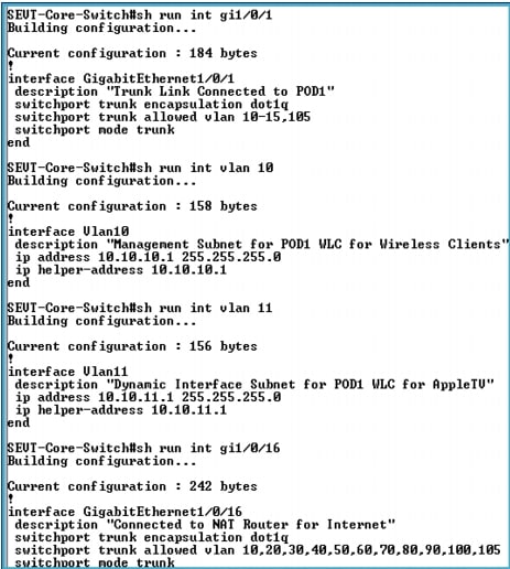
Note
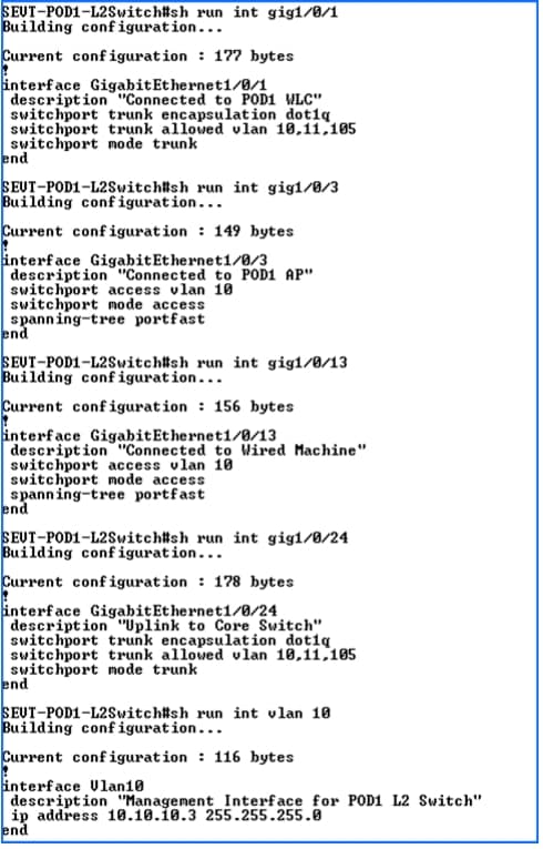
Individual POD L2 Switch (Capture from POD 1 Switch)
DHCP Server Configuration for POD 1
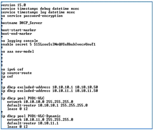
Note
 Feedback
Contact Cisco
- Open a Support Case

- (Requires a Cisco Service Contract)