Test Deployment Models and Sites
Available Languages
Table Of Contents
Test Deployment Models and Sites
Deployment Models and Test Beds
Test Bed Software Implementation
Cisco Unified Contact Center Enterprise and Cisco Unified Intelligent Contact Management Enterprise
Cisco Unified Customer Voice Portal
Cisco Unified Contact Center Gateway Enterprise Feature
Cisco Unified Contact Center Gateway and Cisco Unified System Contact Center Gateway
Cisco Unified System Contact Center
Deployment Options for Call Flows in Test Bed 1
Test Bed 1: Unified IP IVR Test Sites
Site Relationships and Call Routing
Topology of Cisco Unified IP IVR Sites
Snapshot of Unified IP IVR Sites Components
Parent and Child Topology in Test Bed 1
Site Relationships and Call Routing
Unified IP IVR Site Definitions
Test Bed 2: Unified CVP Test Sites
Site Relationships and Call Routing
Snapshot of Unified CVP Sites Components
Site6: Mid-Atlantic Retail Center
Site7: North-Central Retail Center
Site8: South-Central Retail Center
Test Deployment Models and Sites
This topic describes the deployment models and test beds that were designed and tested as part of Cisco Unified Communications System Release 5.0 for Contact Center.
This topic contains the following sections:
•
Deployment Models and Test Beds
•
•
•
In "Test Case Studies", we discussed and defined business requirements that would require a contact center system for two fictitious businesses with call centers:
•
•
For guidelines, recommendations, and best practices to help you design and deploy enterprise networking solutions based on your specific business needs and requirements, see the Cisco Solution Reference Network Design (SRND) guides, which are available at: http://www.cisco.com/go/srnd
Deployment Models and Test Beds
The following three deployment models were implemented to test the contact center solution that was developed from the business case studies:
Typically, a model deploying centralized call processing servers or voice gateways is adequate for an enterprise with small remote sites or offices in a metropolitan area. However, a distributed deployment model is more efficient as sites become larger or more geographically disperse.
The sites were configured and deployed based on the customer requirements and testing was done to validate the interoperability of the contact center components.
Two test beds were then set up based on an multisite distributed deployment model encompassing one or more multi site centralized deployment models, including a single-site deployment model.
For ease of use, we will use Test Bed 1 and Test Bed 2 to refer to the two test beds described below and site numbers to refer to sites in each test bed.
The two test beds are:
•
Additionally, in Test Bed 1, Cisco Unified Contact Center Gateway Enterprise (Unified CCGE) feature and the parent and child model are implemented. See Cisco Unified Contact Center Gateway Enterprise Feature for more information.
•
Single-site
In the single-site deployment model, all the voice gateways, agents, desktops, Cisco Unified IP Phones (Unified IP Phones), and call processing servers such as Cisco Unified CallManager (Unified CallManager), Cisco Unified Intelligent Contact Management (Unified ICM), and CRS (Unified IP IVR) and/or Unified CVP are located at the same site and have no WAN connectivity between any Unified Contact Center Enterprise (Unified CCE) software modules.
Multisite Centralized
In the multisite WAN model with centralized call processing, the Unified CallManager cluster resides at a central (or hub) campus and communications with remote offices take place over the IP WAN. The central site or data center provides the call processing services and acts as the hub for the remote sites.
This deployment model also contains distributed voice gateways for locally dialed calls.
In both test beds, a distributed data center is implemented at the data center locations, for geographic redundancy of the Unified CCE components such as Central Controller (Call Router and Logger known as Rogger), Peripheral Gateways, Unified CallManager, CTI OS and CAD Servers, and is split across the WAN. This type of deployment is referred to as Clustering over the WAN (CoW) for Unified CCE and provides full agent redundancy in the case of a data center outage.
Multisite Distributed
In the multisite WAN model with distributed call processing, typically, some sites have their own Unified CallManager cluster and are interconnected with inter-cluster trunks (ICT Trunking). Similar to the multisite centralized deployment model, sites in the multisite WAN distributed model are deployed with distributed voice gateways. Communication between sites takes place over the IP WAN.
Test Bed Software Implementation
In this section, we discuss how customer contact software, network management, security, CRS (Unified IP IVR), Unified CVP, the Unified CCGE feature, and the parent and child model are implemented in the test beds.
Cisco Unified Contact Center Enterprise and Cisco Unified Intelligent Contact Management Enterprise
Unified CCE and Unified ICM, integral components of the Cisco Unified Communications system, provide intelligent routing and call treatment with transparent blending of multiple communication channels, while easing the transition from a traditional automatic call distributor (ACD) to an IP-based ACD.
Unified CCE/Unified ICM are part of a strategic platform that helps customers move into the next phase of customer contact, beyond today's contact center to a Customer Interaction Network. The Customer Interaction Network is a distributed, IP-based customer service infrastructure that comprises a continuously evolving suite of innovative, multichannel services and customer-relationship-management (CRM) applications.
Unified CCE/Unified ICM software is deployed at the test sites in the contact center environment. With Unified CCE/Unified ICM, the call center manager can configure agents to handle inbound and outbound voice, Web collaboration, text chat, and e-mail requests. The agents can switch between these media on a task-by-task basis. Customers can choose the medium that is most comfortable and convenient for them. Unified CCE/Unified ICM can be used in a single-site environment or integrated into a multisite call center.
Cisco Unified Customer Voice Portal
The Cisco Unified Customer Service Portal (Unified CVP) provides interactive voice response and queueing capabilities in a contact center environment and supports automated speech recognition (ASR) and text-to-speech (TTS) capabilities. Unified CVP, which is implemented at this test environment in the comprehensive mode, includes support for agent queueing, multisite call switching, and speech-enabled and touch-tone applications. Unified CVP consists of the Voice Browser which plays media files to the caller and collects information in return, and the Application Server which interprets messages from Unified ICM and generates VXML documents that it uses to communicate with the Voice Browser.
Customer Response Solutions
CRS implementation at the test sites includes the Cisco Unified IP Interactive Voice Response (Unified IP IVR) product. Unified IP IVR is a multimedia (voice, data, and web) IP-enabled interactive voice response solution that automates call handling by autonomously interacting with contacts.
Using Unified IP IVR, one can create applications that answer calls, provide menu choices for callers, obtain caller data such as passwords or account identification, and transfer calls to caller-selected extensions.
Unified IP IVR is a part of the Unified CCE solution, which is capable of distributing calls to multiple sites and performing pre- and post-routing functions. Unified CCE uses Unified ICM software to direct calls to other systems, such as interactive VRUs and ACD systems.
For purposes of this manual, we will refer to this version of the CRS implementation interchangeably as CRS (when referring to the system) or as Unified IP IVR (when referring to the product).
Network Management
Network Management is implemented at all the test sites by using the following reporting tools:
•
•
•
RTMT continuously monitors a set of management objects that are preconfigured and generates various alerts, in the form of emails, for these objects when values go over/below user-configured thresholds. RTMT then generates daily reports for these objects.
•
Security
CiscoWorks Management Center for Cisco Security Agents is implemented at the various sites as follows:
•
•

Note
Cisco Unified Contact Center Gateway Enterprise Feature
The following is a brief description of the Cisco Unified Contact Center Gateway (Unified CCGE) feature that is part of the Cisco Unified Communications System Release 5.0 for Contact Center. The following features are relevant to the new functionality:
•
•
•
•
Cisco Unified Contact Center Gateway and Cisco Unified System Contact Center Gateway
In an Unified CCGE deployment, Unified CCE appears as a traditional ACD connected to the Cisco Unified Intelligent Contact Management (Unified ICM) system. Unified ICM uses Unified CCGEs to communicate to the CTI server on the Unified SCCG in Unified CCE.
Unified CCGE provides all standard Peripheral Interface Manager (PIM) data and functionality including translation routing, pre- and post-routing, and an auto configuration feature that eliminates repeating configuration tasks between the Unified CCE and Unified ICM systems.
Cisco Unified System Contact Center
Cisco Unified System Contact Center (Unified SCC) is installed at the single-site and participates in the parent and child model. Unified SCC is installed on a single server as an all-in-one implementation (known as the Progger) combining major software processes such as the Peripheral Gateway (PG), Router, Logger, Unified CallManager PIM, Unified IP IVR PIMs, CTI Server, Customer Telephony Integration Object Server (CTI OS) and Cisco Agent Desktop (CAD) servers.
The Unified SCC deployment has a streamlined installation and a browser-based interface associated with it. The new Unified CCE Secure Web Administration, available exclusively with this model:
•
•
Parent and Child Model
The Unified CCGE feature and the parent and child model are implemented for testing additional contact center functionality. In the parent and child model, the child system is configured to function completely on its own and does not need the connection to the parent to route calls to agents. This independence provides complete local survivability for mission-critical call centers if the network between the child and parent goes down or if there is a problem with the parent or the gateway connection.
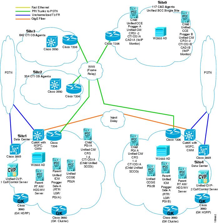
The parent and child model on Test Bed 1 is deployed as a single parent system with multiple child systems. Unified CCGEs are installed at the parent sites and Cisco Unified System Contact Center Gateways (Unified SCCGs) are installed at both the parent and child sites. Figure 2-2 shows the sites and components participating in the parent and child deployment in Test Bed 1.
Parent and Child Systems Relationships
The systems in an Unified CCGE deployment play different roles. The following terms describe the relationship between these roles:
•
•
The parent system does the following:
•
•
•
–
–
The child system does the following:
•
•
•
The advantage with the parent and child deployment is that call center operations can continue, even if the WAN connection between the data centers and remote sites is not operational.
For detailed information on the parent and child deployment, see the Cisco IPCC Gateway Deployment Guide ICM/IPCC Enterprise Edition Release 7.0(0) at:
http://www.cisco.com/application/pdf/en/us/guest/products/ps1001/c1097/ccmigration_09186a0080626383.pdfDeployment Options for Call Flows in Test Bed 1
Table 2-1 provides a brief overview of the deployment options available for the Parent/Child call flow and the Unified CallManager Post-Routed call flow in Test Bed 1.
Table 2-1 Deployment Options in Test Bed 1
Single-site
Multisite Centralized
Multisite Distributed
CoWSingle-site
Multisite Centralized
Multisite Distributed
CoWSingle-site
Multisite Centralized
Multisite Distributed
CoWPROGGER
-or-
ROGGERPROGGER
-or-
ROGGERPROGGER
-or-
ROGGERco-located vs. geographically separate
co-located vs. geographically separate
co-located vs. geographically separate
co-located vs. geographically separate
Unified CCGE located at parent1 or child site, but not co-resident with Unified SCCG on the same server
Unified SCCG at child sites
Unified SCCG deployment at independent single-site
Generic PG vs. Unified SCCG
Unified CCGE & VRU PG
Unified SCCGs
Centralized vs. distributed
Centralized
Centralized vs. distributed
not applicable
not supported
Maximum five (5)
CAD vs. CTI OS
No agents
CAD vs. CTI OS
Cisco Unified Outbound Dialer supported with Unified SCCG (requires a separate MR PG)
Multi-channelNo outbound agents
Cisco Unified Outbound Dialer supported with Unified SCCG (requires a separate MR PG)
Multi-channelTraditional installation (Unified ICM SetUp and Admin Workstation)
New installation with Unified CCGE
-or-
Install Unified CCGE after upgrading Unified ICMNew installation based on Unified SCCG
-or-
Install Unified SCCG after upgrading Unified CCETraditional upgrade based on single stage or multi-staged upgrade approaches
No upgrade FROM non-parent
No upgrade FROM non-Unified SCCG
Unified IP IVR
-or-
Unified CVPUnified CVP only
Unified IP IVR only
1 We recommend that Unified CCGE is co-located at the same site as Unified SCCG.
Test Bed 1: Unified IP IVR Test Sites
The following eight sites make up the single-site, multisite centralized and multisite distributed deployment models for testing the Unified CallManager (and Unified CVP for the parent and child model) Post-Routed call flow:
•
•
•
•
•
•
•
•
See Topology of Cisco Unified IP IVR Sites for a complete map of the eight sites, their individual topologies, and the relationship between the sites. See Unified IP IVR Site Definitions for more information on the individual sites in Test Bed 1.
Site Relationships and Call Routing
Listed below are the relationships of the eight sites and the call routing deployed in Test Bed 1.
Multisite Centralized Site Relationships
•
•
•
•
•
•
•
Multisite Distributed Site Relationships
•
•
Call Routing
•
•
•
•
"Tested Call Flows" discusses these call flows in greater detail.
Topology of Cisco Unified IP IVR Sites
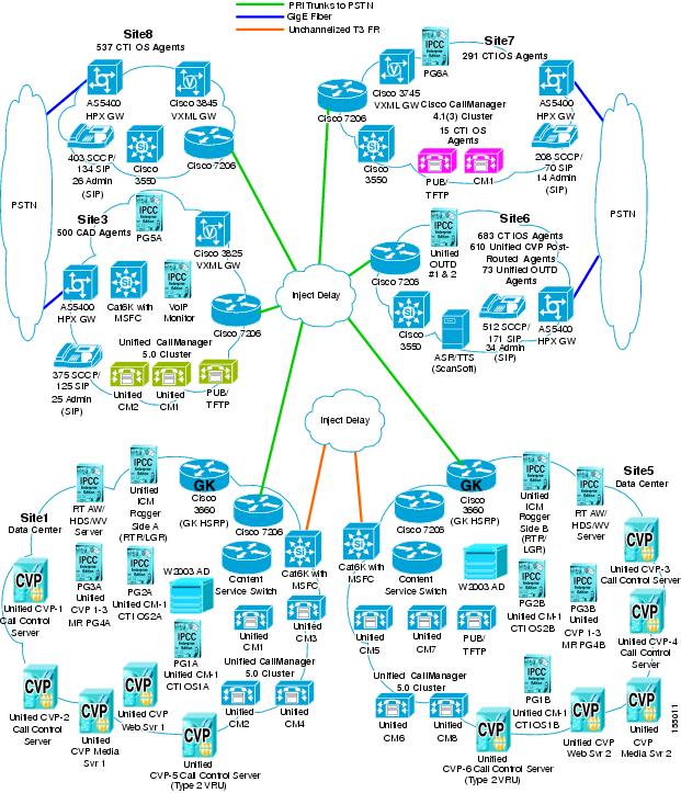
The topology and relationships of the eight sites, where Unified IP IVR is deployed, is shown in Figure 2-1:
Figure 2-1 Unified IP IVR Sites in Test Bed 1
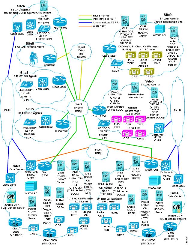
Snapshot of Unified IP IVR Sites Components
Table 2-2 provides a comprehensive view of the different components deployed at the various Unified IP IVR sites. For specific component names and quantities, see the individual site descriptions in this section.
Note
Parent and Child Topology in Test Bed 1
The topology and relationships of the five sites in Test Bed 1 configured in the parent and child model and participating components are shown in Figure 2-2.
Site Relationships and Call Routing
Listed below are the relationships of the parent and child sites and the Parent/Child call routing deployed in Test Bed 1.
Parent Sites:
•
•
–
–
–
Child Sites:
•
•
•
•
–
–
–
Parent and Child Site Relationships
•
•
•
Parent/Child Call Routing
Calls in the parent and child deployment are routed in one of the following ways:
•
•
•
"Tested Call Flows" discusses the Parent/Child call flow in greater detail.
Figure 2-2 Parent and Child Sites in Test Bed 1
Unified IP IVR Site Definitions
The following section describes the sites that were created for the various deployment models in Test Bed 1 for testing Unified CallManager Post-Routed call flows. Each topic defines the design characteristics of an individual site and includes logical and physical topology maps and a site equipment table.
Note
Site1: Data Center Site
Site Profile
Site1 is the hub and the data center in a multisite distributed WAN configuration with Site4 as its backup hub. This site acts as the hub for Site2, Site3, and Site8 remote sites. This site participates as the parent, along with Site4, in the parent and child deployment.
The test site is deployed as follows:
•
–
–
•
–
–
–
•
–
–
–
–
•
–
–
The Unified CCGE supports two Peripheral Interface Manager (PIMs) to provide connectivity to the peripherals or child systems at the remote sites.
The Unified SCCGs are used to communicate with the local Unified CallManager cluster, the CRS system, CTI OS servers, and the Unified OUTD in Site6.
–
–
–
–
–
–
•
–
•
–
•
–
–
–
–
•
–
–
–
Figure 2-3 shows the logical topology of Site1.
Figure 2-3 Site1 Logical Topology
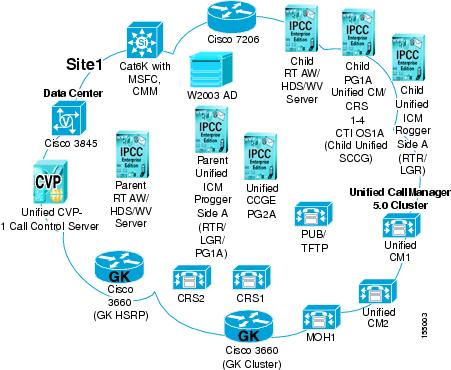
Table 2-3 lists the equipment and hardware platforms used in Site1. Use the reference information in the table to access corresponding software versions and model numbers.
Table 2-3 Site1 Equipment List
Access Switch
Catalyst 6509
1
Alarm Tracker
MCS-7845H-2.4-EVV1
1
Unified CallManager
MCS-7845H-3.0-IPC1
3
CMM (SIP) Gateway
Catalyst 6500 (MSFC)
1
CRS (Unified IP IVR)
MCS-7845H-2.4-EVV1
2
CiscoWorks Management Center
MCS-7845H-2.4-EVV1
1
CiscoWorks Management Center for Cisco Security Agent and Cisco Security Agent
Unified CVP Servers
MCS-7845H-2.4-EVV1
2
Domain Controller
MCS-7845H-3000
1
Gatekeeper (Cluster and HSRP)
Cisco 3660
3
HW Conference/MTP
Catalyst 6509 CMM (ACT)
1
Unified CCGE
MCS-7845H-2.4-EVV1
1
Unified SCCG
MCS-7845H-H1-CC1
1
Unified IP Phones
Unified IP Phones (SCCP) 7940/7960/7970
2
Music on Hold (MOH)
MCS-7845H-2.4-EVV1
1
PSTN/VXML Gateway
Cisco 3745
1
Progger (Parent)
MCS-7845H-2.4-EVV1
1
Rogger (Child)
MCS-7845H-H1-CC1
1
RTAW /HDS / WebView (Parent)
MCS-7845H-2.4-EVV1
1
RTAW /HDS / WebView (Child)
MCS-7845H-H1-CC1
1
WAN Router
Cisco 7206VXR
1
Windows 2003 AD
MCS-7845-1400
1
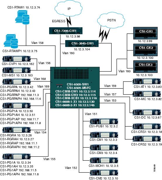
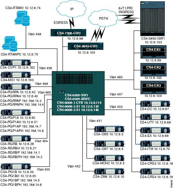
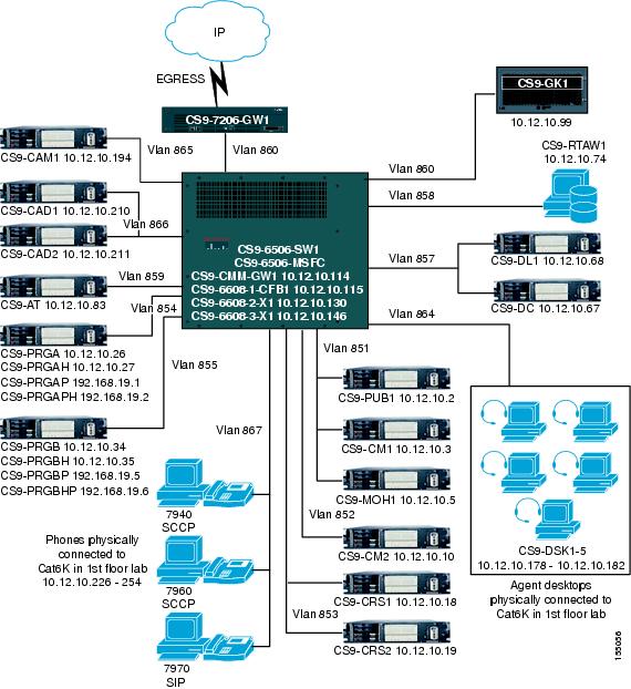
Figure 2-4 shows the physical topology of Site1 displaying the equipment listed in Table 2-2.
Figure 2-4 Site1 Physical Topology
Site2: Remote Site
Site Profile
Site2 is a small remote office of Site1 in the multisite centralized configuration. It participates in the multisite distributed WAN configuration.
The test site is deployed as follows:
•
–
–
–
–
•
–
–
•
–
–
•
–
–
•
–
–
Figure 2-5 shows the logical topology of Site2.
Figure 2-5 Site2 Logical Topology
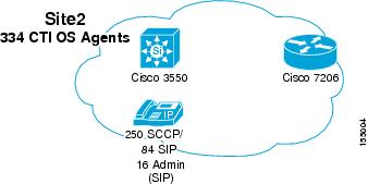
Table 2-4 lists the equipment and hardware platforms used in Site2. Use the reference information in the table to access corresponding software versions and model numbers.
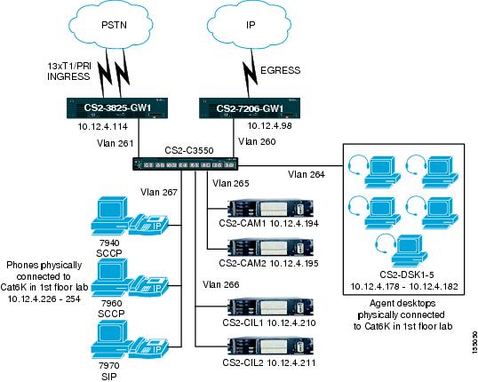
Figure 2-6 shows the physical topology of Site2 displaying the equipment listed in Table 2-3.
Figure 2-6 Site2 Physical Topology
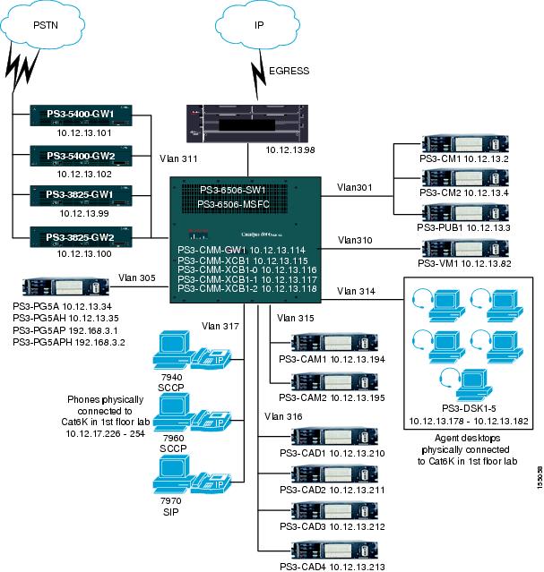
Site3: Remote Site
Site Profile
Site3 is a medium remote site of Site1 in the multisite distributed configuration. It participates in the multisite distributed WAN configuration.
The test site is deployed as follows:
•
–
–
–
•
–
–
•
–
–
•
–
–
•
–
–
Figure 2-7 shows the logical topology of Site3.
Figure 2-7 Site3 Logical Topology
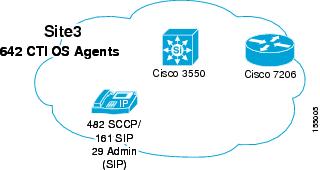
Table 2-5 shows the equipment and hardware platforms used in Site3. Use the reference information in the table to access corresponding software versions and model numbers.
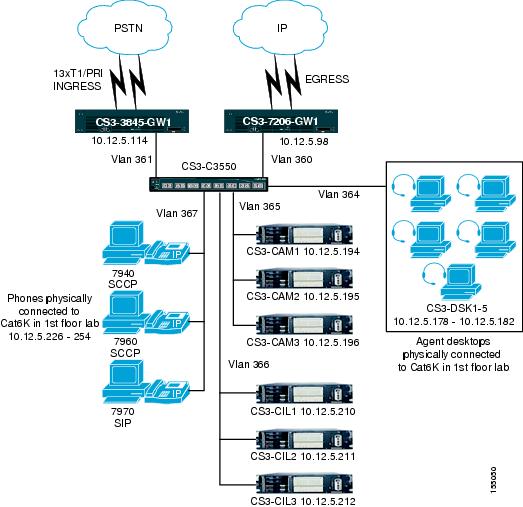
Figure 2-8 shows the physical topology of Site3 displaying the equipment listed in Table 2-4.
Figure 2-8 Site3 Physical Topology
Site4: Data Center Site
Site Profile
Site4 is a redundant hub and the backup data center for Site1 with which it participates in a multisite centralized configuration for Site2, Site3, and Site8. This site participates as the backup parent, for Site1, in the parent and child deployment. It also participates in the multisite distributed WAN configuration.
The test site is deployed as follows:
•
–
•
–
–
–
–
•
–
–
–
–
•
–
–
The Unified CCGE supports two Peripheral Interface Manager (PIMs) to provide connectivity to the peripherals or child systems at the remote sites.
The Unified SCCGs are used to communicate with the local Unified CallManager cluster, the CRS system, CTI OS servers, and the Unified OUTD in Site6.
–
–
–
–
•
–
•
–
•
–
–
–
–
•
–
–
Figure 2-9 is a logical topology of Site4.
Figure 2-9 Site4 Logical Topology
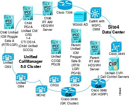
Table 2-6 lists the equipment and hardware platforms used in Site4. Use the reference information in the table to access corresponding software versions and model numbers.
Figure 2-10 shows the physical topology of Site4 displaying the equipment listed in Table 2-5.
Figure 2-10 Site4 Physical Topology
Site5: Branch Office Site
Site Profile
Site5 is a medium remote branch office in a multisite centralized configuration for Site6. It also participates in the multisite distributed WAN configuration.
The test site is deployed as follows:
•
–
–
•
–
–
•
–
•
–
–
–
–
–
•
–
–
•
–
–
Figure 2-11 shows the logical topology of Site5.
Figure 2-11 Site5 Logical Topology
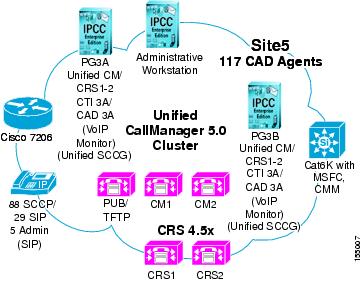
Table 2-7 lists the equipment and hardware platforms used in Site5. Use the reference information in the table to access corresponding software versions and model numbers.
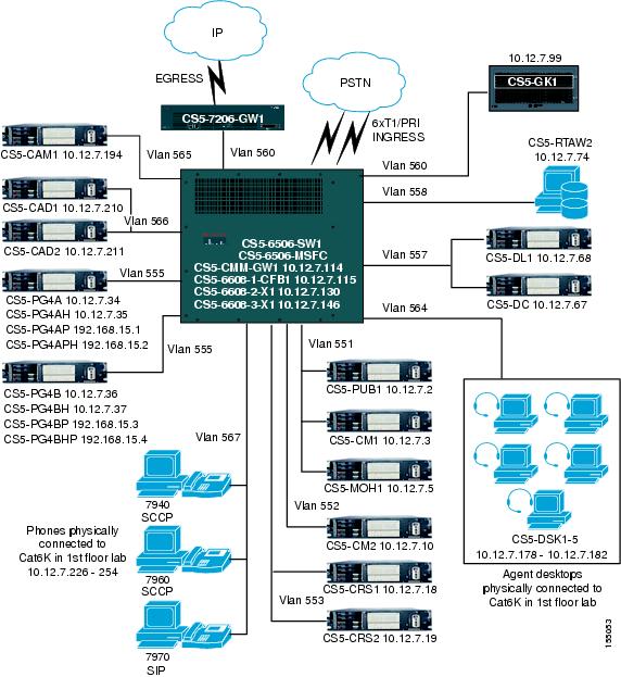
Figure 2-12 shows the physical topology of Site5 displaying the equipment listed in Table 2-6.
Figure 2-12 Site5 Physical Topology
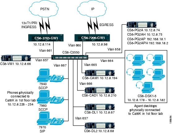
Site6: Remote Site
Site Profile
Site6 is a small remote office of Site5 which participates in the multisite centralized configuration. It also participates in the multisite distributed WAN configuration.
The test site is deployed as follows:
•
–
–
–
–
•
–
–
•
–
–
•
–
–
•
–
–
Figure 2-13 shows the logical topology of Site6.
Figure 2-13 Site6 Logical Topology

Table 2-8 lists the equipment and hardware platforms used in Site6. Use the reference information in the table to access corresponding software versions and model numbers.
Figure 2-14 shows the physical topology of Site6 displaying the equipment listed in Table 2-7.
Figure 2-14 Site6 Physical Topology
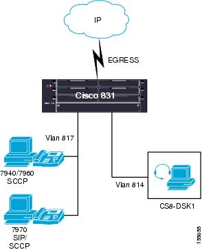
Site8: Remote Agent Site
Site Profile
Site8 is the site of the remote agent who uses the Unified CCE Home Agent with Broadband solution in the remote agent model. Site8 is associated with Site2 and participates in the multisite centralized configuration with Site1/Site4 and in the multisite distributed WAN configuration.
The test site is deployed as follows:
•
–
•
–
•
–
Figure 2-15 shows the logical topology of Site8.
Figure 2-15 Site8 Logical Topology
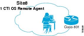
Table 2-9 lists the equipment and hardware platforms used in Site8. Use the reference information in the table to access corresponding software versions and model numbers.
Figure 2-16 shows the physical topology of Site8 displaying the equipment listed in Table 2-8.
Figure 2-16 Site8 Physical Topology
Site9: Branch Office Site
Site Profile
Site9 is a branch office, single-site deployment in the multisite centralized configuration. It also participates in the multisite distributed WAN configuration. This is also the site where Unified SCC is implemented.
The test site is deployed as follows:
•
–
–
–
•
–
•
–
–
•
–
–
–
–
–
•
–
•
–
•
–
–
Figure 2-17 shows the logical topology of Site9.
Figure 2-17 Site9 Logical Topology
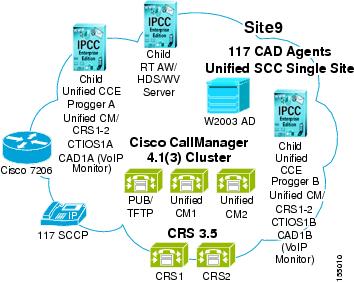
Table 2-10 lists the equipment and hardware platforms used in Site7. Use the reference information in the table to access corresponding software versions and model numbers.
Figure 2-18 shows the physical topology of Site9 displaying all the equipment listed in Table 2-8.
Figure 2-18 Site9 Physical Topology
Test Bed 2: Unified CVP Test Sites
The following six sites make up the multisite centralized and multisite distributed WAN configurations for testing Unified CVP call flows in Test Bed 2:
•
•
•
•
•
•
See Topology of Unified CVP Sites for a complete map of the six sites, their individual topologies, and the relationship between the sites. See Unified CVP Site Definitions for more information on the individual sites in Test Bed 2.
Site Relationships and Call Routing
Listed below are the relationships of the six sites and the call routing deployed in Test Bed 2.
Multisite Centralized Site Relationships
•
•
•
Multisite Distributed Site Relationships
•
•
Call Routing
•
•
•
"Tested Call Flows" discusses these call flows in greater detail.
Topology of Unified CVP Sites
The topology and relationships of the six Unified CVP sites, where Unified CCE with Unified CVP is deployed, is shown in Figure 2-19:
Figure 2-19 Unified CVP Sites in Test Bed 2
Snapshot of Unified CVP Sites Components
Table 2-11 provides a comprehensive view of the different components deployed at the various Unified CVP sites. For specific component names and quantities, see the individual site descriptions in this section.
Note
Unified CVP Site Definitions
The following section describes the sites that were created to deploy the various test deployment models in Test Bed 2 for testing Unified CVP Post-Routed call flows. Each topic in this section defines the design characteristics of an individual site and includes logical and physical topology maps and a site equipment table.
Side A:
•
•
–
–
–
–
•
•
Side B:
•
•
–
–
–
–
•
•
•
Site1: Data Center
Site Profile
Site1 is the hub and the data center in a multisite centralized configuration along with Site5 as its backup data center and redundant hub. It also participates in the multisite distributed WAN configuration.
The test site is deployed as follows:
•
–
•
–
•
–
–
–
•
–
–
–
a.
b.
c.
d.
–
–
–
–
•
–
•
–
•
–
–
–
–
–
–
•
–
–
–
Figure 2-20 shows the logical topology of Site1.
Figure 2-20 Site1 Logical Topology
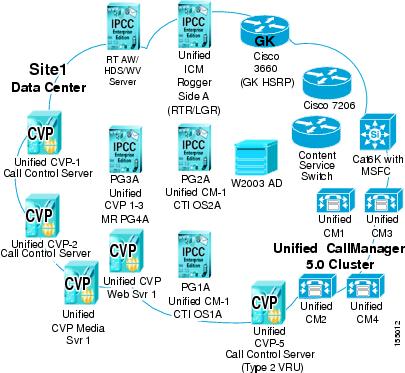
Table 2-12 lists the equipment and hardware platforms used in Site1. Use the reference information in the table to access corresponding software versions and model numbers.
Table 2-12 Site1 Equipment List
Access Switch
Catalyst 6509
1
Alarm Tracker
MCS-7835-2.4-EVV1
1
Unified CallManager
MCS-7845-H1-IPC1
4
Cisco Content Switch (CSS)
CSS 11500
1
CiscoWorks Management Center
MCS-7835-2.4-EVV1
1
CiscoWorks Management Center for Cisco Security Agent and Cisco Security Agent
Unified CVP Call Control Server
MCS-7845-H1-CC1
3
Unified CVP Web Server/HTTP Media Server
MCS-7835-2.4-EVV1
2
Gatekeeper (HSRP cluster)
Cisco 3660
2
Generic PG
MCS-7845-H1-CC1
3
Unified ICM Rogger
MCS-7845-H1-CC1
1
Unified IP Phones
Unified IP Phones 7960
2
Music On Hold (MOH)
MCS-7845-H1-IPC1
1
RTAW /HDS / WebView
MCS-7835-2.4-EVV1
1
WAN Router
Cisco 7206VXR
1
Windows 2003 AD
MCS-7845-1400
1
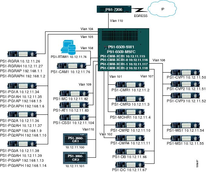
Figure 2-21 shows the physical topology of Site1 displaying the equipment listed in Table 2-11.
Figure 2-21 Site1 Physical Topology
Site3: Distribution Center
Site Profile
Site3 is a distribution center in the multisite centralized configuration of this test bed. It participates in the multisite distributed WAN configuration.
The test site is deployed as follows:
•
–
–
•
–
–
•
–
•
–
–
–
–
–
–
–
•
–
–
•
–
–
Figure 2-22 shows the logical topology of Site3.
Figure 2-22 Site3 Logical Topology
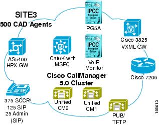
Table 2-13 shows the equipment and hardware platforms used in Site3. Use the reference information in the table to access corresponding software versions and model numbers.
Figure 2-23 shows the physical topology of Site3 displaying the equipment listed in Table 2-13.
Figure 2-23 Site3 Physical Topology
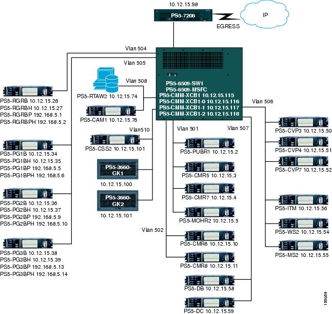
Site5: Data Center
Site Profile
Site5 is the backup data center and hub of Site1 in a multisite centralized configuration. It participates in the multisite distributed WAN configuration.
The test site is deployed as follows:
•
–
•
–
•
–
–
•
–
–
–
a.
b.
c.
d.
–
–
–
–
•
–
•
–
•
–
–
–
–
–
–
•
–
–
Figure 2-24 shows the logical topology of Site5.
Figure 2-24 Site5 Logical Topology
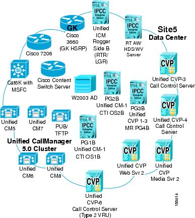
Table 2-14 lists the equipment and hardware platforms used in Site5. Use the reference information in the table to access corresponding software versions and model numbers.
Figure 2-25 shows the physical topology of Site5 displaying the equipment listed in Table 2-15.
Figure 2-25 Site5 Physical Topology
Site6: Mid-Atlantic Retail Center
Site Profile
Site6 is a remote retail site in a multisite centralized configuration in this test bed. It participates in the multisite distributed WAN configuration. The test site is deployed as follows:
•
–
–
–
•
–
–
•
–
•
–
–
–
–
•
–
–
•
–
–
Figure 2-26 shows the logical topology of Site6.
Figure 2-26 Site6 Logical Topology
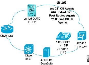
Table 2-15 lists the equipment and hardware platforms used in Site6. Use the reference information in the table to access corresponding software versions and model numbers.
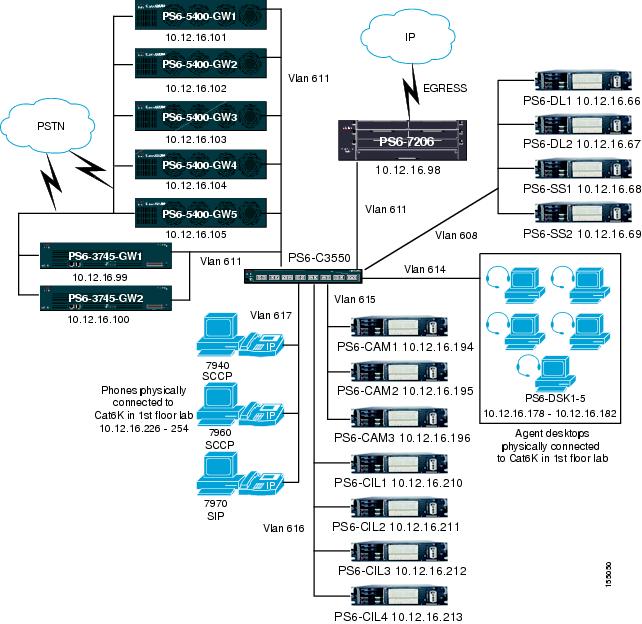
Figure 2-27 shows the physical topology of Site6 displaying the equipment listed in Table 2-16.
Figure 2-27 Site6 Physical Topology
Site7: North-Central Retail Center
Site Profile
Site7 is a medium remote retail site in a multisite centralized configuration in this test bed. It participates in the multisite distributed WAN configuration.
The test site is deployed as follows:
•
–
–
•
–
–
•
–
–
–
–
–
•
–
–
•
–
–
Figure 2-28 shows the logical topology of Site7.
Figure 2-28 Site7 Logical Topology
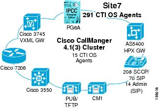
Table 2-16 lists the equipment and hardware platforms used in Site7. Use the reference information in the table to access corresponding software versions and model numbers.
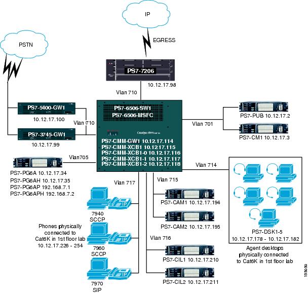
Figure 2-29 shows the physical topology of Site7 displaying all the equipment listed in Table 2-17.
Figure 2-29 Site7 Physical Topology
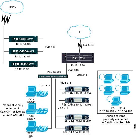
Site8: South-Central Retail Center
Site Profile
Site8 is a remote retail site in a multisite centralized configuration in this test bed. It participates in the multisite distributed WAN configuration.
The test site is deployed as follows:
•
–
–
•
–
–
•
–
•
–
–
•
–
–
•
–
–
Figure 2-30 shows the logical topology of Site8.
Figure 2-30 Site8 Logical Topology
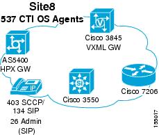
Table 2-17 lists the equipment and hardware platforms used in Site8. Use the reference information in the table to access corresponding software versions and model numbers.
Figure 2-31 shows the physical topology of Site8 displaying all the equipment listed in Table 2-18.
Figure 2-31 Site8 Physical Topology
 Feedback