FlexPod Datacenter for SAP Solution with Cisco Nexus 9000 Series Switches and NetApp AFF A-Series and IP-Based Storage
Available Languages

FlexPod Datacenter for SAP Solution with Cisco Nexus 9000 Series Switches and NetApp AFF A-Series and IP-Based Storage
Design and Deployment Guide for FlexPod Datacenter for SAP Solution with Cisco 9000 Series Switches and NetApp AFF A-Series and IP-Based Storage
Last Updated: July 13, 2017

About the Cisco Validated Design (CVD) Program
The CVD program consists of systems and solutions designed, tested, and documented to facilitate faster, more reliable, and more predictable customer deployments. For more information visit
http://www.cisco.com/go/designzone.
ALL DESIGNS, SPECIFICATIONS, STATEMENTS, INFORMATION, AND RECOMMENDATIONS (COLLECTIVELY, "DESIGNS") IN THIS MANUAL ARE PRESENTED "AS IS," WITH ALL FAULTS. CISCO AND ITS SUPPLIERS DISCLAIM ALL WARRANTIES, INCLUDING, WITHOUT LIMITATION, THE WARRANTY OF MERCHANTABILITY, FITNESS FOR A PARTICULAR PURPOSE AND NONINFRINGEMENT OR ARISING FROM A COURSE OF DEALING, USAGE, OR TRADE PRACTICE. IN NO EVENT SHALL CISCO OR ITS SUPPLIERS BE LIABLE FOR ANY INDIRECT, SPECIAL, CONSEQUENTIAL, OR INCIDENTAL DAMAGES, INCLUDING, WITHOUT LIMITATION, LOST PROFITS OR LOSS OR DAMAGE TO DATA ARISING OUT OF THE USE OR INABILITY TO USE THE DESIGNS, EVEN IF CISCO OR ITS SUPPLIERS HAVE BEEN ADVISED OF THE POSSIBILITY OF SUCH DAMAGES.
THE DESIGNS ARE SUBJECT TO CHANGE WITHOUT NOTICE. USERS ARE SOLELY RESPONSIBLE FOR THEIR APPLICATION OF THE DESIGNS. THE DESIGNS DO NOT CONSTITUTE THE TECHNICAL OR OTHER PROFESSIONAL ADVICE OF CISCO, ITS SUPPLIERS OR PARTNERS. USERS SHOULD CONSULT THEIR OWN TECHNICAL ADVISORS BEFORE IMPLEMENTING THE DESIGNS. RESULTS MAY VARY DEPENDING ON FACTORS NOT TESTED BY CISCO.
CCDE, CCENT, Cisco Eos, Cisco Lumin, Cisco Nexus, Cisco StadiumVision, Cisco TelePresence, Cisco WebEx, the Cisco logo, DCE, and Welcome to the Human Network are trademarks; Changing the Way We Work, Live, Play, and Learn and Cisco Store are service marks; and Access Registrar, Aironet, AsyncOS, Bringing the Meeting To You, Catalyst, CCDA, CCDP, CCIE, CCIP, CCNA, CCNP, CCSP, CCVP, Cisco, the Cisco Certified Internetwork Expert logo, Cisco IOS, Cisco Press, Cisco Systems, Cisco Systems Capital, the Cisco Systems logo, Cisco Unified Computing System (Cisco UCS), Cisco UCS B-Series Blade Servers, Cisco UCS C-Series Rack Servers, Cisco UCS S-Series Storage Servers, Cisco UCS Manager, Cisco UCS Management Software, Cisco Unified Fabric, Cisco Application Centric Infrastructure, Cisco Nexus 9000 Series, Cisco Nexus 7000 Series. Cisco Prime Data Center Network Manager, Cisco NX-OS Software, Cisco MDS Series, Cisco Unity, Collaboration Without Limitation, EtherFast, EtherSwitch, Event Center, Fast Step, Follow Me Browsing, FormShare, GigaDrive, HomeLink, Internet Quotient, IOS, iPhone, iQuick Study, LightStream, Linksys, MediaTone, MeetingPlace, MeetingPlace Chime Sound, MGX, Networkers, Networking Academy, Network Registrar, PCNow, PIX, PowerPanels, ProConnect, ScriptShare, SenderBase, SMARTnet, Spectrum Expert, StackWise, The Fastest Way to Increase Your Internet Quotient, TransPath, WebEx, and the WebEx logo are registered trademarks of Cisco Systems, Inc. and/or its affiliates in the United States and certain other countries.
All other trademarks mentioned in this document or website are the property of their respective owners. The use of the word partner does not imply a partnership relationship between Cisco and any other company. (0809R)
© 2017 Cisco Systems, Inc. All rights reserved.
Table of Contents
Names, Terms, and Definitions Used in this Document
Cisco Unified Computing System
NetApp All Flash FAS and ONTAP
Hardware and Software Components
SAP HANA Disaster Recovery with Asynchronous Storage Replication
SAP HANA Solution Implementations
SAP HANA System on a Single Host - Scale-Up (Bare Metal or Virtualized)
SAP HANA System on Multiple Hosts Scale-Out
Hardware Requirements for the SAP HANA Database
Network Configuration for Management Pod
Dual-Homed FEX Topology (Active/Active FEX Topology)
Cisco Nexus 9000 Series Switches─Network Initial Configuration Setup
Enable Appropriate Cisco Nexus 9000 Series Switches - Features and Settings
Create VLANs for Management Traffic
Configure Virtual Port Channel Domain
Configure Network Interfaces for the VPC Peer Links
Configure Network Interfaces to Cisco UCS C220 Management Server
Configure Network Interfaces for Out of Band Management Plane Access
Direct Connection of Management Pod to FlexPod Infrastructure
Uplink into Existing Network Infrastructure
Management Server Installation
Cisco UCS VIC1325 vNIC Configuration
Set Up Management Networking for ESXi Hosts
Set Up VMkernel Ports and Virtual Switch
FlexPod Network Configuration for SAP HANA
Cisco Nexus 9000 Series Switch ─ Network Initial Configuration Setup
Enable Appropriate Cisco Nexus 9000 Series Switches ─ Features and Settings
Cisco Nexus 9000 A and Cisco Nexus 9000 B
Create VLANs for SAP HANA Traffic
Cisco Nexus 9000 A and Cisco Nexus 9000 B
Create VLANs for Virtualized SAP HANA (vHANA) Traffic
Cisco Nexus 9000 A and Cisco Nexus 9000 B
Configure Virtual Port-Channel Domain
Configure Network Interfaces for the VPC Peer Links
Configure Network Interfaces to NetApp Storage for Data Traffic
Configure Network Interfaces with Cisco UCS Fabric Interconnect
Configure Additional Uplinks to Cisco UCS Fabric Interconnects
(Optional) Configure Network Interfaces for SAP HANA Backup/Data Source/Replication
Cisco Nexus 9000 A and Cisco Nexus 9000 B
(Optional) Management Plane Access for Cisco UCS Servers and VMs
Cisco Nexus 9000 A and Cisco Nexus 9000 B
Direct Connection of FlexPod Infrastructure to Management Pod
Uplink into Existing Network Infrastructure
Cisco UCS Solution for SAP HANA TDI
Cisco UCS Server Configuration
Initial Setup of Cisco UCS 6332 Fabric Interconnect
Cisco UCS 6332 Fabric Interconnect A
Cisco UCS 6332 Fabric Interconnect B
Upgrade Cisco UCS Manager Software to Version 3.1(2f)
Add Block of IP Addresses for KVM Access
Cisco UCS Blade Chassis Connection Options
Enable Server and Uplink Ports
Acknowledge Cisco UCS Chassis and Rack-Mount Servers
Create Uplink Port Channels to Cisco Nexus Switches
Create Server Pool Policy Qualifications
Create Local Disk Configuration Policy (Optional)
Update Default Maintenance Policy
Set Jumbo Frames in Cisco UCS Fabric
Create vNIC template for Network (PXE Boot)
Create vNIC template for Internal Network (Server-Server)
Create vNIC Template for Storage NFS Data Network
Create vNIC Template for Storage NFS Log Network
Create vNIC Template for Admin Network
Create vNIC Template for AppServer Network
Create vNIC Template for Backup Network
Create vNIC Template for Access Network
Create vNIC template for DataSource Network
Create vNIC Template for Replication Network
Create vNIC Template for normal NFS traffic
Create vNIC Template for iSCSI via Fabric A
Create vNIC Template for iSCSI via Fabric B
vNIC Templates Overview for SAP HANA
Create vNIC/vHBA Placement Policy
Create Service Profile Templates Bare Metal SAP HANA Scale-Out
Create Service Profile Templates Bare Metal SAP HANA iSCSI
Create Service Profile from the Template
Create Service Profile Templates Bare Metal SAP HANA Scale-Up
Service Profile for Virtualized SAP HANA (vHANA) Hosts
(Optional) Create New Organization
Create IQN Pools for iSCSI Boot
Create IP Pools for iSCSI Boot
Create Additional MAC Pools for the new vHANA Pool
Create Service Profile Templates
Preparation of PXE Boot Environment
Configure the /etc/hosts File of the Management Stations
Mount Volume for PXE Boot Configuration
Configuration of the DHCP Server for PXE Boot
Operating System Installation SUSE SLES12SP2
PXE Boot Preparation for SUSE OS Installation
Create Swap Partition in a File
Operating System Configuration for SAP HANA
Post Installation OS Customization
Operating System Installation Red Hat Enterprise Linux 7.2
Post Installation OS Customization
Set Up Management Networking for ESXi Hosts
Log in to VMware ESXi Hosts Using a HTML5 Browser
Set Up VMkernel Ports and Virtual Switch
Complete Configuration Worksheet
Set Auto-Revert on Cluster Management
Set Up Management Broadcast Domain
Set Up Service Processor Network Interface
Disable Flow Control on 40GbE Ports
Configure Network Time Protocol
Configure Simple Network Management Protocol
Enable Cisco Discovery Protocol
Configure SVM for the Infrastructure
Create SVM for the Infrastructure
Create Export Policies for the Root Volumes
Add Infrastructure SVM Administrator
Create Export Policies for the Infrastructure SVM
Create Block Protocol (iSCSI) Service
Create Export Policies for the Root Volumes
Create Export Policies for the HANA SVM
Create NFS LIF for SAP HANA Data
Create NFS LIF for SAP HANA Log
Storage Provisioning for SAP HANA
Configuring SAP HANA Single-Host Systems
Configuration Example for a SAP HANA Single-Host System
Create Data Volume and Adjust Volume Options
Create a Log Volume and Adjust the Volume Options
Create a HANA Shared Volume and Qtrees and Adjust the Volume Options
Update the Load-Sharing Mirror Relation
Configuration for SAP HANA Multiple-Host Systems
Configuration Example for a SAP HANA Multiple-Host Systems
Create Data Volumes and Adjust Volume Options
Create Log Volume and Adjust Volume Options
Create HANA Shared Volume and Qtrees and Adjust Volume Options
Update Load-Sharing Mirror Relation
Create a SUSE Virtual Machine for Virtualized SAP HANA (vHANA)
ESXi 6.5 SUSE Linux Enterprise Server 12 SP2 Installation
RHEL 7.2 Installation on ESXi 6.5
Deploy vHANA from the Template
High-Availability (HA) Configuration for Scale-Out
High-Availability Configuration
Enable the SAP HANA Storage Connector API
Configure the System for Capturing Kernel Core Dumps
Test Local Kernel Core Dump Capture
OS Settings for Console Redirection
Cisco Nexus 9000 Example Configurations of FlexPod for SAP HANA.
FlexPod is a defined set of hardware and software that serves as an integrated foundation for virtualized and nonvirtualized data center solutions. It provides a pre-validated, ready-to-deploy infrastructure that reduces the time and complexity involved in configuring and validating a traditional data center deployment. The FlexPod Datacenter solution for SAP HANA includes NetApp storage, NetApp ONTAP, Cisco Nexus® networking, the Cisco Unified Computing System (Cisco UCS), and VMware vSphere software in a single package.
The design is flexible enough that the networking, computing, and storage can fit in one data center rack and can be deployed according to a customer's data center design. A key benefit of the FlexPod architecture is the ability to customize or "flex" the environment to suit a customer's requirements. A FlexPod can easily be scaled as requirements and demand change. The unit can be scaled both up (adding resources to a FlexPod unit) and out (adding more FlexPod units).
The reference architecture detailed in this document highlights the resiliency, cost benefit, and ease of deployment of an IP-based storage solution. A storage system capable of serving multiple protocols across a single interface allows for customer choice and investment protection because it truly a wire-once architecture. The solution is designed to host scalable SAP HANA workloads.
SAP HANA is SAP SE’s implementation of in-memory database technology. A SAP HANA database takes advantage of low cost main memory (RAM), the data-processing capabilities of multicore processors, and faster data access to provide better performance for analytical and transactional applications. SAP HANA offers a multi-engine query-processing environment that supports relational data with both row-oriented and column-oriented physical representations in a hybrid engine. It also offers graph and text processing for semi-structured and unstructured data management within the same system.
With the introduction of SAP HANA TDI for shared infrastructure, the FlexPod solution provides you the advantage of having the compute, storage, and network stack integrated with the programmability of the Cisco UCS. SAP HANA TDI enables organizations to run multiple SAP HANA production systems in one FlexPod solution. It also enables customers to run the SAP applications servers and the SAP HANA database on the same infrastructure.
Introduction
Cisco® Validated Designs (CVDs) include systems and solutions that are designed, tested, and documented to facilitate and improve customer deployments. These designs incorporate a wide range of technologies and products into a portfolio of solutions that have been developed to address the business needs of customers. Cisco and NetApp® have partnered to deliver FlexPod®, which serves as the foundation for a variety of workloads and enables efficient architectural designs that are based on customer requirements. A FlexPod solution is a validated approach for deploying Cisco and NetApp technologies as a shared cloud infrastructure. This document describes the architecture and deployment procedures for the SAP HANA tailored data center integration (TDI) option for FlexPod infrastructure composed of Cisco compute and switching products, VMware virtualization, and NetApp NFS and iSCSI-based storage components. The intent of this document is to show the configuration principles with the detailed configuration steps.
For more information about SAP HANA, see the SAP help portal.
Audience
The intended audience for this document includes, but is not limited to, sales engineers, field consultants, professional services, IT managers, partner engineering, and customers deploying the FlexPod Datacenter solution for SAP HANA with NetApp ONTAP®. External references are provided wherever applicable, but readers are expected to be familiar with the technology, infrastructure, and database security policies of the customer installation.
Purpose of this Document
This document describes the steps required to deploy and configure a FlexPod Datacenter Solution for SAP HANA. Cisco’s validation provides further confirmation of component compatibility, connectivity, and the correct operation of the entire integrated stack. This document showcases a variant of the cloud architecture for SAP HANA. While readers of this document are expected to have sufficient knowledge to install and configure the products used, configuration details that are important to the deployment of this solution are provided in this CVD.
Names, Terms, and Definitions Used in this Document
SAP HANA SAP HANA Database
TDI Tailored Data Center Integration
KPI Key Performance Indicators
SoH SAP Business Suite on SAP HANA Database
BWoH SAP Business Warehouse on SAP HANA Database
UCS Cisco Unified Computing System
GbE Gigabit Ethernet
SLES SUSE Linux Enterprise Server
SLES4SAP SUSE Linux Enterprise Server for SAP Applications
GB Gigabyte
TB Terabyte
IVB Ivy Bridge
DB Database
OS Operating System
IOM UCS IO-Module
FI UCS Fabric Interconnect
vNIC Virtual Network Interface Card
RAM Server Main Memory
SID System Identifier
The FlexPod Datacenter Solution for SAP HANA is composed of Cisco UCS servers, Cisco Nexus switches, NetApp AFF storage, and VMware vSphere. This section describes the main features of these different solution components.
Cisco Unified Computing System
The Cisco Unified Computing System is a state-of-the-art data center platform that unites computing, network, storage access, and virtualization into a single cohesive system.
The main components of the Cisco Unified Computing System are:
· Computing - The system is based on an entirely new class of computing system that incorporates rack mount and blade servers based on Intel Xeon Processor E5 and E7. The Cisco UCS Servers offer the patented Cisco Extended Memory Technology to support applications with large datasets and allow more virtual machines per server.
· Network - The system is integrated onto a low-latency, lossless, 10-Gbps unified network fabric. This network foundation consolidates LANs, SANs, and high-performance computing networks which are separate networks today. The unified fabric lowers costs by reducing the number of network adapters, switches, and cables, and by decreasing the power and cooling requirements.
· Virtualization - The system unleashes the full potential of virtualization by enhancing the scalability, performance, and operational control of virtual environments. Cisco security, policy enforcement, and diagnostic features are now extended into virtualized environments to better support changing business and IT requirements.
· Storage access - The system provides consolidated access to both SAN storage and Network Attached Storage (NAS) over the unified so that the Cisco UCS can access storage over Ethernet (NFS or iSCSI). This feature provides customers with choice for storage access and investment protection. In addition, the server administrators can pre-assign storage-access policies for system connectivity to storage resources, simplifying storage connectivity, and management for increased productivity.
The Cisco Unified Computing System is designed to deliver:
· A reduced Total Cost of Ownership (TCO) and increased business agility.
· Increased IT staff productivity through just-in-time provisioning and mobility support.
· A cohesive, integrated system, which unifies the technology in the data center.
· Industry standards supported by a partner ecosystem of industry leaders.
NetApp All Flash FAS and ONTAP
NetApp All Flash FAS (AFF) systems address enterprise storage requirements with high performance, superior flexibility, and best-in-class data management. Built on NetApp ONTAP data management software, AFF systems speed up business without compromising on the efficiency, reliability, or flexibility of IT operations. As an enterprise-grade all-flash array, AFF accelerates, manages, and protects business-critical data and enables an easy and risk-free transition to flash for your data center.
Designed specifically for flash, the NetApp AFF A series all-flash systems deliver industry-leading performance, capacity density, scalability, security, and network connectivity in dense form factors. At up to 7M IOPS per cluster with submillisecond latency, they are the fastest all-flash arrays built on a true unified scale-out architecture. As the industry’s first all-flash arrays to provide both 40 Gigabit Ethernet (40GbE) and 32Gb Fibre Channel connectivity, AFF A series systems eliminate the bandwidth bottlenecks that are increasingly moved to the network from storage as flash becomes faster and faster.
AFF comes with a full suite of acclaimed NetApp integrated data protection software. Key capabilities and benefits include the following:
· Native space efficiency with cloning and NetApp Snapshot® copies, which reduces storage costs and minimizes performance effects.
· Application-consistent backup and recovery, which simplifies application management.
· NetApp SnapMirror® replication software, which replicates to any type of FAS/AFF system—all flash, hybrid, or HDD and on the premises or in the cloud— and reduces overall system costs.
AFF systems are built with innovative inline data reduction technologies:
· Inline data compaction technology uses an innovative approach to place multiple logical data blocks from the same volume into a single 4KB block.
· Inline compression has a near-zero performance effect. Incompressible data detection eliminates wasted cycles.
· Enhanced inline deduplication increases space savings by eliminating redundant blocks.
This version of FlexPod introduces the NetApp AFF A300 series unified scale-out storage system. This controller provides the high-performance benefits of 40GbE and all flash SSDs and occupies only 3U of rack space. Combined with a disk shelf containing 3.8TB disks, this solution provides ample horsepower and over 90TB of raw capacity while taking up only 5U of valuable rack space. The AFF A300 features a multiprocessor Intel chipset and leverages high-performance memory modules, NVRAM to accelerate and optimize writes, and an I/O-tuned PCIe gen3 architecture that maximizes application throughput. The AFF A300 series comes with integrated unified target adapter (UTA2) ports that support 16Gb Fibre Channel, 10, and FCoE. In addition 40GBE add-on cards are available.
Architecture
The FlexPod Datacenter solution for SAP HANA with NetApp All Flash FAS storage provides an end-to-end architecture with Cisco, NetApp and VMware technologies that demonstrate support for multiple SAP and SAP HANA workloads with high availability and server redundancy. The architecture uses UCS 3.1(2f) with combined Cisco UCS B-Series and C-Series Servers with NetApp AFF A300 series storage attached to the Cisco Nexus 93180YC switches for NFS access and iSCSI. The Cisco UCS C-Series Rack Servers are connected directly to Cisco UCS Fabric Interconnect with single-wire management feature. This infrastructure is deployed to provide PXE and iSCSI boot options for hosts with file-level and block-level access to shared storage. VMware vSphere 6.5 is used as server virtualization architecture. The reference architecture reinforces the “wire-once” strategy, because when the additional storage is added to the architecture, no re-cabling is required from hosts to the Cisco UCS Fabric Interconnect.
Figure 1 shows the FlexPod Datacenter reference architecture for SAP HANA workload, described in this Cisco Validation Design. It highlights the FlexPod hardware components and the network connections for a configuration with IP-based storage.
Figure 1 FlexPod Datacenter Reference Architecture for SAP HANA
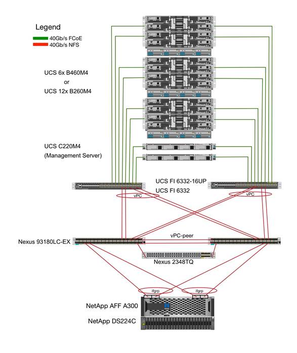
Figure 1 includes the following:
· Cisco Unified Computing System
- 2 x Cisco UCS 6332 /6332-16UP 32 x 40Gb/s / 16+24 16x 10/16Gb + 24x 40Gb/s
- 2 x Cisco UCS 5108 Blade Chassis with 2 x Cisco UCS 2304 Fabric Extenders with 4x 40 Gigabit Ethernet interfaces
- 2 x Cisco UCS B460 M4 High-Performance Blade Servers with 2x Cisco UCS Virtual Interface Card (VIC) 1380 and 2x Cisco UCS Virtual Interface Card (VIC) 1340
- 2 x Cisco UCS B260 M4 High-Performance Blade Servers with 1x Cisco UCS Virtual Interface Card (VIC) 1380 and 1x Cisco UCS Virtual Interface Card (VIC) 1340
- 1 x Cisco UCS C460 M4 High-Performance Rack-Mount Servers with 2x Cisco UCS Virtual Interface Card (VIC) 1385.
- 4 x Cisco UCS B200 M4 High-Performance Blade Servers with Cisco UCS Virtual Interface Card (VIC) 1340
- 1 x Cisco UCS C220 M4 High-Performance Blade Servers with Cisco UCS Virtual Interface Card (VIC) 1385
- 1 x Cisco UCS C240 M4 High-Performance Blade Servers with Cisco UCS Virtual Interface Card (VIC) 1385
· Cisco Nexus Switches
- 2 x Cisco Nexus 93180LC-PX Switch for 40/100 Gigabit Ethernet connectivity between the two UCS Fabric Interconnects
· NetApp AFF A300 Storage
- NetApp AFF A300 Storage system using ONTAP 9.1/9.2
- 1 x NetApp Disk Shelf DS224C with 24x 3.8TB SSD
- Server virtualization is achieved by VMware vSphere 6.5.
Although this is the base design, each of the components can be scaled easily to support specific business requirements. Additional servers or even blade chassis can be deployed to increase compute capacity without additional Network components. Two Cisco UCS 6332-16UP -Port Fabric interconnect can support up to:
· 20 Cisco UCS B-Series B460 M4 or 40 B260 M4 Server with 10 Blade Server Chassis
· 20 Cisco UCS C460 M4 Sever
· 40 Cisco UCS C220 M4/C240 M4 Server
For every twelve Cisco UCS Server, one NetApp AFF A300 HA pair with ONTAP is required to meet the SAP HANA storage performance. While adding compute and storage for scaling, it is required to increase the network bandwidth between Cisco UCS Fabric Interconnect and Cisco Nexus 9000 switch. Addition of each NetApp Storage requires additional two 40 GbE connectivity from each Cisco UCS Fabric Interconnect to Cisco Nexus 9000 switches.
The number of Cisco UCS C-Series or Cisco UCS B-Series Servers and the NetApp FAS storage type depends on the number of SAP HANA instances. SAP specifies the storage performance for SAP HANA, based on a per server rule independent of the server size. In other words, the maximum number of servers per storage will remain the same if you want to use Cisco UCS B200 M4 with 192GB physical memory or Cisco UCS B460 M4 with 2TB physical memory.
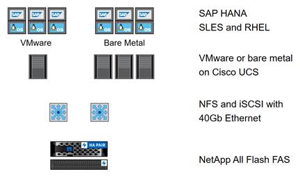
Hardware and Software Components
This architecture is based on and supports the following hardware and software components:
· SAP HANA
- SAP Business Suite on HANA or SAP Business Warehouse on HANA
- S/4HANA or BW/4HANA
- SAP HANA single-host or multiple-host configurations
· Operating System
- SUSE Linux Enterprise (SLES), SUSE Linux Enterprise for SAP (SLES for SAP)
- RedHat Enterprise Linux
· Cisco UCS Server
- Bare Metal
- VMware
· Network
- 40GbE end-to-end
- NFS for SAP HANA data access
- NFS or iSCSI for OS boot
· Storage
- NetApp All Flash FAS
Figure 2 shows on overview of the hardware and software components.
Figure 2 Hardware and Software Component Overview
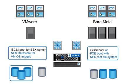
Operating System Provisioning
All operating system images are provisioned from the external NetApp storage, either using NFS or iSCSI.
· VMware ESX
- iSCSI boot
· VMware Linux VMs
- VMDKs in NFS datastore
· Linux on bare metal
- PXE boot and NFS root file system
- iSCSI boot
Figure 3 shows an overview of the different operating system provisioning methods.
Figure 3 Overview Operating System Provisioning
SAP HANA Database Volumes
All SAP HANA database volumes, the data, the log, and the shared volumes are mounted with NFS from the central storage. The storage and Linux OS configuration is identical for SAP HANA running on VMware or running on a bare metal server.
Figure 4 shows an overview of the SAP HANA database volumes.
Figure 4 SAP HANA Database Volumes
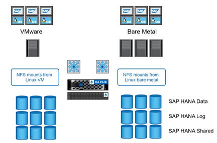
Figure 5 shows a block diagram of a complete SAP Landscape built using the FlexPod architecture. It composed of multiple SAP HANA systems and SAP applications with shared infrastructure as illustrated in the figure. The FlexPod Datacenter reference architecture for SAP solutions supports SAP HANA system in both Scale- Up mode (bare metal/ virtualization) and Scale-Out mode with multiple servers with the shared infrastructures.
Virtualized SAP application servers with VMware vSphere 6.5 allows application servers to run on the same infrastructure as the SAP HANA database. The FlexPod datacenter solution manages the communication between the application server and the SAP HANA database. This approach enhances system performance by improving bandwidth and latency. It also improves system reliability by including the application server in the disaster-tolerance solution with the SAP HANA database.
Figure 5 Shared Infrastructure Block Diagram
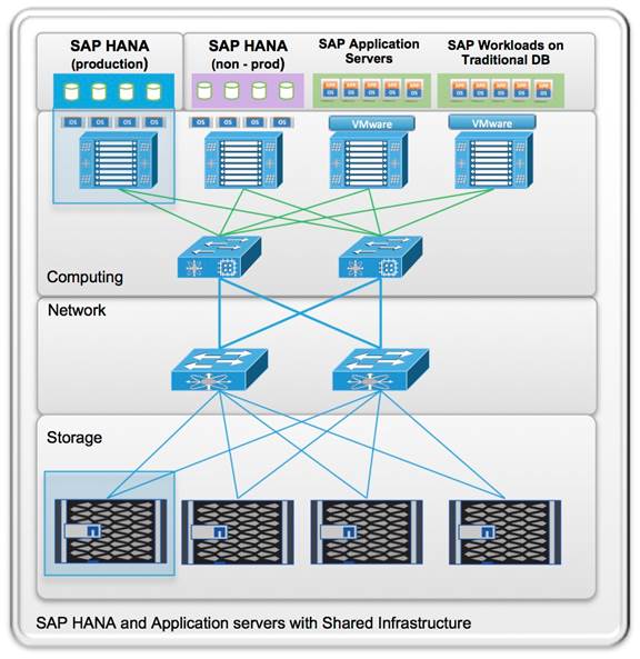
The FlexPod architecture for SAP HANA TDI allows to run other workloads on the same infrastructure, as long as the rules for workload isolation are considered.
You can run the following workloads on the FlexPod architecture:
1. Production SAP HANA databases
2. SAP application servers
3. Non-production SAP HANA databases
4. Production and non-production SAP systems on traditional databases
5. Non-SAP workloads
In order to ensure that the storage KPIs for SAP HANA production databases are fulfilled, the SAP HANA production databases must have dedicated storage controller of a NetApp FAS Storage HA pair. SAP application servers could share the same storage controller with the production SAP HANA databases.
This document describes in detail the procedure for the reference design and outlines the network, compute and storage configurations and deployment process for running SAP HANA on FlexPod platform. This document does not describe the procedure for deploying SAP applications.
SAP HANA Data Protection
The FlexPod solution can be extended with additional software and hardware components to cover data protection, backup and recovery, and disaster recovery. The following chapter provides an overview of how to dramatically enhance SAP HANA backup and disaster recovery using the NetApp Snap Creator Plug-In for SAP HANA.
To support future SAP HANA features and deliver a unified backup and data protection solution for all major databases, NetApp is planning to integrate the data protection solutions for SAP HANA into the new data protection product line, SnapCenter. Starting with the upcoming SnapCenter version 3.0, customers can use SnapCenter to integrate SAP HANA data protection into their overall data management operations.
SAP HANA Backup
Storage-based Snapshot backups are a fully supported and integrated backup method available for SAP HANA.
Storage-based Snapshot backups are implemented with the NetApp Snap Creator plug-in for SAP HANA, which creates consistent Snapshot backups by using the interfaces provided by the SAP HANA database. Snap Creator registers the Snapshot backups in the SAP HANA backup catalog so that they are visible within the SAP HANA studio and can be selected for restore and recovery operations.
By using NetApp SnapVault® software, the Snapshot copies that were created on the primary storage can be replicated to the secondary backup storage controlled by Snap Creator. Different backup retention policies can be defined for backups on the primary storage and backups on the secondary storage. The Snap Creator Plug-In for SAP HANA manages the retention of Snapshot copy-based data backups and log backups, including housekeeping of the backup catalog. The Snap Creator plug-in for SAP HANA also allows the execution of a block integrity check of the SAP HANA database by executing a file-based backup.
The database logs can be backed up directly to the secondary storage by using an NFS mount, as shown in Figure 6.

Storage-based Snapshot backups provide significant advantages compared to file-based backups. The advantages include:
· Faster backup (less than a minute)
· Faster restore on the storage layer (less than a minute)
· No performance effect on the SAP HANA database host, network, or storage during backup
· Space-efficient and bandwidth-efficient replication to secondary storage based on block changes
For detailed information about the SAP HANA backup and recovery solution using Snap Creator, see TR-4313: SAP HANA Backup and Recovery Using Snap Creator.
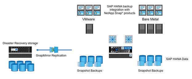
SAP HANA Disaster Recovery with Asynchronous Storage Replication
SAP HANA disaster recovery can be performed either on the database layer by using SAP system replication or on the storage layer by using storage replication technologies. This section provides an overview of disaster recovery solutions based on asynchronous storage replication.
For detailed information about SAP HANA disaster recovery solutions, see TR-4279: SAP HANA Disaster Recovery with Asynchronous Storage Replication Using Snap Creator and SnapMirror.
The same Snap Creator plug-in that is described in the section “SAP HANA Backup” is also used for the asynchronous mirroring solution. A consistent Snapshot image of the database at the primary site is asynchronously replicated to the disaster recovery site by using SnapMirror.
Figure 7 Asynchronous Storage Replication
Management Pod
Comprehensive management is an important element for a FlexPod environment running SAP HANA, especially in a system involving multiple FlexPod platforms. Management pod built to handle this efficiently. It is an optional to build a dedicated Management environment; customer can use their existing Management environment for the same functionality. Management Pod includes (but is not limited to) a pair of Cisco Nexus 9000 Series switches in standalone mode and a pair of Cisco UCS C220 M4 Rack-Mount Servers. The Cisco Nexus switch provides the out-of-band management network. It is recommended to use additional NetApp FAS Storage in the Management Pod for redundancy and failure scenarios. The Cisco UCS C220 M4 Rack-Mount Servers will run ESXi with PXE boot server, vCenter with additional management, and monitor virtual machines.
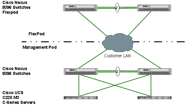
Management Pod switches can connect directly to FlexPod switches or customer’s existing network infrastructure. If customer’s existing network infrastructure is used, the uplink from FlexPod switches are connected same pair of switch as uplink from Management Pod switches as shown in Figure 8.
![]() The customer’s LAN switch must allow all the necessary VLANs for managing the FlexPod environment.
The customer’s LAN switch must allow all the necessary VLANs for managing the FlexPod environment.
Figure 8 Management Pod Using Customer Existing Network
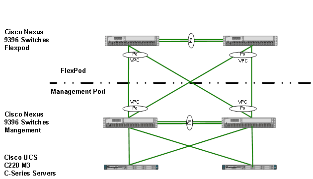
The dedicated Management Pod can directly connect to each FlexPod environment as shown in Figure 9. In this topology, the switches are configured as port-channels for unified management. This CVD describes the procedure for the direct connection option.
Figure 9 Direct connection of Management Pod to FlexPod
SAP HANA Solution Implementations
This section describes the various implementation options and their requirements for a SAP HANA system.
SAP HANA System on a Single Host - Scale-Up (Bare Metal or Virtualized)
A single-host system is the simplest of the installation types. It is possible to run an SAP HANA system entirely on one host and then scale the system up as needed. All data and processes are located on the same server and can be accessed locally. The network requirements for this option minimum one 1-Gb Ethernet (access) and one 10/40-Gb Ethernet storage networks are sufficient to run SAP HANA scale-up. Virtualized SAP HANA Scale-Up system requires dedicated 10/40 Gigabit Ethernet network adapters per virtualized SAP HANA system.
With the SAP HANA TDI option, multiple SAP HANA scale-up systems can be built on a shared infrastructure.
SAP HANA System on Multiple Hosts Scale-Out
SAP HANA Scale-Out option is used if the SAP HANA system does not fit into the main memory of a single server based on the rules defined by SAP. In this method, multiple independent servers are combined to form one system and the load is distributed among multiple servers. In a distributed system, each index server is usually assigned to its own host to achieve maximum performance. It is possible to assign different tables to different hosts (partitioning the database), or a single table can be split across hosts (partitioning of tables). SAP HANA Scale-Out supports failover scenarios and high availability. Individual hosts in a distributed system have different roles master, worker, slave, standby depending on the task.
![]() Some use cases are not supported on SAP HANA Scale-Out configuration and it is recommended to check with SAP whether a use case can be deployed as a Scale-Out solution.
Some use cases are not supported on SAP HANA Scale-Out configuration and it is recommended to check with SAP whether a use case can be deployed as a Scale-Out solution.
The network requirements for this option are higher than for Scale-Up systems. In addition to the client and application access and storage access network, a node-to-node network is necessary. One 10 Gigabit Ethernet (access) and one 10 Gigabit Ethernet (node-to-node) and one 10 Gigabit Ethernet storage networks are required to run SAP HANA Scale-Out system. Additional network bandwidth is required to support system replication or backup capability.
Based on the SAP HANA TDI option for shared storage and shared network, multiple SAP HANA Scale-Out systems can be built on a shared infrastructure.
Hardware Requirements for the SAP HANA Database
Additional information is available at: http://saphana.com.
![]() This document does not cover the updated information published by SAP after Q1/2017.
This document does not cover the updated information published by SAP after Q1/2017.
CPU
SAP HANA2.0 supports servers equipped with Intel Xeon processor E7-8880v3, E7-8890v3, E7-8880v4 or E7-8890v4 CPUs. In addition, the Intel Xeon processor E5-26xx v4 is supported for scale-up systems with the SAP HANA TDI option.
Memory
SAP HANA is supported in the following memory configurations:
· Homogenous symmetric assembly of dual in-line memory modules (DIMMs) for example, DIMM size or speed should not be mixed
· Maximum use of all available memory channels
· Memory per socket up to 768 GB for SAP NetWeaver Business Warehouse (BW) and DataMart
· Memory per socket up to 1024 GB for SAP Business Suite on SAP HANA (SoH) on 2- or 4-socket server
CPU and Memory Combinations
SAP HANA allows for a specific set of CPU and memory combinations. Table 1 describes the list of certified Cisco UCS servers for SAP HANA with supported Memory and CPU configuration for different use cases.
Table 1 List of Cisco UCS Servers Defined in FlexPod Datacenter Solution for SAP
| Cisco UCS Server |
CPU |
Supported Memory
|
Scale UP/ Suite on HANA |
Scale-Out |
| Cisco UCS B200 M4 |
2 x Intel Xeon E5-26xx v4 |
128 GB to 1.5 TB |
Supported |
Not supported |
| Cisco UCS C220 M4 |
2 x Intel Xeon E5-26xx v4 |
128 GB to 1.5 TB |
Supported |
Not supported |
| Cisco UCS C240 M4 |
2 x Intel Xeon E5-26xx v4 |
128 GB to 1.5 TB |
Supported |
Not supported |
| Cisco UCS B260 M4 |
2 x Intel E7-88x0 v4 |
128 GB to 2TB |
Supported |
Not Supported |
| Cisco UCS B460 M4 |
4 x Intel E7-88x0 v4 |
256 GB to 2 TB for BW 256 GB to 4 TB for SoH |
Supported |
Supported |
| Cisco UCS C460 M4 |
4 x Intel E7-88x0 v4 |
256 GB to 2 TB for BW 256 GB to 4 TB for SoH |
Supported |
Supported |
| Cisco C880 M4 |
8x Intel E7-88x0 v4 |
1TB – 4TB for BW 1TB – 8TB for SoH |
Supported |
Supported |
Network
A SAP HANA data center deployment can range from a database running on a single host to a complex distributed system. Distributed systems can get complex with multiple hosts located at a primary site having one or more secondary sites; supporting a distributed multi-terabyte database with full fault and disaster recovery.
SAP HANA has different types of network communication channels to support the different SAP HANA scenarios and setups:
· Client zone: Channels used for external access to SAP HANA functions by end-user clients, administration clients, and application servers, and for data provisioning through SQL or HTTP
· Internal zone: Channels used for SAP HANA internal communication within the database or, in a distributed scenario, for communication between hosts
· Storage zone: Channels used for storage access (data persistence) and for backup and restore procedures
Table 2 lists all the networks defined by SAP or Cisco or requested by customers.
Table 2 List of Known Networks
| Name |
Use Case |
Solutions |
Bandwidth requirements |
| Client Zone Networks |
|||
| Application Server Network |
SAP Application Server to DB communication |
All |
10 or 40 GbE |
| Client Network |
User / Client Application to DB communication |
All |
10 or 40 GbE |
| Data Source Network |
Data import and external data integration |
Optional for all SAP HANA systems |
10 or 40 GbE |
| Internal Zone Networks |
|||
| Inter-Node Network |
Node to node communication within a scale-out configuration |
Scale-Out |
40 GbE |
| System Replication Network |
|
For SAP HANA Disaster Tolerance |
TBD with Customer |
| Storage Zone Networks |
|||
| Backup Network |
Data Backup |
Optional for all SAP HANA systems |
10 or 40 GbE |
| Storage Network |
Node to Storage communication |
All
|
40 GbE |
| Infrastructure Related Networks |
|||
| Administration Network |
Infrastructure and SAP HANA administration |
Optional for all SAP HANA systems |
1 GbE |
| Boot Network |
Boot the Operating Systems via PXE/NFS or iSCSI |
Optional for all SAP HANA systems |
40 GbE |
Details about the network requirements for SAP HANA are available in the white paper from SAP SE at: http://www.saphana.com/docs/DOC-4805.
The network needs to be properly segmented and must be connected to the same core/ backbone switch as shown in Figure 10, based on your customer’s high-availability and redundancy requirements for different SAP HANA network segments.
Figure 10 ![]() High-Level SAP HANA Network Overview
High-Level SAP HANA Network Overview
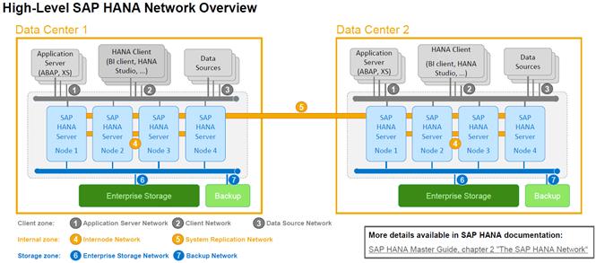
Based on the listed network requirements, every server must be equipped with 2x 10 Gigabit Ethernet for scale-up systems to establish the communication with the application or user (Client Zone) and a 10 GbE Interface for Storage access.
For Scale-Out solutions, an additional redundant network for SAP HANA node to node communication with 10 GbE is required (Internal Zone).
![]() For more information on SAP HANA Network security please refer to SAP HANA Security Guide.
For more information on SAP HANA Network security please refer to SAP HANA Security Guide.
Storage
As an in-memory database, SAP HANA uses storage devices to save a copy of the data, for the purpose of startup and fault recovery without data loss. The choice of the specific storage technology is driven by various requirements like size, performance and high availability. To use Storage system in the Tailored Datacenter Integration option, the storage must be certified for SAP HANA TDI option at https://www.sap.com/dmc/exp/2014-09-02-hana-hardware/enEN/enterprise-storage.html.
All relevant information about storage requirements is documented in this white paper: https://www.sap.com/documents/2015/03/74cdb554-5a7c-0010-82c7-eda71af511fa.html.
![]() SAP can only support performance related SAP HANA topics if the installed solution has passed the validation test successfully.
SAP can only support performance related SAP HANA topics if the installed solution has passed the validation test successfully.
Refer to the SAP HANA Administration Guide section 2.8 Hardware Checks for Tailored Datacenter Integration for Hardware check test tool and the related documentation.
Filesystem Layout
Figure 11 shows the file system layout and the required storage sizes to install and operate SAP HANA. For the Linux OS installation (/root) 10 GB of disk size is recommended. Additionally, 50 GB must be provided for the /usr/sap since the volume used for SAP software that supports SAP HANA.
While installing SAP HANA on a host, specify the mount point for the installation binaries (/hana/shared/<sid>), data files (/hana/data/<sid>) and log files (/hana/log/<sid>), where sid is the instance identifier of the SAP HANA installation.
Figure 11 File System Layout for 2 Node Scale-Out System
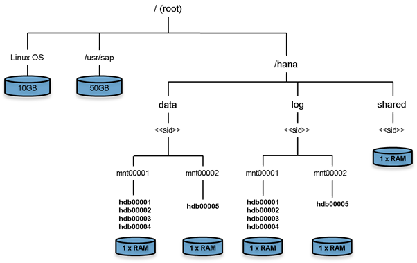
![]() The storage sizing for filesystem is based on the amount of memory equipped on the SAP HANA host.
The storage sizing for filesystem is based on the amount of memory equipped on the SAP HANA host.
Below is a sample filesystem size for a single system with 512GB memory:
Root-FS: 10 GB
/usr/sap: 50 GB
/hana/shared: 1x memory (512 GB)
/hana/data: 1x memory (512 GB)
/hana/log: 1x Memory (512 GB)
In case of distributed installation of SAP HANA Scale-Out, each server will have the following:
Root-FS: 10 GB
/usr/sap: 50 GB
The installation binaries, trace and configuration files are stored on a shared filesystem, which should be accessible for all hosts in the distributed installation. The size of shared filesystem should be equal to the hosts memory for each four hosts.
For example, in a distributed installation with three hosts with 512 GB of memory each, shared file system should be 1 x 512 GB = 512 GB, for 5 hosts with 512 GB of memory each, shared file system should be 2 x 512 GB = 1024GB.
For each SAP HANA host there should be a mount point for data and log volume. The size of the file system for data volume with TDI option is one times the host memory:
/hana/data/<sid>/mntXXXXX: 1x Memory (512 GB)
For solutions based on Intel E7-x890v4 CPU the size of the Log volume must be as follows:
· Half of the server memory for systems ≤ 512 GB memory
· 512 GB for systems with > 512 GB memory
Operating System
The supported operating systems for SAP HANA are as follows:
· SUSE Linux Enterprise Server for SAP Applications
· RedHat Enterprise Linux for SAP HANA
High Availability
· Internal storage: A RAID-based configuration is preferred
· External storage: Redundant data paths, dual controllers, and a RAID-based configuration are required
· Ethernet switches: Two or more independent switches should be used
SAP HANA Scale-Out comes with in integrated high-availability function. If a SAP HANA system is configured with a stand-by node, a failed part of SAP HANA will start on the stand-by node automatically. For automatic host failover, storage connector API must be properly configured for the implementation and operation of the SAP HANA.
For detailed information from SAP see: http://saphana.com or http://service.sap.com/notes.
Software Revisions
Table 3 details the software revisions used for validating various components of the FlexPod Datacenter Reference Architecture for SAP HANA.
| Vendor |
Product |
Version |
Description |
| Cisco |
UCSM |
3.1(2f) |
Cisco UCS Manager |
| Cisco |
UCS 6332-16UP FI |
3.1(2f) |
Cisco UCS Fabric Interconnects |
| Cisco |
UCS 5108 Blade Chassis |
NA |
Cisco UCS Blade Server Chassis |
| Cisco |
UCS 2304XP FEX |
3.1(2f) |
Cisco UCS Fabric Extenders for Blade Server chassis |
| Cisco |
UCS B-Series M4 Servers |
3.1(2f) |
Cisco UCS B-Series M4 Blade Servers |
| Cisco |
UCS VIC 1340/1380 |
4.1.2d |
Cisco UCS VIC 1240/1280 Adapters |
| Cisco |
UCS C220 M4 Servers |
2.0.3e – CIMC C220M4.2.0.3c - BIOS |
Cisco UCS C220 M4 Rack Servers |
| Cisco |
UCS VIC 1335 |
2.1.1.75 |
Cisco UCS VIC Adapter |
| Cisco |
UCS C460 M4 Servers |
2.0.3e – CIMC C460M4.2.0.3c - BIOS |
Cisco UCS C460 M4 Rack Servers |
| Cisco |
UCS VIC 1325 |
2.1.1.75 |
Cisco UCS VIC Adapter |
| Cisco |
UCS C220 M4 Servers |
CIMC 1.5(7a) BIOS 1.5.7.0 |
Cisco UCS C220 M4 Rack Servers for Management |
| Cisco |
Nexus 93180LC Switches |
6.1(2)I2(2a) |
Cisco Nexus 9396x Switches |
| NetApp |
NetApp AFF A300 |
ONTAP 9.1/9.2 |
Operating system version |
| VMware |
ESXi 6.5 |
6.5 |
Hypervisor |
| VMware |
vCenter Server |
6.5 |
VMware Management |
| SUSE |
SUSE Linux Enterprise Server (SLES) |
12 SP1 |
Operating System to host SAP HANA |
| RedHat |
RedHat Enterprise Linux (RHEL) for SAP HANA |
7.2 |
Operating System to host SAP HANA |
Configuration Guidelines
This document provides details for configuring a fully redundant, highly available configuration for a FlexPod unit with ONTAP storage. Therefore, reference is made to which component is being configured with each step, either 01 or 02. For example, node01 and node02 are used to identify the two NetApp storage controllers that are provisioned with this document and Cisco Nexus A and Cisco Nexus B identifies the pair of Cisco Nexus switches that are configured.
The Cisco UCS Fabric Interconnects are similarly configured. Additionally, this document details the steps for provisioning multiple Cisco UCS hosts, and these are identified sequentially: HANA-Server01, HANA-Server02, and so on. Finally, to indicate that you should include information pertinent to your environment in a given step, <text> appears as part of the command structure. See the following example for the network port vlan create command:
Usage:
network port vlan create ?
[-node] <nodename> Node
{ [-vlan-name] {<netport>|<ifgrp>} VLAN Name
| -port {<netport>|<ifgrp>} Associated Network Port
[-vlan-id] <integer> } Network Switch VLAN Identifier
Example:
network port vlan –node <node01> -vlan-name i0a-<vlan id>
This document is intended to enable you to fully configure the customer environment. In this process, various steps require you to insert customer-specific naming conventions, IP addresses, and VLAN schemes, as well as to record appropriate MAC addresses. Table 4 lists the configuration variables that are used throughout this document. This table can be completed based on the specific site variables and used in implementing the document configuration steps.
Table 4 Configuration Variables
| Variable |
Description |
Customer Implementation Value |
| <<var_nexus_mgmt_A_hostname>> |
Cisco Nexus Management A host name |
|
| <<var_nexus_mgmt_A_mgmt0_ip>> |
Out-of-band Cisco Nexus Management A management IP address |
|
| <<var_nexus_mgmt_A_mgmt0_netmask>> |
Out-of-band management network netmask |
|
| <<var_nexus_mgmt_A_mgmt0_gw>> |
Out-of-band management network default gateway |
|
| <<var_nexus_mgmt_B_hostname>> |
Cisco Nexus Management B host name |
|
| <<var_nexus_mgmt_B_mgmt0_ip>> |
Out-of-band Cisco Nexus Management B management IP address |
|
| <<var_nexus_mgmt_B_mgmt0_netmask>> |
Out-of-band management network netmask |
|
| <<var_nexus_mgmt_B_mgmt0_gw>> |
Out-of-band management network default gateway |
|
| <<var_global_ntp_server_ip>> |
NTP server IP address |
|
| <<var_oob_vlan_id>> |
Out-of-band management network VLAN ID |
|
| <<var_admin_vlan_id>> |
Admin network VLAN ID |
|
| <<var_boot_vlan_id>> |
PXE boot network VLAN ID |
|
| <<var_esx_mgmt_vlan_id>> |
ESXi Management Network for Management Server VLAN ID |
|
| <<var_esx_vmotion_vlan_id>> |
ESXi vMotion Network VLAN ID |
|
| <<var_esx_nfs_vlan_id>> |
ESXi NFS Storage Network VLAN ID |
|
| <<var_nexus_vpc_domain_mgmt_id>> |
Unique Cisco Nexus switch VPC domain ID for Management Switch |
|
| <<var_nexus_vpc_domain_id>> |
Unique Cisco Nexus switch VPC domain ID |
|
| <<var_vm_host_mgmt_01_ip>> |
ESXi Server 01 for Management Server IP Address |
|
| <<var_vm_host_mgmt_02_ip>> |
ESXi Server 02 for Management Server IP Address |
|
| <<var_nexus_A_hostname>> |
Cisco Nexus A host name |
|
| <<var_nexus_A_mgmt0_ip>> |
Out-of-band Cisco Nexus A management IP address |
|
| <<var_nexus_A_mgmt0_netmask>> |
Out-of-band management network netmask |
|
| <<var_nexus_A_mgmt0_gw>> |
Out-of-band management network default gateway |
|
| <<var_nexus_B_hostname>> |
Cisco Nexus B host name |
|
| <<var_nexus_B_mgmt0_ip>> |
Out-of-band Cisco Nexus B management IP address |
|
| <<var_nexus_B_mgmt0_netmask>> |
Out-of-band management network netmask |
|
| <<var_nexus_B_mgmt0_gw>> |
Out-of-band management network default gateway |
|
| <<var_storage_vlan_id>> |
Storage network for HANA Data/log VLAN ID |
|
| <<var_internal_vlan_id>> |
Node to Node Network for HANA Data/log VLAN ID |
|
| <<var_backup_vlan_id>> |
Backup Network for HANA Data/log VLAN ID |
|
| <<var_client_vlan_id>> |
Client Network for HANA Data/log VLAN ID |
|
| <<var_appserver_vlan_id>> |
Application Server Network for HANA Data/log VLAN ID |
|
| <<var_datasource_vlan_id>> |
Data source Network for HANA Data/log VLAN ID |
|
| <<var_replication_vlan_id>> |
Replication Network for HANA Data/log VLAN ID |
|
| <<var_vhana_esx_mgmt_vlan_id>> |
vHANA ESXi host Management network VLAN ID |
|
| <<var_vhana_esx_vmotion_vlan_id>> |
vHANA ESXi host vMotion network VLAN ID |
|
| <<var_vhana_esx_nfs_vlan_id>> |
vHANA ESXi host Storage network VLAN ID |
|
| <<var_vhana_storage_vlan_id>> |
vHANA VMs Storage network VLAN ID |
|
| <<var_vhana_access_vlan_id>> |
vHANA VMs Access network VLAN ID |
|
| <<iSCSI_vlan_id_A>> |
iSCSI-A VLAN ID |
|
| <<iSCSI_vlan_id_B>> |
iSCSI-B VLAN ID |
|
| <<var_ucs_clustername>> |
Cisco UCS Manager cluster host name |
|
| <<var_ucsa_mgmt_ip>> |
Cisco UCS fabric interconnect (FI) A out-of-band management IP address |
|
| <<var_ucsa_mgmt_mask>> |
Out-of-band management network netmask |
|
| <<var_ucsa_mgmt_gateway>> |
Out-of-band management network default gateway |
|
| <<var_ucs_cluster_ip>> |
Cisco UCS Manager cluster IP address |
|
| <<var_ucsb_mgmt_ip>> |
Cisco UCS FI B out-of-band management IP address |
|
| <<var_cimc_gateway>> |
Out-of-band management network default gateway |
|
| <<var_ib-mgmt_vlan_id>> |
In-band management network VLAN ID |
|
| <<var_node01_mgmt_ip>> |
Out-of-band management IP for cluster node 01 |
|
| <<var_node01_mgmt_mask>> |
Out-of-band management network netmask |
|
| <<var_node01_mgmt_gateway>> |
Out-of-band management network default gateway |
|
| <<var_url_boot_software>> |
Data ONTAP 9.x URL; format: http:// |
|
| <<var_number_of_disks>> |
Number of disks to assign to each storage controller |
|
| <<var_node02_mgmt_ip>> |
Out-of-band management IP for cluster node 02 |
|
| <<var_node02_mgmt_mask>> |
Out-of-band management network netmask |
|
| <<var_node02_mgmt_gateway>> |
Out-of-band management network default gateway |
|
| <<var_clustername>> |
Storage cluster host name |
|
| <<var_cluster_base_license_key>> |
Cluster base license key |
|
| <<var_nfs_license>> |
NFS protocol license key |
|
| <<var_iscsi_license>> |
iSCSI protocol license key |
|
| <<var_flexclone_license>> |
FlexClone license key |
|
| <<var_password>> |
Global default administrative password |
|
| <<var_clustermgmt_ip>> |
In-band management IP for the storage cluster |
|
| <<var_clustermgmt_mask>> |
Out-of-band management network netmask |
|
| <<var_clustermgmt_gateway>> |
Out-of-band management network default gateway |
|
| <<var_dns_domain_name>> |
DNS domain name |
|
| <<var_nameserver_ip>> |
DNS server IP(s) |
|
| <<var_node_location>> |
Node location string for each node |
|
| <<var_node01>> |
Cluster node 01 host name |
|
| <<var_node02>> |
Cluster node 02 host name |
|
| <<var_node01_sp_ip>> |
Out-of-band cluster node 01 service processor management IP |
|
| <<var_node01_sp_mask>> |
Out-of-band management network netmask |
|
| <<var_node01_sp_gateway> |
Out-of-band management network default gateway |
|
| <<var_node02_sp_ip>> |
Out-of-band cluster node 02 device processor management IP |
|
| <<var_node02_sp_mask>> |
Out-of-band management network netmask |
|
| <<var_node02_sp_gateway> |
Out-of-band management network default gateway |
|
| <<var_timezone>> |
FlexPod time zone (for example, America/New_York) |
|
| <<var_snmp_contact>> |
Administrator e-mail address |
|
| <<var_snmp_location>> |
Cluster location string |
|
| <<var_oncommand_server_fqdn>> |
VSC or OnCommand virtual machine fully qualified domain name (FQDN) |
|
| <<var_snmp_community>> |
Storage cluster SNMP v1/v2 community name |
|
| <<var_mailhost>> |
Mail server host name |
|
| <<var_storage_admin_email>> |
Administrator e-mail address |
|
| <<var_security_cert_vserver_common_name>> |
Infrastructure Vserver FQDN |
|
| <<var_country_code>> |
Two-letter country code |
|
| <<var_state>> |
State or province name |
|
| <<var_city>> |
City name |
|
| <<var_org>> |
Organization or company name |
|
| <<var_unit>> |
Organizational unit name |
|
| <<var_security_cert_cluster_common_name>> |
Storage cluster FQDN |
|
| <<var_security_cert_node01_common_name>> |
Cluster node 01 FQDN |
|
| <<var_security_cert_node02_common_name>> |
Cluster node 02 FQDN |
|
| <<var_clustermgmt_port>> |
Port for cluster management |
|
| <<var_vsadmin_password>> |
Password for VS admin account |
|
| <<var_vserver_mgmt_ip>> |
Management IP address for Vserver |
|
| <<var_vserver_mgmt_mask>> |
Subnet mask for Vserver |
|
| <<var_node01_boot_lif_ip>> |
Cluster node 01 Boot VLAN IP address |
|
| <<var_node01_boot_lif_mask>> |
Boot VLAN netmask |
|
| <<var_node02_boot_lif_ip>> |
Cluster node 02 NFS Boot IP address |
|
| <<var_node02_boot_lif_mask>> |
Boot VLAN netmask |
|
| <<var_node01_storage_data_lif_ip>> |
Cluster node 01 Storage for HANA Data/Log VLAN IP address |
|
| <<var_node01_storage_data_lif_mask>> |
Storage for HANA Data/Log VLAN netmask |
|
| <<var_node02_storage_data_lif_ip>> |
Cluster node 02 Storage for HANA Data/Log VLAN IP address |
|
| <<var_node02_storage_data_lif_mask>> |
Storage for HANA Data/Log VLAN netmask |
|
| <<var_node01_esx_lif_ip>> |
Cluster node 01 Storage for ESXi VLAN IP address |
|
| <<var_node01_esx_lif_mask>> |
Storage for ESXi VLAN netmask |
|
| <<var_node02_esx_lif_ip>> |
Cluster node 02 Storage for ESXi VLAN IP address |
|
| <<var_node02_esx_lif_mask>> |
Storage for ESXi VLAN netmask |
|
| <<var_node01_vhana_lif_ip>> |
Cluster node 01 vHANA Storage for VMs VLAN IP address |
|
| <<var_node01_vhana_lif_mask>> |
vHANA Storage for VMs VLAN netmask |
|
| <<var_node02_vhana_lif_ip>> |
Cluster node 02 vHANA Storage for VMs VLAN IP address |
|
| <<var_node02_vhana_lif_mask>> |
vHANA Storage for VMs VLAN netmask |
|
| <<var_esxi_host1_nfs_ip>> |
Storage Network VLAN IP address for each VMware ESXi host |
|
| <<var_vhana_storage_ip>> |
Storage Network VLAN IP address for each vHANA VMs |
|
| << var_node01_iscsi_A_IP>> |
Cluster node 01 iSCSI A VLAN IP address |
|
| << var_node01_iscsi_B_IP>> |
Cluster node 01 iSCSI B VLAN IP address |
|
| << var_node02_iscsi_A_IP>> |
Cluster node 02 iSCSI A VLAN IP address |
|
| << var_node02_iscsi_B_IP>> |
Cluster node 02 iSCSI B VLAN IP address |
|
| <<var_backup_node01>> |
NetApp Storage 01 for Backup |
|
| <<var_backup_node02>> |
NetApp Storage 02 for Backup |
|
| <<var_host_boot_subnet>> |
Boot VLAN IP range |
|
| <<var_host_data_subnet>> |
ESXi Storage VLAN IP range |
|
| <<var_rule_index>> |
Rule index number |
|
| <<var_ftp_server>> |
IP address for FTP server |
|
| <<var_pxe_oob_IP>> |
Out-of-band IP address for PXE boot Server |
|
| <<var_pxe_oob_subnet>> |
Out-of-band netmask for PXE boot Server |
|
| <<var_pxe_boot_IP>> |
Boot VLAN IP address for PXE boot Server |
|
| <<var_pxe_boot_subnet>> |
Boot VLAN netmask for PXE boot Server |
|
| <<var_pxe_admin_IP>> |
Admin Network IP address for PXE boot Server |
|
| <<var_pxe_admin_subnet>> |
Admin VLAN netmask for PXE boot Server |
|
| <<var_vhana_host_mgmt_01_ip>> |
vHANA host Management Network IP address |
|
| <<var_vhana_host_mgmt_01_subnet>> |
vHANA host Management Network subnet |
|
| <<var_vhana_host_nfs_01_ip>> |
vHANA host Storage Network IP address for Datastore |
|
| <<var_vhana_host_nfs_01_subnet>> |
vHANA host Storage Network subnet for Datastore |
|
| <<var_vhana_host_vmotion_01_ip>> |
vHANA host vMotion Network IP address |
|
| <<var_vhana_host_vmotion_01_subnet>> |
vHANA host vMotion Network subnet |
|
Device Cabling
The information in this section is provided as a reference for cabling the network and storage components. The tables in this section contain details for the prescribed and supported configuration of the NetApp AFF A300 running NetApp ONTAP 9.1/9.2. For any modifications of this prescribed architecture, consult the NetApp Interoperability Matrix Tool (IMT). To simplify cabling requirements, the tables include both local and remote device and port locations.
The tables show the out-of-band management ports connectivity into Management Pod Cisco Nexus 9000 Series Switches. To utilize a preexisting management infrastructure, the Management Ports cabling needs to be adjusted accordingly. These Management interfaces will be used in various configuration steps
![]() In addition to the NetApp AFF A300 configurations listed in the tables below, other configurations can be used so long as the configurations match the descriptions given in the tables and diagrams in this section.
In addition to the NetApp AFF A300 configurations listed in the tables below, other configurations can be used so long as the configurations match the descriptions given in the tables and diagrams in this section.
Figure 12 shows a cabling diagram for a FlexPod configuration using the Cisco Nexus 9000 and NetApp FAS 8000 storage systems with NetApp ONTAP. The NetApp Storage Controller and disk shelves are connected according to best practices for the specific storage controller and disk shelves as shown. For disk shelf cabling, refer to the Universal SAS and ACP Cabling Guide.
Figure 12 Cable Connection Diagram
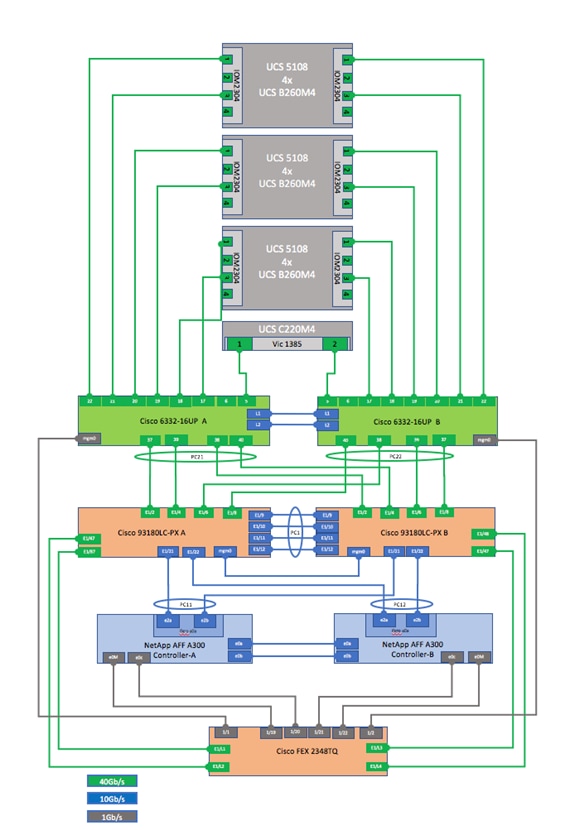
Table 5 through Table 12 provides the details of all the connections.
Table 5 Cisco Nexus 9000-A Cabling Information
| Local Device |
Local Port |
Connection |
Remote Device |
Remote Port |
| Cisco Nexus 9000 A
|
Eth1/1 |
40GbE |
Uplink to Customer Data Switch A |
|
| Eth1/2 |
40GbE |
Cisco UCS fabric interconnect A |
Eth 1/1 |
|
| Eth1/3 |
40GbE |
Uplink to Customer Data Switch B |
|
|
| Eth1/4 |
40GbE |
Cisco UCS fabric interconnect A |
Eth 1/3 |
|
| Eth1/5* |
40GbE |
Cisco Nexus 9000 Mgmt A |
Eth 1/3 |
|
| Eth1/6 |
40GbE |
Cisco UCS fabric interconnect B |
Eth 1/1 |
|
| Eth1/7* |
40GbE |
Cisco Nexus 9000 Mgmt B |
Eth 1/3 |
|
| Eth1/8 |
40GbE |
Cisco UCS fabric interconnect B |
Eth 1/3 |
|
| Eth1/9* |
40GbE |
Cisco Nexus 9000 B |
Eth1/9 |
|
| Eth1/10* |
40GbE |
Cisco Nexus 9000 B |
Eth1/10 |
|
| Eth1/11* |
40GbE |
Cisco Nexus 9000 B |
Eth1/11 |
|
| Eth1/12* |
40GbE |
Cisco Nexus 9000 B |
Eth1/12 |
|
| Eth1/15 |
40GbE |
NetApp controller 1 |
e0b |
|
| Eth1/16 |
40GbE |
NetApp controller 2 |
e0b |
|
| Eth1/17 |
40GbE |
NetApp controller 1 |
e0e |
|
| Eth1/18 |
40GbE |
NetApp controller 1 |
e0g |
|
| Eth1/19 |
40GbE |
NetApp controller 2 |
e0e |
|
| Eth1/20 |
40GbE |
NetApp controller 2 |
e0g |
|
| Eth1/29 |
40GbE |
Cisco UCS fabric interconnect A |
Eth1/9 |
|
| Eth1/30 |
40GbE |
Cisco UCS fabric interconnect B |
Eth1/9 |
|
| Eth1/31 |
40GbE |
Cisco UCS fabric interconnect A |
Eth1/13 |
|
| Eth1/32 |
40GbE |
Cisco UCS fabric interconnect B |
Eth1/13 |
|
| MGMT0 |
GbE |
Cisco Nexus 9000 Mgmt A |
Eth1/14 |
* The ports ETH1/9-12 can be replaced with E2/11 and E2/12 for 40G connectivity.
* The ports ETH1/5 and ETH1/7 can be replaced with E2/9 and E2/10 for 40G connectivity.
![]() For devices requiring GbE connectivity, use the GbE Copper SFP+s (GLC–T=).
For devices requiring GbE connectivity, use the GbE Copper SFP+s (GLC–T=).
Table 6 Cisco Nexus 9000-B Cabling Information
| Local Device |
Local Port |
Connection |
Remote Device |
Remote Port |
| Cisco Nexus 9000 B
|
Eth1/1 |
40GbE |
Uplink to Customer Data Switch A |
|
| Eth1/2 |
40GbE |
Cisco UCS fabric interconnect A |
Eth 1/5 |
|
| Eth1/3 |
40GbE |
Uplink to Customer Data Switch B |
|
|
| Eth1/4 |
40GbE |
Cisco UCS fabric interconnect A |
Eth 1/7 |
|
| Eth1/5* |
40GbE |
Cisco Nexus 9000 Mgmt A |
Eth 1/4 |
|
| Eth1/6 |
40GbE |
Cisco UCS fabric interconnect B |
Eth 1/5 |
|
| Eth1/7* |
40GbE |
Cisco Nexus 9000 Mgmt B |
Eth 1/4 |
|
| Eth1/8 |
40GbE |
Cisco UCS fabric interconnect B |
Eth 1/7 |
|
| Eth1/9* |
40GbE |
Cisco Nexus 9000 A |
Eth1/9 |
|
| Eth1/10* |
40GbE |
Cisco Nexus 9000 A |
Eth1/10 |
|
| Eth1/11* |
40GbE |
Cisco Nexus 9000 A |
Eth1/11 |
|
| Eth1/12* |
40GbE |
Cisco Nexus 9000 A |
Eth1/12 |
|
| Eth1/15 |
40GbE |
NetApp controller 1 |
e0d |
|
| Eth1/16 |
40GbE |
NetApp controller 2 |
e0d |
|
| Eth1/17 |
40GbE |
NetApp controller 1 |
e0f |
|
| Eth1/18 |
40GbE |
NetApp controller 1 |
e0h |
|
| Eth1/19 |
40GbE |
NetApp controller 2 |
e0f |
|
| Eth1/20 |
40GbE |
NetApp controller 2 |
e0h |
|
| Eth1/29 |
40GbE |
Cisco UCS fabric interconnect A |
Eth1/11 |
|
| Eth1/30 |
40GbE |
Cisco UCS fabric interconnect B |
Eth1/11 |
|
| Eth1/31 |
40GbE |
Cisco UCS fabric interconnect A |
Eth1/15 |
|
| Eth1/32 |
40GbE |
Cisco UCS fabric interconnect B |
Eth1/15 |
|
| MGMT0 |
GbE |
Cisco Nexus 9000 Mgmt B |
Eth1/14 |
* The ports ETH1/9-12 can be replaced with E2/11 and E2/12 for 40G connectivity.
* The ports ETH1/5 and ETH1/7 can be replaced with E2/9 and E2/10 for 40G connectivity.
![]() For devices requiring GbE connectivity, use the GbE Copper SFP+s (GLC–T=).
For devices requiring GbE connectivity, use the GbE Copper SFP+s (GLC–T=).
Table 7 NetApp Controller-1 Cabling Information
| Local Device |
Local Port |
Connection |
Remote Device |
Remote Port |
| NetApp controller 1 |
e0M |
GbE |
Cisco Nexus 9000 Mgmt A |
ETH1/18 |
| e0i |
GbE |
Cisco Nexus 9000 Mgmt A |
ETH1/19 |
|
| e0P |
GbE |
SAS shelves |
ACP port |
|
| e0a |
40GbE |
Cisco Nexus 5596 A |
Eth1/1 |
|
| e0b |
40GbE |
Cisco Nexus 9000 A |
Eth1/15 |
|
| e0c |
40GbE |
Cisco Nexus 5596 B |
Eth1/1 |
|
| e0d |
40GbE |
Cisco Nexus 9000 B |
Eth1/15 |
|
| e0e |
40GbE |
Cisco Nexus 9000 A |
Eth 1/17 |
|
| e0f |
40GbE |
Cisco Nexus 9000 B |
Eth 1/17 |
|
| e0g |
40GbE |
Cisco Nexus 9000 A |
Eth 1/18 |
|
| e0h |
40GbE |
Cisco Nexus 9000 B |
Eth 1/18 |
![]() When the term e0M is used, the physical Ethernet port to which the table is referring is the port indicated by a wrench icon on the rear of the chassis.
When the term e0M is used, the physical Ethernet port to which the table is referring is the port indicated by a wrench icon on the rear of the chassis.
Table 8 NetApp Controller-2 Cabling Information
| Local Port |
Connection |
Remote Device |
Remote Port |
|
| NetApp controller 2 |
e0M |
GbE |
Cisco Nexus 9000 Mgmt B |
ETH1/18 |
| e0i |
GbE |
Cisco Nexus 9000 Mgmt B |
ETH1/19 |
|
| e0P |
GbE |
SAS shelves |
ACP port |
|
| e0a |
40GbE |
Cisco Nexus 5596 A |
Eth1/2 |
|
| e0b |
40GbE |
Cisco Nexus 9000 A |
Eth1/16 |
|
| e0c |
40GbE |
Cisco Nexus 5596 B |
Eth1/2 |
|
| e0d |
40GbE |
Cisco Nexus 9000 B |
Eth1/16 |
|
| e0e |
40GbE |
Cisco Nexus 9000 A |
Eth 1/19 |
|
| e0f |
40GbE |
Cisco Nexus 9000 B |
Eth 1/19 |
|
| e0g |
40GbE |
Cisco Nexus 9000 A |
Eth 1/20 |
|
| e0h |
40GbE |
Cisco Nexus 9000 B |
Eth 1/20 |
![]() When the term e0M is used, the physical Ethernet port to which the table is referring is the port indicated by a wrench icon on the rear of the chassis.
When the term e0M is used, the physical Ethernet port to which the table is referring is the port indicated by a wrench icon on the rear of the chassis.
Table 9 Cisco Nexus 5596-A Cabling Information
| Local Device |
Local Port |
Connection |
Remote Device |
Remote Port |
| Cisco Nexus 5596 A
|
Eth1/1 |
40GbE |
NetApp controller 1 |
e0a |
| Eth1/2 |
40GbE |
NetApp controller 2 |
e0a |
|
| Eth1/41 |
40GbE |
Cisco Nexus 5596 B |
Eth1/41 |
|
| Eth1/42 |
40GbE |
Cisco Nexus 5596 B |
Eth1/42 |
|
| Eth1/43 |
40GbE |
Cisco Nexus 5596 B |
Eth1/43 |
|
| Eth1/44 |
40GbE |
Cisco Nexus 5596 B |
Eth1/44 |
|
| Eth1/45 |
40GbE |
Cisco Nexus 5596 B |
Eth1/45 |
|
| Eth1/46 |
40GbE |
Cisco Nexus 5596 B |
Eth1/46 |
|
| Eth1/47 |
40GbE |
Cisco Nexus 5596 B |
Eth1/47 |
|
| Eth1/48 |
40GbE |
Cisco Nexus 5596 B |
Eth1/48 |
|
| MGMT0 |
GbE |
Cisco Nexus 9000 Mgmt A |
ETH1/16 |
Table 10 Cisco Nexus 5596-B Cabling Information
| Local Device |
Local Port |
Connection |
Remote Device |
Remote Port |
| Cisco Nexus 5596 B
|
Eth1/1 |
40GbE |
NetApp controller 1 |
e0c |
| Eth1/2 |
40GbE |
NetApp controller 2 |
e0c |
|
| Eth1/41 |
40GbE |
Cisco Nexus 5596 A |
Eth1/41 |
|
| Eth1/42 |
40GbE |
Cisco Nexus 5596 A |
Eth1/42 |
|
| Eth1/43 |
40GbE |
Cisco Nexus 5596 A |
Eth1/43 |
|
| Eth1/44 |
40GbE |
Cisco Nexus 5596 A |
Eth1/44 |
|
| Eth1/45 |
40GbE |
Cisco Nexus 5596 A |
Eth1/45 |
|
| Eth1/46 |
40GbE |
Cisco Nexus 5596 A |
Eth1/46 |
|
| Eth1/47 |
40GbE |
Cisco Nexus 5596 A |
Eth1/47 |
|
| Eth1/48 |
40GbE |
Cisco Nexus 5596 A |
Eth1/48 |
|
| MGMT0 |
GbE |
Cisco Nexus 9000 Mgmt B |
ETH1/16 |
Table 11 Cisco UCS Fabric Interconnect A - Cabling Information
| Local Device |
Local Port |
Connection |
Remote Device |
Remote Port |
| Cisco UCS fabric interconnect A
|
Eth1/1 |
40GbE |
Cisco Nexus 9000 A |
Eth 1/2 |
| Eth1/2 |
40GbE |
Cisco UCS Chassis 1 Fabric Extender (FEX) A |
IOM 1/1 |
|
| Eth1/3 |
40GbE |
Cisco Nexus 9000 A |
Eth 1/4 |
|
| Eth1/4 |
40GbE |
Cisco UCS Chassis 1 Fabric Extender (FEX) A |
IOM 1/2 |
|
| Eth1/5 |
40GbE |
Cisco Nexus 9000 B |
Eth 1/2 |
|
| Eth1/6 |
40GbE |
Cisco UCS Chassis 1 Fabric Extender (FEX) A |
IOM 1/3 |
|
| Eth1/7 |
40GbE |
Cisco Nexus 9000 B |
Eth 1/4 |
|
| Eth1/8 |
40GbE |
Cisco UCS Chassis 1 Fabric Extender (FEX) A |
IOM 1/4 |
|
| Eth1/9 |
40GbE |
Cisco Nexus 9000 A |
Eth 1/29 |
|
| Eth1/10 |
40GbE |
Cisco UCS Chassis 2 Fabric Extender (FEX) A |
IOM 1/1 |
|
| Eth1/11 |
40GbE |
Cisco Nexus 9000 B |
Eth 1/29 |
|
| Eth1/12 |
40GbE |
Cisco UCS Chassis 2 Fabric Extender (FEX) A |
IOM 1/2 |
|
| Eth1/13 |
40GbE |
Cisco Nexus 9000 A |
Eth 1/31 |
|
| Eth1/14 |
40GbE |
Cisco UCS Chassis 2 Fabric Extender (FEX) A |
IOM 1/3 |
|
| Eth1/15 |
40GbE |
Cisco Nexus 9000 B |
Eth 1/31 |
|
| Eth1/16 |
40GbE |
Cisco UCS Chassis 2 Fabric Extender (FEX) A |
IOM 1/4 |
|
| Eth1/17 |
40GbE |
Cisco UCS C460-M4-1 |
PCI Slot 4 Port 0 |
|
| Eth1/18 |
40GbE |
Cisco UCS C460-M4-1 |
PCI Slot 9 Port 0 |
|
| Eth1/19 |
40GbE |
Cisco UCS C220-M4-1 |
VIC 1225 Port 0 |
|
| Eth1/20 |
40GbE |
Cisco UCS C240-M4-1 |
VIC 1225 Port 0 |
|
| MGMT0 |
GbE |
Cisco Nexus 9000 Mgmt A |
ETH1/15 |
|
| L1 |
GbE |
Cisco UCS fabric interconnect B |
L1 |
|
| L2 |
GbE |
Cisco UCS fabric interconnect B |
L2 |
Table 12 Cisco UCS Fabric Interconnect B - Cabling Information
| Local Device |
Local Port |
Connection |
Remote Device |
Remote Port |
| Cisco UCS fabric interconnect B
|
Eth1/1 |
40GbE |
Cisco Nexus 9000 A |
Eth 1/6 |
| Eth1/2 |
40GbE |
Cisco UCS Chassis 1 Fabric Extender (FEX) B |
IOM 1/1 |
|
| Eth1/3 |
40GbE |
Cisco Nexus 9000 A |
Eth 1/8 |
|
| Eth1/4 |
40GbE |
Cisco UCS Chassis 1 Fabric Extender (FEX) B |
IOM 1/2 |
|
| Eth1/5 |
40GbE |
Cisco Nexus 9000 B |
Eth 1/6 |
|
| Eth1/6 |
40GbE |
Cisco UCS Chassis 1 Fabric Extender (FEX) B |
IOM 1/3 |
|
| Eth1/7 |
40GbE |
Cisco Nexus 9000 B |
Eth 1/8 |
|
| Eth1/8 |
40GbE |
Cisco UCS Chassis 1 Fabric Extender (FEX) B |
IOM 1/4 |
|
| Eth1/9 |
40GbE |
Cisco Nexus 9000 A |
Eth 1/30 |
|
| Eth1/10 |
40GbE |
Cisco UCS Chassis 2 Fabric Extender (FEX) B |
IOM 1/1 |
|
| Eth1/11 |
40GbE |
Cisco Nexus 9000 B |
Eth 1/30 |
|
| Eth1/12 |
40GbE |
Cisco UCS Chassis 2 Fabric Extender (FEX) B |
IOM 1/2 |
|
| Eth1/13 |
40GbE |
Cisco Nexus 9000 A |
Eth 1/31 |
|
| Eth1/14 |
40GbE |
Cisco UCS Chassis 2 Fabric Extender (FEX) B |
IOM 1/3 |
|
| Eth1/15 |
40GbE |
Cisco Nexus 9000 B |
Eth 1/31 |
|
| Eth1/16 |
40GbE |
Cisco UCS Chassis 2 Fabric Extender (FEX) B |
IOM 1/4 |
|
| Eth1/17 |
40GbE |
Cisco UCS C460-M4-1 |
PCI Slot 4 Port 1 |
|
| Eth1/18 |
40GbE |
Cisco UCS C460-M4-1 |
PCI Slot 9 Port 1 |
|
| Eth1/19 |
40GbE |
Cisco UCS C220-M4-1 |
VIC 1225 Port 1 |
|
| Eth1/20 |
40GbE |
Cisco UCS C240-M4-1 |
VIC 1225 Port 1 |
|
| MGMT0 |
GbE |
Cisco Nexus 9000 Mgmt B |
ETH1/15 |
|
| L1 |
GbE |
Cisco UCS fabric interconnect A |
L1 |
|
| L2 |
GbE |
Cisco UCS fabric interconnect A |
L2 |
Management Pod Cabling
Table 13 through Table 16 provides the details of the connections used for Management Pod. As described earlier, in this reference design the Management Pod is directly connected to FlexPod as shown in Figure 9.
Table 13 Cisco Nexus 9000-A Management Pod Cabling Information
| Local Device |
Local Port |
Connection |
Remote Device |
Remote Port |
| Cisco Nexus 9000 Mgmt A
|
Eth1/1 |
40GbE |
Uplink to Customer Data Switch A |
|
| Eth1/2 |
40GbE |
Uplink to Customer Data Switch B |
|
|
| Eth1/3* |
40GbE |
Uplink to FlexPod Cisco Nexus 9000 A |
Eth1/5 |
|
| Eth1/4* |
40GbE |
Uplink to FlexPod Cisco Nexus 9000 B |
Eth1/5 |
|
| Eth1/5 |
40GbE |
Cisco UCS C-220-A |
Port 0 |
|
| Eth1/7 |
40GbE |
Cisco UCS C-220-B |
Port 0 |
|
| Eth1/9* |
40GbE |
Cisco Nexus 9000 Mgmt B |
Eth1/9 |
|
| Eth1/10* |
40GbE |
Cisco Nexus 9000 Mgmt B |
Eth1/10 |
|
| Eth1/11* |
40GbE |
Cisco Nexus 9000 Mgmt B |
Eth1/11 |
|
| Eth1/12* |
40GbE |
Cisco Nexus 9000 Mgmt B |
Eth1/12 |
|
| Eth1/14 |
1 GbE |
Cisco Nexus 9000 A |
Mgmt0 |
|
| Eth1/15 |
1 GbE |
Cisco UCS fabric interconnect A |
Mgmt0 |
|
| Eth1/16 |
1 GbE |
Cisco Nexus 5596 A |
Mgmt0 |
|
| Eth1/17 |
1 GbE |
Cisco UCS C-220-A |
CIMC M |
|
| Eth1/18 |
1 GbE |
NetApp controller 1 |
e0M |
|
| Eth1/19 |
1 GbE |
NetApp controller 1 |
e0i |
|
| MGMT0 |
GbE |
Customer GbE management switch |
Any |
* The ports ETH1/9-12 can be replaced with E2/11 and E2/12 for 40G connectivity.
* The ports ETH1/3-4 can be replaced with E2/9 and E2/10 for 40G connectivity.
Table 14 Cisco Nexus 9000-B Management Pod Cabling Information
| Local Device |
Local Port |
Connection |
Remote Device |
Remote Port |
| Cisco Nexus 9000 Mgmt B
|
Eth1/1 |
40GbE |
Uplink to Customer Data Switch A |
|
| Eth1/2 |
40GbE |
Uplink to Customer Data Switch B |
|
|
| Eth1/3* |
40GbE |
Uplink to FlexPod Cisco Nexus 9000 A |
Eth1/7 |
|
| Eth1/4* |
40GbE |
Uplink to FlexPod Cisco Nexus 9000 B |
Eth1/7 |
|
| Eth1/5 |
40GbE |
Cisco UCS C-220-A |
Port 1 |
|
| Eth1/7 |
40GbE |
Cisco UCS C-220-B |
Port 1 |
|
| Eth1/9* |
40GbE |
Cisco Nexus 9000 Mgmt A |
Eth1/9 |
|
| Eth1/10* |
40GbE |
Cisco Nexus 9000 Mgmt A |
Eth1/10 |
|
| Eth1/11* |
40GbE |
Cisco Nexus 9000 Mgmt A |
Eth1/11 |
|
| Eth1/12* |
40GbE |
Cisco Nexus 9000 Mgmt A |
Eth1/12 |
|
| Eth1/14 |
1 GbE |
Cisco Nexus 9000 B |
Mgmt0 |
|
| Eth1/15 |
1 GbE |
Cisco UCS fabric interconnect B |
Mgmt0 |
|
| Eth1/16 |
1 GbE |
Cisco Nexus 5596 B |
Mgmt0 |
|
| Eth1/17 |
1 GbE |
Cisco UCS C-220-B |
CIMC M |
|
| Eth1/18 |
1 GbE |
NetApp controller 2 |
e0M |
|
| Eth1/19 |
1 GbE |
NetApp controller 2 |
e0i |
|
| MGMT0 |
GbE |
Customer GbE management switch |
Any |
* The ports ETH1/9-12 can be replaced with E2/11 and E2/12 for 40G connectivity.
* The ports ETH1/3-4 can be replaced with E2/9 and E2/10 for 40G connectivity.
Table 15 Cisco UCS C-Series Server-A
| Local Device |
Local Port |
Connection |
Remote Device |
Remote Port |
| Cisco UCS C-220-A
|
CIMC Port M |
1GbE |
Cisco Nexus 9000 Management A |
Eth 1/17 |
| Port 0 |
40GbE |
Cisco Nexus 9000 Management A |
Eth 1/5 |
|
| Port 1 |
40GbE |
Cisco Nexus 9000 Management B |
Eth 1/5 |
Table 16 Cisco UCS C-Series Sever-B
| Local Device |
Local Port |
Connection |
Remote Device |
Remote Port |
| Cisco UCS C-220-B
|
CIMC Port M |
1GbE |
Cisco Nexus 9000 Management B |
Eth 1/17 |
| Port 0 |
40GbE |
Cisco Nexus 9000 Management A |
Eth 1/7 |
|
| Port 1 |
40GbE |
Cisco Nexus 9000 Management B |
Eth 1/7 |
Management Pod Installation
This section describes the configuration of the Management Pod to manage the multiple FlexPod environments for SAP HANA. In this reference architecture, the Management Pod includes a pair of Cisco Nexus 9000 Switches in standalone mode for out of band management network and a pair of Cisco UCS C220 M4 Rack-Mount Servers. The rack-mount servers for management are built on VMware ESXi. ESXi hosts will run PXE boot server, VMware vCenter and Windows Jump Host for Management. The next sections outline the configurations of each component in the Management Pod.
Network Configuration for Management Pod
The following section provides a detailed procedure for configuring the Cisco Nexus 9000 Series Switches for the Management Pod. It is based on cabling plan described in the Device Cabling section. If the systems connected on different ports, configure the switches accordingly following the guidelines described in this section.
![]() The configuration steps detailed in this section provides guidance for configuring the Cisco Nexus 9000 running release 6.1(2) within a multi-VDC environment.
The configuration steps detailed in this section provides guidance for configuring the Cisco Nexus 9000 running release 6.1(2) within a multi-VDC environment.
Dual-Homed FEX Topology (Active/Active FEX Topology)
The dual-homed FEX (Active/Active) topology is supported with NX-OS 7.0(3)I5(2) and later using Cisco Nexus 9300 and Nexus 9300-EX Series switches. The following topology shows that each FEX is dual-homed with two Cisco Nexus 9300 Series switches. The FEX-fabric interfaces for each FEX are configured as a vPC on both peer switches. The host interfaces on the FEX appear on both peer switches.
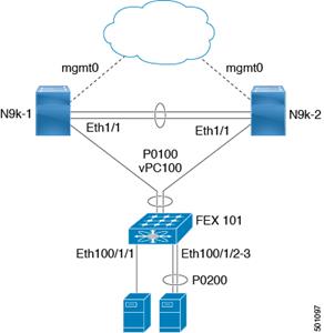
Cisco Nexus 9000 Series Switches─Network Initial Configuration Setup
This section provides the steps for the initial Cisco Nexus 9000 Series Switch setup.
Cisco Nexus 9000 A
To set up the initial configuration for the first Cisco Nexus switch, complete the following steps:
![]() On initial boot and connection to the serial or console port of the switch, the NX-OS setup should automatically start and attempt to enter Power on Auto Provisioning.
On initial boot and connection to the serial or console port of the switch, the NX-OS setup should automatically start and attempt to enter Power on Auto Provisioning.
---- Basic System Configuration Dialog VDC: 1 ----
This setup utility will guide you through the basic configuration of
the system. Setup configures only enough connectivity for management
of the system.
*Note: setup is mainly used for configuring the system initially,
when no configuration is present. So setup always assumes system
defaults and not the current system configuration values.
Press Enter at anytime to skip a dialog. Use ctrl-c at anytime
to skip the remaining dialogs.
Would you like to enter the basic configuration dialog (yes/no): yes
Do you want to enforce secure password standard (yes/no) [y]:
Create another login account (yes/no) [n]:
Configure read-only SNMP community string (yes/no) [n]:
Configure read-write SNMP community string (yes/no) [n]:
Enter the switch name : <<var_nexus_mgmt_A_hostname>>
Continue with Out-of-band (mgmt0) management configuration? (yes/no) [y]:
Mgmt0 IPv4 address : <<var_nexus_mgmt_A_mgmt0_ip>>
Mgmt0 IPv4 netmask : <<var_nexus_mgmt_A_mgmt0_netmask>>
Configure the default gateway? (yes/no) [y]:
IPv4 address of the default gateway : <<var_nexus_mgmt_A_mgmt0_gw>>
Configure advanced IP options? (yes/no) [n]:
Enable the telnet service? (yes/no) [n]:
Enable the ssh service? (yes/no) [y]:
Type of ssh key you would like to generate (dsa/rsa) [rsa]:
Number of rsa key bits <1024-2048> [2048]:
Configure the ntp server? (yes/no) [n]: y
NTP server IPv4 address : <<var_global_ntp_server_ip>>
Configure CoPP system profile (strict/moderate/lenient/dense/skip) [strict]:
The following configuration will be applied:
password strength-check
switchname <<var_nexus_mgmt_A_hostname>>
vrf context management
ip route 0.0.0.0/0 <<var_nexus_mgmt_A_mgmt0_gw>>
exit
no feature telnet
ssh key rsa 2048 force
feature ssh
ntp server <<var_global_ntp_server_ip>>
copp profile strict
interface mgmt0
ip address <<var_nexus_mgmt_A_mgmt0_ip>> <<var_nexus_mgmt_A_mgmt0_netmask>>
no shutdown
Would you like to edit the configuration? (yes/no) [n]: Enter
Use this configuration and save it? (yes/no) [y]: Enter
[########################################] 100%
Copy complete.
Cisco Nexus 9000 B
To set up the initial configuration for the second Cisco Nexus switch, complete the following steps:
![]() On initial boot and connection to the serial or console port of the switch, the NX-OS setup should automatically start and attempt to enter Power on Auto Provisioning.
On initial boot and connection to the serial or console port of the switch, the NX-OS setup should automatically start and attempt to enter Power on Auto Provisioning.
---- Basic System Configuration Dialog VDC: 1 ----
This setup utility will guide you through the basic configuration of
the system. Setup configures only enough connectivity for management
of the system.
*Note: setup is mainly used for configuring the system initially,
when no configuration is present. So setup always assumes system
defaults and not the current system configuration values.
Press Enter at anytime to skip a dialog. Use ctrl-c at anytime
to skip the remaining dialogs.
Would you like to enter the basic configuration dialog (yes/no): yes
Create another login account (yes/no) [n]:
Configure read-only SNMP community string (yes/no) [n]:
Configure read-write SNMP community string (yes/no) [n]:
Enter the switch name : <<var_nexus_mgmt_B_hostname>>
Continue with Out-of-band (mgmt0) management configuration? (yes/no) [y]:
Mgmt0 IPv4 address : <<var_nexus_mgmt_B_mgmt0_ip>>
Mgmt0 IPv4 netmask : <<var_nexus_mgmt_B_mgmt0_netmask>>
Configure the default gateway? (yes/no) [y]:
IPv4 address of the default gateway : <<var_nexus_mgmt_B_mgmt0_gw>>
Configure advanced IP options? (yes/no) [n]:
Enable the telnet service? (yes/no) [n]:
Enable the ssh service? (yes/no) [y]:
Type of ssh key you would like to generate (dsa/rsa) [rsa]:
Number of rsa key bits <1024-2048> [2048]:
Configure the ntp server? (yes/no) [n]: y
NTP server IPv4 address : <<var_global_ntp_server_ip>>
Configure default interface layer (L3/L2) [L3]: L2
Configure default switchport interface state (shut/noshut) [shut]: Enter
Configure CoPP system profile (strict/moderate/lenient/dense/skip) [strict]:
The following configuration will be applied:
password strength-check
switchname <<var_nexus_mgmt_B_hostname>>
vrf context management
ip route 0.0.0.0/0 <<var_nexus_mgmt_B_mgmt0_gw>>
exit
no feature telnet
ssh key rsa 2048 force
feature ssh
ntp server <<var_global_ntp_server_ip>>
copp profile strict
interface mgmt0
ip address <<var_nexus_mgmt_B_mgmt0_ip>> <<var_nexus_mgmt_B_mgmt0_netmask>>
no shutdown
Would you like to edit the configuration? (yes/no) [n]: Enter
Use this configuration and save it? (yes/no) [y]: Enter
[########################################] 100%
Copy complete.
Enable Appropriate Cisco Nexus 9000 Series Switches - Features and Settings
Cisco Nexus 9000 A and Cisco Nexus 9000 B
To enable the IP switching feature and set default spanning tree behaviors, complete the following steps:
1. On each Nexus 9000, enter configuration mode:
config terminal
2. Use the following commands to enable the necessary features:
feature udld
feature lacp
feature vpc
feature interface-vlan
feature lldp
3. Configure spanning tree defaults:
spanning-tree port type network default
spanning-tree port type edge bpduguard default
spanning-tree port type edge bpdufilter default
4. Save the running configuration to start-up:
copy run start
Create VLANs for Management Traffic
Cisco Nexus 9000 A and Cisco Nexus 9000 B
To create the necessary virtual local area networks (VLANs), complete the following step on both switches:
1. From the configuration mode, run the following commands:
vlan <<var_oob_vlan_id>>
name OOB-Mgmt
vlan <<var_admin_vlan_id>>
name HANA-Admin
vlan <<var_boot_vlan_id>>
name HANA-Boot
Create VLANs for ESXi Traffic
Cisco Nexus 9000 A and Cisco Nexus 9000 B
To create the necessary virtual local area networks (VLANs), complete the following step on both switches:
1. From the configuration mode, run the following commands:
vlan <<var_esx_mgmt_vlan_id>>
name ESX-MGMT
vlan <<var_esx_vmotion_vlan_id>>
name ESX-vMotion
vlan <<var_esx_nfs_vlan_id>>
name ESX-NFS
Configure Virtual Port Channel Domain
Cisco Nexus 9000 A
To configure virtual port channels (vPCs) for switch A, complete the following steps:
1. From the global configuration mode, create a new vPC domain:
vpc domain <<var_nexus_vpc_domain_mgmt_id>>
2. Make Nexus 9000A the primary vPC peer by defining a low priority value:
role priority 10
3. Use the management interfaces on the supervisors of the Nexus 9000s to establish a keepalive link:
peer-keepalive destination <<var_nexus_mgmt_B_mgmt0_ip>> source <<var_nexus_mgmt_A_mgmt0_ip>>
4. Enable following features for this vPC domain:
peer-switch
delay restore 150
peer-gateway
auto-recovery
Cisco Nexus 9000 B
To configure vPCs for switch B, complete the following steps:
1. From the global configuration mode, create a new vPC domain:
vpc domain <<var_nexus_vpc_domain_mgmt_id>>
2. Make Cisco Nexus 9000 B the secondary vPC peer by defining a higher priority value than that of the Nexus 9000 A:
role priority 20
3. Use the management interfaces on the supervisors of the Cisco Nexus 9000s to establish a keepalive link:
peer-keepalive destination <<var_nexus_mgmt_A_mgmt0_ip>> source <<var_nexus_mgmt_B_mgmt0_ip>>
4. Enable following features for this vPC domain:
peer-switch
delay restore 150
peer-gateway
auto-recovery
Configure Network Interfaces for the VPC Peer Links
Cisco Nexus 9000 A
1. Define a port description for the interfaces connecting to VPC Peer <<var_nexus_mgmt_B_hostname>>.
interface Eth1/9
description VPC Peer <<var_nexus_mgmt_B_hostname>>:1/9
interface Eth1/10
description VPC Peer <<var_nexus_mgmt_B_hostname>>:1/10
interface Eth1/11
description VPC Peer <<var_nexus_mgmt_B_hostname>>:1/11
interface Eth1/12
description VPC Peer <<var_nexus_mgmt_B_hostname>>:1/12
2. Apply a port channel to both VPC Peer links and bring up the interfaces.
interface Eth1/9-12
channel-group 1 mode active
no shutdown
3. Define a description for the port-channel connecting to <<var_nexus_mgmt_B_hostname>>.
interface Po1
description vPC peer-link
4. Make the port-channel a switchport, and configure a trunk to allow Management VLANs.
switchport
switchport mode trunk
switchport trunk allowed vlan <<var_admin_vlan_id>>,<<var_boot_vlan_id>>,<<var_oob_vlan_id>>,<<var_esx_mgmt_vlan_id>>,<<var_esx_vmotion_vlan_id>>,<<var_esx_nfs_vlan_id>>
5. Make this port-channel the VPC peer link and bring it up.
spanning-tree port type network
vpc peer-link
no shutdown
Cisco Nexus 9000 B
1. Define a port description for the interfaces connecting to VPC peer <<var_nexus_A_hostname>>.
interface Eth1/9
description VPC Peer <<var_nexus_mgmt_A_hostname>>:1/9
interface Eth1/10
description VPC Peer <<var_nexus_mgmt_A_hostname>>:1/10
interface Eth1/11
description VPC Peer <<var_nexus_mgmt_A_hostname>>:1/11
interface Eth1/12
description VPC Peer <<var_nexus_mgmt_A_hostname>>:1/12
2. Apply a port channel to both VPC peer links and bring up the interfaces.
interface Eth1/9-12
channel-group 1 mode active
no shutdown
3. Define a description for the port-channel connecting to <<var_nexus_A_hostname>>.
interface Po1
description vPC peer-link
4. Make the port-channel a switchport, and configure a trunk to allow Management VLANs.
switchport
switchport mode trunk
switchport trunk allowed vlan <<var_admin_vlan_id>>,<<var_boot_vlan_id>>,<<var_oob_vlan_id>>,<<var_esx_mgmt_vlan_id>>,<<var_esx_vmotion_vlan_id>>,<<var_esx_nfs_vlan_id>>
5. Make this port-channel the VPC peer link and bring it up.
spanning-tree port type network
vpc peer-link
no shutdown
6. Save the running configuration to start-up in both Nexus 9000s.
copy run start
Configure Network Interfaces to Cisco UCS C220 Management Server
Cisco Nexus 9000 A
1. Define a port description for the interface connecting to <<var_c220>>-A and <<var_c220>>-B
interface Eth1/5
description << var_C220>>-A:P1
interface Eth1/7
description << var_C220>>-B:P1
2. Make the a switchport, and configure a trunk to allow NFS, PXE, Management, VM traffic VLANs
interface Eth1/5
switchport
switchport mode trunk
switchport trunk allowed vlan <<var_admin_vlan_id>>,<<var_boot_vlan_id>>,<<var_oob_vlan_id>>,<<var_esx_mgmt>>
interface Eth1/7
switchport
switchport mode trunk
switchport trunk allowed vlan <<var_admin_vlan_id>>,<<var_boot_vlan_id>>,<<var_oob_vlan_id>>,<<var_esx_mgmt>>
Cisco Nexus 9000 B
1. Define a port description for the interface connecting to <<var_c220>>-A and <<var_c220>>-B
interface Eth1/5
description << var_C220>>-A:P2
interface Eth1/7
description << var_C220>>-B:P2
2. Make the a switchport, and configure a trunk to allow NFS, PXE, Management, VM traffic VLANs
interface Eth1/5
switchport
switchport mode trunk
switchport trunk allowed vlan <<var_admin_vlan_id>>,<<var_boot_vlan_id>>,<<var_oob_vlan_id>>,<<var_esx_mgmt>>
interface Eth1/7
switchport
switchport mode trunk
switchport trunk allowed vlan <<var_admin_vlan_id>>,<<var_boot_vlan_id>>,<<var_oob_vlan_id>>,<<var_esx_mgmt>>
Configure Network Interfaces for Out of Band Management Plane Access
This section provides an example of the configuration for the Management Ports. The cabling and configuration is based on the datacenter requirement. Since most the Management Ports are 1-GbE, use 1-GbE SFPs to connect Twisted Pair Ethernet Cable.
Cisco Nexus 9000 A
To enable management access across the IP switching environment, complete the following steps:
1. Define a port description for the interface connecting to the management switch:
interface 1/14
description OOB-Mgmt-FlexPod-NX9396-A
interface 1/15
description OOB-Mgmt-UCS-FI-A
interface 1/16
description OOB-Mgmt-NX5596-A
interface 1/17
description OOB-Mgmt-C220-CIMC-A
interface 1/18
description OOB-Mgmt-NetApp-8000-A-e0M
interface 1/19
description OOB-Mgmt-NetApp-8000-A-e0i
2. Configure the port as an access VLAN carrying the Out of Band management VLAN traffic.
interface 1/14-19
switchport
switchport mode access
switchport access vlan <<var_oob_vlan_id>>
speed 1000
no shutdown
3. Save the running configuration to start-up.
copy run start
Cisco Nexus 9000 B
1. Define a port description for the interface connecting to the management switch:
interface 1/14
description OOB-Mgmt-FlexPod-NX9396-B
interface 1/15
description OOB-Mgmt-UCS-FI-B
interface 1/16
description OOB-Mgmt-NX5596-B
interface 1/17
description OOB-Mgmt-C220-CIMC-B
interface 1/18
description OOB-Mgmt-NetApp-8000-B-e0M
interface 1/19
description OOB-Mgmt-NetApp-8000-B-e0i
2. Configure the port as an access VLAN carrying the Out of Band management VLAN traffic.
interface 1/14-19
switchport
switchport mode access
switchport access vlan <<var_oob_vlan_id>>
speed 1000
no shutdown
3. Save the running configuration to start-up.
copy run start
Direct Connection of Management Pod to FlexPod Infrastructure
This section describes the configuration steps for Cisco Nexus 9000 switches in the Management Pod connected to each FlexPod instance.
Cisco Nexus 9000 A
1. Define a port description for the interface connecting to <<var_nexus_A_hostname>>.
interface Eth1/3
description <<var_nexus_A_hostname>>:1/5
2. Apply it to a port channel and bring up the interface.
interface eth1/3
channel-group 6 mode active
no shutdown
3. Define a port description for the interface connecting to <<var_nexus_B_hostname>>.
interface Eth1/4
description <<var_nexus_B_hostname>>:1/5
4. Apply it to a port channel and bring up the interface.
interface Eth1/4
channel-group 6 mode active
no shutdown
5. Define a description for the port-channel connecting to FlexPod Switch.
interface Po6
description <<var_nexus_A_hostname>>
6. Make the port-channel a switchport, and configure a trunk to allow all Management VLANs.
switchport
switchport mode trunk
switchport trunk allowed vlan <<var_admin_vlan_id>>,<<var_boot_vlan_id>>,<<var_oob_vlan_id>>,<<var_esx_mgmt>>,<<var_vhana_esx_mgmt_vlan_id>>
7. Make the port channel and associated interfaces spanning tree network ports.
spanning-tree port type network
8. Set the MTU to be 9216 to support jumbo frames.
mtu 9216
9. Make this a VPC port-channel and bring it up.
vpc 6
no shutdown
10. Save the running configuration to start-up.
copy run start
Cisco Nexus 9000 B
1. Define a port description for the interface connecting to <<var_nexus_A_hostname>>.
interface Eth1/3
description <<var_nexus_A_hostname>>:1/7
2. Apply it to a port channel and bring up the interface.
interface eth1/3
channel-group 6 mode active
no shutdown
3. Define a port description for the interface connecting to <<var_nexus_B_hostname>>.
interface Eth1/4
description <<var_nexus_B_hostname>>:1/7
4. Apply it to a port channel and bring up the interface.
interface Eth1/4
channel-group 6 mode active
no shutdown
5. Define a description for the port-channel connecting to FlexPod Switch.
interface Po6
description <<var_nexus_A_hostname>>
6. Make the port-channel a switchport, and configure a trunk to allow all Management VLANs
switchport
switchport mode trunk
switchport trunk allowed vlan <<var_admin_vlan_id>>,<<var_boot_vlan_id>>,<<var_oob_vlan_id>>,<<var_esx_mgmt>>,<<var_vhana_esx_mgmt_vlan_id>>
7. Make the port channel and associated interfaces spanning tree network ports.
spanning-tree port type network
8. Set the MTU to be 9216 to support jumbo frames.
mtu 9216
9. Make this a VPC port-channel and bring it up.
vpc 6
no shutdown
10. Save the running configuration to start-up.
copy run start
Uplink into Existing Network Infrastructure
Depending on the available network infrastructure, several methods and features can be used to uplink from the Management environment to connect to FlexPod SAP HANA environment. If an existing Cisco Nexus environment is present, Cisco recommends using vPCs to uplink the Cisco Nexus 9000 switches in the Management environment to the FlexPod SAP HANA environment. The previously described procedures can be used to create an uplink vPC to the existing environment. Make sure to run copy run start to save the configuration on each switch after the configuration is completed.
Management Server Installation
The Cisco UCS C220 Server will act as a management server for the Solution. It requires VMware ESXi 6.5a both the Cisco UCS C220 Servers and for PXE boot tasks, it needs SLES11SP3 64Bit configuration. Windows system can also be considered (optional) on this management servers.
Server Configuration
The Cisco UCS C220 M4 Rack-Mount Servers are used to manage the FlexPod environment.
Cisco Integrated Management Controller (CIMC) of Cisco UCS C220 M4 Servers and both the Cisco UCS VIC 1325 card ports must be connected to Cisco Nexus 9000 Series Switches in the management network, as defined in the Cabling Section. Three IP addresses are necessary for each Cisco UCS C220 M4 Server - one each for the CIMC, ESXi console and PXE boot VM.
CIMC Configuration
To configure the IP-Address on the CIMC complete the following steps:
1. With a direct attached monitor and keyboard press F8 when the following screen appears:
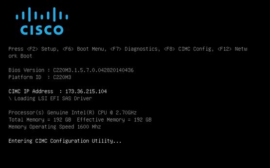
2. Configure the CIMC as required to be accessible from the Management LAN.
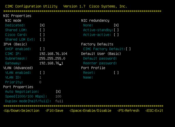
3. When connecting the CIMC to Management Switch, complete the following steps:
a. Choose Dedicated under NIC mode
b. Enter the IP address for CIMC which is accessible from the Management Network
c. Enter the Subnet mask for CIMC network
d. Enter the Default Gateway for CIMC network
e. Choose NIC redundancy as None
f. Enter the Default password for admin user under Default User (Basic) and Reenter password
Storage Configuration
To create a redundant virtual drive (RAID 1) on the internal disks to host ESXi and VMs, complete the following steps:
![]() Virtual Drive on RAID can be created from BIOS.
Virtual Drive on RAID can be created from BIOS.
1. On your browser go to IP address Set for CIMC.
2. In the Navigation Pane Server > Summary.
3. Click on Launch KVM Console.
4. Open with Java JRE installed.
5. Press Ctrl H to Launch WebBIOS.
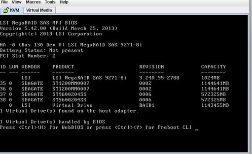
6. Click Start to Configure the RAID.
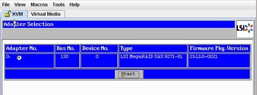
7. Click the Configuration Wizard.
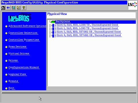
8. Click New Configuration.
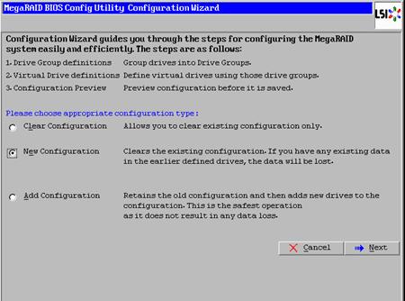
9. Click Yes to Clear the configuration.
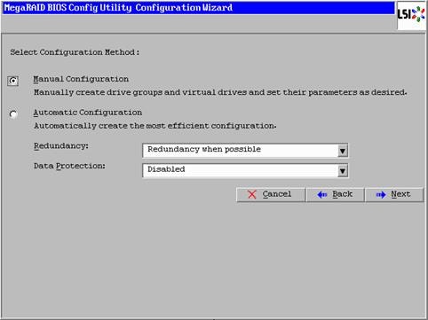
10. Choose the Disks and click Add To Array.
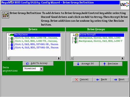
11. Click on Accept DG.
12. Click Next.
13. Choose Drive Group and Click on Add to SPAN.
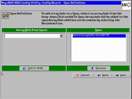
14. Click Next on the Span Definition screen.
15. Make sure that RAID Level RAID 1 is selected.
16. Click Accept.
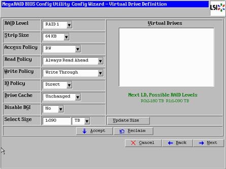
17. Click Yes to Accept Write through Mode.
18. Click Next to Create Virtual Drive.
19. Click Accept to Save the Configuration.
20. Click Yes to Initialize the Virtual Drive.
21. Click Home and Exist the RAID Configuration.
22. Reboot the server From CIMC web browser Server > Summary > Hard Reset Server
![]() Alternately, RAID1 for two internal disks in the Management server can be set up from the CIMC web Browser by completing the following steps:
Alternately, RAID1 for two internal disks in the Management server can be set up from the CIMC web Browser by completing the following steps:
23. Open a web browser and navigate to the Cisco C220-M4 CIMC IP address.
24. Enter admin as the user name and enter the administrative password, which was previously set.
25. Click Login to log in to CIMC.
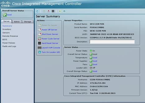
26. On the Control Pane click the Storage tab.
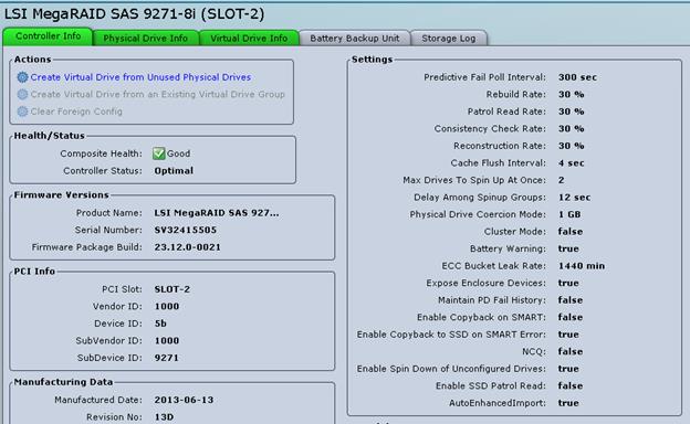
27. Click Create Virtual Drive from Unused Physical Drives.
28. Choose RAID Level 1 and Select the Disks and Click on >> to add them in the Drive Groups.
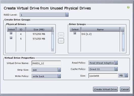
29. Click Create Virtual Drive to create the virtual drive.
30. Click the Virtual Drive Info.
31. Click Initialize.
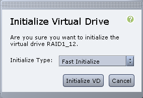
32. Click Initialize VD.
Cisco UCS VIC1325 vNIC Configuration
To configure Cisco UCS VIC 1325 vNIC through the CIMC browser, complete the following steps:
1. Click Inventory under the Server tab.
2. Click the Cisco VIC Adapters.
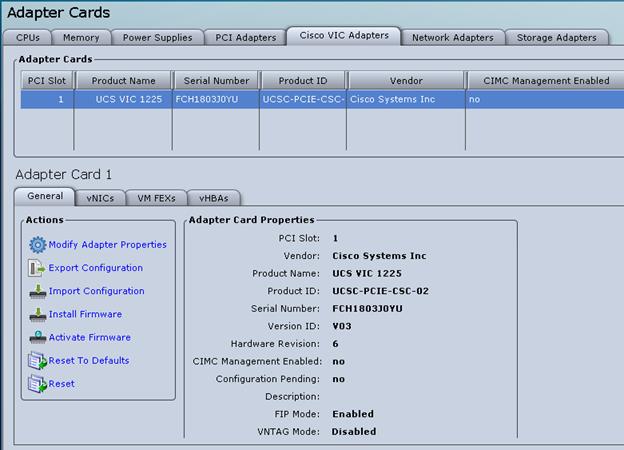
3. Click vNICs.
4. Under eth0 click Properties to change the MTU to 9000.
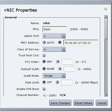
5. Under eth1 click Properties to change the MTU to 9000.
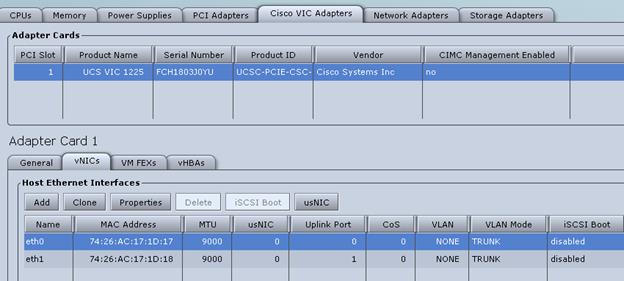
6. Reboot the server From Server --> Summary à Hard Reset Server.
VMware ESXi Installation
Install VMware ESXi 6.5a on the Cisco UCS M4 C-Series server and configure both Cisco UCS VIC 1325 interfaces as the ESX Management Network by completing the following steps.
Download Cisco Custom Image for ESXi 6.5a
1. Click the following link vmware login page.
2. Type your email or customer number and the password and then click Log in.
3. Click the following link Cisco ESXi 6.5a Download.
4. Click Download.
5. Save it to your destination folder.
VMware ESXi Hosts ESXi-Mgmt-01 and ESXi-Mgmt-02
To prepare the server for the OS installation, complete the following steps on each ESXi host:
1. On your Browser go to IP address Set for CIMC.
2. In the Navigation Pane Server > Summary.
3. Click Launch KVM Console.
4. Open with Java JRE installed.
5. Click the VM tab.
6. Click Add Image.
7. Browse to the ESXi installer ISO image file and click Open.
8. Download VMware-VMvisor-Installer-201701001-4887370.x86_64.iso.
9. Select the Mapped checkbox to map the newly added image.
10. Click the KVM tab to monitor the server boot.
11. Boot the server by selecting Boot Server and click OK. Then click OK again.
Install ESXi
Management Server ESXi-Mgmt-01 and ESXi-Mgmt-02
To install VMware ESXi on the local disk, complete the following steps on each host:
1. On reboot, the machine detects the presence of the ESXi installation media. Select the ESXi installer from the menu that is displayed.
2. After the installer is finished loading, press Enter to continue with the installation.
3. Read and accept the end-user license agreement (EULA). Press F11 to accept and continue.
4. Select the local disk which was previously created for ESXi and press Enter to continue with the installation.
5. Select the appropriate keyboard layout and press Enter.
6. Enter and confirm the root password and press Enter.
7. The installer issues a warning that existing partitions will be removed from the volume. Press F11 to continue with the installation.
8. After the installation is complete, clear the Mapped checkbox (located in the Virtual Media tab of the KVM console) to unmap the ESXi installation image.
9. The ESXi installation image must be unmapped to make sure that the server reboots into ESXi and not into the installer.
10. The Virtual Media window might issue a warning stating that it is preferable to eject the media from the guest. Click Yes to unmap the image.
11. From the KVM tab, press Enter to reboot the server.
Set Up Management Networking for ESXi Hosts
Adding a management network for each VMware host is necessary for managing the host. To add a management network for the VMware hosts, complete the following steps on each ESXi host:
VMware ESXi Host ESXi-Mgmt-01
To configure the ESXi-Mgmt-01 ESXi host with access to the management network, complete the following steps:
1. After the server has finished rebooting, press F2 to customize the system.
2. Log in as root and enter the corresponding password.
3. Select the Configure the Management Network option and press Enter.
4. Select the VLAN (Optional) option and press Enter.
5. Enter the <<var_oob_vlan_id>> and press Enter.
6. From the Configure Management Network menu, select IP Configuration and press Enter.
7. Select the Set Static IP Address and Network Configuration option by using the space bar.
8. Enter the IP address for managing the first ESXi host: <<var_vm_host_mgmt_01_ip>>.
9. Enter the subnet mask for the first ESXi host.
10. Enter the default gateway for the first ESXi host.
11. Press Enter to accept the changes to the IP configuration.
12. Select the IPv6 Configuration option and press Enter.
13. Using the spacebar, unselect Enable IPv6 (restart required) and press Enter.
14. Select the DNS Configuration option and press Enter.
15. Because the IP address is assigned manually, the DNS information must also be entered manually.
16. Enter the IP address of the primary DNS server.
17. Optional: Enter the IP address of the secondary DNS server.
18. Enter the fully qualified domain name (FQDN) for the first ESXi host.
19. Press Enter to accept the changes to the DNS configuration.
20. Press Esc to exit the Configure Management Network submenu.
21. Press Y to confirm the changes and return to the main menu.
22. The ESXi host reboots. After reboot, press F2 and log back in as root.
23. Select Test Management Network to verify that the management network is set up correctly and press Enter.
24. Press Enter to run the test.
25. Press Enter to exit the window.
26. Press Esc to log out of the VMware console.
VMware ESXi Host ESXi-Mgmt-02
To configure the ESXi-Mgmt-02 ESXi host with access to the management network, complete the following steps:
1. After the server has finished rebooting, press F2 to customize the system.
2. Log in as root and enter the corresponding password.
3. Select the Configure the Management Network option and press Enter.
4. Select the VLAN (Optional) option and press Enter.
5. Enter the <<var_oob_vlan_id>> and press Enter.
6. From the Configure Management Network menu, select IP Configuration and press Enter.
7. Select the Set Static IP Address and Network Configuration option by using the space bar.
8. Enter the IP address for managing the second ESXi host: <<var_vm_host_mgmt_02_ip>>.
9. Enter the subnet mask for the second ESXi host.
10. Enter the default gateway for the second ESXi host.
11. Press Enter to accept the changes to the IP configuration.
12. Select the IPv6 Configuration option and press Enter.
13. Using the spacebar, unselect Enable IPv6 (restart required) and press Enter.
14. Select the DNS Configuration option and press Enter.
![]() Since the IP address is assigned manually, the DNS information must also be entered manually.
Since the IP address is assigned manually, the DNS information must also be entered manually.
15. Enter the IP address of the primary DNS server.
16. Optional: Enter the IP address of the secondary DNS server.
17. Enter the FQDN for the second ESXi host.
18. Press Enter to accept the changes to the DNS configuration.
19. Press Esc to exit the Configure Management Network submenu.
20. Press Y to confirm the changes and return to the main menu.
21. The ESXi host reboots. After reboot, press F2 and log back in as root.
22. Select Test Management Network to verify that the management network is set up correctly and press Enter.
23. Press Enter to run the test.
24. Press Enter to exit the window.
25. Press Esc to log out of the VMware console.
Set Up VMkernel Ports and Virtual Switch
VMware ESXi Host ESXi-Mgmt-01
![]() Repeat the steps in this section for all the ESXi Hosts.
Repeat the steps in this section for all the ESXi Hosts.
To set up the VMkernel ports and the virtual switches on the ESXi-Mgmt-01 ESXi host, complete the following steps:
1. From each Web client, select the host in the inventory.
2. Click the Networking in the main pane.
3. Click virtual switches on the folder tap.
4. Select the Add standard virtual switch configuration and click Edit.
5. Specify the Name - FlexPod, MTU - 9000 and up-link 1 (select the first enic interface) and cllick OK to finalize the setup for VM Network.
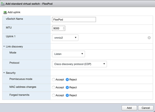
6. On the left, click Add Uplink.
7. Add vmnick3 to the vSwitch and click Save.
8. Configure additional port groups on this new vSwitch.
9. Select Networking in the main pane.
10. Select Port groups in the Navigation tab.
11. Select Add port group.
12. For Network Label enter HANA-Boot.
13. Enter VLAN ID for PXE Boot.
14. Click Finish. The is created.
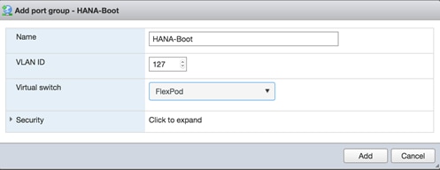
15. Add additional port groups for the Management network as well to the vSwitch.
16. Repeat the last section for the Mgmt network.
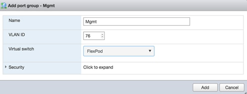
17. Click Finish
Mount Required Datastores
For VMware ESXi Hosts ESXi-Mgmt-01 and ESXi-Mgmt-02, it is recommended to use Additional NetApp Storage for Management Pod for redundancy and failure scenarios. If you have NetApp storage for Management, then create a volume for datastores, create a VM Kernel port for storage, assign IP address and complete the following steps on each of the ESXi hosts:
1. From each vSphere Client, select the host in the inventory.
2. Click the Configuration tab to enable configurations.
3. Click Storage in the Hardware pane.
4. From the Datastore area, click Add Storage to open the Add Storage wizard.
5. Select Network File System and click Next.
6. The wizard prompts for the location of the NFS export. Enter the IP address for NFS Storage Device
7. Enter Volume path for the NFS export.
8. Make sure that the Mount NFS read only checkbox is NOT selected.
9. Enter mgmt_datastore_01 as the datastore name.
10. Click Next to continue with the NFS datastore creation.
11. Click Finish to finalize the creation of the NFS datastore.
Configure NTP on ESXi Hosts
VMware ESXi Hosts ESXi-Mgmt-01 and ESXi-Mgmt-02
To configure Network Time Protocol (NTP) on the ESXi hosts, complete the following steps on each host:
1. From each vSphere Client, select the host in the inventory.
2. Click the Configuration tab to enable configurations.
3. Click Time Configuration in the Software pane.
4. Click Properties at the upper right side of the window.
5. At the bottom of the Time Configuration dialog box, click Options.
6. In the NTP Daemon Options dialog box, complete the following steps:
a. Click General in the left pane, select Start and stop with host.
b. Click NTP Settings in the left pane and click Add.
7. In the Add NTP Server dialog box, enter <<var_global_ntp_server_ip>> as the IP address of the NTP server and click OK.
8. In the NTP Daemon Options dialog box, select the Restart NTP Service to Apply Changes checkbox and click OK.
9. In the Time Configuration dialog box, complete the following steps:
a. Select the NTP Client Enabled checkbox and click OK.
b. Verify that the clock is now set to approximately the correct time.
10. The NTP server time may vary slightly from the host time.
FlexPod Network Configuration for SAP HANA
This section provides a detailed procedure for configuring the Cisco Nexus 9000 Switches for SAP HANA environment. The switch configuration in this section based on cabling plan described in the Device Cabling section. If the systems connected on different ports, configure the switches accordingly following the guidelines described in this section.
![]() The configuration steps detailed in this section provides guidance for configuring the Cisco Nexus 9000 running release 6.1(2) within a multi-VDC environment.
The configuration steps detailed in this section provides guidance for configuring the Cisco Nexus 9000 running release 6.1(2) within a multi-VDC environment.
Cisco Nexus 9000 Series Switch ─ Network Initial Configuration Setup
The following steps provide details for the initial Cisco Nexus 9000 Series Switch setup.
Cisco Nexus A
To set up the initial configuration for the first Cisco Nexus switch complete the following steps:
![]() On initial boot and connection to the serial or console port of the switch, the NX-OS setup should automatically start and attempt to enter Power on Auto Provisioning.
On initial boot and connection to the serial or console port of the switch, the NX-OS setup should automatically start and attempt to enter Power on Auto Provisioning.
---- Basic System Configuration Dialog VDC: 1 ----
This setup utility will guide you through the basic configuration of
the system. Setup configures only enough connectivity for management
of the system.
*Note: setup is mainly used for configuring the system initially,
when no configuration is present. So setup always assumes system
defaults and not the current system configuration values.
Press Enter at anytime to skip a dialog. Use ctrl-c at anytime
to skip the remaining dialogs.
Would you like to enter the basic configuration dialog (yes/no): yes
Do you want to enforce secure password standard (yes/no) [y]:
Create another login account (yes/no) [n]:
Configure read-only SNMP community string (yes/no) [n]:
Configure read-write SNMP community string (yes/no) [n]:
Enter the switch name : <<var_nexus_A_hostname>>
Continue with Out-of-band (mgmt0) management configuration? (yes/no) [y]:
Mgmt0 IPv4 address : <<var_nexus_A_mgmt0_ip>>
Mgmt0 IPv4 netmask : <<var_nexus_A_mgmt0_netmask>>
Configure the default gateway? (yes/no) [y]:
IPv4 address of the default gateway : <<var_nexus_A_mgmt0_gw>>
Configure advanced IP options? (yes/no) [n]:
Enable the telnet service? (yes/no) [n]:
Enable the ssh service? (yes/no) [y]:
Type of ssh key you would like to generate (dsa/rsa) [rsa]:
Number of rsa key bits <1024-2048> [2048]:
Configure the ntp server? (yes/no) [n]: y
NTP server IPv4 address : <<var_global_ntp_server_ip>>
Configure CoPP system profile (strict/moderate/lenient/dense/skip) [strict]:
The following configuration will be applied:
password strength-check
switchname <<var_nexus_A_hostname>>
vrf context management
ip route 0.0.0.0/0 <<var_nexus_A_mgmt0_gw>>
exit
no feature telnet
ssh key rsa 2048 force
feature ssh
ntp server <<var_global_ntp_server_ip>>
copp profile strict
interface mgmt0
ip address <<var_nexus_A_mgmt0_ip>> <<var_nexus_A_mgmt0_netmask>>
no shutdown
Would you like to edit the configuration? (yes/no) [n]: Enter
Use this configuration and save it? (yes/no) [y]: Enter
[########################################] 100%
Copy complete.
Cisco Nexus B
To set up the initial configuration for the second Cisco Nexus switch complete the following steps:
![]() On initial boot and connection to the serial or console port of the switch, the NX-OS setup should automatically start and attempt to enter Power on Auto Provisioning.
On initial boot and connection to the serial or console port of the switch, the NX-OS setup should automatically start and attempt to enter Power on Auto Provisioning.
---- Basic System Configuration Dialog VDC: 1 ----
This setup utility will guide you through the basic configuration of
the system. Setup configures only enough connectivity for management
of the system.
*Note: setup is mainly used for configuring the system initially,
when no configuration is present. So setup always assumes system
defaults and not the current system configuration values.
Press Enter at anytime to skip a dialog. Use ctrl-c at anytime
to skip the remaining dialogs.
Would you like to enter the basic configuration dialog (yes/no): yes
Create another login account (yes/no) [n]:
Configure read-only SNMP community string (yes/no) [n]:
Configure read-write SNMP community string (yes/no) [n]:
Enter the switch name : <<var_nexus_B_hostname>>
Continue with Out-of-band (mgmt0) management configuration? (yes/no) [y]:
Mgmt0 IPv4 address : <<var_nexus_B_mgmt0_ip>>
Mgmt0 IPv4 netmask : <<var_nexus_B_mgmt0_netmask>>
Configure the default gateway? (yes/no) [y]:
IPv4 address of the default gateway : <<var_nexus_B_mgmt0_gw>>
Configure advanced IP options? (yes/no) [n]:
Enable the telnet service? (yes/no) [n]:
Enable the ssh service? (yes/no) [y]:
Type of ssh key you would like to generate (dsa/rsa) [rsa]:
Number of rsa key bits <1024-2048> [2048]:
Configure the ntp server? (yes/no) [n]: y
NTP server IPv4 address : <<var_global_ntp_server_ip>>
Configure default interface layer (L3/L2) [L3]: L2
Configure default switchport interface state (shut/noshut) [shut]: Enter
Configure CoPP system profile (strict/moderate/lenient/dense/skip) [strict]:
The following configuration will be applied:
password strength-check
switchname <<var_nexus_B_hostname>>
vrf context management
ip route 0.0.0.0/0 <<var_nexus_B_mgmt0_gw>>
exit
no feature telnet
ssh key rsa 2048 force
feature ssh
ntp server <<var_global_ntp_server_ip>>
copp profile strict
interface mgmt0
ip address <<var_nexus_B_mgmt0_ip>> <<var_nexus_B_mgmt0_netmask>>
no shutdown
Would you like to edit the configuration? (yes/no) [n]: Enter
Use this configuration and save it? (yes/no) [y]: Enter
[########################################] 100%
Copy complete.
Enable Appropriate Cisco Nexus 9000 Series Switches ─ Features and Settings
Cisco Nexus 9000 A and Cisco Nexus 9000 B
The following commands enable IP switching feature and set default spanning tree behaviors:
1. On each Nexus 9000, enter configuration mode:
config terminal
2. Use the following commands to enable the necessary features:
feature udld
feature lacp
feature vpc
feature interface-vlan
feature lldp
3. Configure spanning tree defaults:
spanning-tree port type network default
spanning-tree port type edge bpduguard default
spanning-tree port type edge bpdufilter default
4. Save the running configuration to start-up:
copy run start
Create VLANs for SAP HANA Traffic
Cisco Nexus 9000 A and Cisco Nexus 9000 B
To create the necessary VLANs, complete the following step on both switches:
1. From the configuration mode, run the following commands:
vlan <<var_storage_vlan_id>>
name HANA-Storage
vlan <<var_admin_vlan_id>>
name HANA-Admin
vlan <<var_boot_vlan_id>>
name HANA-Boot
vlan <<var_internal_vlan_id>>
name HANA-Internal
vlan <<var_backup_vlan_id>>
name HANA-Backup
vlan <<var_client_vlan_id>>
name HANA-Client
vlan <<var_appserver_vlan_id>>
name HANA-AppServer
vlan <<var_datasource_vlan_id>>
name HANA-DataSource
vlan <<var_replication_vlan_id>>
name HANA-Replication
Create VLANs for Virtualized SAP HANA (vHANA) Traffic
Cisco Nexus 9000 A and Cisco Nexus 9000 B
To create the necessary VLANs for vHANA traffic, complete the following step on both switches:
1. From the configuration mode, run the following commands:
vlan <<var_vhana_esx_mgmt_vlan_id>>
name ESX-MGMT
vlan <<var_vhana_esx_vmotion_vlan_id>>
name ESX-vMotion
vlan <<var_vhana_esx_nfs_vlan_id>>
name ESX-NFS
vlan <<var_vhana_storage_vlan_id>>
vHANA-Storage
vlan <<var_vhana_access_vlan_id>>
name vHANA-Access
vlan <<iSCSI_vlan_id_A>>
name iSCSI-VLAN-A
vlan <<iSCSI_vlan_id_B>>
name iSCSI-VLAN-B
Configure Virtual Port-Channel Domain
Cisco Nexus 9000 A
To configure vPCs for switch A, complete the following steps:
1. From the global configuration mode, create a new vPC domain:
vpc domain <<var_nexus_vpc_domain_id>>
2. Make Nexus 9000A the primary vPC peer by defining a low priority value:
role priority 10
3. Use the management interfaces on the supervisors of the Nexus 9000s to establish a keepalive link:
peer-keepalive destination <<var_nexus_B_mgmt0_ip>> source <<var_nexus_A_mgmt0_ip>>
4. Enable following features for this vPC domain:
peer-switch
delay restore 150
peer-gateway
auto-recovery
Cisco Nexus 9000 B
To configure vPCs for switch B, complete the following steps:
1. From the global configuration mode, create a new vPC domain:
vpc domain <<var_nexus_vpc_domain_id>>
2. Make Cisco Nexus 9000 B the secondary vPC peer by defining a higher priority value than that of the Nexus 9000 A:
role priority 20
3. Use the management interfaces on the supervisors of the Cisco Nexus 9000s to establish a keepalive link:
peer-keepalive destination <<var_nexus_A_mgmt0_ip>> source <<var_nexus_B_mgmt0_ip>>
4. Enable following features for this vPC domain:
peer-switch
delay restore 150
peer-gateway
auto-recovery
Configure Network Interfaces for the VPC Peer Links
Cisco Nexus 9000 A
1. Define a port description for the interfaces connecting to VPC Peer <<var_nexus_B_hostname>>.
interface Eth1/9
description VPC Peer <<var_nexus_B_hostname>>:1/9
interface Eth1/10
description VPC Peer <<var_nexus_B_hostname>>:1/10
interface Eth1/11
description VPC Peer <<var_nexus_B_hostname>>:1/11
interface Eth1/12
description VPC Peer <<var_nexus_B_hostname>>:1/12
2. Apply a port channel to both VPC Peer links and bring up the interfaces.
interface Eth1/9-12
channel-group 1 mode active
no shutdown
3. Define a description for the port-channel connecting to <<var_nexus_B_hostname>>.
interface Po1
description vPC peer-link
4. Make the port-channel a switchport, and configure a trunk to allow HANA VLANs.
switchport
switchport mode trunk
switchport trunk allowed vlan <<var_storage_vlan_id>>,<<var_admin_vlan_id>>,<<var_boot_vlan_id>>,<<var_internal_vlan_id>>,<<var_backup_vlan_id>>, <<var_client_vlan_id>>, <<var_appserver_vlan_id>>, <<var_datasource_vlan_id>>,
<<var_replication_vlan_id>>
5. For Additional vHANA VLANs.
switchport trunk allowed vlan add <<var_vhana_esx_mgmt_vlan_id>>,<<var_vhana_esx_vmotion_vlan_id>>,<<var_vhana_esx_nfs_vlan_id>>,<<var_vhana_storage_vlan_id>>,<<var_vhana_access_vlan_id>>,<<iSCSI_vlan_id_A>>,<<iSCSI_vlan_id_B>>
6. Make this port-channel the VPC peer link and bring it up.
spanning-tree port type network
vpc peer-link
no shutdown
Cisco Nexus 9000 B
1. Define a port description for the interfaces connecting to VPC peer <<var_nexus_A_hostname>>.
interface Eth1/9
description VPC Peer <<var_nexus_A_hostname>>:1/9
interface Eth1/10
description VPC Peer <<var_nexus_A_hostname>>:1/10
interface Eth1/11
description VPC Peer <<var_nexus_A_hostname>>:1/11
interface Eth1/12
description VPC Peer <<var_nexus_A_hostname>>:1/12
2. Apply a port channel to both VPC peer links and bring up the interfaces.
interface Eth1/9-12
channel-group 1 mode active
no shutdown
3. Define a description for the port-channel connecting to <<var_nexus_A_hostname>>.
interface Po1
description vPC peer-link
4. Make the port-channel a switchport, and configure a trunk to allow HANA VLANs.
switchport
switchport mode trunk
switchport trunk allowed vlan <<var_storage_vlan_id>>,<<var_admin_vlan_id>>,<<var_boot_vlan_id>>,<<var_internal_vlan_id>>,<<var_backup_vlan_id>>, <<var_client_vlan_id>>, <<var_appserver_vlan_id>>, <<var_datasource_vlan_id>>,
<<var_replication_vlan_id>>
5. For Additional vHANA VLANs with iSCSI boot.
switchport trunk allowed vlan add <<var_vhana_esx_mgmt_vlan_id>>,<<var_vhana_esx_vmotion_vlan_id>>,<<var_vhana_esx_nfs_vlan_id>>,<<var_vhana_storage_vlan_id>>,<<var_vhana_access_vlan_id>>,<<iSCSI_vlan_id_A>>,<<iSCSI_vlan_id_B>>
6. Make this port-channel the VPC peer link and bring it up.
spanning-tree port type network
vpc peer-link
no shutdown
Configure Network Interfaces to NetApp Storage for Data Traffic
Cisco Nexus 9000 A
1. Define a port description for the interface connecting to <<var_node01>>.
interface Eth1/15
description <<var_node01>>_OS:e0b
2. Apply it to a port channel and bring up the interface.
channel-group 41 mode active
no shutdown
3. Define a description for the port-channel connecting to <<var_node01>>.
interface Po41
description <<var_node01>>_OS
4. Make the port-channel a switchport, and configure a trunk to allow NFS VLAN for OS.
switchport
switchport mode trunk
switchport trunk allowed vlan <<var_boot_vlan_id>>
5. For vHANA iSCSI Boot.
switchport trunk allowed vlan add <<iSCSI_vlan_id_A>>,<<iSCSI_vlan_id_B>>
6. Make the port channel and associated interfaces spanning tree edge ports.
spanning-tree port type edge trunk
7. Make this a VPC port-channel and bring it up.
vpc 41
no shutdown
8. Define a port description for the interface connecting to <<var_node02>>.
interface Eth1/16
description <<var_node02>>_OS:e0b
9. Apply it to a port channel and bring up the interface.
channel-group 42 mode active
no shutdown
10. Define a description for the port-channel connecting to <<var_node02>>.
interface Po42
description <<var_node02>>_OS
11. Make the port-channel a switchport, and configure a trunk to allow NFS VLAN for Boot.
switchport
switchport mode trunk
switchport trunk allowed vlan <<var_boot_vlan_id>>
12. For vHANA iSCSI Boot.
switchport trunk allowed vlan add <<iSCSI_vlan_id_A>>,<<iSCSI_vlan_id_B>>
13. Make the port channel and associated interfaces spanning tree edge ports.
spanning-tree port type edge trunk
14. Make this a VPC port-channel and bring it up.
vpc 42
no shutdown
15. Define a port description for the interface connecting to <<var_node01>>.
interface Eth1/17
description <<var_node01>>_DATA:e0e
interface Eth1/18
description <<var_node01>>_DATA:e0g
16. Apply it to a port channel and bring up the interface.
interface eth1/17-18
channel-group 51 mode active
no shutdown
17. Define a description for the port-channel connecting to <<var_node01>>.
interface Po51
description <<var_node01>>_DATA
18. Make the port-channel a switchport, and configure a trunk to allow NFS VLAN for DATA.
switchport
switchport mode trunk
switchport trunk allowed vlan <<var_storage_vlan_id>>
19. For vHANA Storage.
switchport trunk allowed vlan add <<var_vhana_esx_nfs_vlan_id>>,<<var_vhana_storage_vlan_id>>
20. Make the port channel and associated interfaces spanning tree edge ports.
spanning-tree port type edge trunk
21. Set the MTU to be 9216 to support jumbo frames.
mtu 9216
22. Make this a VPC port-channel and bring it up.
vpc 51
no shutdown
23. Define a port description for the interface connecting to <<var_node02>>.
interface Eth1/17
description <<var_node02>>_DATA:e0e
interface Eth1/18
description <<var_node02>>_DATA:e0g
24. Apply it to a port channel and bring up the interface.
channel-group 52 mode active
no shutdown
25. Define a description for the port-channel connecting to <<var_node02>>.
interface Po52
description <<var_node02>>_DATA
26. Make the port-channel a switchport, and configure a trunk to allow NFS VLAN for DATA.
switchport
switchport mode trunk
switchport trunk allowed vlan <<var_storage_vlan_id>>
27. For vHANA Storage
switchport trunk allowed vlan add <<var_vhana_esx_nfs_vlan_id>>,<<var_vhana_storage_vlan_id>>
28. Make the port channel and associated interfaces spanning tree edge ports.
spanning-tree port type edge trunk
29. Set the MTU to be 9216 to support jumbo frames.
mtu 9216
30. Make this a VPC port-channel and bring it up.
vpc 52
no shutdown
Cisco Nexus 9000 B
1. Define a port description for the interface connecting to <<var_node01>>.
interface Eth1/15
description <<var_node01>>_OS:e0d
2. Apply it to a port channel and bring up the interface.
channel-group 41 mode active
no shutdown
3. Define a description for the port-channel connecting to <<var_node01>>.
interface Po41
description <<var_node01>>_OS
4. Make the port-channel a switchport, and configure a trunk to allow NFS VLAN for OS.
switchport
switchport mode trunk
switchport trunk allowed vlan <<var_boot_vlan_id>>
5. For vHANA iSCSI Boot.
switchport trunk allowed vlan add <<iSCSI_vlan_id_A>>,<<iSCSI_vlan_id_B>>
6. Make the port channel and associated interfaces spanning tree edge ports.
spanning-tree port type edge trunk
7. Make this a VPC port-channel and bring it up.
vpc 41
no shutdown
8. Define a port description for the interface connecting to <<var_node02>>.
interface Eth1/16
description <<var_node02>>_OS:e0d
9. Apply it to a port channel and bring up the interface.
channel-group 42 mode active
no shutdown
10. Define a description for the port-channel connecting to <<var_node02>>.
interface Po42
description <<var_node02>>_OS
11. Make the port-channel a switchport, and configure a trunk to allow NFS VLAN for Boot.
switchport
switchport mode trunk
switchport trunk allowed vlan <<var_boot_vlan_id>>
12. For vHANA iSCSI Boot.
switchport trunk allowed vlan add <<iSCSI_vlan_id_A>>,<<iSCSI_vlan_id_B>>
13. Make the port channel and associated interfaces spanning tree edge ports.
spanning-tree port type edge trunk
14. Make this a VPC port-channel and bring it up.
vpc 42
no shutdown
15. Define a port description for the interface connecting to <<var_node01>>.
interface Eth1/17
description <<var_node01>>_DATA:e0f
interface Eth1/18
description <<var_node01>>_DATA:e0h
16. Apply it to a port channel and bring up the interface.
interface eth1/17-18
channel-group 51 mode active
no shutdown
17. Define a description for the port-channel connecting to <<var_node01>>.
interface Po51
description <<var_node01>>_DATA
18. Make the port-channel a switchport, and configure a trunk to allow NFS VLAN for DATA.
switchport
switchport mode trunk
switchport trunk allowed vlan <<var_storage_vlan_id>>
19. For vHANA Storage.
switchport trunk allowed vlan add <<var_vhana_esx_nfs_vlan_id>>,<<var_vhana_storage_vlan_id>>
20. Make the port channel and associated interfaces spanning tree edge ports.
spanning-tree port type edge trunk
21. Set the MTU to be 9216 to support jumbo frames.
mtu 9216
22. Make this a VPC port-channel and bring it up.
vpc 51
no shutdown
23. Define a port description for the interface connecting to <<var_node02>>.
interface Eth1/17
description <<var_node02>>_DATA:e0f
interface Eth1/18
description <<var_node02>>_DATA:e0h
24. Apply it to a port channel and bring up the interface.
channel-group 52 mode active
no shutdown
25. Define a description for the port-channel connecting to <<var_node02>>.
interface Po52
description <<var_node02>>_DATA
26. Make the port-channel a switchport, and configure a trunk to allow NFS VLAN for DATA.
switchport
switchport mode trunk
switchport trunk allowed vlan <<var_storage_vlan_id>>
27. For vHANA Storage.
switchport trunk allowed vlan add <<var_vhana_esx_nfs_vlan_id>>,<<var_vhana_storage_vlan_id>>>
28. Make the port channel and associated interfaces spanning tree edge ports.
spanning-tree port type edge trunk
29. Set the MTU to be 9216 to support jumbo frames.
mtu 9216
30. Make this a VPC port-channel and bring it up.
vpc 52
no shutdown
31. Save the running configuration to start-up in both Nexus 9000s.
copy run start
Configure Network Interfaces with Cisco UCS Fabric Interconnect
Cisco Nexus 9000 A
1. Define a port description for the interface connecting to <<var_ucs_clustername>>-A.
interface Eth1/2
description <<var_ucs_clustername>>-A:1/1
interface Eth1/4
description <<var_ucs_clustername>>-A:1/3
2. Apply it to a port channel and bring up the interface.
interface eth1/2
channel-group 11 mode active
no shutdown
interface eth1/4
channel-group 11 mode active
no shutdown
3. Define a description for the port-channel connecting to <<var_ucs_clustername>>-A.
interface Po11
description <<var_ucs_clustername>>-A
4. Make the port-channel a switchport, and configure a trunk to allow all HANA VLANs.
switchport
switchport mode trunk
switchport trunk allowed vlan <<var_storage_vlan_id>>,<<var_admin_vlan_id>>,<<var_boot_vlan_id>>,<<var_internal_vlan_id>>,<<var_backup_vlan_id>>, <<var_client_vlan_id>>, <<var_appserver_vlan_id>>, <<var_datasource_vlan_id>>,
<<var_replication_vlan_id>>
5. Make the port channel and associated interfaces spanning tree edge ports.
spanning-tree port type edge trunk
6. Set the MTU to be 9216 to support jumbo frames.
mtu 9216
7. Make this a VPC port-channel and bring it up.
vpc 11
no shutdown
8. Define a port description for the interface connecting to <<var_ucs_clustername>>-B.
interface Eth1/6
description <<var_ucs_clustername>>-B:1/1
interface Eth1/8
description <<var_ucs_clustername>>-B:1/3
9. Apply it to a port channel and bring up the interface.
interface Eth1/6
channel-group 12 mode active
no shutdown
interface Eth1/8
channel-group 12 mode active
no shutdown
10. Define a description for the port-channel connecting to <<var_ucs_clustername>>-B.
interface Po12
description <<var_ucs_clustername>>-B
11. Make the port-channel a switchport, and configure a trunk to allow InBand management, NFS, and VM traffic VLANs and the native VLAN.
switchport
switchport mode trunk
switchport trunk allowed vlan <<var_storage_vlan_id>>,<<var_admin_vlan_id>>,<<var_boot_vlan_id>>,<<var_internal_vlan_id>>,<<var_backup_vlan_id>>, <<var_client_vlan_id>>, <<var_appserver_vlan_id>>, <<var_datasource_vlan_id>>,
<<var_replication_vlan_id>>
12. Make the port channel and associated interfaces spanning tree edge ports.
spanning-tree port type edge trunk
13. Set the MTU to be 9216 to support jumbo frames.
mtu 9216
14. Make this a VPC port-channel and bring it up.
vpc 12
no shutdown
Cisco Nexus 9000 B
1. Define a port description for the interface connecting to <<var_ucs_clustername>>-A.
interface Eth1/2
description <<var_ucs_clustername>>-A:1/5
interface Eth1/4
description <<var_ucs_clustername>>-A:1/7
2. Apply it to a port channel and bring up the interface.
interface eth1/2
channel-group 11 mode active
no shutdown
interface eth1/4
channel-group 11 mode active
no shutdown
3. Define a description for the port-channel connecting to <<var_ucs_clustername>>-A.
interface Po11
description <<var_ucs_clustername>>-A
4. Make the port-channel a switchport, and configure a trunk to allow all HANA VLANs
switchport
switchport mode trunk
switchport trunk allowed vlan <<var_storage_vlan_id>>,<<var_admin_vlan_id>>,<<var_boot_vlan_id>>,<<var_internal_vlan_id>>,<<var_backup_vlan_id>>, <<var_client_vlan_id>>, <<var_appserver_vlan_id>>, <<var_datasource_vlan_id>>,
<<var_replication_vlan_id>>
5. Make the port channel and associated interfaces spanning tree edge ports.
spanning-tree port type edge trunk
6. Set the MTU to be 9216 to support jumbo frames.
mtu 9216
7. Make this a VPC port-channel and bring it up.
vpc 11
no shutdown
8. Define a port description for the interface connecting to <<var_ucs_clustername>>-B.
interface Eth1/6
description <<var_ucs_clustername>>-B:1/5
interface Eth1/8
description <<var_ucs_clustername>>-B:1/7
9. Apply it to a port channel and bring up the interface.
interface Eth1/6
channel-group 12 mode active
no shutdown
interface Eth1/8
channel-group 12 mode active
no shutdown
10. Define a description for the port-channel connecting to <<var_ucs_clustername>>-B.
interface Po12
description <<var_ucs_clustername>>-B
11. Make the port-channel a switchport, and configure a trunk to allow InBand management, NFS, and VM traffic VLANs and the native VLAN.
switchport
switchport mode trunk
switchport trunk allowed vlan <<var_storage_vlan_id>>,<<var_admin_vlan_id>>,<<var_boot_vlan_id>>,<<var_internal_vlan_id>>,<<var_backup_vlan_id>>, <<var_client_vlan_id>>, <<var_appserver_vlan_id>>, <<var_datasource_vlan_id>>,
<<var_replication_vlan_id>>
12. Make the port channel and associated interfaces spanning tree edge ports.
spanning-tree port type edge trunk
13. Set the MTU to be 9216 to support jumbo frames.
mtu 9216
14. Make this a VPC port-channel and bring it up.
vpc 12
no shutdown
Configure Additional Uplinks to Cisco UCS Fabric Interconnects
When SAP HANA and SAP Application servers run on a single Cisco UCS domain, their data traffic can be separated using the port-channel option to dedicate bandwidth for SAP HANA servers and SAP application servers. To configure additional uplinks to Cisco UCS Fabric Interconnects, complete the following steps:
Cisco Nexus 9000 A
1. Define a port description for the interface connecting to <<var_ucs_clustername>>-A.
interface Eth1/31
description <<var_ucs_clustername>>-A:1/13
2. Apply it to a port channel and bring up the interface.
interface eth1/31
channel-group 31 mode active
no shutdown
3. Define a description for the port-channel connecting to <<var_ucs_clustername>>-A.
interface Po31
description <<var_ucs_clustername>>-A
4. Make the port-channel a switchport, and configure a trunk to allow all vHANA VLANs
switchport
switchport mode trunk
switchport trunk allowed vlan add <<var_vhana_esx_mgmt_vlan_id>>,<<var_vhana_esx_vmotion_vlan_id>>,<<var_vhana_esx_nfs_vlan_id>>,<<var_vhana_storage_vlan_id>>,<<var_vhana_access_vlan_id>>,<<iSCSI_vlan_id_A>>,<<iSCSI_vlan_id_B>>
5. Make the port channel and associated interfaces spanning tree edge ports.
spanning-tree port type edge trunk
6. Set the MTU to be 9216 to support jumbo frames.
mtu 9216
7. Make this a VPC port-channel and bring it up.
vpc 31
no shutdown
8. Define a port description for the interface connecting to <<var_ucs_clustername>>-B.
interface Eth1/32
description <<var_ucs_clustername>>-B:1/13
9. Apply it to a port channel and bring up the interface.
interface Eth1/32
channel-group 32 mode active
no shutdown
10. Define a description for the port-channel connecting to <<var_ucs_clustername>>-B.
interface Po32
description <<var_ucs_clustername>>-B
11. Make the port-channel a switchport, and configure a trunk to allow InBand management, NFS, and VM traffic VLANs and the native VLAN.
switchport
switchport mode trunk
switchport trunk allowed vlan add <<var_vhana_esx_mgmt_vlan_id>>,<<var_vhana_esx_vmotion_vlan_id>>,<<var_vhana_esx_nfs_vlan_id>>,<<var_vhana_storage_vlan_id>>,<<var_vhana_access_vlan_id>>,<<iSCSI_vlan_id_A>>,<<iSCSI_vlan_id_B>>
12. Make the port channel and associated interfaces spanning tree edge ports.
spanning-tree port type edge trunk
13. Set the MTU to be 9216 to support jumbo frames.
mtu 9216
14. Make this a VPC port-channel and bring it up.
vpc 32
no shutdown
Cisco Nexus 9000 B
1. Define a port description for the interface connecting to <<var_ucs_clustername>>-A.
interface Eth1/31
description <<var_ucs_clustername>>-A:1/15
2. Apply it to a port channel and bring up the interface.
interface eth1/31
channel-group 31 mode active
no shutdown
3. Define a description for the port-channel connecting to <<var_ucs_clustername>>-A.
interface Po31
description <<var_ucs_clustername>>-A
4. Make the port-channel a switchport, and configure a trunk to allow all HANA VLANs
switchport
switchport mode trunk
switchport trunk allowed vlan add <<var_vhana_esx_mgmt_vlan_id>>,<<var_vhana_esx_vmotion_vlan_id>>,<<var_vhana_esx_nfs_vlan_id>>,<<var_vhana_storage_vlan_id>>,<<var_vhana_access_vlan_id>>,<<iSCSI_vlan_id_A>>,<<iSCSI_vlan_id_B>>
5. Make the port channel and associated interfaces spanning tree edge ports.
spanning-tree port type edge trunk
6. Set the MTU to be 9216 to support jumbo frames.
mtu 9216
7. Make this a VPC port-channel and bring it up.
vpc 31
no shutdown
8. Define a port description for the interface connecting to <<var_ucs_clustername>>-B.
interface Eth1/32
description <<var_ucs_clustername>>-B:1/15
9. Apply it to a port channel and bring up the interface.
interface Eth1/32
channel-group 32 mode active
no shutdown
10. Define a description for the port-channel connecting to <<var_ucs_clustername>>-B.
interface Po32
description <<var_ucs_clustername>>-B
11. Make the port-channel a switchport, and configure a trunk to allow InBand management, NFS, and VM traffic VLANs and the native VLAN.
switchport
switchport mode trunk
switchport trunk allowed vlan add <<var_vhana_esx_mgmt_vlan_id>>,<<var_vhana_esx_vmotion_vlan_id>>,<<var_vhana_esx_nfs_vlan_id>>,<<var_vhana_storage_vlan_id>>,<<var_vhana_access_vlan_id>>,<<iSCSI_vlan_id_A>>,<<iSCSI_vlan_id_B>>
12. Make the port channel and associated interfaces spanning tree edge ports.
spanning-tree port type edge trunk
13. Set the MTU to be 9216 to support jumbo frames.
mtu 9216
14. Make this a VPC port-channel and bring it up.
vpc 12
no shutdown
(Optional) Configure Network Interfaces for SAP HANA Backup/Data Source/Replication
You can define the port-channel for each type Network to have dedicated bandwidth. Below is an example to create a port-channel for Backup Network. These cables are connected to Storage for Backup. In the following steps, it is assumed two ports (Ethernet 1/29 and 1/30) are connected to dedicated NetApp Storage to backup HANA.
Cisco Nexus 9000 A and Cisco Nexus 9000 B
1. Define a port description for the interface connecting to <<var_node01>>.
interface Eth1/29
description <<var_backup_node01>>:<<Port_Number>>
2. Apply it to a port channel and bring up the interface.
interface eth1/29
channel-group 21 mode active
no shutdown
3. Define a description for the port-channel connecting to <<var_backup_node01>>.
interface Po21
description <<var_backup_vlan_id>>
4. Make the port-channel a switchport, and configure a trunk to allow NFS VLAN for DATA.
switchport
switchport mode trunk
switchport trunk allowed vlan <<var_backup_vlan_id>>
5. Make the port channel and associated interfaces spanning tree edge ports.
spanning-tree port type edge trunk
6. Set the MTU to be 9216 to support jumbo frames.
mtu 9216
7. Make this a VPC port-channel and bring it up.
vpc 21
no shutdown
8. Define a port description for the interface connecting to <<var_node02>>.
interface Eth1/30
description <<var_backup_node01>>:<<Port_Number>>
9. Apply it to a port channel and bring up the interface
channel-group 22 mode active
no shutdown
10. Define a description for the port-channel connecting to <<var_node02>>.
interface Po22
description <<var_backup_node02>>
11. Make the port-channel a switchport, and configure a trunk to allow NFS VLAN for DATA
switchport
switchport mode trunk
switchport trunk allowed vlan <<var_backup_vlan_id>>
12. Make the port channel and associated interfaces spanning tree edge ports.
spanning-tree port type edge trunk
13. Set the MTU to be 9216 to support jumbo frames.
mtu 9216
14. Make this a VPC port-channel and bring it up.
vpc 22
no shutdown
(Optional) Management Plane Access for Cisco UCS Servers and VMs
This is an optional step, which can be used to implement a management plane access for the Cisco UCS servers and VMs.
Cisco Nexus 9000 A and Cisco Nexus 9000 B
To enable management access across the IP switching environment, complete the following steps:
![]() You may want to create a dedicated Switch Virtual Interface (SVI) on the Nexus data plane to test and troubleshoot the management plane. If an L3 interface is deployed, be sure it is deployed on both Cisco Nexus 9000s to ensure Type-2 VPC consistency.
You may want to create a dedicated Switch Virtual Interface (SVI) on the Nexus data plane to test and troubleshoot the management plane. If an L3 interface is deployed, be sure it is deployed on both Cisco Nexus 9000s to ensure Type-2 VPC consistency.
1. Define a port description for the interface connecting to the management plane.
interface Eth1/<<interface_for_in_band_mgmt>>
description IB-Mgmt:<<mgmt_uplink_port>>
2. Apply it to a port channel and bring up the interface.
channel-group 6 mode active
no shutdown
3. Define a description for the port-channel connecting to management switch.
interface Po6
description IB-Mgmt
4. Configure the port as an access VLAN carrying the InBand management VLAN traffic.
switchport
switchport mode access
switchport access vlan <<var_ib-mgmt_vlan_id>>
5. Make the port channel and associated interfaces normal spanning tree ports.
spanning-tree port type normal
6. Make this a VPC port-channel and bring it up.
vpc 6
no shutdown
7. Save the running configuration to start-up in both Nexus 9000s.
copy run start
Direct Connection of FlexPod Infrastructure to Management Pod
This section describes how to configure the Cisco Nexus 9000 switches from each FlexPod infrastructure to Management Pod. Cisco recommends using vPCs to uplink the Cisco Nexus 9000 switches from FlexPod SAP HANA environment to Management Pod. If an existing Cisco Nexus environment is present, the procedure described in this section can be used to create an uplink vPC to the existing environment.
Cisco Nexus 9000 A
1. Define a port description for the interface connecting to <<var_nexus_mgmt_A_hostname>>
interface Eth1/5
description <<var_nexus_mgmt_A_hostname>>:1/3
2. Apply it to a port channel and bring up the interface.
interface eth1/5
channel-group 5 mode active
no shutdown
3. Define a port description for the interface connecting to <<var_nexus_mgmt_B_hostname>>
interface Eth1/7
description <<var_nexus_mgmt_B_hostname>>:1/3
4. Apply it to a port channel and bring up the interface.
interface Eth1/7
channel-group 5 mode active
no shutdown
5. Define a description for the port-channel connecting to <<var_nexus_mgmt >>
interface Po5
description <<var_nexus_mgmt_A_hostname>>
6. Make the port-channel a switchport, and configure a trunk to allow all Management VLANs
switchport
switchport mode trunk
switchport trunk allowed vlan <<var_admin_vlan_id>>,<<var_boot_vlan_id>>,<<var_oob_vlan_id>>,<<var_esx_mgmt>>,<<var_vhana_esx_mgmt_vlan_id>>
7. Make the port channel and associated interfaces spanning tree network ports.
spanning-tree port type network
8. Set the MTU to be 9216 to support jumbo frames.
mtu 9216
9. Make this a VPC port-channel and bring it up.
vpc 5
no shutdown
10. Save the running configuration to start-up.
copy run start
Cisco Nexus 9000 B
1. Define a port description for the interface connecting to <<var_nexus_mgmt_A_hostname>>
interface Eth1/5
description <<var_nexus_mgmt_A_hostname>>:1/4
2. Apply it to a port channel and bring up the interface.
interface eth1/5
channel-group 5 mode active
no shutdown
3. Define a port description for the interface connecting to <<var_nexus_mgmt_B_hostname>>
interface Eth1/7
description <<var_nexus_mgmt_B_hostname>>:1/4
4. Apply it to a port channel and bring up the interface.
interface Eth1/7
channel-group 5 mode active
no shutdown
5. Define a description for the port-channel connecting to <<var_nexus_mgmt >>
interface Po5
description <<var_nexus_mgmt_A_hostname>>
6. Make the port-channel a switchport, and configure a trunk to allow all Management VLANs
switchport
switchport mode trunk
switchport trunk allowed vlan <<var_admin_vlan_id>>,<<var_boot_vlan_id>>,<<var_oob_vlan_id>>,<<var_esx_mgmt>>,<<var_vhana_esx_mgmt_vlan_id>>
7. Make the port channel and associated interfaces spanning tree network ports.
spanning-tree port type network
8. Set the MTU to be 9216 to support jumbo frames.
mtu 9216
9. Make this a VPC port-channel and bring it up.
vpc 5
no shutdown
10. Save the running configuration to start-up.
copy run start
Uplink into Existing Network Infrastructure
Depending on the available network infrastructure, several methods and features can be used to uplink the SAP HANA environment. If an existing Cisco Nexus environment is present, Cisco recommends using vPCs to uplink the Cisco Nexus 9000 switches in the SAP HANA environment to the existing infrastructure. The previously described procedures can be used to create an uplink vPC to the existing environment. Make sure to run copy run start to save the configuration on each switch after configuration is completed.
Cisco UCS Solution for SAP HANA TDI
The SAP HANA TDI option enables multiple SAP HANA production systems to run on the same infrastructure. In this configuration, the existing blade servers used by different SAP HANA systems share the same network infrastructure and storage systems. In addition, the SAP application server can share the same infrastructure as the SAP HANA database. As mentioned earlier, this configuration provides better performance and superior disaster-tolerance solution for the whole system.
Cisco UCS servers enable separation of traffic, between a SAP HANA system and a non-SAP HANA system. This is achieved by creating a separate network uplink port-channel on Cisco UCS 6200 Fabric Interconnect, for each system type using the VLAN group option. This approach will guarantee the network bandwidth for each tenant in a secured environment. Figure 41 shows an example configuration to achieve this. In this example, two port-channels on each of the Cisco UCS Fabric Interconnects are created:
· Port-channel 11 and 13 are created on Cisco UCS Fabric Interconnect A
· Port-channel 12 and 14 are created on Cisco UCS Fabric Interconnect B
A VLAN group for SAP HANA is created and all the VLANs carrying traffic for SAP HANA is added to this VLAN group. This VLAN group can be forced to use port-channel 11 on Cisco UCS Fabric Interconnect A and port-channel 12 on Cisco UCS Fabric Interconnect B as shown in Figure 13.
Similarly, a VLAN group for application servers can be created and all the VLANs carrying traffic for application servers can be added to this VLAN group. The VLAN group can be forced to use port-channel 13 on fabric interconnect A and port-channel 14 on fabric interconnect B.
This approach archives bandwidth-separation between SAP HANA servers and applications servers and bandwidth for SAP HANA servers can be increased or decreased by altering the number of ports in the port-channel 11 and port-channel 12.
Figure 13 Network Separation of Multiple Systems Using Port-Channel and VLAN Groups
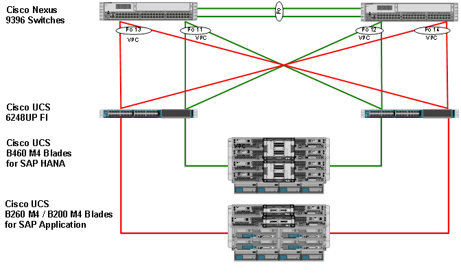
Cisco UCS Server Configuration
This section describes the specific configurations on Cisco UCS servers to address SAP HANA requirements.
Initial Setup of Cisco UCS 6332 Fabric Interconnect
This section provides the detailed procedures to configure the Cisco Unified Computing System (Cisco UCS) for use in FlexPod Datacenter Solution for SAP HANA environment. These steps are necessary to provision the Cisco UCS C-Series and B-Series servers to meet SAP HANA requirements.
Cisco UCS 6332 Fabric Interconnect A
To configure the Cisco UCS Fabric Interconnect A, complete the following steps:
1. Connect to the console port on the first Cisco UCS 6200 Fabric Interconnect.
Enter the configuration method: console
Enter the setup mode; setup newly or restore from backup.(setup/restore)? setup
You have choosen to setup a a new fabric interconnect? Continue? (y/n): y
Enforce strong passwords? (y/n) [y]: y
Enter the password for "admin": <<var_password>>
Enter the same password for "admin": <<var_password>>
Is this fabric interconnect part of a cluster (select 'no' for standalone)? (yes/no) [n]: y
Which switch fabric (A|B): A
Enter the system name: <<var_ucs_clustername>>
Physical switch Mgmt0 IPv4 address: <<var_ucsa_mgmt_ip>>
Physical switch Mgmt0 IPv4 netmask: <<var_ucsa_mgmt_mask>>
IPv4 address of the default gateway: <<var_ucsa_mgmt_gateway>>
Cluster IPv4 address: <<var_ucs_cluster_ip>>
Configure DNS Server IPv4 address? (yes/no) [no]: y
DNS IPv4 address: <<var_nameserver_ip>>
Configure the default domain name? y
Default domain name: <<var_dns_domain_name>>
Join centralized management environment (UCS Central)? (yes/no) [n]: Enter
2. Review the settings printed to the console. If they are correct, answer yes to apply and save the configuration.
3. Wait for the login prompt to make sure that the configuration has been saved.
Cisco UCS 6332 Fabric Interconnect B
To configure the Cisco UCS Fabric Interconnect B, complete the following steps:
1. Connect to the console port on the second Cisco UCS 6248 fabric interconnect.
Enter the configuration method: console
Installer has detected the presence of a peer Fabric interconnect. This Fabric interconnect will be added to the cluster. Do you want to continue {y|n}? y
Enter the admin password for the peer fabric interconnect: <<var_password>>
Physical switch Mgmt0 IPv4 address: <<var_ucsb_mgmt_ip>>
Apply and save the configuration (select ‘no’ if you want to re-enter)? (yes/no): y
2. Wait for the login prompt to make sure that the configuration has been saved.
Cisco UCS for SAP HANA
Log in to Cisco UCS Manager
To log in to the Cisco Unified Computing System (UCS) environment, complete the following steps:
1. Open a web browser and navigate to the Cisco UCS 6332 Fabric Interconnect cluster address.
2. Click the Launch UCS Manager link to download the Cisco UCS Manager software.
3. If prompted to accept security certificates, accept as necessary.
4. When prompted, enter admin as the user name and enter the administrative password.
5. Click Login to log in to Cisco UCS Manager.
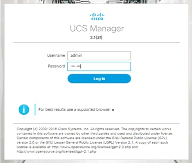
Upgrade Cisco UCS Manager Software to Version 3.1(2f)
This document assumes the use of Cisco UCS Manager Software version 3.1(2f). To upgrade the Cisco UCS Manager software and the UCS 6332 Fabric Interconnect software to version 3.1(2f), refer to Cisco UCS Manager Install and Upgrade Guides.
Add Block of IP Addresses for KVM Access
To create a block of IP addresses for server Keyboard, Video, Mouse (KVM) access in the Cisco UCS environment, complete the following steps:
1. This block of IP addresses should be in the same subnet as the management IP addresses for the Cisco UCS Manager.
2. In Cisco UCS Manager, click the LAN tab in the navigation pane.
3. Select Pools > root > IP Pools > IP Pool ext-mgmt.
4. In the Actions pane, select Create Block of IP Addresses.
5. Enter the starting IP address of the block and the number of IP addresses required, and the subnet and gateway information.
6. Click OK to create the IP block.
7. Click OK in the confirmation message.
Synchronize Cisco UCS to NTP
To synchronize the Cisco UCS environment to the NTP server, complete the following steps:
1. In Cisco UCS Manager, click the Admin tab in the navigation pane.
2. Select All > Timezone Management.
3. In the Properties pane, select the appropriate time zone in the Timezone menu.
4. Click Save Changes, and then click OK.
5. Click Add NTP Server.
6. Enter <<var_global_ntp_server_ip>> and click OK.
7. Click OK.
Cisco UCS Blade Chassis Connection Options
For the Cisco UCS 2300 Series Fabric Extenders, two configuration options are available: pinning and port-channel.
SAP HANA node communicates with every other SAP HANA node using multiple I/O streams and this makes the port-channel option a highly suitable configuration. SAP has defined a single-stream network performance test as part of the hardware validation tool (TDINetServer/TDINetClient).
With the new 40Gb network speed it is also possible to say with the default setting of UCS which is Port-Channel as connection policy.
To run SAP HANA on an infrastructure with two 40Gb uplinks per IOM, use Table 17 through Table 19 to understand the pinning of IOM uplink ports (Port1 to Port4) and vCON. This pinning information is used when the virtual network interface card (vNIC) and virtual host bus adapter (vHBA) placement policy is defined.
Table 17 Cisco UCS 5108 Chassis with Eight Half-Width Blades (such as B200)
| IOM Port1 - vCON1 (Blade 1) |
IOM Port2 - vCON1 (Blade 2) |
| IOM Port3 - vCON1 (Blade 3) |
IOM Port4 - vCON1 (Blade 4) |
| IOM Port1 - vCON1 (Blade 5) |
IOM Port2 - vCON1 (Blade 6) |
| IOM Port3 - vCON1 (Blade 7) |
IOM Port4 - vCON1 (Blade 8) |
Table 18 Cisco UCS 5108 Chassis with Four Full-Width Blades (such as B260)
| IOM Port1 - vCON1 (Blade 1) |
IOM Port2 - vCON2 (Blade 1) |
| IOM Port3 - vCON1 (Blade 2) |
IOM Port4 - vCON2 (Blade 2) |
| IOM Port1 - vCON1 (Blade 3) |
IOM Port2 - vCON2 (Blade 3) |
| IOM Port3 - vCON1 (Blade 4) |
IOM Port4 - vCON2 (Blade 4) |
Table 19 Cisco UCS 5108 Chassis with Two Full-Width Double-High Blades (such as B460)
| IOM Port1 – vCON3 (Blade 1) |
IOM Port2 – vCON4 (Blade 1) |
| IOM Port3 – vCON1 (Blade 1) |
IOM Port4 - vCON2 (Blade 1) |
| IOM Port1 – vCON3 (Blade 2) |
IOM Port2 – vCON4 (Blade 2) |
| IOM Port3 - vCON1 (Blade 2) |
IOM Port4 - vCON2 (Blade 2) |
Edit Chassis Discovery Policy
Setting the discovery policy simplifies the addition of Cisco UCS B-Series chassis and of additional fabric extenders for further C-Series connectivity.
To modify the chassis discovery policy, complete the following steps:
1. In Cisco UCS Manager, click the Equipment tab in the navigation pane and select Equipment in the list on the left.
2. In the right pane, click the Policies tab.
3. Under Global Policies, set the Chassis/FEX Discovery Policy to match the number of uplink ports that are cabled between the chassis or fabric extenders (FEXes) and the fabric interconnects.
4. Set the Link Grouping Preference to “none” for pinning mode.
5. Click Save Changes.
6. Click OK.
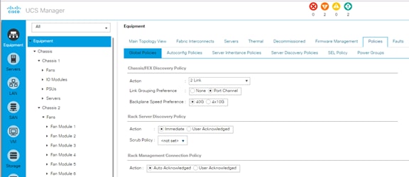
Enable Server and Uplink Ports
To enable server and uplink ports, complete the following steps:
1. In Cisco UCS Manager, click the Equipment tab in the navigation pane.
2. Select Equipment > Fabric Interconnects > Fabric Interconnect A (primary) > Fixed Module.
3. Expand Ethernet Ports.
4. Select the ports that are connected to the chassis and / or to the Cisco C-Series Server (two per FI), right-click them, and select Configure as Server Port.
5. Click Yes to confirm server ports and click OK.
6. Verify that the ports connected to the chassis and / or to the Cisco C-Series Server are now configured as server ports.
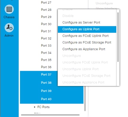
7. Select ports that are connected to the Cisco Nexus switches, right-click them, and select Configure as Uplink Port.
8. Click Yes to confirm uplink ports and click OK.
9. Select Equipment > Fabric Interconnects > Fabric Interconnect B (subordinate) > Fixed Module.
10. Expand Ethernet Ports.
11. Select the ports that are connected to the chassis or to the Cisco C-Series Server (two per FI), right-click them, and select Configure as Server Port.
12. Click Yes to confirm server ports and click OK.
13. Select ports that are connected to the Cisco Nexus switches, right-click them, and select Configure as Uplink Port.
14. Click Yes to confirm the uplink ports and click OK.
Acknowledge Cisco UCS Chassis and Rack-Mount Servers
To acknowledge all Cisco UCS chassis and Rack Mount Servers, complete the following steps:
1. In Cisco UCS Manager, click the Equipment tab in the navigation pane.
2. Expand Chassis and select each chassis that is listed.
3. Right-click each chassis and select Acknowledge Chassis.
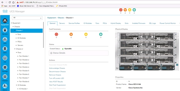
4. Click Yes and then click OK to complete acknowledging the chassis.
5. If C-Series servers are part of the configuration, expand Rack Mounts and FEX.
6. Right-click each Server that is listed and select Acknowledge Server.
7. Click Yes and then click OK to complete acknowledging the Rack Mount Servers
Create Uplink Port Channels to Cisco Nexus Switches
A separate uplink port channel for each of the network zones is defined as per SAP. For example, create port channel 11 on fabric interconnect A and port channel 12 on fabric interconnect B for internal zone network. Create an additional port channel 21 on fabric interconnect A and port channel 22 on fabric interconnect B for backup network; these uplinks are dedicated for backup traffic only. Configure the additional backup storage to communicate with backup VLAN created on Cisco UCS.
To configure the necessary port channels for the Cisco UCS environment, complete the following steps:
1. In Cisco UCS Manager, click the LAN tab in the navigation pane.
2. In this procedure, two port channels are created: one from fabric A to both Cisco Nexus switches and one from fabric B to both Cisco Nexus switches.
3. Under LAN > LAN Cloud, expand the Fabric A tree.
4. Right-click Port Channels.
5. Select Create Port Channel.
6. Enter 11 as the unique ID of the port channel.
7. Enter vPC-41-Nexus as the name of the port channel.
8. Click Next.
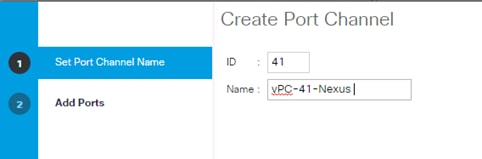
9. Select the following ports to be added to the port channel:
· Slot ID 1 and port 35
· Slot ID 1 and port 36
· Slot ID 1 and port 37
· Slot ID 1 and port 38

10. Click >> to add the ports to the port channel.
11. Click Finish to create the port channel.
12. Click OK.
13. In the navigation pane, under LAN > LAN Cloud, expand the fabric B tree:
a. Right-click Port Channels.
b. Select Create Port Channel.
c. Enter 42 as the unique ID of the port channel.
d. Enter vPC-42-Nexus as the name of the port channel.
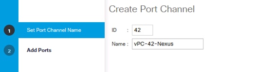
14. Click Next.
15. Select the following ports to be added to the port channel:
· Slot ID 1 and port 35
· Slot ID 1 and port 36
· Slot ID 1 and port 37
· Slot ID 1 and port 38
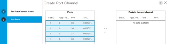
16. Click >> to add the ports to the port channel.
17. Click Finish to create the port channel.
18. Click OK.
![]() For each additional NetApp Storage, four Uplink ports from each Cisco UCS Fabric Interconnect is required. When more than one NetApp storage is configured additional Uplink ports should be included in the Port-Channel 11 on FI A and Port-Channel 12 on FI B.
For each additional NetApp Storage, four Uplink ports from each Cisco UCS Fabric Interconnect is required. When more than one NetApp storage is configured additional Uplink ports should be included in the Port-Channel 11 on FI A and Port-Channel 12 on FI B.
19. Repeat the steps 1-21 to create Additional port-channel for each network zone.
Complete the following steps to create port-channel for backup network:
1. In Cisco UCS Manager, click the LAN tab in the navigation pane.
2. Under LAN > LAN Cloud, expand the Fabric A tree.
3. Right-click Port Channels.
4. Select Create Port Channel (Figure 47).
5. Enter 21 as the unique ID of the port channel.
6. Enter vPC-21-Backup as the name of the port channel.
7. Click Next.
8. 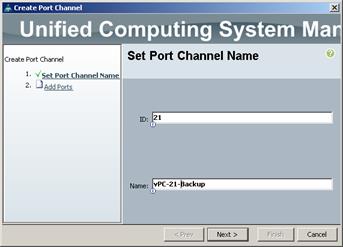
9.
10. Select the following ports to be added to the port channel:
· Slot ID 1 and port 9
· Slot ID 1 and port 11
11. Click >> to add the ports to the port channel.
12. Click Finish to create the port channel.
13. Click OK.
14. In the navigation pane, under LAN > LAN Cloud, expand the fabric B tree.
15. Right-click Port Channels.
16. Select Create Port Channel.
17. Enter 22 as the unique ID of the port channel.
18. Enter vPC-21-Backup as the name of the port channel.
19. Click Next.
20. Select the following ports to be added to the port channel:
· Slot ID 1 and port 9
· Slot ID 1 and port 11
21. Click >> to add the ports to the port channel.
22. Click Finish to create the port channel.
23. Click OK.
Create New Organization
For secure multi-tenancy within the Cisco UCS domain, a logical entity is created as Organizations.
To create organization unit, complete the following steps:
1. In Cisco UCS Manager, on the Servers bar.
2. Select Servers and right click on root and select Create Organization.
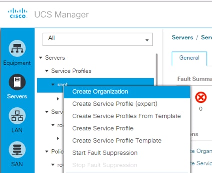
3. Enter the Name as HANA.
4. Optional Enter the Description as Org for HANA.
5. Click OK to create the Organization.
Create MAC Address Pools
To configure the necessary MAC address pools for the Cisco UCS environment, complete the following steps:
1. In Cisco UCS Manager, click the LAN tab in the navigation pane.
2. Select Pools > root > Sub-Organization > HANA.
3. In this procedure, two MAC address pools are created, one for each switching fabric.
4. Right-click MAC Pools under the root organization.
5. Select Create MAC Pool to create the MAC address pool .
6. Enter MAC_Pool_A as the name of the MAC pool.
7. Optional: Enter a description for the MAC pool.
8. Choose Assignment Order Sequential.
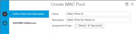
9. Click Next.
10. Click Add.
11. Specify a starting MAC address.
12. The recommendation is to place 0A in the fourth octet of the starting MAC address to identify all of the MAC addresses as Fabric Interconnect A addresses.
13. Specify a size for the MAC address pool that is sufficient to support the available blade or server resources.
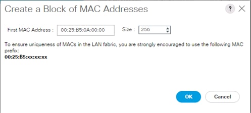
14. Click OK.
15. Click Finish.
16. In the confirmation message, click OK.
17. Right-click MAC Pools under the HANA organization.
18. Select Create MAC Pool to create the MAC address pool .
19. Enter MAC_Pool_B as the name of the MAC pool.
20. Optional: Enter a description for the MAC pool.
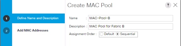
21. Click Next.
22. Click Add.
23. Specify a starting MAC address.
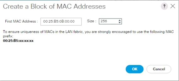
![]() The recommendation is to place 0B in the fourth octet of the starting MAC address to identify all the MAC addresses in this pool as fabric B addresses.
The recommendation is to place 0B in the fourth octet of the starting MAC address to identify all the MAC addresses in this pool as fabric B addresses.
24. Specify a size for the MAC address pool that is sufficient to support the available blade or server resources.
25. Cisco UCS - Create MAC Pool for Fabric B.
26. Click OK.
27. Click Finish.
28. In the confirmation message, click OK.
Create UUID Suffix Pool
To configure the necessary universally unique identifier (UUID) suffix pool for the Cisco UCS environment, complete the following steps:
1. In Cisco UCS Manager, click the Servers tab in the navigation pane.
2. Select Pools > root.
3. Right-click UUID Suffix Pools.
4. Select Create UUID Suffix Pool.
5. Enter UUID_Pool as the name of the UUID suffix pool.
6. Optional: Enter a description for the UUID suffix pool.
7. Keep the Prefix as the Derived option.
8. Select Sequential for Assignment Order
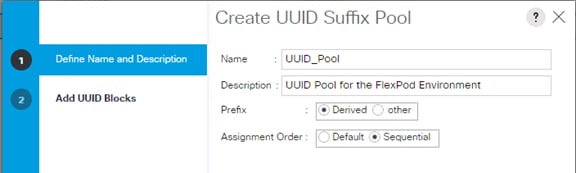
9. Click Next.
10. Click Add to add a block of UUIDs.
11. Keep the From field at the default setting.
12. Specify a size for the UUID block that is sufficient to support the available blade or server resources.

13. Click OK.
14. Click Finish.
15. Click OK.
Server Pool for SAP HANA
Server configuration to run SAP HANA is defined by SAP. Within Cisco UCS, it is possible to specify a policy to pull in all servers for SAP HANA in a pool.
Create Server Pool Policy Qualifications
To configure the qualification for server pool, complete the following steps:
![]() Consider creating unique server pools for each type of HANA servers. The following steps show qualifications for Cisco UCS B460 M4 Server with 1TB RAM and Intel E7-8890 Processors for HANA.
Consider creating unique server pools for each type of HANA servers. The following steps show qualifications for Cisco UCS B460 M4 Server with 1TB RAM and Intel E7-8890 Processors for HANA.
1. In Cisco UCS Manager, click the Servers tab in the navigation pane.
2. Select Policies > Server Pool Policy Qualifications.
3. Right-click Server Pool Policy Qualifications.
4. Select Create Server Pool Policy Qualifications.
5. Enter HANA-1TB as the name of the server pool.
6. Optional: Enter a description for the server pool policy qualification.
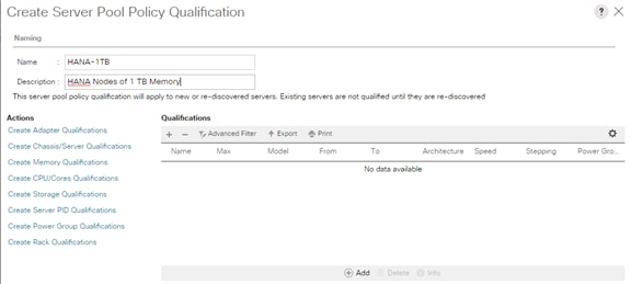
7. In the Actions panel click on Create Memory Qualifications.
8. On Min Cap (MB) choose select button and enter 1048576 (for B260-M4 with 512 GB memory use 524288).
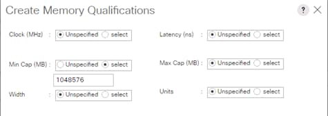
9. Click OK.
10. In the Actions panel click on Create CPU/Cores Qualifications.
11. On Min Number of Cores choose select button and enter 60 (for B260-M4 with 2 Socket choose 30).
12. On Min Number of Threads choose select button and enter 120 (for B260-M4 with 2 Socket choose 60).
13. On CPU Speed (MHz) choose select button and enter 2800.
14. Click OK.
15. Click OK.
16. Click OK.
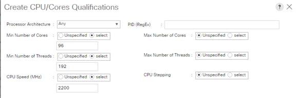
Create Server Pool
To configure the necessary server pool for the Cisco UCS environment, complete the following steps:
1. Consider creating unique server pools to achieve the granularity that is required in your environment.
2. In Cisco UCS Manager, click the Servers tab in the navigation pane.
3. Select Pools > root.
4. Right-click Server Pools.
5. Select Create Server Pool.
6. Enter HANA-1TB-8890 as the name of the server pool.
7. Optional: Enter a description for the server pool.
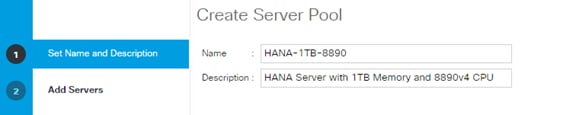
8. Click Next.
9. Add the servers to the server pool.
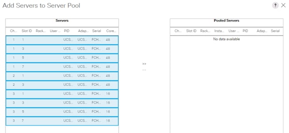
10. Click Finish.
11. Click OK.
Cisco Server Pool Policy
The server pool for the SAP HANA nodes and its qualification policy are defined. To map the two server pool policies, complete the following steps:
1. In Cisco UCS Manager, click the Servers tab in the navigation pane.
2. Select Policies > Server Pool Policies.
3. Right-click Server Pool Policy.
4. Select Create Server Pool Policy.
5. Enter HANA-1TB as the name of the server pool.
6. For Target Pool choose HANA-1TB-4890 Server Pool created from the drop-down menu.
7. For Qualification choose HANA-1TB Server Pool Policy Qualifications created from the drop-down menu
8. Click OK.
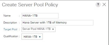
![]() As a result, all the servers with the specified qualification are now available in the server pool as shown in the following screenshot.
As a result, all the servers with the specified qualification are now available in the server pool as shown in the following screenshot.
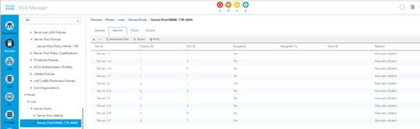
Power Policy
To run Cisco UCS with two independent power distribution units, the redundancy must be configured as Grid. Complete the following steps:
1. In Cisco UCS Manager, click the Equipment tab in the navigation pane and select Equipment in the list on the left.
2. In the right pane, click the Policies tab.
3. Under Global Policies, set the Power Policy to “Grid.”
4. Click Save Changes.
5. Click OK.
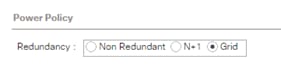
Power Control Policy
The Power Capping feature in Cisco UCS is designed to save power with a legacy data center use cases. This feature does not contribute much to the high performance behavior of SAP HANA. By choosing the option “No Cap” for power control policy, the SAP HANA server nodes will not have a restricted power supply. It is recommended to have this power control policy to ensure sufficient power supply for high performance and critical applications like SAP HANA.
To create a power control policy for the Cisco UCS environment, complete the following steps:
1. In Cisco UCS Manager, click the Servers tab in the navigation pane.
2. Select Policies > root.
3. Right-click Power Control Policies.
4. Select Create Power Control Policy.
5. Enter HANA as the power control policy name.
6. Change the power capping setting to No Cap.
7. Click OK to create the power control policy.
8. Click OK.
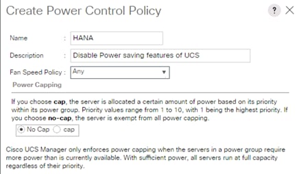
Create Host Firmware Package
Firmware management policies allow the administrator to select the corresponding packages for a given server configuration. These policies often include packages for adapter, BIOS, board controller, FC adapters, host bus adapter (HBA) option ROM, and storage controller properties.
To create a firmware management policy for a given server configuration in the Cisco UCS environment, complete the following steps:
1. In Cisco UCS Manager, click the Servers tab in the navigation pane.
2. Select Policies > root.
3. Right-click Host Firmware Packages.
4. Select Create Host Firmware Package.
5. Enter HANA-FW as the name of the host firmware package.
6. Leave Simple selected.
7. Select the version 3.1(2f) for both the Blade and Rack Packages.
8. Mark all checkpoints to select all available modules
9. Click OK to create the host firmware package.
10. Click OK.
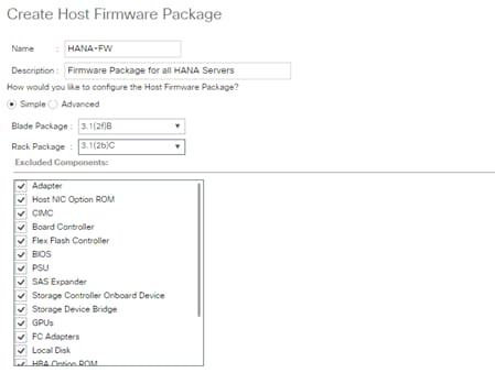
Create Local Disk Configuration Policy (Optional)
A local disk configuration for the Cisco UCS environment is necessary if the servers in the environment do not have a local disk.
![]() This policy should not be used on servers that contain local disks.
This policy should not be used on servers that contain local disks.
To create a local disk configuration policy, complete the following steps:
1. In Cisco UCS Manager, click the Servers tab in the navigation pane.
2. Select Policies > root.
3. Right-click Local Disk Config Policies.
4. Select Create Local Disk Configuration Policy.
5. Enter No-Local as the local disk configuration policy name.
6. Change the mode to No Local Storage.
7. Click OK to create the local disk configuration policy.
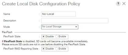
8. Click OK.
Create Server BIOS Policy
To get best performance for HANA it is required to configure the Server BIOS accurately. To create a server BIOS policy for the Cisco UCS environment, complete the following steps:
1. In Cisco UCS Manager, click the Servers tab in the navigation pane.
2. Select Policies > root > Sub-Organization > HANA.
3. Right-click BIOS Policies.
4. Select Create BIOS Policy.
5. Enter HANA-BIOS as the BIOS policy name.
6. Change the Quiet Boot setting to Disabled.
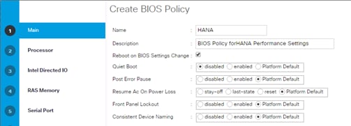
7. Click Next.
![]() The recommendation from SAP for SAP HANA is to disable all Processor C States. This will force the CPU to stay on maximum frequency and allow SAP HANA to run with best performance.
The recommendation from SAP for SAP HANA is to disable all Processor C States. This will force the CPU to stay on maximum frequency and allow SAP HANA to run with best performance.
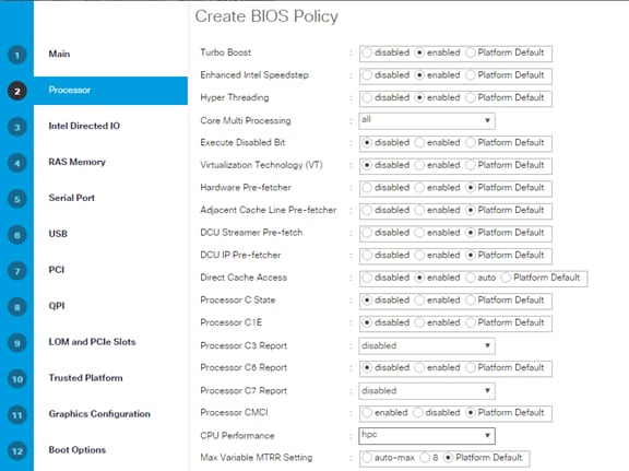
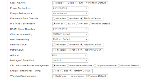
8. Click Next.
9. No changes required at the Intel Direct IO.
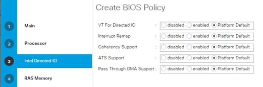
10. Click Next.
11. In the RAS Memory please select maximum-performance and enable NUMA.
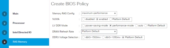
12. Click Next.
13. In the Serial Port Tab the Serial Port A must be enabled.
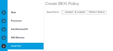
14. Click Next.
15. No changes required at the USB settings.
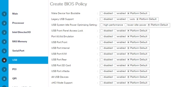
16. Click Next.
17. No changes required at the PCI Configuration.
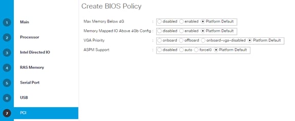
18. Click Next.
19. No changes required for the QPI.
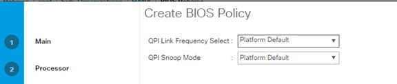
20. Click Next.
21. No changes required for LOM and PCIe Slots.
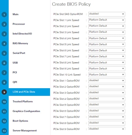
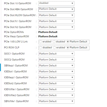
22. Click Next.
23. Disable the Secure Platform Module Options.
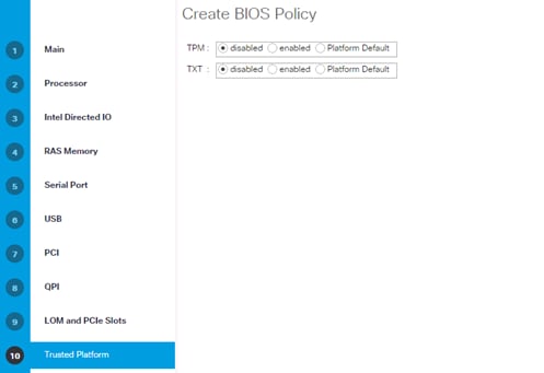
24. Click Next.
25. No changes required on the Graphical Configuration.
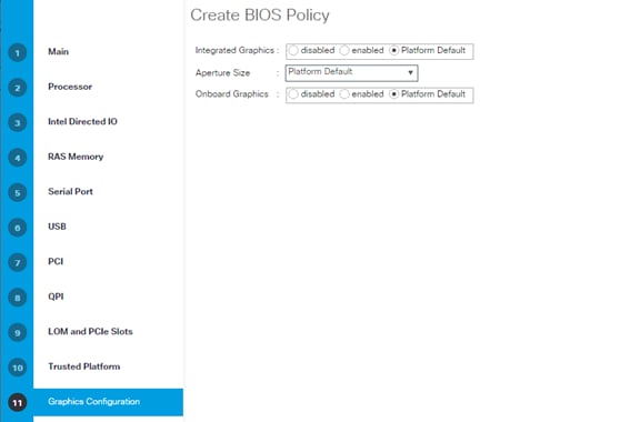
26. No changes required for the Boot Options.
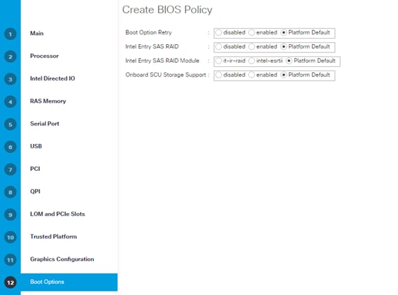
27. Click Next.
28. Configure the Console Redirection to serial-port-a with the BAUD Rate 115200 and enable the feature Legacy OS redirect. This is used for Serial Console Access over LAN to all SAP HANA servers.
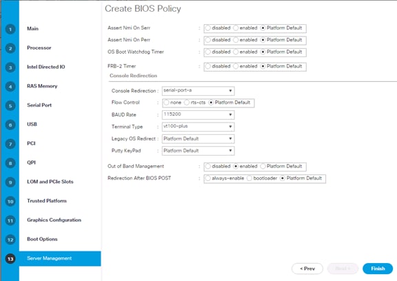
29. Click Finish to Create BIOS Policy.
30. Click OK.
Create Serial Over LAN Policy
The Serial over LAN policy is required to get console access to all the SAP HANA servers through SSH from the management network. This is used if the server hangs or there is a Linux kernel crash, where the dump is required. To configure the speed in the Server Management tab of the BIOS Policy, complete the following steps:
1. In Cisco UCS Manager, click the Servers tab in the navigation pane.
2. Select Policies > root > Sub-Organization > HANA.
3. Right-click Serial over LAN Policies.
4. Select Create Serial over LAN Policy.
5. Enter SoL-Console as the Policy name.
6. Select Serial over LAN State to enable.
7. Change the Speed to 115200.
8. Click OK.
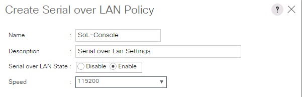
Update Default Maintenance Policy
It is recommended to update the default Maintenance Policy with the Reboot Policy “User Ack” for the SAP HANA server. This policy will wait for the administrator to acknowledge the server reboot for the configuration changes to take effect.
To update the default Maintenance Policy, complete the following steps:
1. In Cisco UCS Manager, click the Servers tab in the navigation pane.
2. Select Policies > root.
3. Select Maintenance Policies > default.
4. Change the Reboot Policy to User Ack.
5. Click Save Changes.
6. Click OK to accept the change.
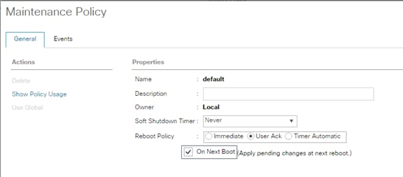
IPMI Access Profiles
The Serial over LAN access requires an IPMI access control to the board controller. This is also used for the STONITH function of the SAP HANA mount API to kill a hanging server. The default user is 'sapadm' with the password 'cisco'.
To create an IPMI Access Profile, complete the following steps:
1. In Cisco UCS Manager, click the Servers tab in the navigation pane.
2. Select Policies > root > Sub-Organization > HANA.
3. Right-click IPMI Access Profiles.
4. Select Create IPMI Access Profile
5. Enter HANA-IPMI as the Profile name.
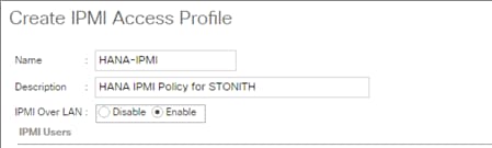
6. Click the + (add) button.
7. Enter Username in the Name field and password.
8. Select Admin as Role.
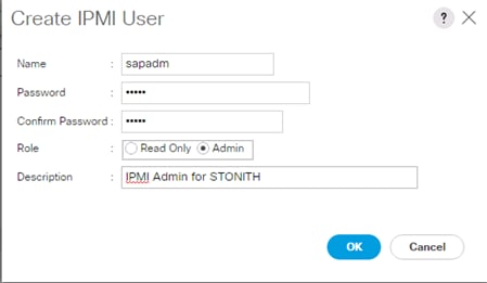
9. Click OK to create user.
10. Click OK to Create IPMI Access Profile.
11. Click OK.
Adapter Policy Configuration
This section describes the Ethernet Adapter Policy with optimized RSS, Receive Queues and Interrupts values. This policy must be used for the SAP HANA internal network to provide best network performance.
To create an Ethernet Adapter Policy, complete the following steps:
1. In Cisco UCS Manager, click the Servers tab in the navigation pane.
2. Select Policies > root > Sub-Organization > HANA.
3. Right-click Adapter Policies.
4. Select Create Ethernet Adapter Policy.
5. Enter Linux-B460 as the Ethernet Adapter policy name.
6. Expand Resources > Change the Receive Queues to 8.
7. Change the Interrupts to 11.
8. Expand Options > Change Receive Side Scaling (RSS) to Enabled.
9. Change Accelerated Receive Flow Steering to Enabled.
10. Click OK to create the Ethernet Adapter policy.
11. Click OK.
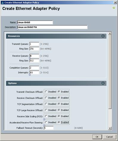
Network Configuration
The core network requirements for SAP HANA are covered by Cisco UCS defaults. Cisco UCS is based on 40-GbE and provides redundancy via the Dual Fabric concept. The Service Profile is configured to distribute the traffic across Fabric Interconnect A and B. During normal operation, the traffic in the Internal Zone and the Data base NFS data traffic is on FI A and all the other traffic (Client Zone and Database NFS log) is on FI B. The inter-node traffic flows from a Blade Server to the Fabric Interconnect A and back to other Blade Server. All the other traffic must go over the Cisco Nexus 9000 switches to storage or to the data center network. With the integrated algorithms for bandwidth allocation and quality of service the Cisco UCS and Cisco Nexus distributes the traffic in an efficient way.
Set Jumbo Frames in Cisco UCS Fabric
To configure jumbo frames and enable quality of service in the Cisco UCS fabric, complete the following steps:
1. In Cisco UCS Manager, click the LAN tab in the navigation pane.
2. Select LAN > LAN Cloud > QoS System Class.
3. In the right pane, click the General tab.
4. On the MTU Column, enter 9216 in the box.
5. Check Enabled Under Priority for Platinum.
6. Click Save Changes in the bottom of the window.
7. Click OK.
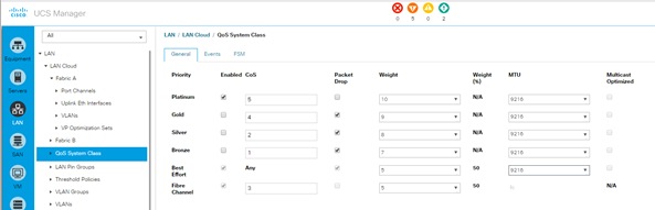
LAN Tab Configurations
Within Cisco UCS, all the network types for an SAP HANA system are reflected by defined VLANs. Network design from SAP has seven SAP HANA related networks and two infrastructure related networks. The VLAN IDs can be changed if required to match the VLAN IDs in the data center network – for example, ID 224 for backup should match the configured VLAN ID at the data center network switches. Even though nine VLANs are defined, VLANs for all the networks are not necessary if the solution will not use the network. For example, if the Replication Network is not used in the solution, then VLAN ID 300 does not have to be created.
Create VLANs
To configure the necessary VLANs for the Cisco UCS environment, complete the following steps:
1. In Cisco UCS Manager, click the LAN tab in the navigation pane.
![]() In this procedure, Nine VLANs are created.
In this procedure, Nine VLANs are created.
2. Select LAN > LAN Cloud.
3. Right-click VLANs.
4. Select Create VLANs.
5. Enter HANA-Boot as the name of the VLAN to be used for PXE boot network.
6. Keep the Common/Global option selected for the scope of the VLAN.
7. Enter <<var_boot_vlan_id>> as the ID of the PXE boot network.
8. Keep the Sharing Type as None.
9. Click OK and then click OK again.
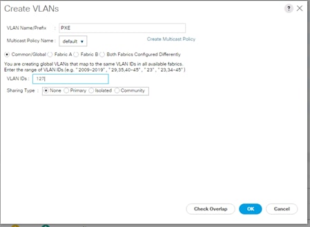
10. Repeat steps 1-9 for each VLAN.
The following are the VLAN’s used in this CVD:
|
|
|
|
|
Figure 14 shows the overview of VLANs created.
Figure 14 VLAN Definition in Cisco UCS
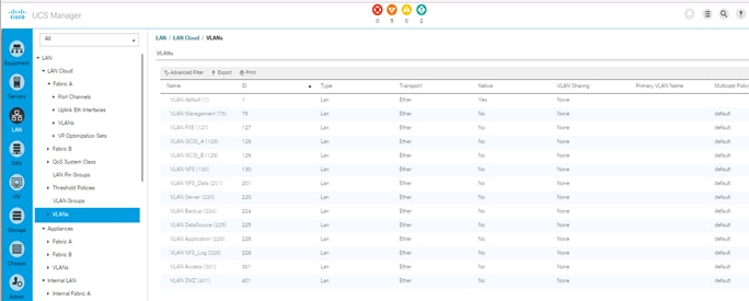
Create VLAN Groups
For easier management and bandwidth allocation to a dedicated uplink on the Fabric Interconnect, VLAN Groups are created within Cisco UCS. The FlexPod Datacenter Solution for SAP HANA uses the following VLAN groups:
· Admin Zone
· Client Zone
· Internal Zone
· Backup Network
· Replication Network
To configure the necessary VLAN Groups for the Cisco UCS environment, complete the following steps:
1. In Cisco UCS Manager, click the LAN tab in the navigation pane.
![]() In this procedure, five VLAN Groups are created. Based on the solution requirement create VLAN groups, it not required to create all five VLAN groups.
In this procedure, five VLAN Groups are created. Based on the solution requirement create VLAN groups, it not required to create all five VLAN groups.
2. Select LAN > LAN Cloud.
3. Right-click VLAN Groups
4. Select Create VLAN Groups.
5. Enter Admin-Zone as the name of the VLAN Group used for Infrastructure network.
6. Select HANA-Admin.
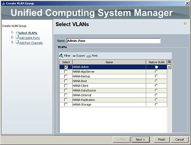
7. Click Next.
8. Click Next on Add Uplink Ports, since you will use Port-Channel.
9. Choose Port-Channels Create for Admin Network.
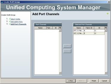
10. Click Finish.
11. Follow the steps 1-10 for each VLAN Group.
12. Create VLAN Groups for Internal Zone.
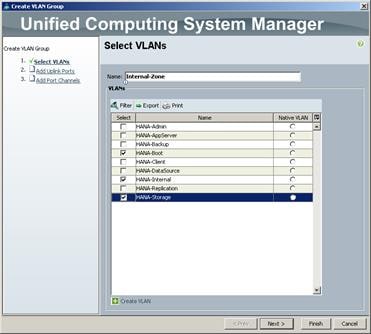
13. Create VLAN Groups for Client Zone.
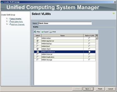
14. Create VLAN Groups for Backup Network.
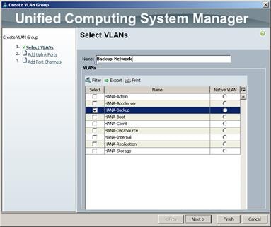
15. Click Next.
16. Click Next on Add Uplink Ports, since we will use Port-Channel.
17. Choose Port-Channels created for Backup Network.
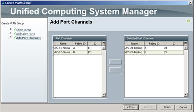
18. Click Finish.
19. Create VLAN Groups for Replication Network.
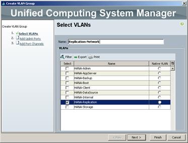
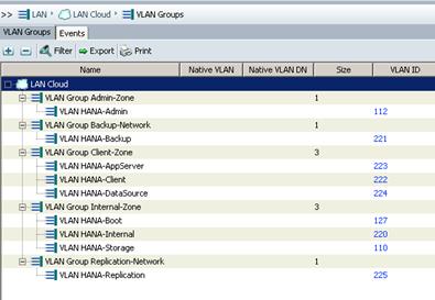
![]() For each VLAN Group a dedicated or shared Ethernet Uplink Port or Port Channel can be selected.
For each VLAN Group a dedicated or shared Ethernet Uplink Port or Port Channel can be selected.
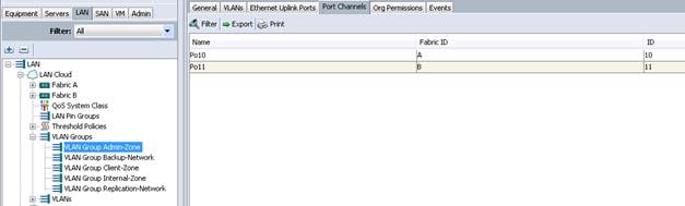
Create QoS Policies
QoS policies assign a system class to the network traffic for a vNIC. To create for the Cisco UCS environment, complete the following steps:
1. In Cisco UCS Manager, click the LAN tab in the navigation pane.
2. Select Policies > root > Sub-Organization > HANA.
3. Right-click QoS Policies.
4. Select Create QoS Policy.
5. Enter Platinum as the QoS Policy name.
6. For Priority Select Platinum from the dropdown list.
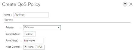
7. Click OK to create the Platinum QoS Policy.
Create vNIC Template
Each VLAN is mapped to a vNIC template to specify the characteristic of a specific network. The vNIC template configuration settings include MTU size, Failover capabilities and MAC-Address pools.
To create vNIC templates for the Cisco UCS environment, complete the following steps:
Create vNIC template for Network (PXE Boot)
1. In Cisco UCS Manager, click the LAN tab in the navigation pane.
2. Select Policies > root > Sub-Organization > HANA.
3. Right-click vNIC Templates.
4. Select Create vNIC Template (Figure 97).
5. Enter PXE as the vNIC template name.
6. Keep Fabric A selected.
7. Select the Enable Failover checkbox.
8. Under Target, make sure that the VM checkbox is not selected.
9. Select Updating Template as the Template Type.
10. Under VLANs, select the checkboxes for PXE
11. Set PXE as the native VLAN.
12. For MTU, enter 1500.
13. In the MAC Pool list, select PXE.
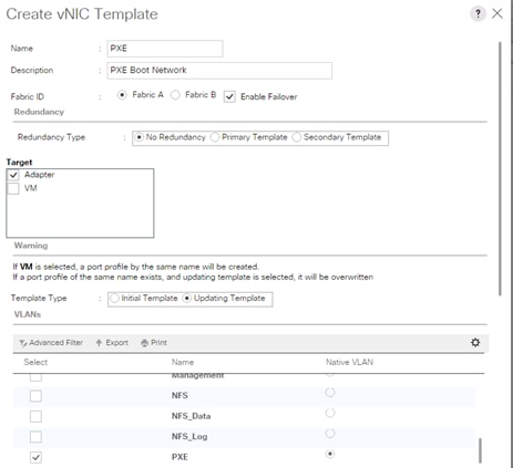
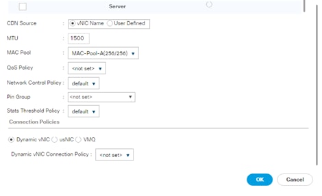
14. Click OK to create the vNIC template.
15. Click OK.
![]() For most SAP HANA use cases, the network traffic is well distributed across the two Fabrics (Fabric A and Fabric B) using the default setup. In special cases, it can be required to rebalance this distribution for better overall performance. This can be done in the vNIC template with the Fabric ID setting. The MTU settings must match the configuration in customer data center. MTU setting of 9000 is recommended for the best performance.
For most SAP HANA use cases, the network traffic is well distributed across the two Fabrics (Fabric A and Fabric B) using the default setup. In special cases, it can be required to rebalance this distribution for better overall performance. This can be done in the vNIC template with the Fabric ID setting. The MTU settings must match the configuration in customer data center. MTU setting of 9000 is recommended for the best performance.
16. Repeat steps 1-15 to create vNIC template for each Network zone.
Create vNIC template for Internal Network (Server-Server)
![]() Internal Network requires >9.0 Gbps for SAP HANA inter-node communication; choose Platinum QoS Policy created for HANA-Internal vNIC Template.
Internal Network requires >9.0 Gbps for SAP HANA inter-node communication; choose Platinum QoS Policy created for HANA-Internal vNIC Template.
Fill-in the following screenshots as follows:
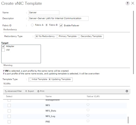
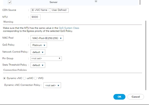
Create vNIC Template for Storage NFS Data Network
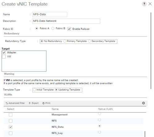

Create vNIC Template for Storage NFS Log Network
17.
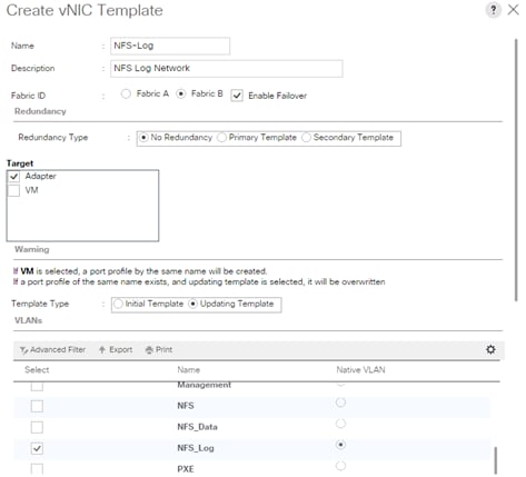
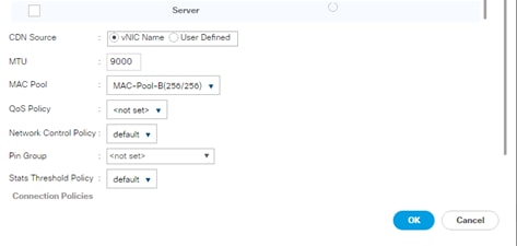
Create vNIC Template for Admin Network
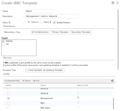
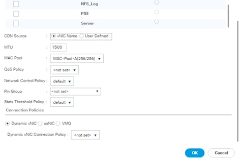
Create vNIC Template for AppServer Network
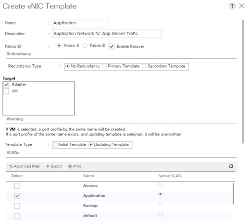
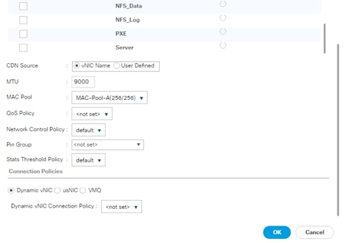
Create vNIC Template for Backup Network
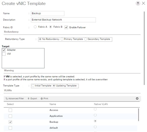
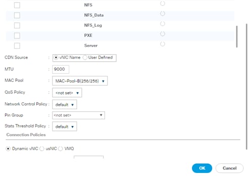
Create vNIC Template for Access Network
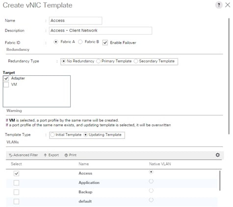

Create vNIC template for DataSource Network
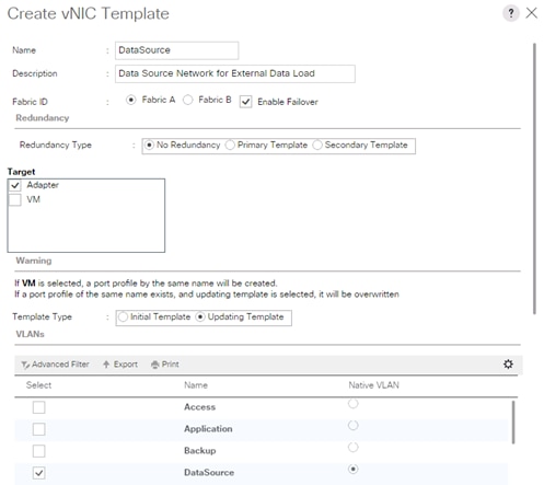
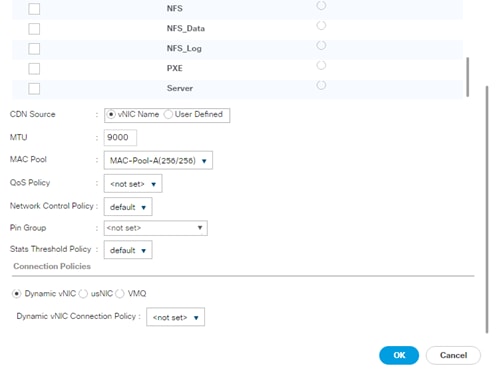
Create vNIC Template for Replication Network
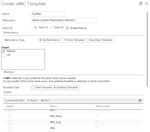

Create vNIC Template for normal NFS traffic
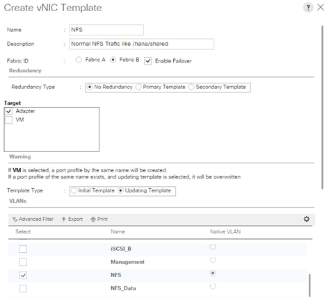
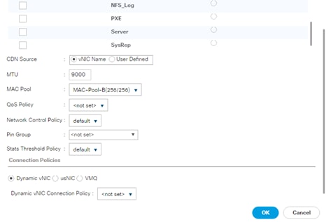
Create vNIC Template for iSCSI via Fabric A
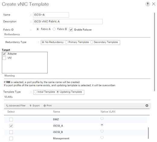
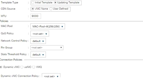
Create vNIC Template for iSCSI via Fabric B
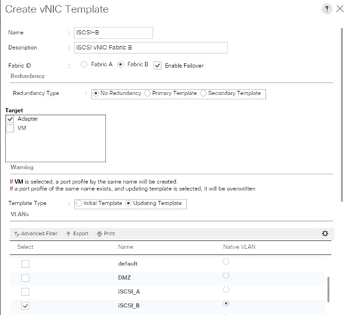
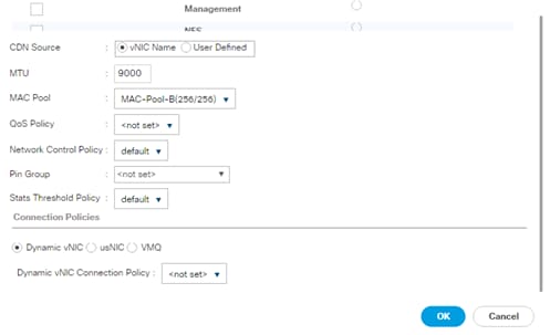
vNIC Templates Overview for SAP HANA
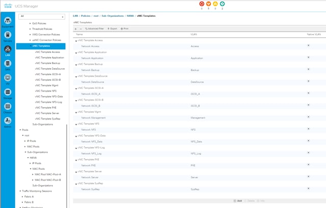
Create vNIC/vHBA Placement Policy
To create a vNIC/vHBA placement policy for the SAP HANA hosts, complete the following steps:
![]() For Cisco UCS B-Series with four VIC cards (2 x VIC 1340 and 2 x VIC 1380).
For Cisco UCS B-Series with four VIC cards (2 x VIC 1340 and 2 x VIC 1380).
1. In Cisco UCS Manager, click the Servers tab in the navigation pane.
2. Select Policies > root > Sub-Organization > HANA.
3. Right-click vNIC/vHBA Placement Policies.
4. Select Create Placement Policy.
5. Enter HANA as the name of the placement policy.
6. Click 1 and select Assigned Only.
7. Click 2 and select Assigned Only.
8. Click 3 and select Assigned Only.
9. Click 4 and select Assigned Only.
10. Click OK and then click OK again.
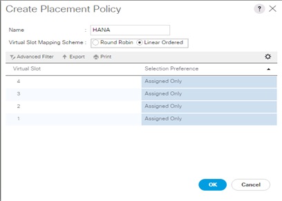
Create PXE Boot Policies
To create PXE boot policies, complete the following steps:
1. In Cisco UCS Manager, click the Servers tab in the navigation pane.
2. Select Policies > root > Sub-Organization > HANA.
3. Right-click Boot Policies.
4. Select Create Boot Policy.
5. Enter PXE-Boot as the name of the boot policy.
6. Optional: Enter a description for the boot policy.
7. Check the Reboot on Boot Order Change option.
8. Expand the Local Devices drop-down menu and select Add CD/DVD.
9. Expand the vNICs section and select Add LAN Boot.
10. In the Add LAN Boot dialog box, enter HANA-Boot.
11. Click OK.
12. Click OK.
13. Click OK to save the boot policy. Click OK to close the Boot Policy window.
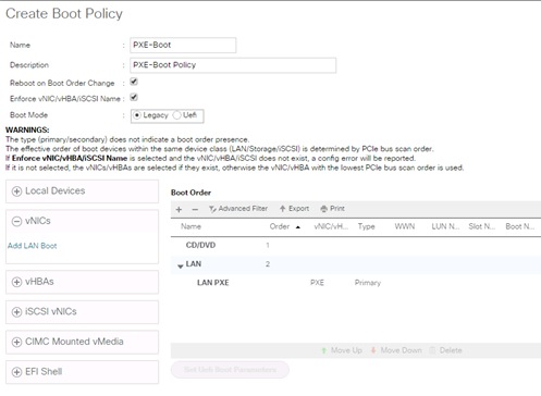
Create Service Profile Templates Bare Metal SAP HANA Scale-Out
The LAN configurations and relevant SAP HANA policies must be defined prior to creating, a Service Profile Template.
To create the service profile template, complete the following steps:
1. In Cisco UCS Manager, click the Servers tab in the navigation pane.
2. Select Service Profile Templates > root > Sub-Organization > HANA.
3. Right-click on HANA.
4. Select Create Service Profile Template (Expert) to open the Create Service Profile Template wizard.
5. Identify the service profile template:
a. Enter HANA-B260 as the name of the service profile template.
b. Select the Updating Template option.
c. Under UUID, select HANA-UUID as the UUID pool.
d. Click Next.
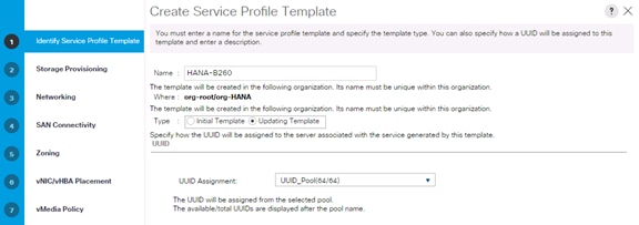
6. Configure the Local Storage Options:
a. Keep the default setting for Specific Storage Profile.
b. Select No storage Profile in the Storage Profile Policy tab.
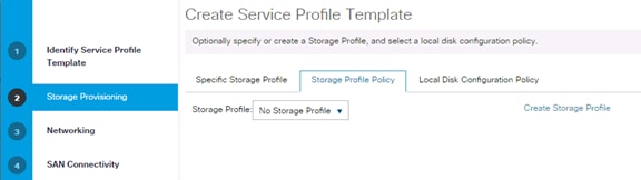
c. Select Local Disk Configuration Policy and set No-Local-Storage.
d. Click Next.
Figure 1. Storage Provisioning
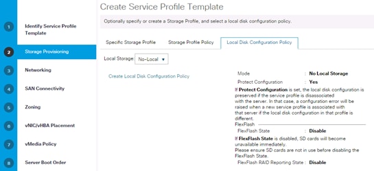
7. Configure the networking options:
a. Keep the default setting for Dynamic vNIC Connection Policy.
b. Select the Expert option to configure the LAN connectivity.
c. Click the upper Add button to add a vNIC to the template.
d. In the Create vNIC dialog box, enter HANA-Boot as the name of the vNIC.
e. Select the Use vNIC Template checkbox.
f. In the vNIC Template list, select HANA-Boot
g. In the Adapter Policy list, select Linux-B460.
h. Click OK to add this vNIC to the template.
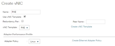
8. Repeat the above steps c-h for each vNIC.
9. Add vNIC for HANA-Server-Server.
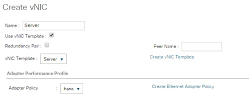
10. Add vNIC for HANA-NFS-Data Storage.
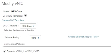
11. Add vNIC for HANA-NFS-Log-Storage.
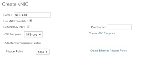
12. Add vNIC for HANA-Access.
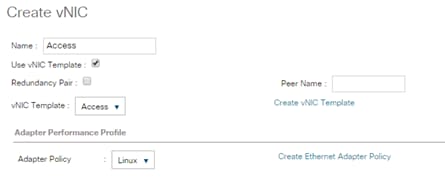
13. Add vNIC for HANA-AppServer.
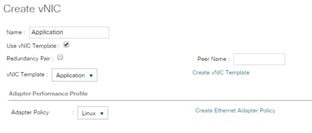
14. Add vNIC for HANA-System-Replication.
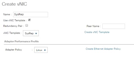
15. Add vNIC for HANA-Backup.
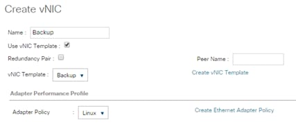
16. Add vNIC for normal NFS traffic.
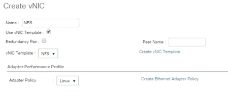
17. Add vNIC for HANA-Admin.
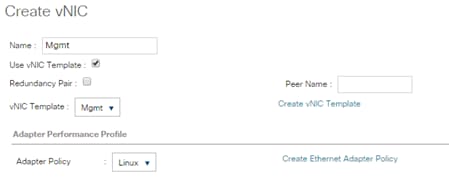
18. Review the table in the Networking page to make sure that all vNICs were created. Decide if you need the optional NIC’s in the configuration.
19. Click Next.
20. Set no Zoning options and click Next.
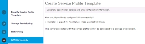
21. Set the vNIC/vHBA placement options.
22. For Cisco UCS B260 M4 and C460 M4 servers:
a. In the “Select Placement” list, select the HANA-B260 placement policy.

23.
a. Select vCon1 and assign the vNICs to the virtual network interfaces policy in the following order:
i. PXE
ii. NFS-Data
iii. Management
iv. Access
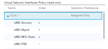
b. Select vCon2 and assign the vNICs to the virtual network interfaces policy in the following order:
i. Application
ii. Backup
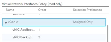
c. Click Next.
d. Select vCon3 and assign the vNICs to the virtual network interfaces policy in the following order:
iii. NFS-Log
iv. SysRep
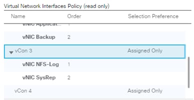
e. Click Next.
f. Select vCon4 and assign the vNICs to the virtual network interfaces policy in the following order:
i. NFS
ii. Server
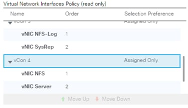
g. Click Next.
24. No change required on the vMedia Policy, click Next.
25. Set the server boot order:
a. Select PXE-Boot for Boot Policy.
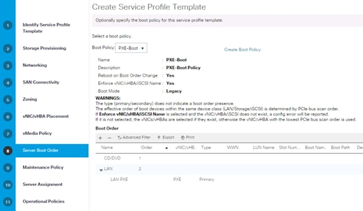
b. Click Next.
26. Add a maintenance policy:
a. Select the default Maintenance Policy.
b. Click Next.
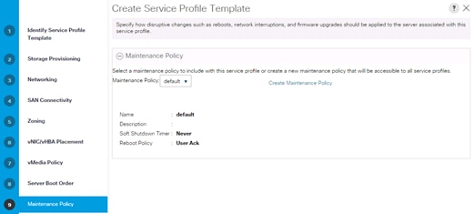
27. Specify the server assignment:
a. In the Pool Assignment list, select HANA-1TB.
b. Optional: Select a Server Pool Qualification policy HANA-1TB
c. Or simply say assign later
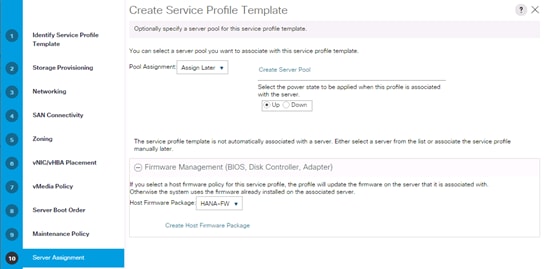
d. Select the HANA-Firmware Policy by selecting HANA-FW.
e. Click Next.
28. Set Operational Policies:
a. Select the HANA Bios Policy
b. Select the IPMI Access Profile
c. Select the Serial over LAN Console
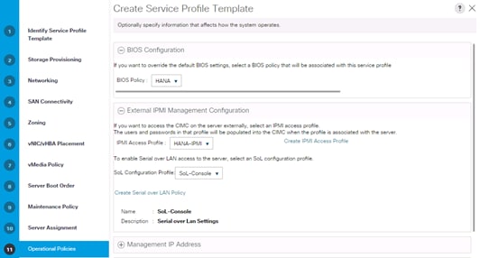
29. Configure the Setting Operational Policies:
a. Click Create Outband Management Pool.
b. Specify the name of the Out of band management pool.
c. Select Sequential Order.
d. Click Next.
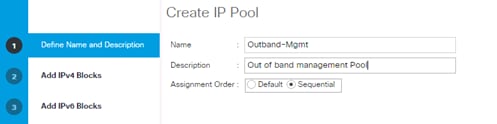
e. Define the out of band management ip pool (mgmt. VLAN).
f. Define the size of the IP pool.
g. Specify the default GW and the DNS server (if available).
h. Click Next.
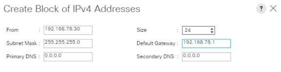
i. Do not specify IPv6 IP addresses for the management pool.
j. Click Finish.
30. Configure the Setting Operational Policies:
a. Select the management pool you just created.
b. Select the default monitoring thresholds.
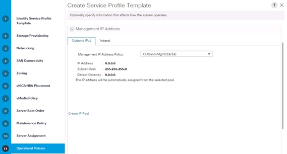
c. Select the HANA policy for the Power Control Configuration.
d. Leave the two other fields as default.
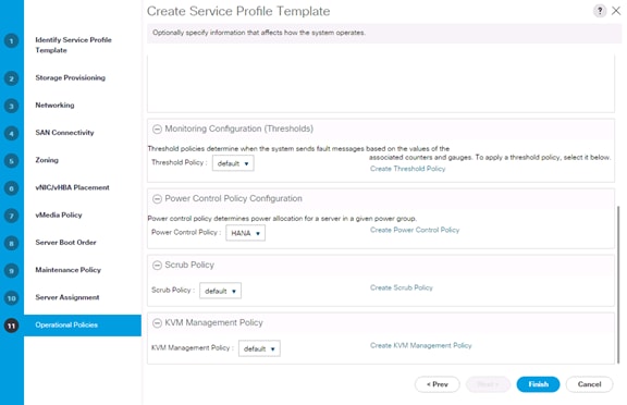
31. Complete the service profile generation by clicking Finish.
Create Service Profile Templates Bare Metal SAP HANA iSCSI
To create the service profile template for SAP HANA for iSCSI boot for both SUSE and RedHat implementations, complete the following steps:
1. In Cisco UCS Manager, click the Servers tab in the navigation pane.
2. Select Service Profile Templates > root > Sub-Organization > HANA.
3. Right-click HANA.
4. Select Create Service Profile Template to open the Create Service Profile Template wizard.
5. Identify the service profile template:
a. Enter HANA-iSCSI as the name of the service profile template.
b. Select the Updating Template option.
c. Under UUID, select HANA-UUID as the UUID pool.
d. Click Next.
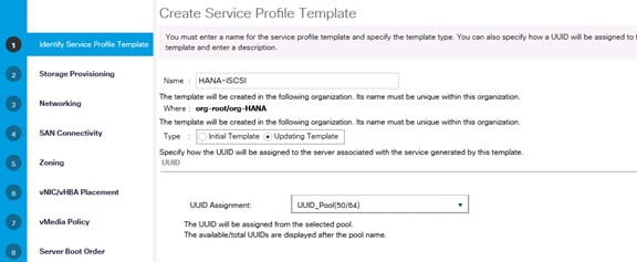
6. Configure the Storage Provisioning:
a. Select “No Storage Profile” under Storage Profile Policy.
b. Select “No-Local” under Local Disk Configuration Policy.
c. Click Next.
7. Network configuration.
a. Select “No Dynamic VNIC policy”.
b. Select Expert Configuration.
c. Add the necessary networks.
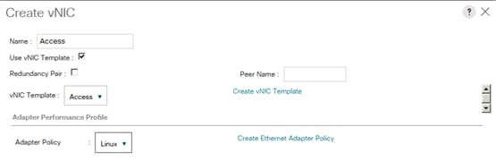
Figure 15 Backup Network
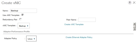
Figure 16 Management Network
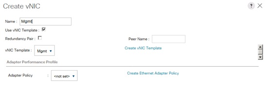
Figure 17 NFS-Data Network
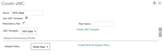
Figure 18 NFS-Log Network
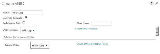
Figure 19 Server-Server Network (Optional)
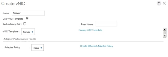
8. Click add vNIC and create the two iSCSI vNICs.
Figure 20 Create iSCSI A
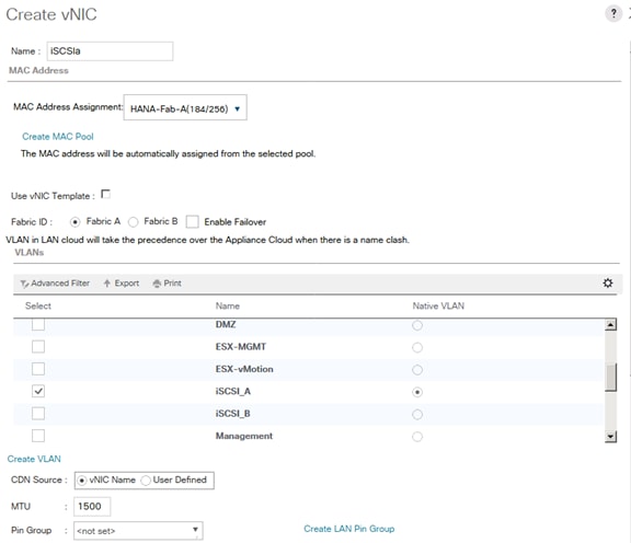
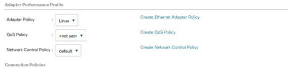
Figure 21 Create iSCSI B Same VLAN as iSCSIa
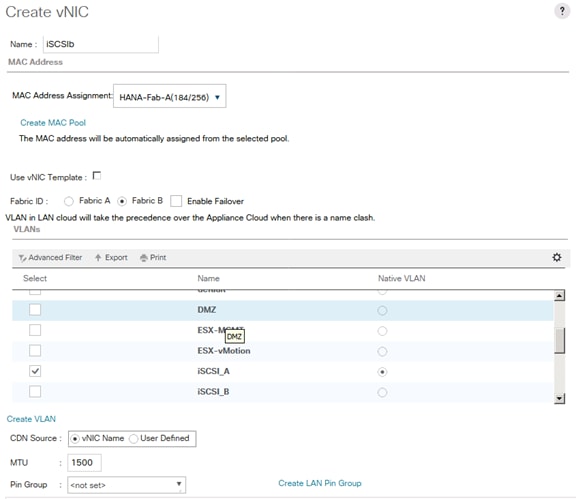
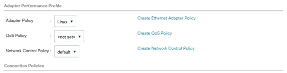
9. Click +iSCSI vNICs.
10. Click Create IQN Suffix Pool.
Figure 22 Create the suffix pool
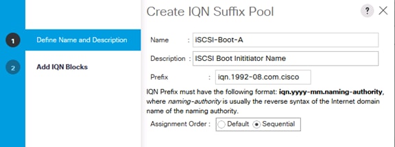
Figure 23 create the block
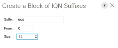
Figure 24 Result
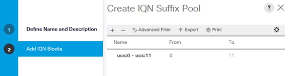
11. Select the Initiator Name Assignment for this profile.
12. Click add iSCSI initiator interfaces.
Figure 25 Add iSCSI vNICa
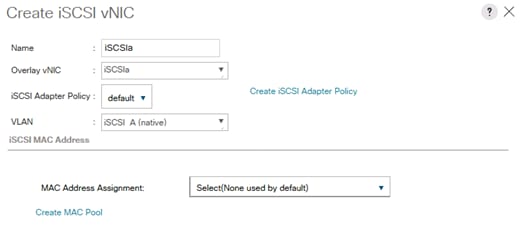
Figure 26 add iSCSIvNICb
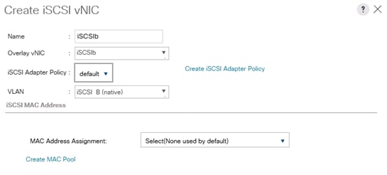
13. Click Next to configure the SAN.
14. Select no vHBA.
15. Click Next.
16. No Zoning in this environment.
17. Configure the vNIC Placement.
Figure 27 vCon 1 and 2
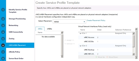
Figure 28 vCon 3 and 4
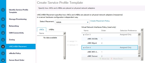
1. Do not create a vMedia Policy, click Next.
2. Server Boot Order.
3. Create a new iSCSI boot order:
a. Add a local DVD.
b. Add the iSCSI NICs (add iSCSI Boot).
c. Add iSCSIa.
d. Add iSCSIb.
Figure 29 Create a iSCSI Boot Policy
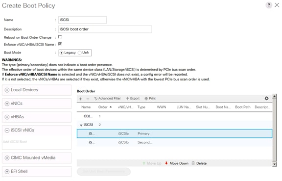
Figure 30 Select the New iSCSI Boot Profile and Set iSCSI Boot Parameter
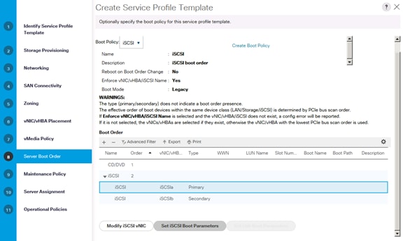
4. First Target add the NetApp iSCSI target in this case it is iqn.1992-08.com.netapp:sn.35084cc1105511e7983400a098aa4cc7:vs.4
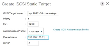
Figure 31 Second Target
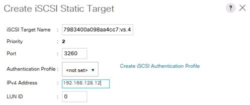
5. Click OK.
6. Select default Maintenance Policy.
7. Server Assignment select Assign-Later and HANA-FW firmware Policy.
8. Select Operational Policies.
Figure 32 Server Policies -1
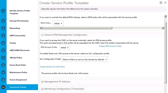
Figure 33 Server Policies 2
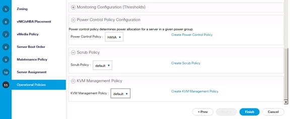
9. Click Finish to complete the Service Profile generation.
Create Service Profile from the Template
To create service profiles from the service profile template, complete the following steps:
1. In Cisco UCS Manager, click the Servers tab in the navigation pane.
2. Select Service Profile Templates > root > Sub-Organization > HANA > Service Template HANA-B260.
3. Right-click Service Template HANA-B260 and select Create Service Profiles from Template.
4. Enter Server0 as the service profile prefix.
5. Enter 1 as 'Name Suffix Starting Number'.
6. Enter 12 as the 'Number of Instances'.
7. Click OK to create the service profile.
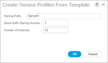
![]() As soon as the specified number of Service Profiles are created, profiles will associate with a blade if physically available.
As soon as the specified number of Service Profiles are created, profiles will associate with a blade if physically available.
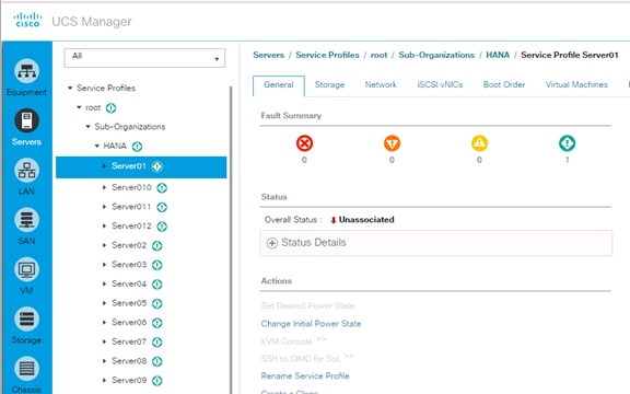
8. Assign the Service Profile to a server:
a. In Cisco UCS Manager, click the Equipment tab in the navigation pane.
b. Select Equipment > Chassis > Chassis 1 > Server 1.
c. Right-click on Server 1 and select Associate Service Profile.
d. Select service profile Server01 and associate the profile to the server.
9. Click OK to associate the profile.
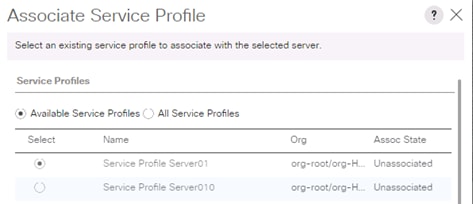
![]() The configuration will start immediately after acknowledge the reboot.
The configuration will start immediately after acknowledge the reboot.
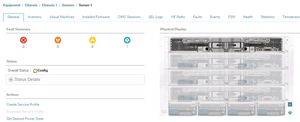
Create Service Profile Templates Bare Metal SAP HANA Scale-Up
To create the service profile template for SAP HANA Scale-Up, complete the following steps:
1. In Cisco UCS Manager, click the Servers tab in the navigation pane.
2. Select Service Profile Templates > root > Sub-Organization > HANA.
3. Right-click HANA.
4. Select Create Service Profile Template to open the Create Service Profile Template wizard.
5. Identify the service profile template:
a. Enter HANA-Scale-UP as the name of the service profile template.
b. Select the Updating Template option.
c. Under UUID, select HANA-UUID as the UUID pool.
d. Click Next.
6. Configure the networking options:
a. Keep the default setting for Dynamic vNIC Connection Policy.
b. Select the Expert option to configure the LAN connectivity.
c. Click the upper Add button to add a vNIC to the template.
d. In the Create vNIC dialog box, enter HANA-Boot as the name of the vNIC.
e. Select the Use vNIC Template checkbox.
f. In the vNIC Template list, select HANA-Boot
g. In the Adapter Policy list, select Linux-B460.
h. Click OK to add this vNIC to the template.
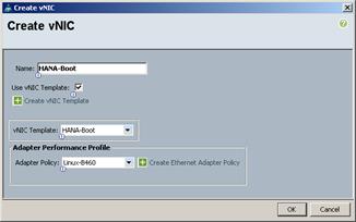
i. Repeat steps c-h for each vNIC.
j. Add vNIC for HANA-Storage.
k. Add vNIC for HANA-Client.
l. Add vNIC for HANA-AppServer.
m. Add vNIC for HANA-DataSource.
n. Add vNIC for HANA-Replication.
o. Add vNIC for HANA-Backup.
p. Add vNIC for HANA-Admin.
q. Review the table in the Networking page to make sure that all vNICs were created.
r. Click Next.
![]() Even though eight Networks were defined, they are optional and if they are not needed in your deployment, the addition of a vNIC template for an optional network is not required.
Even though eight Networks were defined, they are optional and if they are not needed in your deployment, the addition of a vNIC template for an optional network is not required.
7. Configure the storage options:
a. No change is required for a local disk configuration policy.
b. Select the No vHBAs option for the “How would you like to configure SAN connectivity?” field.
c. Click Next.
8. Set no Zoning options and click Next.
9. Set the vNIC/vHBA placement options.
10. For Cisco UCS B200 M4 Server / Cisco UCS C240 M4 Server / Cisco UCS B240 M4 Server with one VIC cards:
a. In the “Select Placement” list, select the Specify Manually.
b. Select vCon1 and assign the vNICs to the virtual network interfaces policy in the following order:
i. HANA-Boot
ii. HANA-Client
iii. HANA-Storage
iv. HANA-Backup
v. HANA-AppServer
vi. HANA-DataSource
vii. HANA-Replication
viii. HANA-Admin
c. Review the table to verify that all vNICs were assigned to the policy in the appropriate order.
d. Click Next.
11. For Cisco UCS B260 M4 / Cisco UCS B460 M4 Servers with two VIC cards:
a. In the “Select Placement” list, select the HANA-B260 placement policy.
b. Select vCon1 and assign the vNICs to the virtual network interfaces policy in the following order:
i. HANA-Boot
ii. HANA-Client
iii. HANA-DataSource
iv. HANA-Replication
c. Select vCon2 and assign the vNICs to the virtual network interfaces policy in the following order:
i. HANA-Storage
ii. HANA-Backup
iii. HANA-AppServer
iv. HANA-Admin
d. Review the table to verify that all vNICs were assigned to the policy in the appropriate order.
e. Click Next.
12. For Cisco UCS B460 M4 Servers with four VIC cards:
a. In the “Select Placement” list, select the HANA-B460 placement policy.
b. Select vCon1 and assign the vNICs to the virtual network interfaces policy in the following order:
i. HANA-Boot
ii. HANA-Client
c. Select vCon2 and assign the vNICs to the virtual network interfaces policy in the following order:
i. HANA-Storage
ii. HANA-AppServer
d. Select vCon3 and assign the vNICs to the virtual network interfaces policy in the following order:
i. HANA-DataSource
ii. HANA-Replication
e. Select vCon4 and assign the vNICs to the virtual network interfaces policy in the following order:
i. HANA-Backup
ii. HANA-Admin
f. Review the table to verify that all vNICs were assigned to the policy in the appropriate order and click Next.
13. No Change required on the vMedia Policy, click Next.
14. Set the server boot order: Select PXE-Boot for Boot Policy.
15. 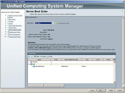
16. Click Next.
17. Add a maintenance policy:
a. Select the default Maintenance Policy.
b. Click Next.
18. Specify the server assignment:
a. In the Pool Assignment list, select the appropriated pool created for scale-up servers.
b. Optional: Select a Server Pool Qualification policy.
c. Select Down as the power state to be applied when the profile is associated with the server.
d. Expand Firmware Management at the bottom of the page and select HANA-FW from the Host Firmware list.
e. Click Next.
19. Add operational policies:
a. In the BIOS Policy list, select HANA-BIOS.
b. Leave External IPMI Management Configuration as <not set> in the IPMI Access Profile. Select SoL-Console in the SoL Configuration Profile.
c. Expand Management IP Address, in the Outband IPv4 tap choose ext-mgmt in the Management IP Address Policy.
d. Expand Power Control Policy Configuration and select No-Power-Cap in the Power Control Policy list.
20. Click Finish to create the service profile template.
21. Click OK in the confirmation message.
Create Service Profiles
To create service profiles from the service profile template, complete the following steps:
1. In Cisco UCS Manager, click the Servers tab in the navigation pane.
2. Select Service Profile Templates > root > Sub-Organization > HANA > Service Template HANA-Scale-UP.
3. Right-click HANA-Scale-UP and select Create Service Profiles from Template.
4. Enter appropriate name for the service profile prefix.
5. Enter 1 as 'Name Suffix Starting Number'.
6. Enter appropriate number of service profile to be created in the 'Number of Instances'.
7. Click OK to create the service profile.
Service Profile for Virtualized SAP HANA (vHANA) Hosts
The Service Profile is created for virtualized SAP HANA which can be used for Cisco UCS B200 M4 Server, Cisco UCS B260 M4 Server, Cisco UCS C220 M4 Server, Cisco UCS C240 M4 Server, Cisco UCS C460 M4 Server and Cisco UCS B460 M4 Server with iSCSI boot for ESXi.
![]() The Service Profiles created for vHANA can be used for a virtualized environment for SAP Application Servers.
The Service Profiles created for vHANA can be used for a virtualized environment for SAP Application Servers.
(Optional) Create New Organization
To create an organization unit, complete the following steps:
1. In Cisco UCS Manager, on the Tool bar click New.
2. From the drop-down menu select Create Organization.
3. Enter the Name as vHANA.
4. Optional Enter the Description as Org for Virtual HANA.
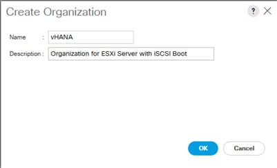
5. Click OK to create the Organization.
Create IQN Pools for iSCSI Boot
To configure the necessary IQN pools for the Cisco UCS environment, complete the following steps.
1. In the Cisco UCS Manager, Select the SAN tab on the left.
2. Select Pools > root > Sub-Organization > vHANA.
3. Right-click IQN Pools under the vHANA sub-organization.
4. Select Add IQN Suffix Pool to create the IQN pool.
5. Enter IQN_Pool for the name of the IQN pool.
6. Optional: Enter a description for the IQN pool.
7. Enter iqn.1992-08.com.cisco as the prefix.
8. Select Sequential for Assignment Order.
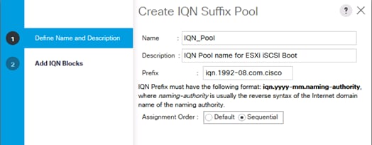
9. Click Next.
10. Click Add.
11. Enter ucs-host as the suffix.
12. Enter 0 in the From field.
13. Specify a size of the IQN block sufficient to support the available server resources.
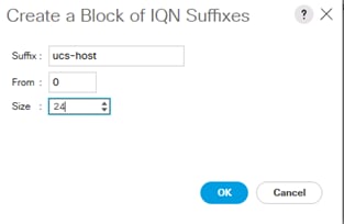
14. Click OK.
15. Click Finish.
16. In the message box that displays, click OK.
Create IP Pools for iSCSI Boot
To configure the necessary IP pools iSCSI boot for the Cisco UCS environment, complete the following steps:
1. In the Cisco UCS Manager, Select the LAN tab on the left.
2. Select Pools > root > Sub-Organization > vHANA
![]() Two IP pools are created, one for each switching fabric.
Two IP pools are created, one for each switching fabric.
3. Right-click IP Pools under the vHANA sub-organization.
4. Select Create IP Pool to create the IP pool.
5. Enter iSCSI_IP_Pool_A for the name of the IP pool.
6. Optional: Enter a description of the IQN pool.
7. Select Sequential for Assignment Order.
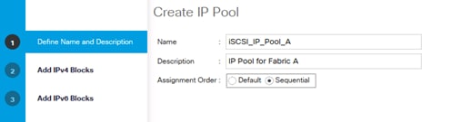
8. Click Next.
9. Click Add.
10. In the From field, enter the beginning of the range to assign as iSCSI IP addresses.
11. Set the size to enough addresses to accommodate the servers.
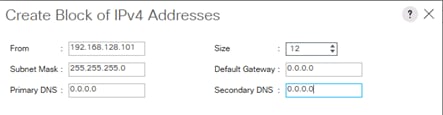
12. Click OK.
13. Click Finish.
14. Right-click IP Pools under the root organization.
15. Select Create IP Pool to create the IP pool.
16. Enter iSCSI_IP_Pool_B for the name of the IP pool.
17. Optional: Enter a description of the IQN pool.
18. Select Sequential for Assignment Order.
19. Click Next.
20. Click Add.
21. In the From field, enter the beginning of the range to assign as iSCSI IP addresses.
22. Set the size to enough addresses to accommodate the servers.
23. Click OK.
24. Click Finish.
Create Additional MAC Pools for the new vHANA Pool
1. In the Cisco UCS Manager, Select the LAN tab on the left.
2. Select Pools > root > Sub-Organization > vHANA
3. Right-click MAC Pools under the vHANA sub-organization.
4. Select Create MAC Pool to create the MAC pool.
5. Enter MAC-Pool-A for the name of the MAC pool.
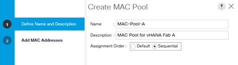
6. Optional: Enter a description of the MAC pool.
7. Select Sequential for Assignment Order.
8. Define the number of MAC addresses for this pool.
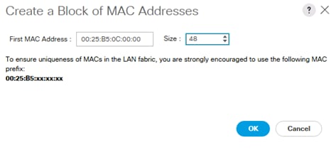
9. Click OK.
10. Click Finish.
11. Repeat this for MAC Pool Fabric B.
12. In the Cisco UCS Manager, Select the LAN tab on the left.
13. Select Pools > root > Sub-Organization > vHANA
14. Right-click MAC Pools under the vHANA sub-organization.
15. Select Create MAC Pool to create the MAC pool.
16. Enter MAC-Pool-B for the name of the MAC pool.
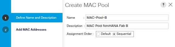
17. Optional: Enter a description of the MAC pool.
18. Select Sequential for Assignment Order.
19. Define the number of MAC addresses for this pool
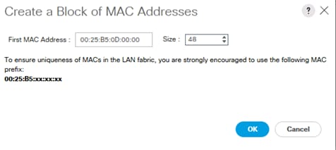
20. Click OK.
21. Click Finish.
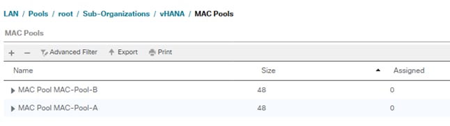
Create Additional VLANs
To configure the necessary VLANs for the virtualized environment, complete the following steps:
1. In Cisco UCS Manager, click the LAN tab in the navigation pane.
![]() In this procedure, eight VLANs are created.
In this procedure, eight VLANs are created.
2. Select LAN > LAN Cloud.
3. Right-click VLANs.
4. Select Create VLANs (Figure 131).
5. Enter ESX-MGMT as the name of the VLAN to be used for management traffic.
6. Keep the Common/Global option selected for the scope of the VLAN.
7. Enter <<var_vhana_esx_mgmt_vlan_id>> as the ID of the management VLAN.
8. Keep the Sharing Type as None.
9. Click OK and then click OK again.
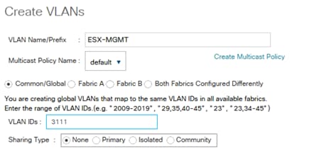
10. Right-click VLANs.
11. Select Create VLANs.
12. Enter ESX-vMotion as the name of the VLAN to be used for vMotion.
13. Keep the Common/Global option selected for the scope of the VLAN.
14. Enter the <<var_vhana_esx_vmotion_vlan_id>> as the ID of the vMotion VLAN.
15. Keep the Sharing Type as None.
16. Click OK and then click OK again.
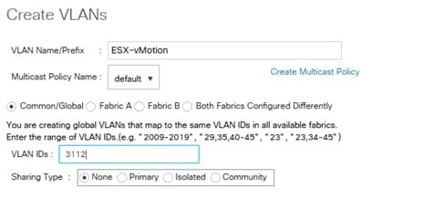
Create VLAN Group for vHANA
1. In Cisco UCS Manager, click the LAN tab in the navigation pane.
2. Select LAN > LAN Cloud.
3. Right-click VLAN Groups.
4. Select Create VLAN Groups
5. Enter vHANA-Zone as the name of the VLAN Group.
6. Select ESX-MGMT,ESX-vMotion, ESX-NFS, vHANA-Access, vHANA-Storage, iSCSI-A and iSCSI-B.
7. Click Next.
8. Click Next on Add Uplink Ports.
9. Choose Port-Channels Create for vHANA vPC-31-vHANA and vPC-32-vHANA.
10. Click Finish.
Create vNIC Templates
To create multiple virtual network interface card (vNIC) templates for the Cisco UCS environment, complete the following steps:
1. In Cisco UCS Manager, click the LAN tab in the navigation pane.
2. Select Policies > root > Sub-Organization > vHANA.
3. Right-click vNIC Templates.
4. Select Create vNIC Template.
5. Enter ESX_Mgmt_A as the vNIC template name.
6. Keep Fabric A selected.
7. Do not select the Enable Failover checkbox.
8. Under Target, make sure that the VM checkbox is not selected.
9. Select Updating Template as the Template Type.
10. Under VLANs, select the checkboxes for NFS, ESX-MGMT, ESX-vMotion
11. For MTU, enter 9000.
12. In the MAC Pool list, select MAC_Pool_A.
13. Click OK to create the vNIC template.
14. Click OK.
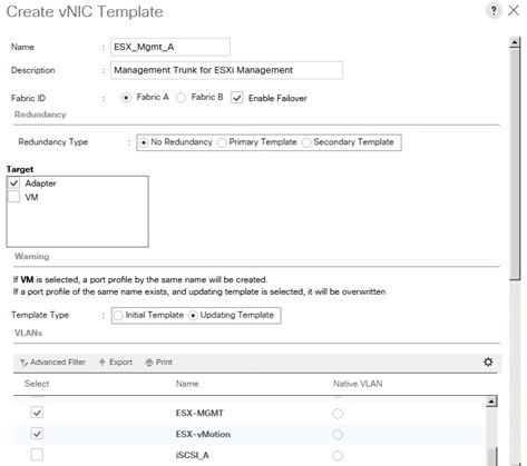
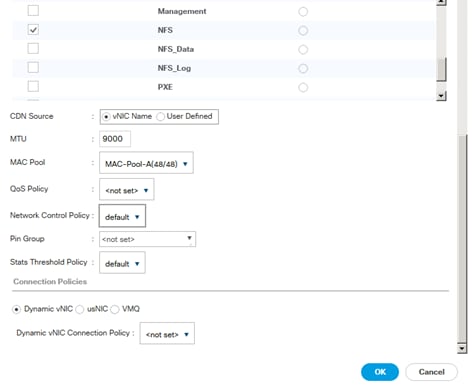
15. In the navigation pane, select the LAN tab.
16. Select Policies > root.
17. Right-click vNIC Templates.
18. Select Create vNIC Template.
19. Enter ESX_Mgmt_A as the vNIC template name.
20. Select Fabric B.
21. Do not select the Enable Failover checkbox.
22. Under Target, make sure the VM checkbox is not selected.
23. Select Updating Template as the template type.
24. Under VLANs, select the checkboxes for NFS, ESX-MGMT,ESX-vMotion.
25. For MTU, enter 9000.
26. In the MAC Pool list, select MAC_Pool_B.
27. Click OK to create the vNIC template.
28. Click OK.
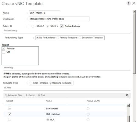
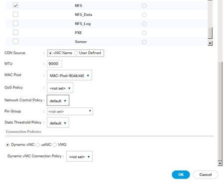
29. Select the LAN tab on the left.
30. Select Policies > root.
31. Right-click vNIC Templates.
32. Select Create vNIC Template.
33. Enter iSCSI_A as the vNIC template name.
34. Leave Fabric A selected.
35. Do not select the Enable Failover checkbox.
36. Under Target, make sure that the VM checkbox is not selected.
37. Select Updating Template for Template Type.
38. Under VLANs, select iSCSI-A-VLAN. Set iSCSI-A-VLAN as the native VLAN.
39. Under MTU, enter 9000.
40. From the MAC Pool list, select MAC_Pool_A.
41. Click OK to complete creating the vNIC template.
42. Click OK.
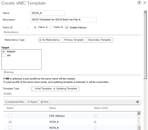
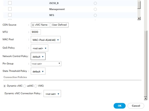
43. Select the LAN tab on the left.
44. Select Policies > root.
45. Right-click vNIC Templates.
46. Select Create vNIC Template.
47. Enter iSCSI_Template_B as the vNIC template name.
48. Select Fabric B.
49. Do not select the Enable Failover checkbox.
50. Under Target, make sure that the VM checkbox is not selected.
51. Select Updating Template for Template Type.
52. Under VLANs, select iSCSI-B-VLAN. Set iSCSI-B-VLAN as the native VLAN.
53. Under MTU, enter 1500.
54. From the MAC Pool list, select MAC_Pool_B.
55. Click OK to complete creating the vNIC template.
56. Click OK.
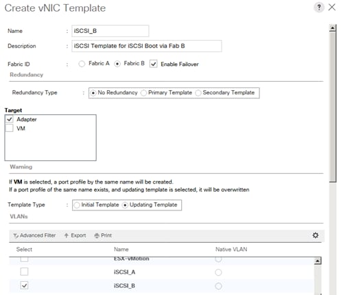
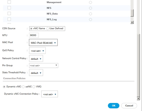
![]() Additional vNIC templates are created for each vHANA system to separate the traffic between ESX management and vHANA VMs. These vNICs are used for vHANA system storage access, client access and access for application server.
Additional vNIC templates are created for each vHANA system to separate the traffic between ESX management and vHANA VMs. These vNICs are used for vHANA system storage access, client access and access for application server.
To create additional vNIC templates, complete the following steps:
1. In Cisco UCS Manager, click the LAN tab in the navigation pane.
2. Select Policies > root > Sub-Organization > vHANA
3. Right-click vNIC Templates.
4. Select Create vNIC Template.
5. Enter vHANA_A as the vNIC template name.
6. Keep Fabric A selected.
7. Do not select the Enable Failover checkbox.
8. Under Target, make sure that the VM checkbox is not selected.
9. Select Updating Template as the Template Type.
10. Under VLANs, select the checkboxes for Access, Backup, Application and vHANA-Access.
11. For MTU, enter 9000.
12. In the MAC Pool list, select MAC_Pool_A.
13. Click OK to create the vNIC template.
14. Click OK.
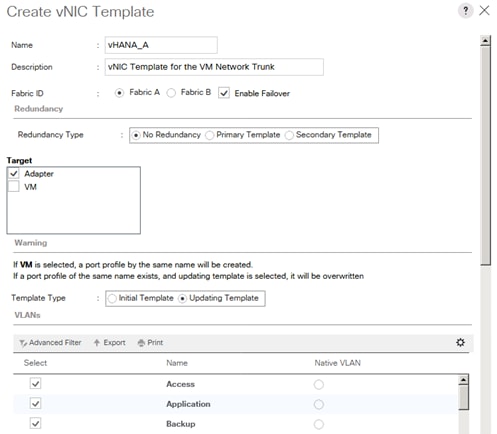
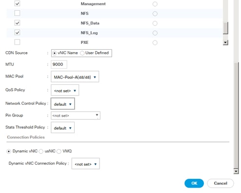
15. In the navigation pane, select the LAN tab.
16. Select Policies > root.
17. Right-click vNIC Templates.
18. Select Create vNIC Template.
19. Enter vNIC_vHANA2_B as the vNIC template name.
20. Select Fabric B.
21. Do not select the Enable Failover checkbox.
22. Under Target, make sure the VM checkbox is not selected.
23. Select Updating Template as the template type.
24. Under VLANs, select the checkboxes for vHANA-Storage and vHANA-Access
25. For MTU, enter 9000.
26. In the MAC Pool list, select MAC_Pool_B.
27. Click OK to create the vNIC template.
28. Click OK.
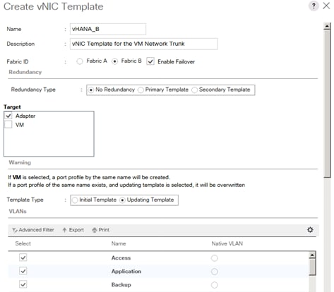
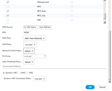
29.
The result after this step should look like the screenshot below:
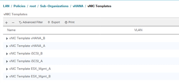
Create Boot Policies
This procedure applies to a Cisco UCS environment in which two iSCSI logical interfaces (LIFs) are on cluster node 1 (iscsi_lif01a, iscsi_lif01b) and two iSCSI LIFs are on cluster node 2 (iscsi_lif02a, iscsi_lif02b).
A300-HANA::> network interface show -vserver Infra-SVM
Logical Status Network Current Current Is
Vserver Interface Admin/Oper Address/Mask Node Port Home
----------- ---------- ---------- ------------------ ------------- ------- ----
Infra-SVM
PXE-01 up/up 192.168.127.11/24 A300-HANA-01 a0a-127 true
PXE-02 up/up 192.168.127.12/24 A300-HANA-02 a0a-127 true
infra-svm-mgmt
up/up 192.168.76.17/24 A300-HANA-02 e0c true
iscsi_lif01a up/up 192.168.128.11/24 A300-HANA-01 a0a-128 true
iscsi_lif01b up/up 192.168.129.11/24 A300-HANA-01 a0a-129 true
iscsi_lif02a up/up 192.168.128.12/24 A300-HANA-02 a0a-128 true
iscsi_lif02b up/up 192.168.129.12/24 A300-HANA-02 a0a-129 true
nfs_lif01 up/up 192.168.130.11/24 A300-HANA-01 a0a-130 true
nfs_lif02 up/up 192.168.130.12/24 A300-HANA-02 a0a-130 true
9 entries were displayed.
![]() One boot policy is configured in this procedure. This policy configures the primary target to be iscsi_lif01a.
One boot policy is configured in this procedure. This policy configures the primary target to be iscsi_lif01a.
To create boot policies for the Cisco UCS environment, complete the following steps:
1. In Cisco UCS Manager, click the Servers tab in the navigation pane.
2. Select Policies > root > Sub-Organization > vHANA.
3. Right-click Boot Policies.
4. Select Create Boot Policy.
5. Enter Boot-Fabric-A as the name of the boot policy.
6. Optional: Enter a description for the boot policy.
7. Keep the Reboot on Boot Order Change option cleared.
8. Expand the Local Devices drop-down menu and select Add CD-ROM.
9. Expand the iSCSI vNICs section and select Add iSCSI Boot.
10. In the Add iSCSI Boot dialog box, enter iSCSI-A. (This Interface will be created in the next section)
11. Click OK.
12. Select Add iSCSI Boot.
13. In the Add iSCSI Boot dialog box, enter iSCSI-B.
14. Click OK.
15. Click OK to save the boot policy. Click OK to close the Boot Policy window.
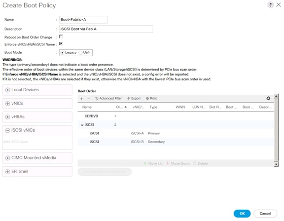
Create BIOS Policies
To create a server BIOS policy for the Cisco UCS environment, complete the following steps:
1. In Cisco UCS Manager, click the Servers tab in the navigation pane.
2. Select Policies > root > Sub-Organization > vHANA.
3. Right-click BIOS Policies.
4. Select Create BIOS Policy.
5. Enter vHANA-Host as the BIOS policy name.
6. Change the Quiet Boot setting to Disabled.
7. Click Next.
8. Select Hyper Threading enabled.
9. Select Virtualization Technology (VT) enabled.
10. Click Finish to create the BIOS policy.
Create Service Profile Templates
To create the service profile template, complete the following steps:
1. In Cisco UCS Manager, click the Servers tab in the navigation pane.
2. Select Service Profile Templates > root > Sub-Organization > vHANA.
3. Right-click vHANA.
4. Select Create Service Profile Template to open the Create Service Profile Template wizard.
5. Identify the service profile template:
a. Enter vHANA-Host as the name of the service profile template.
b. Select the Updating Template option.
c. Under UUID, select HANA_UUID as the UUID pool.
d. Click Next.
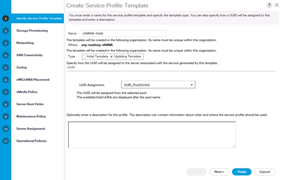
6. Configure the storage options:
a. Select: Specific Storage Profile
o No Specific Storage Profile
b. Select: Storage Profile Policy
o No Storage Profile
c. Select: Local Disk Configuration Policy
o No-Local
7. If the server in question has local disks, select default in the Local Storage list.
8. If the server in question does not have local disks, select No-Local.
9. Click Next.
10. Configure the networking options:
a. Keep the default setting for Dynamic vNIC Connection Policy.
b. Select the Expert option to configure the LAN connectivity.
c. Click the Add button to add a vNIC to the template.
d. In the Create vNIC dialog box, enter ESX_Mgmt-A as the name of the vNIC.
e. Select the Use vNIC Template checkbox.
f. In the vNIC Template list, select ESX_Mgmt_A.
g. In the Adapter Policy list, select VMWare.
h. Click OK to add this vNIC to the template.
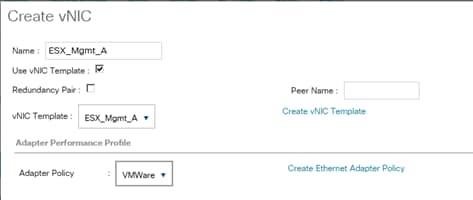
i. On the Networking page of the wizard, click the upper Add button to add another vNIC to the template.
j. In the Create vNIC box, enter ESX_Mgmt_B as the name of the vNIC.
k. Select the Use vNIC Template checkbox.
l. In the vNIC Template list, select ESX_Mgmt_B.
m. In the Adapter Policy list, select VMWare.
n. Click OK to add the vNIC to the template.
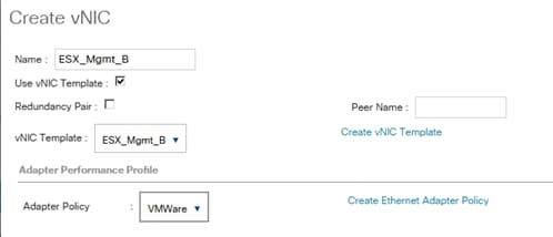
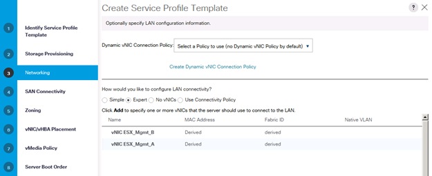
![]() If additional vNIC templates are created to separate the traffic between SAP vHANA VMs, repeat steps 3-14 to add 2 more vNICs
If additional vNIC templates are created to separate the traffic between SAP vHANA VMs, repeat steps 3-14 to add 2 more vNICs
o. Click the upper Add button to add a vNIC to the template.
p. In the Create vNIC dialog box, enter iSCSI-A as the name of the vNIC.
q. Select the Use vNIC Template checkbox.
r. In the vNIC Template list, select iSCSI_A.
s. In the Adapter Policy list, select VMWare.
t. Click OK to add this vNIC to the template.
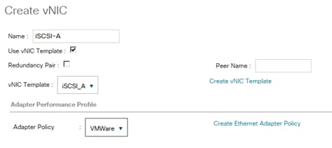
u. Click the upper Add button to add a vNIC to the template.
v. In the Create vNIC dialog box, enter iSCSI-B-vNIC as the name of the vNIC.
w. Select the Use vNIC Template checkbox.
x. In the vNIC Template list, select iSCSI_ B.
y. In the Adapter Policy list, select VMWare.
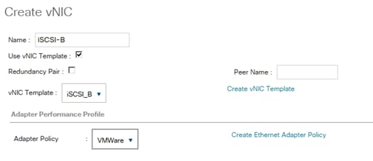
z. Click the Add button to add a vNIC to the template.
aa. In the Create vNIC dialog box, enter vHANA-A as the name of the vNIC.
bb. Select the Use vNIC Template checkbox.
cc. In the vNIC Template list, select vHANA-A.
dd. In the Adapter Policy list, select VMWare.
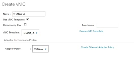
ee. Click the Add button to add a vNIC to the template.
ff. In the Create vNIC dialog box, enter vHANA-B as the name of the vNIC.
gg. Select the Use vNIC Template checkbox.
hh. In the vNIC Template list, select vHANA-B.
ii. In the Adapter Policy list, select VMWare.
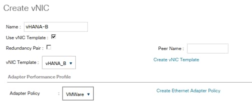
11. Create the iSCSI Overlay NIC Definition:
a. Click the +ISCSI vNICs button in the iSCSI vNIC section to define a vNIC.
b. Select the created IQN_Pool Pool name in Initiator Name Assignment.
c. Click the Add button in the lower section
d. Enter iSCSI-A as the name of the vNIC.
e. Select iSCSI-A for Overlay vNIC.
f. Set the iSCSI Adapter Policy to default.
g. Set the VLAN to iSCSI-A.
h. Leave the MAC Address set to None.
i. Click OK.
j. Expand the “iSCSI vNICs” section.
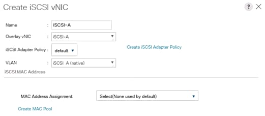
k. Click the Add button in the iSCSI vNIC section to define a vNIC.
l. Enter iSCSI-B as the name of the vNIC.
m. Set the Overlay vNIC to iSCSI-B.
n. Set the iSCSI Adapter Policy to default.
o. Set the VLAN to iSCSI-B.
p. Leave the MAC Address set to None.
q. Click OK.
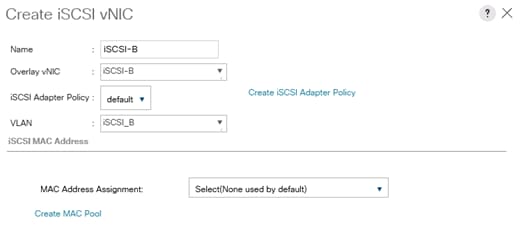
r. Click the +ISCSI vNICs button in the iSCSI vNIC section to define a vNIC.
s. Select the created IQN_Pool Pool name in Initiator Name Assignment.
t. Click the Add button in the lower section
u. Enter iSCSI-A as the name of the vNIC.
v. Select iSCSI-A for Overlay vNIC.
w. Set the iSCSI Adapter Policy to default.
x. Set the VLAN to iSCSI-A.
y. Leave the MAC Address set to None.
z. Click OK.
aa. Expand the “iSCSI vNICs” section.
bb. Click OK.
cc. Review the table in the Networking page to make sure that all vNICs were created.
dd. Click Next.
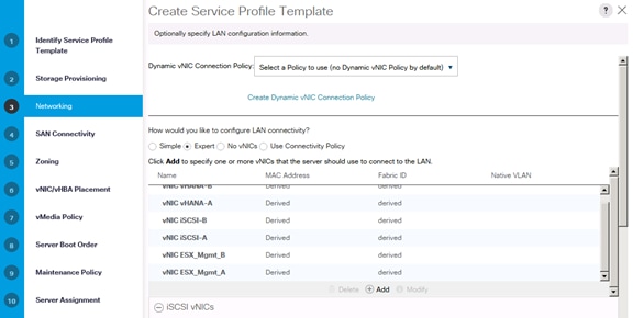
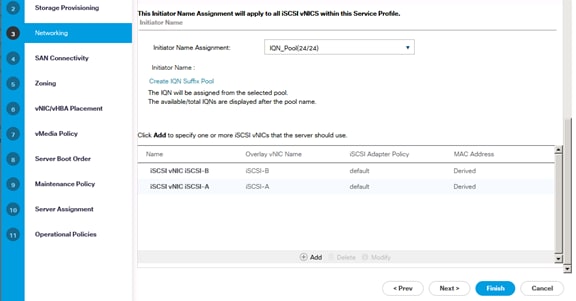
12. SAN Connectivity:
a. Select No vHBA.
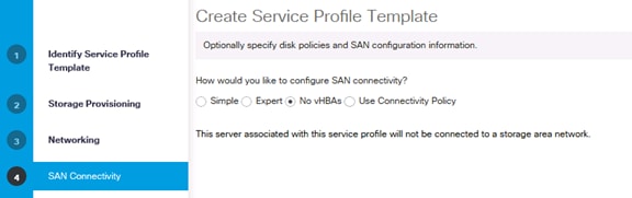
b. Click Next.
13. Set no Zoning options and click Next.
14. Set the vNIC/vHBA placement options.
15. For Cisco UCS B260 M4 Server, Cisco UCS B460 M4 Server and Cisco UCS C460 M4 Server with two or more VIC adapters:
a. In the “Select Placement” list, select the Specify Manually placement policy.
b. Select vCon1 and assign the vHBAs/vNICs to the virtual network interfaces policy in the following order:
i. iSCSI-A
ii. iSCSI-B
iii. vNIC-A
iv. vNIC-B
c. Select vCon2 and assign the vHBAs/vNICs to the virtual network interfaces policy in the following order:
i. vNIC-vHANA2-A
ii. vNIC-vHANA2-B
d. Review the table to verify that all vNICs and vHBAs were assigned to the policy in the appropriate order.
e. Click Next.
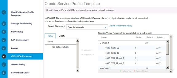

16. For SAP vHANA Hosts Cisco UCS B200 M4 Server, Cisco UCS C220 M4 Server and Cisco UCS C240 M4 Server with single VIC Card:
a. In the “Select Placement” list, select the Specify Manually placement policy.
b. Select vCon1 and assign the vHBAs/vNICs to the virtual network interfaces policy in the following order:
i. iSCSI-vNIC-A
ii. iSCSI-vNIC-B
iii. vNIC-A
iv. vNIC-B
v. vNIC-vHANA2-A
vi. vNIC-vHANA2-B
c. Review the table to verify that all vNICs and vHBAs were assigned to the policy in the appropriate order.
d. Click Next.
17. Click Next on vMedia Policy.
18. Set the server boot order:
a. Log in to the storage cluster management interface and run the following command to capture the iSCSI target IQN name:
A300-HANA::> iscsi nodename -vserver Infra-SVM
Vserver Target Name
---------- -------------------------------------------------------------------
Infra-SVM iqn.1992-08.com.netapp:sn.35084cc1105511e7983400a098aa4cc7:vs.4
A300-HANA::>
b. Copy the Target name with CTRL+C.
c. Select Boot-Fabric-A for Boot Policy.
d. In the Boot Order pane, select iSCSI-A.
e. Click the “Set iSCSI Boot Parameters” button.
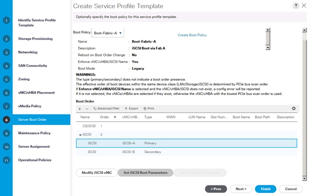
f. Leave the Authentication Profile <not Set>.
g. Set the Initiator Name Assignment to <IQN_Pool>.
h. Set the Initiator IP Address Policy to iSCSI_IP_Pool_A.
i. Keep the “iSCSI Static Target Interface” button selected and click the Add button.
j. Note or copy the iSCSI target name for Infra_SVM.
k. In the Create iSCSI Static Target dialog box, paste the iSCSI target node name.
l. Infra-SVM into the iSCSI Target Name field.
m. Enter the IP address of iSCSI_lif01a for the IPv4 Address field.
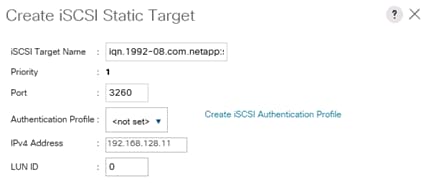
n. Click OK to add the iSCSI static target.
o. Keep the iSCSI Static Target Interface option selected and click the Add button.
p. In the Create iSCSI Static Target window paste the iSCSI target node name from Infra_SVM into the iSCSI Target Name field.
q. Enter the IP address of iscsi_lif02a in the IPv4 Address field.
r. Click OK.

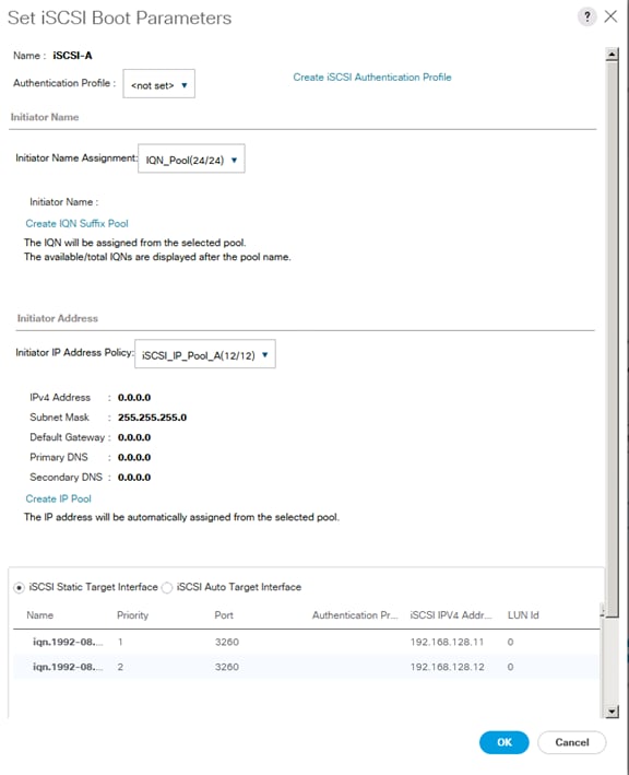
s. Click OK.
t. In the Boot Order pane, select iSCSI-B.
u. Click the Set iSCSI Boot Parameters button.
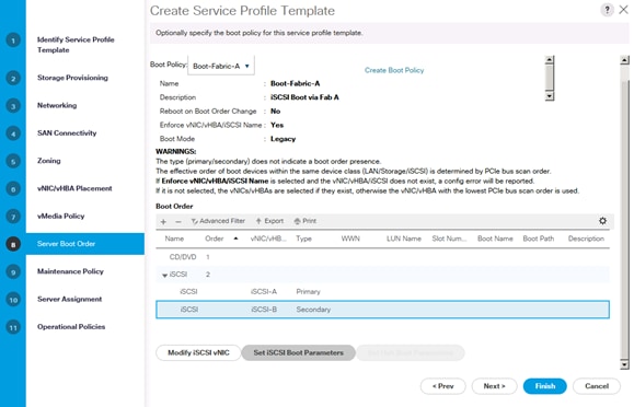
v. In the Set iSCSI Boot Parameters dialog box, set the leave the “Initiator Name Assignment” to <not set>.
w. In the Set iSCSI Boot Parameters dialog box, set the initiator IP address policy to iSCSI_IP_Pool_B.
x. Keep the iSCSI Static Target Interface option selected and click the Add button.
y. In the Create iSCSI Static Target window, paste the iSCSI target node name.
z. Infra-SVM into the iSCSI Target Name field (same target name as above).
aa. Enter the IP address of iscsi_lif01b in the IPv4 address field.
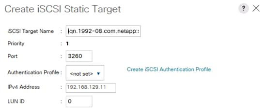
bb. Click OK to add the iSCSI static target.
cc. Keep the iSCSI Static Target Interface option selected and click the Add button.
dd. In the Create iSCSI Static Target dialog box, paste the iSCSI target node name.
ee. Infra-SVM into the iSCSI Target Name field.
ff. Enter the IP address of iscsi_lif02b in the IPv4 Address field.
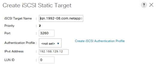
gg. Click OK.
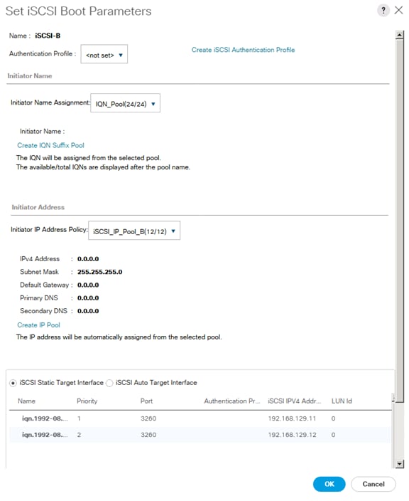
hh. Click OK.
ii. Review the table to make sure that all boot devices were created and identified. Verify that the boot devices are in the correct boot sequence.
jj. Click Next to continue to the next section.
19. Add a maintenance policy:
a. Select the default Maintenance Policy.
b. Click Next.
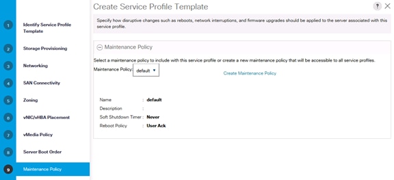
20. Specify the server assignment :
a. In the Pool Assignment list, select an appropriate server pool.
b. Optional: Select a Server Pool Qualification policy.
c. Select Down as the power state to be applied when the profile is associated with the server.
d. Expand Firmware Management at the bottom of the page and select HANA-FW from the Host Firmware list.
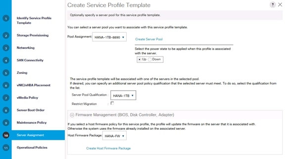
e. Click Next.
21. Add operational policies:
a. In the BIOS Policy list, select vHANA-Host.
b. Expand Power Control Policy Configuration and select No-Power-Cap in the Power Control Policy list.
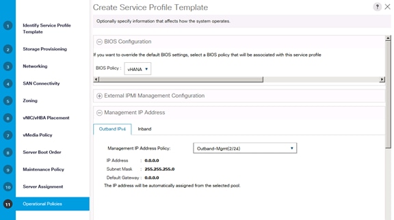
22. Click Finish to create the service profile template.
23. Click OK in the confirmation message.
Create Service Profiles
To create service profiles from the service profile template, complete the following steps:
1. In Cisco UCS Manager, click the Servers tab in the navigation pane.
2. Select Service Profile Templates > root > Sub-Organization > vHANA > Service Template vHANA-Host.
3. Right-click vHANA-Host and select Create Service Profiles from the template.
4. Enter vHANA-0 as the service profile prefix.
5. Enter 1 as 'Name Suffix Starting Number'.
6. Enter 1 as the 'Number of Instances'.
7. Click OK to create the service profile.
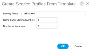
Storage Configuration
Preparation of PXE Boot Environment
Two PXE boot servers are used for a PXE boot to provide redundancy; one on Management Server 01 (ESXi-Mgmt-01) another on Management Server 02 (ESXi-Mgmt-02) for redundancy.
Installing PXE Boot VM on the Management Servers
To build a PXE Boot virtual machine (VM) on the ESXi-Mgmt-01 complete the following steps:
1. Log in to the host by using the VMware vSphere Client.
2. In the VMware vSphere Client, select the host in the inventory pane.
3. Right-click the host and select New Virtual Machine.
4. Select Custom and click Next.
5. Enter a name for the VM, example HANA-Mgmt01, click Next.
6. Select the datastore where the PXE server resides. Click Next.
7. Select Virtual Machine Version: 8. Click Next.
8. Select the Linux option and the SUSE Linux Enterprise 11 (64-bit) version are selected. Click Next.
9. Select two virtual sockets and one core per virtual socket. Click Next.
10. Select 4GB of memory. Click Next.
11. Select three network interface card (NIC).
12. For NIC 1, select the OOB-MGMT Network option and the VMXNET 3 adapter.
13. For NIC 2, select the HANA-Boot Network option and the VMXNET 3 adapter.
14. For NIC 1, select the HANA-Admin Network option and the VMXNET 3 adapter
15. Click Next.
16. Keep the LSI Logic SAS option for the SCSI controller selected. Click Next.
17. Keep the Create a New Virtual Disk option selected. Click Next.
18. Make the disk size at least 60GB. Click Next.
19. Click Next.
20. Select the checkbox for Edit the Virtual Machine Settings Before Completion. Click Continue.
21. Click the Options tab.
22. Select Boot Options.
23. Select the Force BIOS Setup checkbox.
24. Click Finish.
25. From the left pane, expand the host field by clicking the plus sign (+).
26. Right-click the newly created HANA-Mgmt01 and click Open Console.
27. Click the third button (green right arrow) to power on the VM.
28. Click the ninth button (CD with a wrench) to map the SLES-11-SP3-x86_64, and then select Connect to ISO Image on Local Disk.
29. Navigate to the SLES-11 SP3 64 bit ISO, select it, and click Open.
30. Click in the BIOS Setup Utility window and use the right arrow key to navigate to the Boot menu. Use the down arrow key to select CD-ROM Drive. Press the plus (+) key twice to move CD-ROM Drive to the top of the list. Press F10 and Enter to save the selection and exit the BIOS Setup Utility.
31. The SUSE Installer boots. Select the Installation by pressing down arrow key and press Enter.
32. Agree to the License Terms, select Next and press Enter.
33. Skip Media test and click Next.
34. Leave New Installation selected and click Next
35. Select Appropriate Region and Time Zone. Click Next.
36. Under Choose Scenario Keep Physical Machine (also for Fully Virtualized Guests) selected and click Next.
37. In the Overview section, click Software and Choose DHCP and DNS Server Under Primary Functions.
38. Press OK and Accept.
39. Click and Install to perform the installation.
40. After Installation Virtual Machine will reboot.
41. After reboot, the system will continue the installation to customize the installed Operating System.
42. Enter the Password for root User and Confirm Password, then click Next.
43. Enter Hostname and Domain Name, uncheck Change Hostname via DHCP, then click Next.
44. Under Network Configuration, keep Use Following Configuration selected:
a. Under General Network Settings, Support for IPv6 protocol is enabled, click Disable IPv6 on the Warning To apply this change, a reboot is needed Press OK.
b. Under Firewall > Firewall is enabled. Click Disable.
c. Click Network Interfaces. Under the Overview, select the first device and click Edit and enter IP Address <<var_pxe_oob_IP>> and Subnet Mask <<var_pxe_oob_subnet>>. Enter the Hostname, click the General tab and Set MTU 1500 or 9000 depending on the Customer switch config. Click Next.
d. Under Overview, select the second device and click Edit and enter IP Address <<var_pxe_boot_IP>> and Subnet Mask <<var_pxe_boot_subnet>>. Enter the Hostname. Click the General tab and Set MTU 1500, click Next.
e. Under Overview, select the third device and click Edit and enter IP Address <<var_pxe_admin_IP>> and Subnet Mask <<var_pxe_admin_subnet>>. Enter the Hostname. Click the General tab and Set MTU 1500, click Next.
f. Click the Hostname/DNS tab Under Name Server 1, enter the IP address of the DNS Server, optionally enter the IP address for Name Server 2 and Name Server 2. Under Domain Search, enter the Domain name for DNS.
g. Click the Routing tab and Enter the IP address for Default Gateway for Out Band Management IP address, and click OK.
45. Click the VNC Remote Administration and select Allow Remote Administration. Click Finish.
46. Optional; if there is proxy server required for Internet access, click Proxy Configuration, check Enable Proxy. Enter the HTTP Proxy URL, HHTPS Proxy URL, or based on proxy server configuration. Check Use the Same Proxy for All Protocols. If the proxy server requires Authentication, enter the Proxy User Name and Proxy Password and click Finish.
47. Click Next to finish Network Configuration.
48. Under Test Internet Connection, choose No, Skip This Test.
49. For Network Service Configuration, choose default and click Next.
50. For the User Authentication Method, select default Local (/etc/passwd). If there are other options, such as LDAP, NIS, or Windows Domain, configure accordingly.
51. Create New Local User, enter password, and Confirm Password.
52. For Release Notes, click Next.
53. For Use Default Hardware Configuration, click Next.
54. Uncheck Clone This System for AutoYaST and click Finish.
![]() To build a PXE Boot virtual machine (VM) on the Management Server 02, complete the steps above for ESXi-Mgmt-02.
To build a PXE Boot virtual machine (VM) on the Management Server 02, complete the steps above for ESXi-Mgmt-02.
Customize PXE Boot Server
1. Check the IP address are assigned to the PXE boot network:
mgmtsrv01:~ # ip addr sh dev eth0
2: eth0: <BROADCAST,MULTICAST,UP,LOWER_UP> mtu 1500 qdisc mq state UP qlen 1000
link/ether 00:0c:29:9c:63:bf brd ff:ff:ff:ff:ff:ff
inet 192.168.127.6/24 brd 192.168.127.255 scope global eth0
eth1 Link encap:Ethernet HWaddr 00:0C:29:3D:3F:62
inet addr:192.168.127.27 Bcast:192.168.127.255 Mask:255.255.255.0
UP BROADCAST RUNNING MULTICAST MTU:1500 Metric:1
RX packets:15 errors:0 dropped:0 overruns:0 frame:0
TX packets:0 errors:0 dropped:0 overruns:0 carrier:0
collisions:0 txqueuelen:1000
RX bytes:5124 (5.0 Kb) TX bytes:0 (0.0 b)
eth2 Link encap:Ethernet HWaddr 00:0C:29:3D:3F:6C
inet addr:172.29.112.27 Bcast:172.29.112.255 Mask:255.255.255.0
UP BROADCAST RUNNING MULTICAST MTU:1500 Metric:1
RX packets:2 errors:0 dropped:0 overruns:0 frame:0
TX packets:0 errors:0 dropped:0 overruns:0 carrier:0
collisions:0 txqueuelen:1000
RX bytes:120 (120.0 b) TX bytes:0 (0.0 b)
Configure the NTP Server
vi /etc/ntp.conf
server <<var_global_ntp_server_ip>>
Configure the /etc/hosts File of the Management Stations
cat /etc/hosts
#
# hosts This file describes a number of hostname-to-address
# mappings for the TCP/IP subsystem. It is mostly
# used at boot time, when no name servers are running.
# On small systems, this file can be used instead of a
# "named" name server.
# Syntax:
#
# IP-Address Full-Qualified-Hostname Short-Hostname
#
127.0.0.1 localhost
172.25.186.27 mgmtsrv01.ciscolab.local mgmtsrv01
## PXE VLAN
192.168.127.11 nfspxe
192.168.127.6 mgmtsrv01p
192.168.127.101 server01p
192.168.127.102 server02p
192.168.127.103 server03p
192.168.127.104 server04p
192.168.127.105 server05p
192.168.127.106 server06p
Mount Volume for PXE Boot Configuration
1. To mount the tftpboot, software and osmaster volumes, add the entry to /etc/fstab with the values listed below:
vi /etc/fstab
nfspxe:/tftpboot /tftpboot nfs defaults 0 0
nfspxe:/software /NFS/software nfs defaults 0 0
nfspxe:/suse_os_master /NFS/osmaster nfs defaults 0 0
2. Create the directories for mount points:
mkdir /tftpboot
mkdir /NFS
mkdir /NFS/osmaster
mkdir /NFS/software
3. Mount the nfs file system:
mount /NFS/osmaster
mount /tftpboot
mount /NFS/software
Download the SUSE ISO
1. Download the SUSE Linux Enterprise for SAP Applications 11 SP3 ISO from https://www.suse.com/
2. Upload ISO downloaded to /NFS/software directory using scp tool.
Update PXE Boot VM
To update the SUSE virtual machine to latest patch level, complete the following steps:
![]() This document assumes that a SUSE License key is obtained and registered username and password is available. VM has internet access.
This document assumes that a SUSE License key is obtained and registered username and password is available. VM has internet access.
1. ssh to the PXE boot VM.
2. Login as root and password.
3. Execute the below command to Register the SUSE.
suse_register -i -r -n -a email= <<email_address>> -a regcode-sles=<<registration_code>>
After the registration, all the repositories are updated as shown below:
All services have been refreshed.
All repositories have been refreshed.
Refreshing service 'nu_novell_com'.
Adding repository 'SLES12-SP2Updates' [done]
Adding repository 'SLES11-Extras' [done]
Adding repository 'SLES11-SP1-Pool' [done]
Adding repository 'SLES12-SP1Updates' [done]
Adding repository 'SLES12-SP2Pool' [done]
Adding repository 'SLES12-SP1Extension-Store' [done]
Adding repository 'SLE12-SP2Debuginfo-Pool' [done]
Adding repository 'SLES12-SP1Core' [done]
Adding repository 'SLE11-SP1-Debuginfo-Updates' [done]
Adding repository 'SLES11-SP1-Updates' [done]
Adding repository 'SLES12-SP2Extension-Store' [done]
Adding repository 'SLE12-SP2Debuginfo-Updates' [done]
Adding repository 'SLE11-Security-Module' [done]
Adding repository 'SLE12-SP2Debuginfo-Core' [done]
Adding repository 'SLE12-SP2Debuginfo-Updates' [done]
All services have been refreshed.
Retrieving repository 'SLES12-SP2Pool' metadata [done]
Building repository 'SLES12-SP2Pool' cache [done]
Retrieving repository 'SLES12-SP2Updates' metadata [done]
Building repository 'SLES12-SP2Updates' cache [done]
All repositories have been refreshed.
Registration finished successfully
4. Execute the below command to update the server:
zypper update
5. Follow the on-screen instruction to complete the update process.
6. Reboot the server
Initial PXE Configuration
To configure a PXE (Pre-boot Execution Environment) boot server, two packages, the DHCP (Dynamic Host Configuration Protocol) server and tftp server are required. DHCP server is already installed in the previous step.
To install and configure tftp server, complete the following steps:
1. Configure the tftp server.
2. Log in to the VM created PXE boot Server using SSH.
3. Search the package tftp server using command shown below:
HANA-mgmtsrv01:~ # zypper se tftp
Loading repository data...
Reading installed packages...
S | Name | Summary | Type
--+-------------------+---------------------------------------+-----------
| atftp | Advanced TFTP Server and Client | package
| atftp | Advanced TFTP Server and Client | srcpackage
| tftp | Trivial File Transfer Protocol (TFTP) | package
| tftp | Trivial File Transfer Protocol (TFTP) | srcpackage
i | yast2-tftp-server | Configuration of TFTP server | package
| yast2-tftp-server | Configuration of TFTP server | srcpackage
4. Install the tftp server:
HANA-mgmtsrv01:~ # zypper in tftp
Loading repository data...
Reading installed packages...
Resolving package dependencies...
The following NEW package is going to be installed:
tftp
1 new package to install.
Overall download size: 42.0 KiB. After the operation, additional 81.0 KiB will
be used.
Continue? [y/n/?] (y): y
Retrieving package tftp-0.48-101.31.27.x86_64 (1/1), 42.0 KiB (81.0 KiB unpacked)
Installing: tftp-0.48-101.31.27 [done]
5. Configure xinetd to respond to tftp requests:
# default: off
# description: tftp service is provided primarily for booting or when a \
# router need an upgrade. Most sites run this only on machines acting as
# "boot servers".
service tftp
{
socket_type = dgram
protocol = udp
wait = yes
flags = IPv6 IPv4
user = root
server = /usr/sbin/in.tftpd
server_args = -s /tftpboot
}
6. To configure your TFTP server, create a directory which will be the base directory for the Linux boot images and the PXE boot server configuration files:
mkdir /tftpboot
chmod 755 tftpboot
7. To make sure the TFTP servers can startup on subsequent reboots, execute the following command:
chkconfig xinetd on
chkconfig tftp on
rcxinetd restart
Shutting down xinetd: (waiting for all children to terminate) done
Starting INET services. (xinetd) done
8. Make sure syslinux is installed:
rpm -qa syslinux
syslinux-3.82-8.10.23
9. Copy the pxelinux image on to the root directory of the tftp server:
cp /usr/share/syslinux/pxelinux.0 /tftpboot/
10. PXELinux relies on the pxelinux.cfg directory to be in the root of the tftp directory for configuration.
mkdir /tftpboot/pxelinux.cfg
Configuration of the DHCP Server for PXE Boot
1. Activate the DHCP server to listen on eth1, which is configured for PXE boot VLAN 127:
vi /etc/sysconfig/dhcpd
#
DHCPD_INTERFACE="eth1"
2. Obtain the MAC Address List for HANA-Boot vNIC for service Profiles created. A separate MAC address pool was created for HANA-Boot and assigned in the sequential order. To obtain the MAC address for HANA-Boot, complete the following steps:
a. Log in to Cisco UCS Manager; click the LAN tab in the navigation pane.
b. Select Pools > root > MAC pools > MAC Pool HANA-Boot.
c. Expand MAC Pool HANA-Boot.
d. Click the MAC Addresses tab on the right pane.
3. 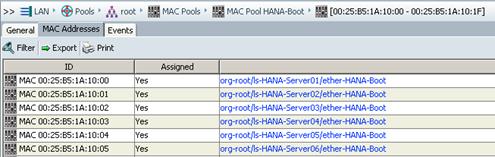
![]() The MAC address is assigned to the Service Profile in sequential order.
The MAC address is assigned to the Service Profile in sequential order.
4. DHCP server requires ‘next-server’ directive to DHCP configuration file; this directive should have the IP address of the TFTP server i.e. (next-server 192.168.127.27;).
5. The second directive that needs to be added to DHCP configuration file is ‘filename’ and it should have the value of ‘pxelinux.0′, for example filename “pxelinux.0”; this will enable PXE booting.
6. To assign hostname to the server via DHCP use the option host-name <<hostname>>.
7. The MAC Address configured for HANA-Boot in the Cisco UCS Service Profile should be reserved with an IP address for each server for PXE boot in the dhcp configuration.
![]() Below is an example of /etc/dhcpd.conf, VLAN ID 127 is used for PXE boot network. The PXE boot server IP address is 192.168.127.27, subnet 255.255.255.0. Assigned IP address for servers are 192.168.127.201-206.
Below is an example of /etc/dhcpd.conf, VLAN ID 127 is used for PXE boot network. The PXE boot server IP address is 192.168.127.27, subnet 255.255.255.0. Assigned IP address for servers are 192.168.127.201-206.
# dhcpd.conf
#
default-lease-time 14400;
ddns-update-style none;
ddns-updates off;
filename "pxelinux.0";
subnet 192.168.127.0 netmask 255.255.255.0 {
group {
next-server 192.168.127.27;
filename "pxelinux.0";
host server01b {
hardware ethernet 00:25:B5:1A:10:00;
fixed-address 192.168.127.201;
option host-name cishana01;
}
host server02b {
hardware ethernet 00:25:B5:1A:10:01;
fixed-address 192.168.127.202;
option host-name cishana02;
}
host server03b {
hardware ethernet 00:25:B5:1A:10:02;
fixed-address 192.168.127.203;
option host-name cishana03;
}
host server04b {
hardware ethernet 00:25:B5:1A:10:03;
fixed-address 192.168.127.204;
option host-name cishana04;
}
host server05b {
hardware ethernet 00:25:B5:1A:10:04;
fixed-address 192.168.127.205;
option host-name cishana05;
}
host server06b {
hardware ethernet 00:25:B5:1A:10:05;
fixed-address 192.168.127.206;
option host-name cishana06;
}
}
}
8. To make sure the DHCP servers can startup on subsequent reboots, execute the following command:
chkconfig dhcpd on
9. Restart the dhcp service for new configuration to take effect:
service dhcpd restart
Shutting down ISC DHCPv4 4.x Server done
Starting ISC DHCPv4 4.x Server [chroot] done
Operating System Installation SUSE SLES12SP2
PXE Boot Preparation for SUSE OS Installation
To use the PXE boot server for OS installation, complete the following steps:
1. Mount the SLES 12 SP2 ISO to temp directory.
mount -o loop /tftpboot/SLE-12-SP2-SAP-x86_64-GM-DVD.iso /mnt
2. Create ISO image repository.
mkdir /NFS/software/SLES/CD
cd /mnt
cp -ar * /NFS/software/SLES/CD/
umount /mnt
3. Create a directory for PXE SUSE installer.
mkdir /tftpboot/suse
4. Copy two files “initrd” and “linux” from SLES 11 SP3 ISO.
cp /NFS/software/SLES/CD/boot/x86_64/loader/linux /tftpboot/suse/linux-iso
cp /NFS/software/SLES/CD/boot/x86_64/loader/initrd /tftpboot/suse/initrd-iso
5. Create a text file that will hold the message which will be displayed to the user when PXE boot server is connected.
vi /tftpboot/boot.msg
<< Enter Your Customise Message for example: Welcome to PXE Boot Environment>>
6. Create a file called: “default” in the directory /tftpboot/pxelinux.cfg with similar syntax to the one shown below:
# UCS PXE Boot Definition
DISPLAY ../boot.msg
DEFAULT Install-SLES4SAP
PROMPT 1
TIMEOUT 50
#
LABEL Install-SLES4SAP
KERNEL suse/linux-iso
APPEND initrd=suse/initrd-iso netsetup=1 install=nfs://192.168.127.11:/software/SLES/CD/?device=eth0
PROMPT: This line allows user to choose a different booting method. The value of one allows the client to choose a different boot method.
DEFAULT: This sets the default boot label.
TIMEOUT: Indicates how long to wait at the “boot:” prompt until booting automatically, in units of 1/10 s.
LABEL: This section defines a label called: “Install-SLES4SAP” so at the boot prompt when ‘Install-SLES4SAP’ is entered, it execute the commands related to the local label. Here Kernel image and initrd images are specified along with ISO location and the Ethernet device to use.
After the PXE configuration is completed, proceed with the Operating System Installation.
![]() For the latest information on SAP HANA installation and OS customization requirement, see the SAP HANA installation guide: http://www.saphana.com/
For the latest information on SAP HANA installation and OS customization requirement, see the SAP HANA installation guide: http://www.saphana.com/
SUSE Linux Enterprise Server
To install the OS based on the PXE Boot Option, complete the following steps:
1. In Cisco UCS Manager, click the Servers tab in the navigation pane.
2. Select Service Profiles > root > HANA-Server01.
3. Click KVM Console.
4. When the KVM Console is launched, click Boot Server.
5. 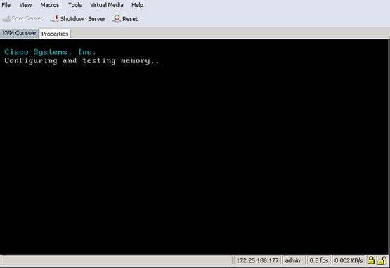
6. If you are using a CD, click Virtual Media > Activate Virtual Devices:
a. Select Accept this Session for Unencrypted Virtual Media Session then click Apply.
b. Click Virtual Media and Choose Map CD/DVD.
c. Click Browse to navigate ISO media location.
d. Click Map Device.
7. For PXE Boot Installation, the “default” file is configured for OS installation. The IP address obtained from DHCP configured on the PXE Boot Server.
8. 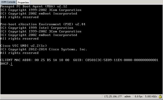
9. Load the Linux and initrd image from PXE server.
10. 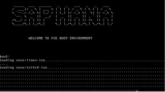
11. The installation process will start from the software directory specified in the “default” file from pxelinux.cfg.
12. 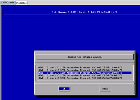
13. Select the interface that is connected to the PXE boot network; for this process it is eth2.
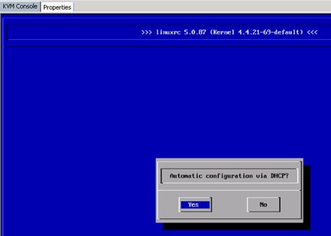
The download of the DVD contend from the NFS share, specified in the PXE boot configuration is shown below:
14. 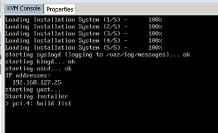
SUSE License agreement is shown below:
15. 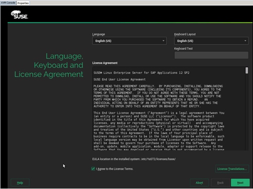
16. Agree to the License Terms, click Next.
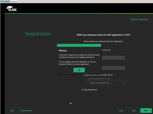
17. Skip the registration and click Next.
18. Select the System Edition.
19. 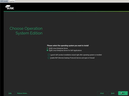
20. Select SLES for SAP and click Next.
![]() Do not install add-ons at this moment.
Do not install add-ons at this moment.
21. 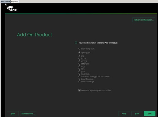
22.
The Disk Partitioner main screen is shown below:
23. 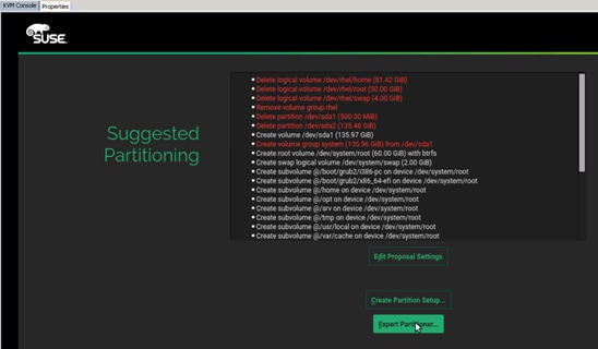
24. Select Expert Partitioner, since you do not have a local disk in the system.
25. Delete all existing partitions.
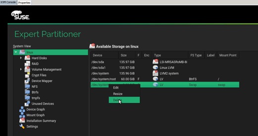
26. After all partitions are deleted select NFS as OS target.
The OS Partitioner for NFS is shown below:
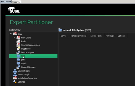
27. On the disk partitioner, select Add.
28. Specify the following:
a. NFS Server (192.168.127.11 – in this case)
b. Remote Directory where the OS will be installed (SLES12SP2/osmaster
c. Mount point (/)
d. Options: rsize=32768,wsize=32768, vers=3,proto=tcp,hard
29. 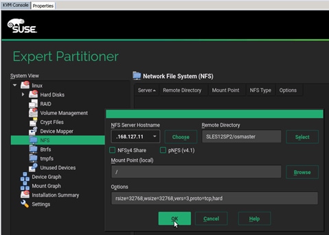
![]() If you do not set the correct mount option, the installation will fail to install some packages.
If you do not set the correct mount option, the installation will fail to install some packages.
30. Click Accept to confirm the location.
31. Click Next.
32. Select the Time Zone.
33. 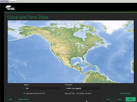
34.
35. Specify the root password.
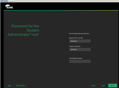
36. Finalize the selection:
a. Disable the Firewall.
b. Default System Target must be Text Mode.
c. Do not import any SSH keys at this moment.
d. Software:
i. Disable Gnome
ii. Select SAP HANA Server Base
iii. (Optional) Select High Availability – (Linux Cluster)
iv. Add single Package:
o OPENipmi
o Ipmitool
o Screen
o Iftop
o (Optional) SAPhanaSR-doc (cluster documentation)
o (Optional) sap_suse_cluster_connector
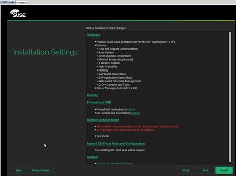
37. Click Install to install the OS.
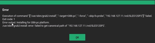
38. Ignore the Grub installation errors since you are installing on NFS, no grub necessary.
39. The system will reboot after the installation.

40. Since Network boot is used, the bootloader will not be installed.
41. Shutdown the System.
To create the initrd image for PXE Boot environment, complete the following steps:
1. Log into PXE Boot server using ssh.
2. Copy the initrd and vmlinux image from the system installed.
![]() Check that the suse_os_master volume is mounted on the /NFS/osmaster
Check that the suse_os_master volume is mounted on the /NFS/osmaster
cd /NFS/osmaster
cp boot/initrd-4.4.21-69-default /tftpboot
cp boot/vmlinuz-4.4.21-69-default /tftpboot
3. Create new PXE Configuration file as described in the section Define the PXE Linux Configuration:
cd /tftpboot/pxelinux.cfg
vi C0A87FC9
# UCS PXE Boot Definition
DISPLAY ../boot.msg
DEFAULT SLES12SP2
PROMPT 1
TIMEOUT 50
#
LABEL SLES12SP2
KERNEL vmlinuz-4.4.21-69-default
APPEND initrd=initrd-4.4.21-69-default rw root=/dev/nfs nfsroot=192.168.127.11:/vol/SLES12SP2:rw,relatime,vers=3,rsize=32768,wsize=32768,namlen=255,hard,nolock,proto=tcp,vers=3 rd.neednet=1 transparent_hugepage=never numa_balancing=disabled intel_idle.max_cstate=1 processor.max_cstate=1 ip=dhcp
4. Go back to the KVM Console and click OK to reboot the server.
5. After reboot, the system will continue the installation to customize the installed Operating System.
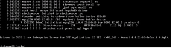
Create Swap Partition in a File
1. ssh to the os master on the PXE boot IP from PXE Boot Server.
2. Login as root and password.
3. Create file for swap partition:
osmaster:~ # dd if=/dev/zero of=/swap-0001 bs=1M count=2048
2048+0 records in
2048+0 records out
2147483648 bytes (2.1 GB) copied, 3.64515 s, 589 MB/s
4. Set up a swap area in a file:
osmaster:~ # mkswap /swap-0001
Setting up swapspace version 1, size = 2097148 KiB
no label, UUID=0f0f9606-dbe9-4301-9f65-293c3bab1346
5. To use swap file execute the below command:
osmaster:~ # swapon /swap-0001
6. Verify if the swap partition is being used:
osmaster:~ # swapon -s
Filename Type Size Used Priority
/swap-0001 file 2097148 0 -1
7. Add the following line (swap) to /etc/fstab for swap partition to be persistent after reboot:
vi /etc/fstab
/swap-0001 swap swap defaults 0 0
Update OS Master
To update the SUSE OS to the latest patch level, complete the following steps:
![]() This document assumes that the SUSE License key are available and registered username and password is available.
This document assumes that the SUSE License key are available and registered username and password is available.
1. ssh to the os master on the PXE boot IP from PXE Boot Server.
2. Login as root and password.
3. Assign IP address to the interface which can access the Internet or Proxy Server.
In this example HANA-Admin vNIC to access internet is used.
4. To configure the network interface on the OS, it is required to identify the mapping of the ethernet device on the OS to vNIC interface on the Cisco UCS.
5. From the OS execute the following command to get list of Ethernet device with MAC Address:
osmaster:~ # ifconfig -a|grep HWaddr
eth0 Link encap:Ethernet HWaddr 00:25:B5:1A:10:00
eth1 Link encap:Ethernet HWaddr 00:25:B5:00:0A:02
eth2 Link encap:Ethernet HWaddr 00:25:B5:00:0B:02
eth3 Link encap:Ethernet HWaddr 00:25:B5:00:0A:00
eth4 Link encap:Ethernet HWaddr 00:25:B5:00:0B:00
eth5 Link encap:Ethernet HWaddr 00:25:B5:00:0B:01
eth6 Link encap:Ethernet HWaddr 00:25:B5:00:0B:03
eth7 Link encap:Ethernet HWaddr 00:25:B5:00:0A:01
eth8 Link encap:Ethernet HWaddr 00:25:B5:00:0A:03
6. In Cisco UCS Manager, click the Servers tab in the navigation pane.
7. Select Service Profiles > root > HANA-Server01 Expand by clicking +.
8. Click vNICs.
9. On the Right pane list of the vNICs with MAC Address are listed.

![]() Take note of the MAC Address for the HANA-Admin vNIC is “00:25:B5:00:0A:03”
Take note of the MAC Address for the HANA-Admin vNIC is “00:25:B5:00:0A:03”
![]() By comparing MAC Address on the OS and UCS, eth8 on OS will carry the VLAN for HANA-Admin.
By comparing MAC Address on the OS and UCS, eth8 on OS will carry the VLAN for HANA-Admin.
10. Go to network configuration directory and create a configuration for eth8:
/etc/sysconfig/network
vi ifcfg-eth8
##
# HANA-Admin Network
##
BOOTPROTO='static'
IPADDR='<<IP Address for HANA-Admin>>/24'
MTU=''
NAME='VIC Ethernet NIC'
STARTMODE='auto'
11. Add default gateway:
cd /etc/sysconfig/network
vi routes
default <<IP Address of default gateway>> - -
12. Add the DNS IP if its required to access internet:
vi /etc/resolv.conf
nameserver <<IP Address of DNS Server1>>
nameserver <<IP Address of DNS Server2>>
13. Restart the network service for the change to take effect:
rcnetwork restart
14. Execute the following command to Register the SUSE:
suse_register -i -r -n -a email= <<email_address>> -a regcode-sles=<<registration_code>>
15. After the registration, the entire repository will be updated:
All services have been refreshed.
Repository 'SLES-for-SAP-Applications 11.3.3-1.17' is up to date.
All repositories have been refreshed.
Refreshing service 'nu_novell_com'.
Adding repository 'SLES12-SP2Updates' [done]
Adding repository 'SLES11-Extras' [done]
Adding repository 'SLES11-SP1-Pool' [done]
Adding repository 'SLES12-SP1Updates' [done]
Adding repository 'SLE11-HAE-SP3-Pool' [done]
Adding repository 'SLE11-HAE-SP3-Updates' [done]
Adding repository 'SLE12-SP2SAP-Updates' [done]
Adding repository 'SLES12-SP2Pool' [done]
Adding repository 'SLES12-SP1Extension-Store' [done]
Adding repository 'SLE12-SP2SAP-Pool' [done]
Adding repository 'SLE12-SP2Debuginfo-Pool' [done]
Adding repository 'SLE12-SP2WebYaST-1.3-Pool' [done]
Adding repository 'SLE11-SP1-Debuginfo-Updates' [done]
Adding repository 'SLES12-SP1Core' [done]
Adding repository 'SLES11-SP1-Updates' [done]
Adding repository 'SLES12-SP2Extension-Store' [done]
Adding repository 'SLE12-SP2WebYaST-1.3-Updates' [done]
Adding repository 'SLE11-SP1-Debuginfo-Pool' [done]
Adding repository 'SLE12-SP2Debuginfo-Updates' [done]
Adding repository 'SLE12-SP2Debuginfo-Core' [done]
Adding repository 'SLE12-SP2Debuginfo-Updates' [done]
All services have been refreshed.
Repository 'SLES-for-SAP-Applications 11.3.3-1.17' is up to date.
Retrieving repository 'SLE11-HAE-SP3-Pool' metadata [done]
Building repository 'SLE11-HAE-SP3-Pool' cache [done]
Retrieving repository 'SLE11-HAE-SP3-Updates' metadata [done]
Building repository 'SLE11-HAE-SP3-Updates' cache [done]
Retrieving repository 'SLE12-SP2WebYaST-1.3-Pool' metadata [done]
Building repository 'SLE12-SP2WebYaST-1.3-Pool' cache [done]
Retrieving repository 'SLE12-SP2WebYaST-1.3-Updates' metadata [done]
Building repository 'SLE12-SP2WebYaST-1.3-Updates' cache [done]
Retrieving repository 'SLE12-SP2SAP-Pool' metadata [done]
Building repository 'SLE12-SP2SAP-Pool' cache [done]
Retrieving repository 'SLE12-SP2SAP-Updates' metadata [done]
Building repository 'SLE12-SP2SAP-Updates' cache [done]
Retrieving repository 'SLES12-SP2Pool' metadata [done]
Building repository 'SLES12-SP2Pool' cache [done]
Retrieving repository 'SLES12-SP2Updates' metadata [done]
Building repository 'SLES12-SP2Updates' cache [done]
All repositories have been refreshed.
Registration finished successfully
16. Execute the following command to update the server:
zypper update
17. Follow the on-screen instruction to complete the update process.
18. Do not reboot the server until initrd and vmlinuz images are updated.
To update initrd image for PXE Boot environment, complete the following steps:
1. Log into PXE Boot server using ssh
2. Copy the initrd and vmlinux image from the system installed
![]() Make sure the suse_os_master volume is mounted on the /NFS/osmaster.
Make sure the suse_os_master volume is mounted on the /NFS/osmaster.
cp /NFS/osmaster/boot/initrd-3.0.101-0.40-default /tftpboot/suse/initrd-sles4sap
cp /NFS/osmaster/boot/vmlinuz-3.0.101-0.40-default /tftpboot/suse/vmlinuz-sles4sap
3. Update the PXE Configuration file:
vi /tftpboot/pxelinux.cfg/C0A87FC9
# UCS PXE Boot Definition
DISPLAY ../boot.msg
DEFAULT SLES4SAP
PROMPT 1
TIMEOUT 50
#
LABEL SLES4SAP
KERNEL suse/vmlinuz-sles4sap
APPEND initrd=suse/initrd-sles4sap rw rootdev=192.168.127.11:/suse_os_master ip=dhcp
4. ssh to the os master server with PXE boot IP (192.168.127.201) from PXE Boot Server.
5. Enter 'reboot'.
Install Cisco enic Driver
This section describes how to download the Cisco UCS Drivers ISO bundle, which contains most Cisco UCS Virtual Interface Card drivers.
1. In a web browser, navigate to http://www.cisco.com.
2. Under Support, click All Downloads.
3. In the product selector, click Products, then click Server - Unified Computing
4. If prompted, enter your Cisco.com username and password to log in.
![]() You must be signed in to download Cisco Unified Computing System (UCS) drivers.
You must be signed in to download Cisco Unified Computing System (UCS) drivers.
![]() Cisco UCS drivers are available for both Cisco UCS B-Series Blade Server Software and Cisco UCS C-Series Rack-Mount UCS-Managed Server Software.
Cisco UCS drivers are available for both Cisco UCS B-Series Blade Server Software and Cisco UCS C-Series Rack-Mount UCS-Managed Server Software.
5. Click Cisco UCS B-Series Blade Server Software.
6. Click on Cisco Unified Computing System (UCS) Drivers.
![]() The latest release version is selected by default. This document is built on Version 2.2(3)
The latest release version is selected by default. This document is built on Version 2.2(3)
7. Click on 3.1(2f) Version.
8. Download ISO image of Cisco UCS-related drivers.
9. Choose your download method and follow the prompts to complete your driver download.
10. After the download completes, browse the ISO to Cisco ucs-bxxx-drivers.2.2.3\Linux\Network\Cisco\M81KR\SLES\SLES11.3 and copy cisco-enic-kmp-default-2.1.1.75_3.0.76_0.11-0.x86_64.rpm to PXE Boot Server /NFS/software/SLES
11. ssh to PXE Boot Server as root.
12. Copy the rpm package to OS Master{
scp /NFS/software/SLES/cisco-enic-kmp-default-<latest version>.x86_64.rpm 192.168.127.201:/tmp/
cisco-enic-kmp-default--<latest version>. 100% 543KB 542.8KB/s 00:00
13. ssh to the os master on the PXE boot IP from PXE Boot Server as root.
14. Update the enic driver:
rpm -Uvh /tmp/cisco-enic-kmp-default--<latest version>.q.x86_64.rpm
Preparing... ########################################### [100%]
1:cisco-enic-kmp-default ########################################### [100%]
Kernel image: /boot/vmlinuz-3.0.101-0.40-default
Initrd image: /boot/initrd-3.0.101-0.40-default
KMS drivers: mgag200
Kernel Modules: hwmon thermal_sys thermal processor fan scsi_mod scsi_dh scsi_dh_alua scsi_dh_emc scsi_dh_hp_sw scsi_dh_rdac sunrpc nfs_acl auth_rpcgss fscache lockd nfs syscopyarea i2c-core sysfillrect sysimgblt i2c-algo-bit drm drm_kms_helper ttm mgag200 usb-common usbcore ohci-hcd uhci-hcd ehci-hcd xhci-hcd hid usbhid af_packet enic crc-t10dif sd_mod
Features: acpi kms usb network nfs resume.userspace resume.kernel
45343 blocks
To update the initrd image for PXE Boot environment, complete the following steps:
1. Log into PXE Boot server using ssh.
2. Copy the initrd and vmlinux image from the system installed.
![]() Make sure suse_os_master volume is mounted on the /NFS/osmaster..
Make sure suse_os_master volume is mounted on the /NFS/osmaster..
cd /NFS/osmaster
cp boot/initrd-4.4.21-69-default /tftpboot
cp boot/vmlinuz-4.4.21-69-default /tftpboot
3. ssh to the os master server with PXE boot IP (192.168.127.201) from PXE Boot Server.
4. Enter 'reboot'.
Operating System Configuration for SAP HANA
SAP HANA running on a SLES 11 SP3 system requires configuration changes on the OS level, to achieve best performance and a stable system.
Disabled Transparent Hugepages
With SLES11 SP3 the usage of Transparent Hugepages (THP) is generally activated for the Linux kernel. The THP allows the handling of multiple pages as Hugepages reducing the “translation look aside buffer” footprint (TLB), in situations where it might be useful. Due to the special manner of SAP HANA's memory management, the usage of THP may lead to hanging situations and performance degradations.
1. To disable the usage of Transparent Hugepages set the kernel settings at runtime:
echo never > /sys/kernel/mm/transparent_hugepage/enabled
![]() There is no need to shut down the database to apply this configuration. This setting is then valid until the next system start. To make this option persistent, integrate this command line within your system boot scripts (such as /etc/init.d/after.local).
There is no need to shut down the database to apply this configuration. This setting is then valid until the next system start. To make this option persistent, integrate this command line within your system boot scripts (such as /etc/init.d/after.local).
Configured C-States for Lower Latency in Linux
The Linux Kernel 3.0 includes a new cpuidle driver for recent Intel CPUs: intel_idle. This driver leads to a different behavior in C-states switching. The normal operating state is C0, when the processor is put to a higher C state, it will save power. But for low latency applications, the additional time needed to start the execution of the code again will cause performance degradations.
Therefore it is necessary to edit the boot loader configuration. The location of the boot loader configuration file is usually /etc/sysconfig/bootloader.
1. Edit this file and append the following value to the "DEFAULT_APPEND" parameter value:
intel_idle.max_cstate=1
With this a persistent change has been done for potential kernel upgrades and bootloader upgrades. For immediate configuration change, it is also necessary to append this parameter in the kernel command line of your current active bootloader file which is located on the PXE server under /tftpboot/pxelinux.cfg
2. Append the intel_idle value mentioned above only to the operational kernel's parameter line. The C states are disabled in BIOS but to be sure the C states are not used set the following parameter in addition to the previous one:
processor.max_cstate=1
3. The CPU speed must be set to performance for SAP HANA so that all Cores run all time with highest frequency:
/usr/bin/cpupower frequency-set –g performance 2>&1
4. To make this option persistent, integrate this command line within your system boot scripts (e.g. /etc/init.d/after.local).
Configured Swappiness
1. Set swappiness to 10 to avoid swapping:
Echo 10 > /proc/sys/vm/swappiness
RSS/RPS Settings on the OS
To get use of the RSS setting in the Adapter policy, it is necesary to configure the Receive Side Packet Steering (RPS) on the OS level.
RPS distributes the load of received packet processing across multiple CPUs. Problem statement: Protocol processing done in the NAPI context for received packets is serialized per device queue and becomes a bottleneck under high packet load. This substantially limits pps that can be achieved on a single queue NIC and provides no scaling with multiple cores.
To configure the OS optimization settings on the OS Master, complete the following steps:
1. ssh to the os master on the PXE boot IP from PXE Boot Server.
2. Login as root and password.
3. Create a file /etc/init.d/after.local:
vi /etc/init.d/after.local
#!/bin/bash
# (c) Cisco Systems Inc. 2017
/usr/bin/cpupower frequency-set -g performance 2>&1
echo never > /sys/kernel/mm/transparent_hugepage/enabled # from kernel >= 3.0.80.7 THP can be enabled again
. /etc/rc.status
# set sappiness to 10 to aviod swapping
echo "Set swappiness to 10 to avoid swapping"
echo 10 > /proc/sys/vm/swappiness
. /etc/rc.status
4. Add the following lines to /etc/sysctl.conf:
#disable IPv6
net.ipv6.conf.all.disable_ipv6 = 1
#
# Controls IP packet forwarding
net.ipv4.ip_forward = 0
# Do not accept source routing
net.ipv4.conf.default.accept_source_route = 0
# Controls the use of TCP syncookies
net.ipv4.tcp_syncookies = 1
fs.inotify.max_user_watches = 65536
kernel.shmmax = 9223372036854775807
kernel.sem = 1250 256000 100 8192
kernel.shmall = 1152921504606846720
kernel.shmmni = 524288
# SAP HANA Database
# Next line modified for SAP HANA Database on 2016.01.04_06.52.38
vm.max_map_count=588100000
fs.file-max = 20000000
fs.aio-max-nr = 196608
vm.memory_failure_early_kill = 1
#
net.core.rmem_max = 16777216
net.core.wmem_max = 16777216
net.core.rmem_default = 16777216
net.core.wmem_default = 16777216
##
net.core.optmem_max = 16777216
net.core.netdev_max_backlog = 300000
net.ipv4.tcp_slow_start_after_idle = 0
net.ipv4.conf.default.promote_secondaries = 1
net.ipv4.conf.all.promote_secondaries = 1
net.ipv4.icmp_echo_ignore_broadcasts = 1
net.ipv4.tcp_rmem = 65536 16777216 16777216
net.ipv4.tcp_wmem = 65536 16777216 16777216
##
net.core.somaxconn=1024
net.ipv4.conf.default.accept_source_route = 0
net.ipv4.tcp_syncookies = 1
##
net.ipv4.tcp_no_metrics_save = 1
net.ipv4.tcp_moderate_rcvbuf = 1
net.ipv4.tcp_window_scaling = 1
net.ipv4.tcp_timestamps = 0
net.ipv4.tcp_sack = 0
net.ipv4.tcp_dsack = 0
net.ipv4.tcp_fsack = 0
net.ipv4.tcp_max_syn_backlog = 16348
net.ipv4.tcp_synack_retries = 3
net.ipv4.tcp_retries2 = 6
net.ipv4.tcp_keepalive_time = 1000
net.ipv4.tcp_tw_recycle = 1
net.ipv4.tcp_tw_reuse = 1
# Linux SAP swappiness recommendation
vm.swappiness=10
# Next line added for SAP HANA Database on 2015.09.16_02.09.34
net.ipv4.ip_local_port_range=40000 65300
#For background information, see SAP Note 2205917 and 1557506
vm.pagecache_limit_mb = 0
vm.pagecache_limit_ignore_dirty = 1
#
sunrpc.tcp_slot_table_entries = 128
sunrpc.tcp_max_slot_table_entries = 128
5. Update the PXE Configuration file on the PXE Boot server:
vi /tftpboot/pxelinux.cfg/C0A87FC9
# UCS PXE Boot Definition
DISPLAY ../boot.msg
DEFAULT SLES4SAP
PROMPT 1
TIMEOUT 50
#
LABEL SLES4SAP
KERNEL suse/vmlinuz-sles4sap
APPEND initrd=suse/initrd-sles4sap rw rootdev=192.168.127.11:/suse_os_master intel_idle.max_cstate=1 processor.max_cstate=1 ip=dhcp
6. Disable (blacklist) the unnecessary driver:
vi /etc/modprobe.d/50-blacklist.conf
#
# disable modules for NFS and HANA
blacklist kvm
blacklist kvm_intel
blacklist iTCO_wdt
blacklist iTCO_vendor_support
7. Set the sunrpc limits to 128:
vi /etc/modprobe.d/sunrpc-local.conf
options sunrpc tcp_max_slot_table_entries=128
8. Prepare the Dracut configuration file:
vi /NFS/SLES12SP1_osmaster/etc/dracut.conf
# PUT YOUR CONFIG HERE OR IN separate files named *.conf
# in /etc/dracut.conf.d
# SEE man dracut.conf(5)
# Sample dracut config file
#logfile=/var/log/dracut.log
#fileloglvl=6
# Exact list of dracut modules to use. Modules not listed here are not going
# to be included. If you only want to add some optional modules use
# add_dracutmodules option instead.
#dracutmodules+=""
# dracut modules to omit
#omit_dracutmodules+=""
# dracut modules to add to the default
add_dracutmodules+="systemd ssh-client nfs network base"
# additional kernel modules to the default
add_drivers+="sunrpc nfs nfs_acl nfsv3 fnic enic igb ixgbe lpfc"
# list of kernel filesystem modules to be included in the generic initramfs
#filesystems+=""
# build initrd only to boot current hardware
hostonly="no"
#
...
9. Create a server independent initrd:
dracut –v –f /boot/initrd_nfsboot_SLES12SP2_<number>.img
ls -ltr /boot/initrd_nfsboot_SLES12SP2_001.img
-rw------- 1 root root 46723100 Jun 9 2017 /boot/initrd_nfsboot_SLES12SP2_001.img
![]() This initrd can now be transferred to the PXE server to boot from the next time.
This initrd can now be transferred to the PXE server to boot from the next time.
Cloning OS Volumes
After OS Master image is created, prepare the os image for cloning.
Clean UP Master OS Image
1. ssh to osmaster.
2. Remove the SUSE Registration information.
![]() This step is required to create a master image without the registration information. After OS deployment, register each server with SUSE for OS support.
This step is required to create a master image without the registration information. After OS deployment, register each server with SUSE for OS support.
3. List the zypper service with zypper ls:
zypper ls
# | Alias | Name | Enabled | Refresh | Type
--+---------------------------------------+--------------------------+----+-------+------
1 | nu_novell_com | nu_novell_com | Yes | No | ris
2 | SLES-for-SAP-Applications 12.2. | SLES-for-SAP-Applications 12.2 | Yes | Yes | yast2
4. Remove the Update Service zypper removeservice nu_novell_com:
zypper removeservice nu_novell_com
Removing service 'nu_novell_com':
Removing repository 'SLE12-HAE-SP2-Pool' [done]
Removing repository 'SLE11-HAE-SP3-Updates' [done]
Removing repository 'SLE11-SP1-Debuginfo-Pool' [done]
Removing repository 'SLE11-SP1-Debuginfo-Updates' [done]
Removing repository 'SLE12-SP2Debuginfo-Core' [done]
Removing repository 'SLE12-SP2Debuginfo-Updates' [done]
Removing repository 'SLE12-SP2WebYaST-1.3-Pool' [done]
Removing repository 'SLE12-SP2WebYaST-1.3-Updates' [done]
Removing repository 'SLE12-SP2Debuginfo-Pool' [done]
Removing repository 'SLE12-SP2Debuginfo-Updates' [done]
Removing repository 'SLE12-SP2SAP-Pool' [done]
Removing repository 'SLE12-SP2SAP-Updates' [done]
Removing repository 'SLES12-SP1Core' [done]
Removing repository 'SLES12-SP1Extension-Store' [done]
Removing repository 'SLES12-SP1Updates' [done]
Removing repository 'SLES12-SP2Extension-Store' [done]
Removing repository 'SLES12-SP2Pool' [done]
Removing repository 'SLES12-SP2Updates' [done]
Service 'nu_novell_com' has been removed.
5. Remove registration credentials:
cishana01:~ # rm /etc/zypp/credentials.d/NCCcredentials
cishana01:~ # rm /var/cache/SuseRegister/lastzmdconfig.cache
6. Shutdown the OS Master Server by issuing “halt” command.
7. Log into PXE Boot server using ssh.
![]() Make sure the suse_os_master volume is mounted on the /NFS/osmaster.
Make sure the suse_os_master volume is mounted on the /NFS/osmaster.
8. Clear the fstab entry:
vi /NFS/osmaster/etc/fstab
delete the entry
192.168.127.11:/suse_os_master / nfs defaults 0 0
9. Clear the System logs:
rm /NFS/osmaster/var/log/* -r
10. Clear the Ethernet Persistent network information:
cat /dev/null > /NFS/osmaster/etc/udev/rules.d/70-persistent-net.rules
11. Remove any Ethernet configuration file except eth0:
rm /NFS/osmaster/etc/sysconfig/network/ifcfg-eth<<1-7>>
12. Remove default gateway:
rm /NFS/osmaster/etc/sysconfig/network/routes
13. Shut the OS master by executing “halt”.
Storage Clone of OS Volume
To clone the OS master image (FlexClone License required) to new the host, complete the following steps:
1. Log in to Storage shell.
2. Create a Clone of OS master volume:
volume clone create -flexclone server01 -parent-volume suse_os_master -vserver infra_vs1 -junction-path /server01 -space-guarantee none
3. Split the volume from OS master volume:
AFF A300-cluster::> volume clone split start -flexclone server01
Warning: Are you sure you want to split clone volume server01 in Vserver
infra_vs1 ? {y|n}: y
[Job 1372] Job is queued: Split server01.
4. Check for status of Clone split:
AFF A300-cluster::> volume clone split status -flexclone server01
Inodes Blocks
--------------------- ---------------------
Vserver FlexClone Processed Total Scanned Updated % Complete
--------- ------------- ---------- ---------- ---------- ---------- ----------
infra_vs1 server01 149558 253365 541092 538390 59
5. When the clone split is completed:
AFF A300-cluster::> volume clone split status -flexclone server01
There are no entries matching your query.
6. Repeat the steps 2-3 for each server to deploy OS image.
Manual Clone of OS Volume
If the FlexClone license is not available it is also possible to distribute the OS Image.
1. Create the OS Volume on the storage and use qtrees to separate each OS:
vol create -vserver Infra-SVM -volume PXE_OS -aggregate hana01 -size 200GB -state online -policy default -unix-permissions ---rwxr-xr-x -type RW -snapshot-policy default
qtree create -vserver Infra-SVM -volume PXE_OS -qtree Server01
qtree create -vserver Infra-SVM -volume PXE_OS -qtree Server02
qtree create -vserver Infra-SVM -volume PXE_OS -qtree Server03
qtree create -vserver Infra-SVM -volume PXE_OS -qtree Server04
qtree create -vserver Infra-SVM -volume PXE_OS -qtree Server05
qtree create -vserver Infra-SVM -volume PXE_OS -qtree Server06
qtree create -vserver Infra-SVM -volume PXE_OS -qtree Server07
qtree create -vserver Infra-SVM -volume PXE_OS -qtree Server08
qtree create -vserver Infra-SVM -volume PXE_OS -qtree Server09
qtree create -vserver Infra-SVM -volume PXE_OS -qtree Server10
qtree create -vserver Infra-SVM -volume PXE_OS -qtree Server11
qtree create -vserver Infra-SVM -volume PXE_OS -qtree Server12
volume mount -vserver Infra-SVM -volume PXE_OS -junction-path /PXE_OS
2. On the management server create the mount points for the OS copies.
mkdir –p /NFS/PXE_OS
3. Add those two lines in the fstab of the mgmtsrv01.
vi /etc/fstab
lif-pxe-1:/tftpboot /tftpboot nfs defaults 0 0
lif-pxe-1:/PXE_OS /NFS/PXE_OS nfs defaults 0 0
4. mount the two filesystems to the management server mgmtsrv01.
mount –a
df -hT
Filesystem Type Size Used Avail Use% Mounted on
/dev/sda2 ext3 58G 27G 30G 48% /
udev tmpfs 3.9G 112K 3.9G 1% /dev
tmpfs tmpfs 8.0G 724K 8.0G 1% /dev/shm
lif-pxe-1:/tftpboot nfs 973M 1.1M 972M 1% /tftpboot
lif-pxe-1:/PXE_OS nfs 190G 320K 190G 1% /NFS/PXE_OS
cd /NFS/PXE_OS/
ls –l
drwxr-xr-x 2 root root 4096 Mar 31 2017 Server01
drwxr-xr-x 2 root root 4096 Mar 31 2017 Server02
drwxr-xr-x 2 root root 4096 Mar 31 2017 Server03
drwxr-xr-x 2 root root 4096 Mar 31 2017 Server04
drwxr-xr-x 2 root root 4096 Mar 31 2017 Server05
drwxr-xr-x 2 root root 4096 Mar 31 2017 Server06
drwxr-xr-x 2 root root 4096 Mar 31 2017 Server07
drwxr-xr-x 2 root root 4096 Mar 31 2017 Server08
drwxr-xr-x 2 root root 4096 Mar 31 2017 Server09
drwxr-xr-x 2 root root 4096 Mar 31 2017 Server10
drwxr-xr-x 2 root root 4096 Mar 31 2017 Server11
drwxr-xr-x 2 root root 4096 Mar 31 2017 Server12
PXE Configuration for Additional Server
The PXE boot environment will search for a configuration file based on its boot IP assigned through DHCP.
1. To calculate the filename run “gethostip”, the output is a hex representation of the IP address will be configuration filename:
gethostip 192.168.127.201
192.168.127.201 192.168.127.201 C0A87FC9
2. The file name “C0A87FC9” contains the PXE boot configuration for server with IP 192.168.127.201.
3. ssh to PXE boot serve.r
4. Go to PXE boot configuration directory:
cd /tftpboot/pxelinux.cfg/
5. Create a configuration file for each server:
vi C0A87FC9
# UCS PXE Boot Definition
DISPLAY ../boot.msg
DEFAULT SLES4SAP
PROMPT 1
TIMEOUT 50
#
LABEL SLES4SAP
KERNEL suse/vmlinuz-sles4sap
APPEND initrd=suse/initrd-sles4sap rw rootdev=192.168.127.11:/server01 intel_idle.max_cstate=0 processor.max_cstate=0 ip=dhcp
6. Repeat the previous step for each server.
7. Example: PXE Boot configuration file for server with dhcp ip 192.168.201.202:
gethostip 192.168.127.202
192.168.127.202 192.168.127.202 C0A87FCA
vi C0A87FCA
# UCS PXE Boot Definition
DISPLAY ../boot.msg
DEFAULT SLES4SAP
PROMPT 1
TIMEOUT 50
#
LABEL SLES4SAP
KERNEL suse/vmlinuz-sles4sap
APPEND initrd=suse/initrd-sles4sap rw rootdev=192.168.127.11:/server02 intel_idle.max_cstate=1 processor.max_cstate=1 ip=dhcp
Boot the Server
1. In Cisco UCS Manager, click the Servers tab in the navigation pane.
2. Select Service Profile Templates > root > Service Profiles.
3. Expand the tree and Right-click Service Template HANA-Server02 and select Boot Server
Post Installation OS Customization
After the OS is deployed from the Master image, customization is required for each server.
Hostnames
The operating system must be configured such a way that the short name of the server is displayed for the command ‘hostname’ and Full Qualified Host Name is displayed with the command ‘hostname –d’
1. ssh to the Server to PXE boot IP from PXE Boot Server.
2. Login as root and password.
3. Edit the Hostname:
vi /etc/HOSTNAME
<<hostname>>.<<Domain Name>>
IP Address
1. Assign the IP address to each interface.
2. ssh to the Server on the PXE boot IP from PXE Boot Server.
3. Login as root and password.
4. To configure the network interface on the OS, it is necessary to identify the mapping of the ethernet device on the OS to vNIC interface on the Cisco UCS. From the OS execute the below command to get list of Ethernet device with MAC Address.
ifconfig -a |grep HWaddr
eth0 Link encap:Ethernet HWaddr 00:25:B5:1A:10:00
eth1 Link encap:Ethernet HWaddr 00:25:B5:00:0A:02
eth2 Link encap:Ethernet HWaddr 00:25:B5:00:0B:02
eth3 Link encap:Ethernet HWaddr 00:25:B5:00:0A:00
eth4 Link encap:Ethernet HWaddr 00:25:B5:00:0B:00
eth5 Link encap:Ethernet HWaddr 00:25:B5:00:0B:01
eth6 Link encap:Ethernet HWaddr 00:25:B5:00:0B:03
eth7 Link encap:Ethernet HWaddr 00:25:B5:00:0A:01
eth8 Link encap:Ethernet HWaddr 00:25:B5:00:0A:03
5. In Cisco UCS Manager, click the Servers tab in the navigation pane.
6. Select Service Profiles > root > HANA-Server01 Expand by clicking +.
7. Click vNICs.
8. On the right pane list of the vNICs with MAC Address are listed.
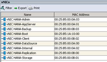
9. Note the MAC Address of the HANA-Admin vNIC “00:25:B5:00:0A:03”.
10. By comparing MAC Address on the OS and Cisco UCS, eth8 on OS will carry the VLAN for HANA-Admin.
11. Go to network configuration directory and create a configuration for eth8.
/etc/sysconfig/network
vi ifcfg-eth8
##
# HANA-Admin Network
##
BOOTPROTO='static'
IPADDR='<<IP Address for HANA-Admin>>/24'
MTU='<<9000 or 1500>>'
NAME='VIC Ethernet NIC'
STARTMODE='auto'
12. Repeat the steps 8 to 10 for each vNIC interface.
13. Add default gateway.
cd /etc/sysconfig/network
vi routes
default <<IP Address of default gateway>> - -
Network Time
It is important that the time on all components used for SAP HANA must be in sync. The configuration of NTP is important and should be configured on all systems, as provided below:
vi /etc/ntp.conf
server <NTP-SERVER IP>
fudge <NTP-SERVER IP> stratum 10
keys /etc/ntp.keys
trustedkey 1
DNS
Domain Name Service configuration must be done based on the local requirements.
1. Configuration Example:
vi /etc/resolv.conf
nameserver <<IP Address of DNS Server1>>
nameserver <<IP Address of DNS Server2>>
HOSTS
For SAP HANA Scale-Out system, all nodes should be able to resolve the Internal network IP address. Below is an example of an 8 node host file with all the network defined in the /etc/hosts file:
cishana01:~ # cat /etc/hosts
#
# hosts This file describes a number of hostname-to-address
# mappings for the TCP/IP subsystem. It is mostly
# used at boot time, when no name servers are running.
# On small systems, this file can be used instead of a
# "named" name server.
# Syntax:
#
# IP-Address Full-Qualified-Hostname Short-Hostname
#
127.0.0.1 localhost
# special IPv6 addresses
::1 localhost ipv6-localhost ipv6-loopback
fe00::0 ipv6-localnet
ff00::0 ipv6-mcastprefix
ff02::1 ipv6-allnodes
ff02::2 ipv6-allrouters
ff02::3 ipv6-allhosts
#
## NFS Storage
172.29.110.12 lifdata01
172.29.110.13 lifdata02
192.168.127.13 nfssap
#
## Internal Network
#
172.29.220.201 cishana01.ciscolab.local cishana01
172.29.220.202 cishana02.ciscolab.local cishana02
172.29.220.203 cishana03.ciscolab.local cishana03
172.29.220.204 cishana04.ciscolab.local cishana04
172.29.220.205 cishana05.ciscolab.local cishana05
172.29.220.206 cishana06.ciscolab.local cishana06
172.29.220.207 cishana07.ciscolab.local cishana07
172.29.220.208 cishana08.ciscolab.local cishana08
#
## Storage Network
#
172.29.110.201 cishana01s.ciscolab.local cishana01s
172.29.110.202 cishana02s.ciscolab.local cishana02s
172.29.110.203 cishana03s.ciscolab.local cishana03s
172.29.110.204 cishana04s.ciscolab.local cishana04s
172.29.110.205 cishana05s.ciscolab.local cishana05s
172.29.110.206 cishana06s.ciscolab.local cishana06s
172.29.110.207 cishana07s.ciscolab.local cishana07s
172.29.110.208 cishana08s.ciscolab.local cishana08s
#
## Client Network
#
172.29.222.201 cishana01c.ciscolab.local cishana01c
172.29.222.202 cishana02c.ciscolab.local cishana02c
172.29.222.203 cishana03c.ciscolab.local cishana03c
172.29.222.204 cishana04c.ciscolab.local cishana04c
172.29.222.205 cishana05c.ciscolab.local cishana05c
172.29.222.206 cishana06c.ciscolab.local cishana06c
172.29.222.207 cishana07c.ciscolab.local cishana07c
172.29.222.208 cishana08c.ciscolab.local cishana08c
#
## AppServer Network
#
172.29.223.201 cishana01a.ciscolab.local cishana01a
172.29.223.202 cishana02a.ciscolab.local cishana02a
172.29.223.203 cishana03a.ciscolab.local cishana03a
172.29.223.204 cishana04a.ciscolab.local cishana04a
172.29.223.205 cishana05a.ciscolab.local cishana05a
172.29.223.206 cishana06a.ciscolab.local cishana06a
172.29.223.207 cishana07a.ciscolab.local cishana07a
172.29.223.208 cishana08a.ciscolab.local cishana08a
#
## Admin Network
#
172.29.112.201 cishana01m.ciscolab.local cishana01m
172.29.112.202 cishana02m.ciscolab.local cishana02m
172.29.112.203 cishana03m.ciscolab.local cishana03m
172.29.112.204 cishana04m.ciscolab.local cishana04m
172.29.112.205 cishana05m.ciscolab.local cishana05m
172.29.112.206 cishana06m.ciscolab.local cishana06m
172.29.112.207 cishana07m.ciscolab.local cishana07m
172.29.112.208 cishana08m.ciscolab.local cishana08m
#
## Backup Network
#
172.29.221.201 cishana01b.ciscolab.local cishana01b
172.29.221.202 cishana02b.ciscolab.local cishana02b
172.29.221.203 cishana03b.ciscolab.local cishana03b
172.29.221.204 cishana04b.ciscolab.local cishana04b
172.29.221.205 cishana05b.ciscolab.local cishana05b
172.29.221.206 cishana06b.ciscolab.local cishana06b
172.29.221.207 cishana07b.ciscolab.local cishana07b
172.29.221.208 cishana08b.ciscolab.local cishana08b
#
## DataSource Network
#
172.29.224.201 cishana01d.ciscolab.local cishana01d
172.29.224.202 cishana02d.ciscolab.local cishana02d
172.29.224.203 cishana03d.ciscolab.local cishana03d
172.29.224.204 cishana04d.ciscolab.local cishana04d
172.29.224.205 cishana05d.ciscolab.local cishana05d
172.29.224.206 cishana06d.ciscolab.local cishana06d
172.29.224.207 cishana07d.ciscolab.local cishana07d
172.29.224.208 cishana08d.ciscolab.local cishana08d
#
## Replication Network
#
172.29.225.201 cishana01r.ciscolab.local cishana01r
172.29.225.202 cishana02r.ciscolab.local cishana02r
172.29.225.203 cishana03r.ciscolab.local cishana03r
172.29.225.204 cishana04r.ciscolab.local cishana04r
172.29.225.205 cishana05r.ciscolab.local cishana05r
172.29.225.206 cishana06r.ciscolab.local cishana06r
172.29.225.207 cishana07r.ciscolab.local cishana07r
172.29.225.208 cishana08r.ciscolab.local cishana08r
#
## IPMI Address
#
172.25.186.141 cishana01-ipmi
172.25.186.142 cishana02-ipmi
172.25.186.143 cishana03-ipmi
172.25.186.144 cishana04-ipmi
172.25.186.145 cishana05-ipmi
172.25.186.146 cishana06-ipmi
172.25.186.147 cishana07-ipmi
172.25.186.148 cishana08-ipmi
SSH Keys
The SSH Keys must be exchanged between all nodes in a SAP HANA Scale-Out system for user ‘root’ and user <SID>adm.
1. Generate the rsa public key by executing the command ssh-keygen -b 2048
cishana01:~ # ssh-keygen -b 2048
Generating public/private rsa key pair.
Enter file in which to save the key (/root/.ssh/id_rsa):
Created directory '/root/.ssh'.
Enter passphrase (empty for no passphrase):
Enter same passphrase again:
Your identification has been saved in /root/.ssh/id_rsa.
Your public key has been saved in /root/.ssh/id_rsa.pub.
The key fingerprint is:
5c:5b:e9:cd:f9:73:71:39:ec:ed:80:a7:0a:6c:3a:48 [MD5] root@cishana01.ciscolab.local
The key's randomart image is:
+--[ RSA 2048]----+
| |
| . |
| . o |
| . . + o...|
| S . . +=.|
| .. ... .|
+--[MD5]----------+
2. The SSH Keys must be exchanged between all nodes in a SAP HANA Scale-Out system for user ‘root’ and user.
3. Exchange the rsa public key by executing the following command from the first server to the remaining servers in the scale-out system.
“ssh-copy-id -i /root/.ssh/id_rsa.pub cishana02”
cishana01:/ # ssh-copy-id -i /root/.ssh/id_rsa.pub cishana02
The authenticity of host 'cishana02 (172.29.220.202)' can't be established.
ECDSA key fingerprint is 93:b9:d5:1a:97:a9:32:10:4f:c2:ef:99:b8:7c:9d:52 [MD5].
Are you sure you want to continue connecting (yes/no)? yes
Password:
Number of key(s) added: 1
Now try logging into the machine, with: "ssh 'cishana02'"
and check to make sure that only the key(s) you wanted were added.
4. Repeat the steps 1-3 for all the servers in the single SID HANA system.
(Optional) Syslog
For a centralized monitoring of all SAP HANA nodes, it is recommended that syslog-ng is configured to forward all messages to a central syslog server
1. Change the syslog-ng.conf file as shown below:
vi /etc/syslog-ng/syslog-ng.conf
…
…
…
#
# Enable this and adopt IP to send log messages to a log server.
#
destination logserver1 { udp("<SYSLOG-SERVER IP>" port(<SYSLOG-Server PORT>)); };
log { source(src); destination(logserver1); };
destination logserver2 { udp("<SYSLOG-SERVER IP>" port(<SYSLOG-Server PORT>)); };
log { source(src); destination(logserver2); };
2. Restart the syslog daemon:
/etc/init.d/syslog restart
Operating System Installation Red Hat Enterprise Linux 7.2
This section describes the OS installation based on the PXE Boot Option. RHEL does not provide the option to install the OS directly on an NFS location. You must first install the OS on a local hard disk and then copy the OS via “rsync” over to the NFS share.
![]() Use the SAP HANA Installation Guide for OS customization.
Use the SAP HANA Installation Guide for OS customization.
1. In Cisco UCS Manager, click the Servers tab in the navigation pane.
2. Select Service Profiles > root > HANA-Server01.
3. Click KVM Console.
4. When the KVM Console is launched, click Boot Server.

5. If you using CD click Virtual Media > Activate Virtual Devices.
6. Select Accept this Session for Unencrypted Virtual Media Session then click Apply.
7. Click Virtual Media and Choose Map CD/DVD.
8. Click Browse to navigate ISO media location.
9. Click Map Device.
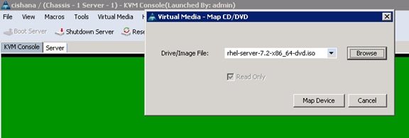
The Select Installation screenshot is shown below:
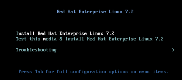
10. Do not change the system Language (must be English/English).
11. Choose Keyboard and configure your layout.
12. Configure the right Timezone and Time.
13. Click the ‘Security Policy’ to deactivate the security policy.
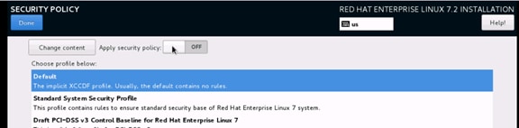
14. Leave the Software section selections as default (Minimal Installation).
15. Click Installation destination.
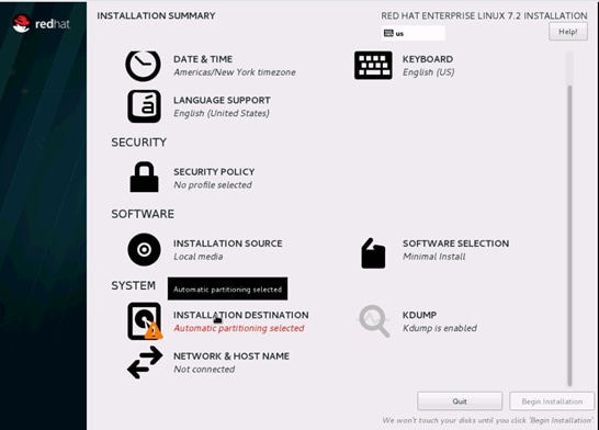
The next screen will list all the virtual drives that was created in the RAID configuration.
16. Double-click the drive.
17. From the ‘Other Storage options’ select ‘I will configure partitioning’.
18. Click Done.
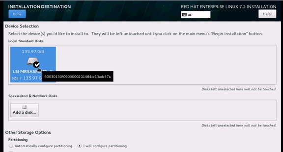
19. Select Standard Partition and then select “Click here to create them automatically.”
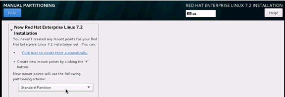
20. Confirm the default Partition table.
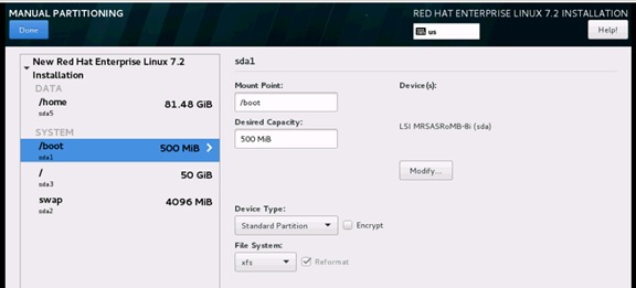
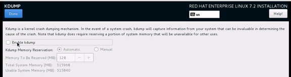
22. Start the Installation and then setup the root password.
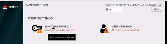
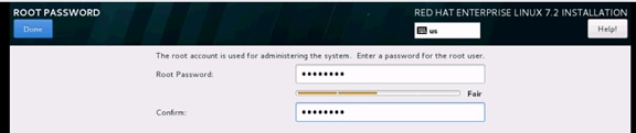
23. If all packages are installed reboot the system.

Post Installation Tasks
Configuring the Network
In RHEL 7, system and udev support a number of different naming schemes. By default, fixed names are assigned based on firmware, topology, and location information: for example, enp72s0.
With this naming convention, although names remain fixed even if hardware is added or removed, names often are more difficult to read than with traditional kernel-native ethX naming: that is, eth0, etc.
Another convention for naming network interfaces, biosdevnames, is available with installation.
If you require to go back the this traditional device names set these parameter later on in the PXE configuration net.ifnames=0 biosdevname=0
Also, you can disable IPv6 support ipv6.disable=1.
1. Log in to the newly installed system as root.
2. Configure the network.
3. Get the MAC addresses from Cisco UCS Manager.
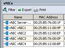
The order in this ecample: vNIC1 = Admin LAN ; vNIC2 = PXE Boot; vNIC3 = Access LAN ; vNIC4 = NFS LAN
1. Configure the Access network, default GW and the resolv.conf file to be able to reach the RHEL Satelite Server.
nmcli con add con-name Access ifname enp10s0 type ethernet ip4 10.1.1.10/24 gw4 10.1.1.1
cat /etc/sysconfig/network-scripts/ifcfg-Access
TYPE=Ethernet
BOOTPROTO=none
IPADDR=>>IP Address of the Access LAN>>
PREFIX=24
GATEWAY=10.1.1.1
DEFROUTE=yes
IPV4_FAILURE_FATAL=no
IPV6INIT=no
NAME=Access
UUID=d6bcdbc9-ded6-43a6-b854-f5d0ca2370b2
DEVICE=enp14s0
ONBOOT=yes
DNS1=10.17.1.20
DOMAIN=customer.com
2. Restart the Network.
systemctl restart network
Updating the RedHat System
In order to patch the system, the repository must be updated. Note that the installed system does not include any update information. In order to patch the Redhat System, it must be registered and attached to a valid.
It is recommended to check frequently the SAP recommendation in the SAP Note:
SAP Note 2292690 - SAP HANA DB Recommended OS Settings for RHEL 7.2
Subscription. The following line will register the installation and update the repository information.
subscription-manager register --username <<username>> --password <<password>> --force --auto-attach
yum -y install yum-versionlock
subscription-manager release --set=7.2
1. Apply the security updates. Typically, the kernel is updated as well:
yum --security update
2. Install the base package group:
yum -y groupinstall base
3. Install dependencies in accordance with the SAP HANA Server Installation and Update Guide and the numactl package if the benchmark HWCCT is to be used:
yum install cairo expect graphviz iptraf-ng krb5-workstation krb5-libs libcanberra-gtk2 libicu libpng12 libssh2 libtool-ltdl lm_sensors nfs-utils ntp ntpdate numactl openssl098e openssl PackageKit-gtk3-module rsyslog sudo tcsh xorg-x11-xauth xulrunner screen gtk2 gcc glib glibc-devel glib-devel kernel-devel libstdc++-devel redhat-rpm-config rpm-build zlib-devel
4. Install and enable the tuned profiles for HANA:
yum install tuned-profiles-sap-hana
systemctl start tuned
systemctl enable tuned
tuned-adm profile sap-hana
5. Disable the nomad:
systemctl stop numad
systemctl disable numad
6. Run now the full update of all packages:
yum -y update
7. Download and install the libstdc++5 library See: 2338763 - Linux: Running SAP applications compiled with GCC 5.x Download from RedHat: compat-sap-c++-5-5.3.1-10
rpm –Uvh compat-sap-c++-5-5.3.1-10.el7_3.x86_64.rpm
8. Reboot the machine and use the new kernel.
9. Disable SELinux:
vi /etc/sysconfig/selinux
# This file controls the state of SELinux on the system.
# SELINUX= can take one of these three values:
# enforcing - SELinux security policy is enforced.
# permissive - SELinux prints warnings instead of enforcing.
# disabled - No SELinux policy is loaded.
SELINUX=disabled
# SELINUXTYPE= can take one of these two values:
# targeted - Targeted processes are protected,
# mls - Multi Level Security protection.
SELINUXTYPE=targeted
10. Adjust the sunrcp slot table entries:
vi /etc/modprobe.d/sunrpc-local.conf
options sunrpc tcp_max_slot_table_entries=128
11. Tuned SAP HANA Profile:
tuned-adm profile sap-hana
systemctl enable tuneda
12. Disabling the firewall:
systemctl disable firewalld.service
13. Disabling the LVM2:
systemctl disable lvm2-lvmetad.socket
systemctl disable lvm2-lvmpolld.socket
systemctl disable lvm2-lvmetad.service
systemctl disable lvm2-monitor.service
systemctl disable dm-event.socket
14. Disabling the KVM and iTCO watchdog:
vi /etc/modprobe.d/local-blacklist.conf
blacklist kvm
blacklist iTCO_wdt
blacklist iTCO_vendor_support
15. Sysctl.conf: The following parameters must be set in /etc/sysctl.conf:
#disable IPv6
net.ipv6.conf.all.disable_ipv6 = 1
#
# Controls IP packet forwarding
net.ipv4.ip_forward = 0
# Do not accept source routing
net.ipv4.conf.default.accept_source_route = 0
# Controls the use of TCP syncookies
net.ipv4.tcp_syncookies = 1
fs.inotify.max_user_watches = 65536
kernel.shmmax = 9223372036854775807
kernel.sem = 1250 256000 100 8192
kernel.shmall = 1152921504606846720
kernel.shmmni = 524288
# SAP HANA Database
# Next line modified for SAP HANA Database on 2016.01.04_06.52.38
vm.max_map_count=588100000
fs.file-max = 20000000
fs.aio-max-nr = 196608
vm.memory_failure_early_kill = 1
net.core.rmem_max = 16777216
net.core.wmem_max = 16777216
net.core.rmem_default = 16777216
net.core.wmem_default = 16777216
##
net.core.optmem_max = 16777216
net.core.netdev_max_backlog = 300000
net.ipv4.tcp_slow_start_after_idle = 0
net.ipv4.conf.default.promote_secondaries = 1
net.ipv4.conf.all.promote_secondaries = 1
net.ipv4.icmp_echo_ignore_broadcasts = 1
net.ipv4.tcp_rmem = 65536 16777216 16777216
net.ipv4.tcp_wmem = 65536 16777216 16777216
##
net.core.somaxconn=1024
net.ipv4.conf.default.accept_source_route = 0
net.ipv4.tcp_syncookies = 1
net.ipv4.tcp_no_metrics_save = 1
net.ipv4.tcp_moderate_rcvbuf = 1
net.ipv4.tcp_window_scaling = 1
net.ipv4.tcp_timestamps = 0
net.ipv4.tcp_sack = 0
net.ipv4.tcp_dsack = 0
net.ipv4.tcp_fsack = 0
net.ipv4.tcp_max_syn_backlog = 16348
net.ipv4.tcp_synack_retries = 3
net.ipv4.tcp_retries2 = 6
net.ipv4.tcp_keepalive_time = 1000
net.ipv4.tcp_tw_recycle = 1
net.ipv4.tcp_tw_reuse = 1
# Linux SAP swappiness recommendation
vm.swappiness=10
# Next line added for SAP HANA Database on 2015.09.16_02.09.34
net.ipv4.ip_local_port_range=40000 65300
#For background information, see SAP Note 2205917 and 1557506
vm.pagecache_limit_mb = 0
vm.pagecache_limit_ignore_dirty = 1
#
sunrpc.tcp_slot_table_entries = 128
sunrpc.tcp_max_slot_table_entries = 128
16. Edit the file /etc/ntp.conf to reflect the appropriate ntp servers for the region and start the ntp service:
systemctl enable ntpd
17. Disable Crash Dump:
systemctl disable abrtd
systemctl disable abrt-ccpp
18. Disable core file creation. To disable core dumps for all users, open /etc/security/limits.conf, and add the lines
* soft core 0
* hard core 0
19. Reboot the OS.
Install Cisco enic driver
To download the Cisco UCS Drivers ISO bundle, which contains most Cisco UCS Virtual Interface Card drivers, complete the following steps:
1. In a web browser, navigate to http://www.cisco.com.
2. Under Support, click All Downloads.
3. In the product selector, click Products, then click Server - Unified Computing.
4. If prompted, enter your Cisco.com username and password to log in.
![]() You must be signed in to download Cisco Unified Computing System (UCS) drivers.
You must be signed in to download Cisco Unified Computing System (UCS) drivers.
5. Cisco UCS drivers are available for both Cisco UCS B-Series Blade Server Software and Cisco UCS C-Series Rack-Mount UCS-Managed Server Software.
6. Click UCS B-Series Blade Server Software.
7. Click Cisco Unified Computing System (UCS) Drivers.
![]() The latest release version is selected by default. This document is built on Version 3.1(2f).
The latest release version is selected by default. This document is built on Version 3.1(2f).
8. Click 3.1.(2f) Version.
9. Download ISO image of Cisco UCS-related drivers.
10. Choose your download method and follow the prompts to complete your driver download.
11. After the download complete browse the ucs-bxxx-drivers.3.1.2\Linux\Network\Cisco\12x0\RHEL\RHEL7.2 and copy kmod-enic-2.3.0.39-rhel7u2.el7.x86_64.rpm to PXE Boot Server /NFS/software/RHEL.
12. Copy the rpm package to OS Master from PXE boot Server:
scp /NFS/software/RHEL/kmod-enic-2.3.0.39-rhel7u2.el7.x86_64.rpm 192.168.127.201:/tmp/
13. ssh to the os master on the PXE boot IP from PXE Boot Server as root.
14. Update the enic driver:
rpm -Uvh /tmp/kmod-enic-2.3.0.39-rhel7u2.el7.x86_64.rpm
Prepare NFS Root Volume
1. For PXE NFS boot, install the network dracut modules:
yum install dracut-network
2. Create the proper Dracut.conf file and create initramfs image:
cat /etc/dracut.conf
# PUT YOUR CONFIG HERE OR IN separate files named *.conf
# in /etc/dracut.conf.d
# SEE man dracut.conf(5)
# Sample dracut config file
#logfile=/var/log/dracut.log
#fileloglvl=6
# Exact list of dracut modules to use. Modules not listed here are not going
# to be included. If you only want to add some optional modules use
# add_dracutmodules option instead.
#dracutmodules+=""
# dracut modules to omit
#omit_dracutmodules+=""
# dracut modules to add to the default
add_dracutmodules+="systemd ssh-client nfs network base kernel-modules biosdevname"
# additional kernel modules to the default
add_drivers+="sunrpc nfs nfs_acl nfsv3 fnic enic igb ixgbe lpfc"
# list of kernel filesystem modules to be included in the generic initramfs
#filesystems+=""
# build initrd only to boot current hardware
nhostonly="no"
#
3. Create a network aware initramfs image:
dracut -v -f /boot/initrd_nfsroot_RHEL72_004.img
4. From the PXE boot serer copy the initramfs image.
scp 10.1.1.100:/boot/initramfs-nfs.img /tftpboot/
5. From the PXE boot serer copy the vmlinuz:
scp 10.1.1.100:/boot/vmlinuz-3.10.0-327.55.2.el7.x86_64 /tftpboot/
6. Cleanup the image on the osmaster:
cd /var/log/
> yum.log
> wtmp
> up2date
> messages
> dmesg
> dmesg.old
> cron
> grubby
> lastlog
> maillog
cd /etc/sysconfig/network-scripts/
mkdir backup
mv ifcfg-A* ifcfg-enp* backup
7. Create a volume on the NetApp to store the RHEL7 OS image and mount it on the PXE server:
mkdir /NFS/RHEL72_osmaster
mount 192.168.127.11:/vol/RHEL72_osmaster /NFS/RHEL72_osmaster
8. Create the OS Image using rsync from the osmaster to mount on the PXE boot serve:r
cd /
rsync -a -e ssh --exclude='/proc/*' --exclude='/sys/*' . 10.1.1.6:/NFS/osmaster
9. Edit the /etc/fstab entry to remove local disk entry:
vi /NFS/osmaster/etc/fstab
tmpfs /dev/shm tmpfs defaults 0 0
devpts /dev/pts devpts gid=5,mode=620 0 0
sysfs /sys sysfs defaults 0 0
proc /proc proc defaults 0 0
10. Cleanup and finish the image on the PXE server:
cd /NFS/RHEL72_osmaster
cd var/log
> wpa_supplicant.log
> messages
> secure
> grubby_prune_debug
> cron
> boot.log
cd ../../
> root/.ssh/known_hosts
rm etc/mtab
ln -s /proc/mounts etc/mtab
11. Create the PXE image from the PXE server:
cd /NFS/RHEL72_osmaster
find . |cpio --create --format="newc" > /NFS/RHEL72_ScaleOut_004.cpio
12. Update the PXE Configuration for OS master on the PXE boot server:
vi /tftpboot/pxelinux.cfg/C0A87FD3
# UCS PXE Boot Definition
DISPLAY ../boot.msg
DEFAULT RHEL72
PROMPT 1
TIMEOUT 10
#
lABEL RHEL72
KERNEL vmlinuz-3.10.0-327.55.2.el7.x86_64
APPEND initrd=initrd_nfsroot_RHEL72_004.img rw root=nfs:192.168.127.11:/server01/RHEL72:rw,relatime,vers=3,rsize=32768,wsize=32768,namlen=255,hard,nolock,proto=tcp,vers=3 rd.neednet=1 rd.driver.blacklist=megaraid_sas ip=:::::enp6s0:dhcp transparent_hugepage=never numa_balancing=disabled intel_idle.max_cstate=1 processor.max_cstate=1
The OS Image now is build and can be distributed to the compute node OS shares.
Cloning OS Volumes
After OS Master Image is created, prepare the os image for cloning.
Boot the Server
1. In Cisco UCS Manager, click the Servers tab in the navigation pane.
2. Select Service Profile Templates > root > Service Profiles.
3. Expand the tree and right-click Service Template HANA-Server01 and select Boot Server
Post Installation OS Customization
After the OS is deployed from the Master image, customization is required for each server.
Hostnames
The operating system must be configured such a way that the short name of the server is displayed for the command ‘hostname’ and Full Qualified Host Name is displayed with the command ‘hostname –d’
1. ssh to the Server to PXE boot IP from PXE Boot Server.
2. Login as root and password.
3. Set the Hostnam:
hostnamectl set-hostname server01.customer.com
IP Address
With RHEL 7 the Network Manager nmcli was introduced into the system to configure the network.
1. Assign the IP address to each interface.
2. ssh to the Server01 on the PXE boot IP from PXE Boot Server.
3. Login as root and password.
4. To configure the network interface on the OS, it is required to identify the mapping of the ethernet device on the OS to vNIC interface on the Cisco UCS.
5. From the OS execute the below command to get list of Ethernet device with MAC Address:
[root@localhost ~]# ip addr
1: lo: <LOOPBACK,UP,LOWER_UP> mtu 65536 qdisc noqueue state UNKNOWN
link/loopback 00:00:00:00:00:00 brd 00:00:00:00:00:00
inet 127.0.0.1/8 scope host lo
2: enp6s0: <BROADCAST,MULTICAST,UP,LOWER_UP> mtu 1500 qdisc mq state UP qlen 1000
link/ether 00:25:b5:0a:00:01 brd ff:ff:ff:ff:ff:ff
inet 192.168.127.101/24 brd 192.168.127.255 scope global dynamic enp6s0
3: enp7s0: <BROADCAST,MULTICAST,UP,LOWER_UP> mtu 9000 qdisc mq state UP qlen 1000
link/ether 00:25:b5:0a:00:02 brd ff:ff:ff:ff:ff:ff
4: enp8s0: <BROADCAST,MULTICAST,UP,LOWER_UP> mtu 1500 qdisc mq state UP qlen 1000
link/ether 00:25:b5:0a:00:04 brd ff:ff:ff:ff:ff:ff
5: enp13s0: <BROADCAST,MULTICAST,UP,LOWER_UP> mtu 1500 qdisc mq state UP qlen 1000
link/ether 00:25:b5:0a:00:05 brd ff:ff:ff:ff:ff:ff
6: enp14s0: <BROADCAST,MULTICAST,UP,LOWER_UP> mtu 9000 qdisc mq state UP qlen 1000
link/ether 00:25:b5:0a:00:00 brd ff:ff:ff:ff:ff:ff
7: enp15s0: <BROADCAST,MULTICAST,UP,LOWER_UP> mtu 9000 qdisc mq state UP qlen 1000
link/ether 00:25:b5:0b:00:03 brd ff:ff:ff:ff:ff:ff
8: enp136s0: <BROADCAST,MULTICAST,UP,LOWER_UP> mtu 9000 qdisc mq state UP qlen 1000
link/ether 00:25:b5:0b:00:00 brd ff:ff:ff:ff:ff:ff
9: enp137s0: <BROADCAST,MULTICAST,UP,LOWER_UP> mtu 9000 qdisc mq state UP qlen 1000
link/ether 00:25:b5:0a:00:03 brd ff:ff:ff:ff:ff:ff
10: enp142s0: <BROADCAST,MULTICAST,UP,LOWER_UP> mtu 9000 qdisc mq state UP qlen 1000
link/ether 00:25:b5:0b:00:01 brd ff:ff:ff:ff:ff:ff
11: enp143s0: <BROADCAST,MULTICAST,UP,LOWER_UP> mtu 9000 qdisc mq state UP qlen 1000
link/ether 00:25:b5:0b:00:02 brd ff:ff:ff:ff:ff:ff
6. In Cisco UCS Manager, click the Servers tab in the navigation pane.
7. Select Service Profiles > root > HANA-Server01 Expand by clicking +.
8. Click vNICs.
9. On the Right pane list of the vNICs with MAC Address are listed.
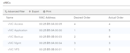
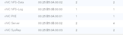
![]() Take note of the MAC Address of the HANA-Admin vNIC “00:25:B5:00:0A:03”
Take note of the MAC Address of the HANA-Admin vNIC “00:25:B5:00:0A:03”
By comparing the MAC Address on the OS and Cisco UCS, eth8 on OS will carry the VLAN for HANA-Admin.
10. Assigning the IP addresses and a logical name to the network interfaces:
nmcli con add con-name Access ifname enp13s0 type ethernet ip4 10.1.1.101/24
nmcli con add con-name Mgmt ifname enp8s0 type ethernet ip4 192.168.76.101/24
nmcli con add con-name NFS-Log ifname enp136s0 type ethernet ip4 192.168.228.101/24
nmcli con add con-name NFS-Data ifname enp7s0 type ethernet ip4 192.168.201.101/24
nmcli con add con-name Server ifname enp143s0 type ethernet ip4 192.168.220.101/24
This is the minimum result of the previous step:
nmcli con show
NAME UUID TYPE DEVICE
Mgmt c9202004-4028-4ebb-ab35-3f26f5b72552 802-3-ethernet enp8s0
Access 9281ea84-29f2-470f-850d-277a4d0b093e 802-3-ethernet enp13s0
enp6s0 2cd9906a-2799-4474-ba20-ee1739530feb 802-3-ethernet enp6s0
Server 5f62f2e7-7ed4-4f52-b9a1-a24c8b6775d8 802-3-ethernet enp143s0
NFS-Data 07f2e7d4-dc0d-4d1e-8f8b-6b07a5c8b70a 802-3-ethernet enp7s0
NFS-Log 98cad13d-aa18-4299-a957-ba619f887f48 802-3-ethernet enp136s0
11. Disable IPv6 – remove those six lines out of each ifcfg config file:
IPV6INIT=yes
IPV6_AUTOCONF=yes
IPV6_DEFROUTE=yes
IPV6_FAILURE_FATAL=nos
IPV6_PEERDNS=yes
IPV6_PEERROUTES=yes
12. Add the default gateway:
nmcli con modify Access ipv4.gateway "10.1.1.1"
nmcli con reload Access
13. grub update to add the HANA specific settings:
grubby –-args=”intel_idle.max_cstate=1 processor.max_cstate=1 numa_balancing=disable transparent_hugepage=never” –-update-kernel /boot/vmlinuz-3.10.0-327.el7.x86_64
Network Time
It is very important that the time on all components used for SAP HANA is in sync. The configuration of NTP is important and to be done on all systems.
vi /etc/ntp.conf
server <NTP-SERVER1 IP>
server <NTP-SERVER2 IP>
systemctl enable ntpd
systemctl start ntpd
ntpdate ntp.example.com
DNS
The Domain Name Service configuration must be done based on the local requirements.
Configuration Example
1. Add DNS IP if it is required to access internet:
vi /etc/resolv.conf
DNS1=<<IP of DNS Server1>>
DNS2=<<IP of DNS Server2>>
DOMAIN= <<Domain_name>>
2. For scale-out system, all nodes should be able to resolve Internal network IP address. Below is an example of 8 node host file with all the network defined in the /etc/hosts file:
cat /etc/hosts
127.0.0.1 localhost localhost.localdomain localhost4 localhost4.localdomain4
##
## DMZ
##
173.36.215.107 m200-cimc
173.36.215.108 isr2911
173.36.215.109 mgmtsrv01.ciscolab.local mgmtsrv01
173.36.215.110 w2k-jumpbox
173.36.215.113 esxi
##
#Admin Interface
##
192.168.76.6 linux-jumpbox-a linux-jumpbox-a
192.168.76.2 n9ka
192.168.76.3 n9kb
192.168.76.11 a300-a-sp
192.168.76.12 a300-b-sp
192.168.76.13 a300-a
192.168.76.14 a300-b
192.168.76.15 a300
192.168.76.101 server01m
192.168.76.102 server02m
192.168.76.103 server03m
192.168.76.104 server04m
192.168.76.105 server05m
192.168.76.106 server06m
192.168.76.107 server07m
192.168.76.108 server08m
192.168.76.109 server09m
192.168.76.110 server10m
192.168.76.111 server11m
192.168.76.112 server12m
##
## Access LAN
##
10.1.1.101 server01.ciscolab.local server01
10.1.1.102 server02.ciscolab.local server02
10.1.1.103 server03.ciscolab.local server03
10.1.1.104 server04.ciscolab.local server04
10.1.1.105 server05.ciscolab.local server05
10.1.1.106 server06.ciscolab.local server06
10.1.1.107 server07.ciscolab.local server07
10.1.1.108 server08.ciscolab.local server08
10.1.1.109 server09.ciscolab.local server09
10.1.1.110 server10.ciscolab.local server10
10.1.1.111 server11.ciscolab.local server11
10.1.1.112 server12.ciscolab.local server12
##
## PXE Boot
##
192.168.127.2 nx9-a-pxe
192.168.127.3 nx9-b-pxe
192.168.127.6 mgmtsrv01p
192.168.127.7 w2k-pxe
192.168.127.11 lif-pxe-1
192.168.127.12 lif-pxe-2
192.168.127.101 server01p
192.168.127.102 server02p
192.168.127.103 server03p
192.168.127.104 server04p
192.168.127.105 server05p
192.168.127.106 server06p
192.168.127.107 server07p
192.168.127.108 server08p
192.168.127.109 server09p
192.168.127.110 server10p
192.168.127.111 server11p
192.168.127.112 server12p
##
## Log LAN
##
192.168.228.11 log-01
192.168.228.12 log-02
192.168.228.101 server01l
192.168.228.102 server02l
192.168.228.103 server03l
192.168.228.104 server04l
192.168.228.105 server05l
192.168.228.106 server06l
192.168.228.107 server07l
192.168.228.108 server08l
192.168.228.109 server09l
192.168.228.110 server10l
192.168.228.111 server11l
192.168.228.112 server12l
192.168.228.102 server02l
##
## Data LAN
##
192.168.201.11 data-01
192.168.201.12 data-02
192.168.201.101 server01d
192.168.201.102 server02d
192.168.201.103 server03d
192.168.201.104 server04d
192.168.201.105 server05d
192.168.201.106 server06d
192.168.201.107 server07d
192.168.201.108 server08d
192.168.201.109 server09d
192.168.201.110 server10d
192.168.201.111 server11d
192.168.201.112 server12d
##
## Server LAN
##
192.168.220.101 server01s
192.168.220.102 server02s
192.168.220.103 server03s
192.168.220.104 server04s
192.168.220.105 server05s
192.168.220.106 server06s
192.168.220.107 server07s
192.168.220.108 server08s
192.168.220.109 server09s
192.168.220.110 server10s
192.168.220.111 server11s
192.168.220.112 server12s
##
## IPMI Address
##
172.25.186.141 cishana01-ipmi
172.25.186.142 cishana02-ipmi
172.25.186.143 cishana03-ipmi
172.25.186.144 cishana04-ipmi
172.25.186.145 cishana05-ipmi
172.25.186.146 cishana06-ipmi
172.25.186.147 cishana07-ipmi
172.25.186.148 cishana08-ipmi
SSH Keys
The SSH Keys must be exchanged between all nodes in a SAP HANA Scale-Out system for user ‘root’ and user <SID>adm.
1. Generate the rsa public key by executing the command ssh-keygen -b 2048
ssh-keygen -b 2048
Generating public/private rsa key pair.
Enter file in which to save the key (/root/.ssh/id_rsa):
Enter passphrase (empty for no passphrase):
Enter same passphrase again:
Your identification has been saved in /root/.ssh/id_rsa.
Your public key has been saved in /root/.ssh/id_rsa.pub.
The key fingerprint is:
14:5a:e6:d6:00:f3:81:86:38:47:e7:fb:de:78:f5:26 root@server01.ciscolab.local
The key's randomart image is:
+--[ RSA 2048]----+
| o..+o* |
| o oooB = |
| o .o = . |
| + |
| . S |
| . o. E o |
| o.. o |
+-----------------+
2. The SSH Keys must be exchanged between all nodes in a SAP HANA Scale-Out system for user ‘root’ and user.
3. Exchange the rsa public key by executing the below command from First server to rest of the servers in the scale-out system.
“ssh-copy-id -i /root/.ssh/id_rsa.pub server02”
ssh-copy-id -i /root/.ssh/id_rsa.pub server02
The authenticity of host 'server02 (172.29.220.202)' can't be established.
RSA key fingerprint is 28:5c:1e:aa:04:59:da:99:70:bc:f1:d1:2d:a4:e9:ee.
Are you sure you want to continue connecting (yes/no)? yes
Warning: Permanently added 'server02,172.29.220.202' (RSA) to the list of known hosts.
root@server02's password:
Now try logging into the machine, with "ssh 'server02'", and check in:
.ssh/authorized_keys
to make sure we haven't added extra keys that you weren't expecting.
4. Repeat steps 1- 4 for all the servers in the single SID SAP HANA system
Storage for SAP HANA
Virtualized SAP HANA (vHANA)
ESXi Host Installation
The IP KVM enables the administrator to begin the installation of the operating system (OS) through remote media. It is necessary to log in to the Cisco UCS environment to run the IP KVM.
To log in to the Cisco UCS environment, complete the following steps:
1. Open a web browser and enter the IP address for the Cisco UCS cluster address. This step launches the Cisco UCS Manager application.
2. Log in to Cisco UCS Manager by using the admin user name and password.
3. From the main menu, click the Servers tab.
4. Select Servers > Service Profiles > root > Sub-Organization > vHANA> vHANA-Host-01.
5. Right-click vHANA-Host-01.and select KVM Console.
Set Up VMware ESXi Installation
1. Download Cisco Custom Image for ESXi 6.5.0 U1.
2. Click the following link vmware login page.
3. Type your email or customer number and the password and then click Log in.
4. Click on the following link CiscoCustomImage ESXi 6.5GA.
5. Click Download.
6. Save it to your destination folder.
To prepare the server for the OS installation, complete the following steps on each ESXi host:
1. In the KVM window, click the Virtual Media tab.
2. Click Add Image.
3. Browse to the ESXi installer ISO image file and click Open.
4. Download VMware-VMvisor-Installer-201701001-4887370.x86_64.iso
5. Select the Mapped checkbox to map the newly added image.
6. Click the KVM tab to monitor the server boot.
7. Boot the server by selecting Boot Server and clicking OK, then click OK again.
Install ESXi
ESXi Hosts vHANA Host for iSCSI boot
To install VMware ESXi to the SAN-bootable LUN of the hosts, complete the following steps on each host:
1. On reboot, the machine detects the presence of the ESXi installation media. Select the ESXi installer from the menu that is displayed.
2. After the installer is finished loading, press Enter to continue with the installation.
3. Read and accept the end-user license agreement (EULA). Press F11 to accept and continue.
4. Select the NetApp LUN that was previously set up as the installation disk for ESXi and press Enter to continue with the installation.
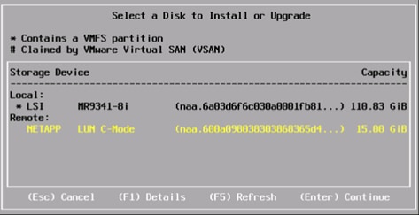
5. Select the appropriate keyboard layout and press Enter.
6. Enter and confirm the root password and press Enter.
7. The installer issues a warning that existing partitions will be removed from the volume. Press F11 to continue with the installation.
8. After the installation is complete, clear the Mapped checkbox (located in the Virtual Media tab of the KVM console) to unmap the ESXi installation image.
![]() The ESXi installation image must be unmapped to make sure that the server reboots into ESXi and not into the installer.
The ESXi installation image must be unmapped to make sure that the server reboots into ESXi and not into the installer.
9. The Virtual Media window might issue a warning stating that it is preferable to eject the media from the guest. Because the media cannot be ejected and it is read-only, simply click Yes to unmap the image.
10. From the KVM tab, press Enter to reboot the server.
Set Up Management Networking for ESXi Hosts
Adding a management network for each VMware host is necessary for managing the host.
To configure the vHANA-Host-01 ESXi host with access to the management network, complete the following steps:
1. After the server has finished rebooting, press F2 to customize the system.
2. Log in as root and enter the corresponding password.
3. Select the Configure the Management Network option and press Enter.
4. Select the Network Adapters and press Enter
5. Select the Devices under Device Name, which are used for Management Network, by matching the MAC address from the Cisco UCS Service Profile. Press Enter.
To get the MAC address from Cisco UCS Service Profile, complete the following steps:
1. In Cisco UCS Manager, click the Servers tab in the navigation pane
2. Select Servers > Service Profiles > root > Sub-Organization > vHANA> vHANA-01.
3. Expand by clicking on +
4. Click on vNICs
5. On the Right pane list of the vNICs with MAC Address are listed.
![]() Take note of the MAC Address of the vNIC vHANA_A and vNIC vHANA_B.
Take note of the MAC Address of the vNIC vHANA_A and vNIC vHANA_B.
6. Select the VLAN (Optional) option and press Enter.
7. Enter the <<var_vhana_esx_mgmt_vlan_id>> and press Enter.
8. From the Configure Management Network menu, select IP Configuration and press Enter.
9. Select the Set Static IP Address and Network Configuration option by using the space bar.
10. Enter the IP address for managing the first ESXi host: <<var_vhana_host_mgmt_01_ip>>.
11. Enter the subnet mask for the first ESXi host.
12. Enter the default gateway for the first ESXi host.
13. Press Enter to accept the changes to the IP configuration.
14. Select the IPv6 Configuration option and press Enter.
15. Using the spacebar, unselect Enable IPv6 (restart required) and press Enter.
16. Select the DNS Configuration option and press Enter.
![]() Since the IP address is assigned manually, the DNS information must also be entered manually.
Since the IP address is assigned manually, the DNS information must also be entered manually.
17. Enter the IP address of the primary DNS server.
18. Optional: Enter the IP address of the secondary DNS server.
19. Enter the fully qualified domain name (FQDN) for the first ESXi host.
20. Press Enter to accept the changes to the DNS configuration.
21. Press Esc to exit the Configure Management Network submenu.
22. Press Y to confirm the changes and return to the main menu.
23. The ESXi host reboots. After reboot, press F2 and log back in as root.
24. Select Test Management Network to verify that the management network is set up correctly and press Enter.
25. Press Enter to run the test.
26. Press Enter to exit the window.
27. Press Esc to log out of the VMware console.
Log in to VMware ESXi Hosts Using a HTML5 Browser
ESXi Host vHANA-Host-01
To log in to the vHANA-Host-01 ESXi host by using a html5 Web browser, complete the following steps:
1. Enter the IP address of vHANA-Host-01 in the browser address line: <<var_vhana_host_mgmt_01_ip>>.
2. Enter root for the user name.
3. Enter the root password.
4. Click Login to connect.
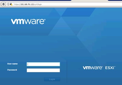
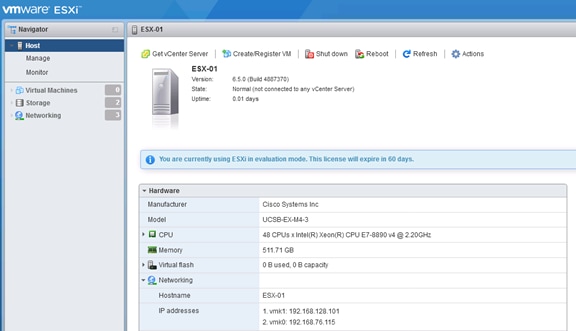
Install the ESXi License Key
There are no additional features required for the Management ESX server. If you will use this ESX server as a standalone server, the free ESXi license is sufficient.
To install the ESXi license, complete the following steps:
1. Select Manage in the Navigator pane.
2. Select Licensing in the Manage pane.
3. Select Assign License to install the ESXi license.
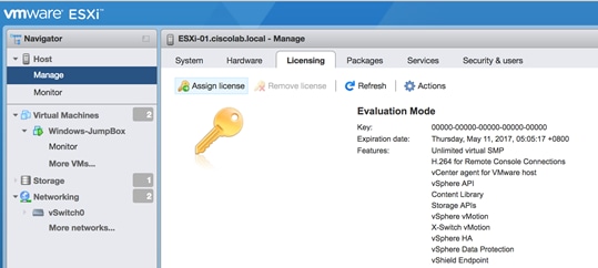
Post Install Configuration
To configure the ESXi as per SAP HANA requirement, complete the following steps:
1. Select Manage in the Navigator pane.
2. Select Hardware in the Manage pane.
3. Select Power Management.
4. Select Change Policy.
5. Under Power Management Policy choose High performance.
6. Click OK.
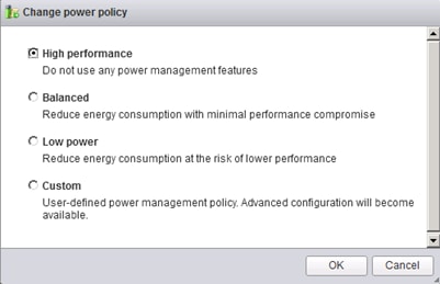
To configure the host to activate the host accessor functions, complete the following steps:
1. Select the Manage in the Navigator pane.
2. Click the System tab.
3. Click Advanced Settings in the System pane
4. Scroll down to "Misc.GuestLibAllowHostInfo".
5. Set the value to "1".
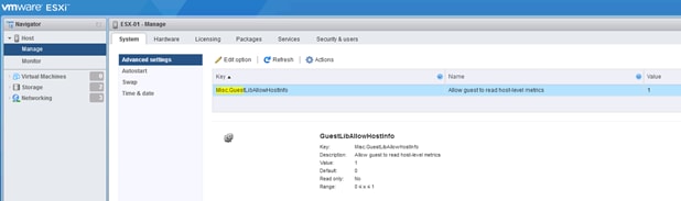
Set Up VMkernel Ports and Virtual Switch
ESXi vHANA Host Network Configuration for Management
To set up the VMkernel ports and the virtual switches on the vHANA-01 ESXi host, complete the following steps:
1. From the ESX Navigator pane select Networking.
2. Click the Virtual Switches tab.
3. Select vSwitch0.
4. Click Edit Settings on the right side of vSwitch0.
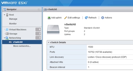
5. Select the vSwitch configuration and click Edit.
6. From the General tab, change the MTU to 9000.
7. Click OK to close the properties for vSwitch0.
8. Configure the iSCSIBootvSwitch
9. From the ESX Navigator pane select Networking.
10. Click the Virtual Switches tab.
11. Select iSCSIBootvSwitch
12. Click Edit Settings on the right side of iSCSIBootvSwitch.
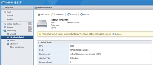
13. Select the vSwitch configuration and click Edit.
14. From the General tab, change the MTU to 9000.
15. Click OK to close the properties for iSCSIBootvSwitch.
16. Create a new vSwitch for iSCSI redundancy.
17. Select Networking from the Navigator pane.
18. Select vSwitches.
19. Select Add standard virtual switch.
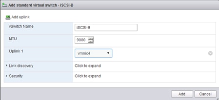
20. From the ESX Navigator pane select Networking.
21. Click the Port Groups tab.
22. Select Add Port Group
23. Name the Port Group iSCSIBootPG-2
24. Add VLAN information to the PG 129
25. Select the vSwitch for the PC.
26. Click Add to create the PG
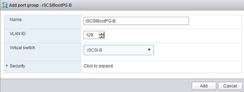
27. Add the additional iSCSI NIC to the ESXi Host
28. From the ESX Navigator pane select Networking.
29. Click VMKernel NIC tab.
30. Select Add VMKernelNIC.
31. Name the Port Group iSCSIBootPG-2.
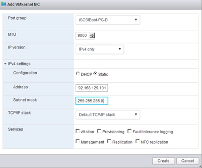
The Network Configuration is shown below:
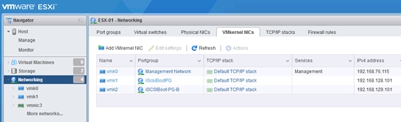
32. Add ESX Management Network vSwitch ESX_Management.
33. From the ESX Navigator pane select Networking.
34. Click the Virtual Switches tab.
35. Select Add standart Virtual Switch
36. Name of the vSwitch ESX_Management.
37. Change the MTU to 9000.
38. Select vmnic1.
39. Click Add to create the vSwitch.
40. Add an redundant NIC to the vSwitch.
41. Select Add Uplinks.
42. Select vmnic2 and select Failover NIC.
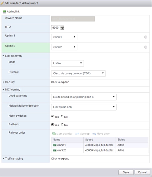
43. From the ESX Navigator pane select Networking.
44. Click the Port Groups tab.
45. Select Add Port Group.
46. Select the name of the PG vMotion.
47. Change the MTU to 9000 and select vMotion.
48. Select VLAN 3112.
49. Select vSwitch ESX_Management.
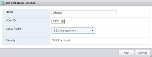
50. From the ESX Navigator pane select Networking.
51. Click the Port Groups tab.
52. Select Add Port Group.
53. Select the name of the PG ESX_NFS.
54. Select VLAN 130.
55. Select vSwitch ESX_Management.
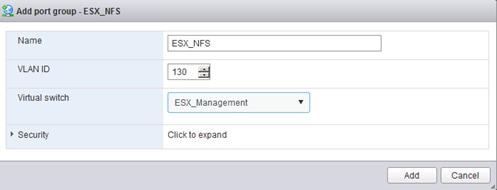
56. From the ESX Navigator pane select Networking.
57. Click the Port Groups tab.
58. Select Add Port Group.
59. Select the name of the PG ESX_Management.
60. Select VLAN 3111.
61. Select vSwitch ESX_Management.
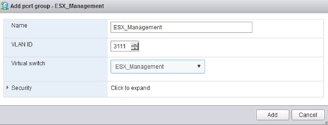
62. From the ESX Navigator pane select Networking.
63. Click the VMKernel NIC tab.
64. Select Add VMKernel NIC.
65. Select the name of the PG vMotion.
66. Change the MTU to 9000 and select vMotion.
67. IP Address 192.168.250.101 / Netmask 255.255.255.0
68. Select Services vMotion.
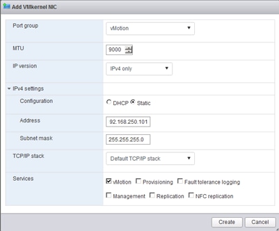
69. From the ESX Navigator pane select Networking.
70. Click the VMKernel NIC tab.
71. Select Add VMKernel NIC.
72. Select the name of the PG ESX_NFS.
73. Change the MTU to 9000 and select vMotion.
74. IP Address 192.168.130.201 / Netmask 255.255.255.0
75. Select Services Management.
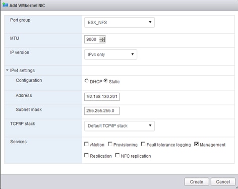
76. Click OK to finalize the edits for the VMkernel-vMotion network.
77. Close the dialog box to finalize the ESXi host networking setup.
The networking for the ESXi host should be similar to the following example:
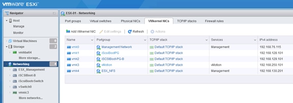
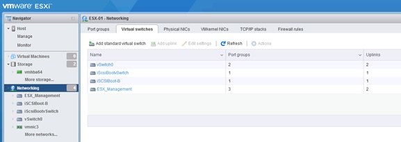
78. ISCSI Failover configuration. Add all three additional iSCSI interfaces to the iSCSI Configuration
79. Click Storage in the Navigator pane.
80. Select the Adapters.
81. Select Configure iSCSI.
82. Select Add Static Target.
83. Insert the IQN name from the iSCSI SVM iqn.1992-08.com.netapp:sn.35084cc1105511e7983400a098aa4cc7:vs.4
84. Insert the IP address of the SVM 192.168.128.11.
85. Repeat this for the other two iSCSI paths.
86. Press Save Configuration to store the iSCSI configuration
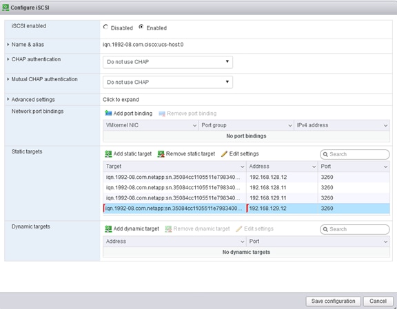
ESXi vHANA Host Network Configuration for vHANA Virtual Machines
To create the four necessary Port Groups for vHANA, complete the following steps:
1. From VMware vSphere client, select the Networking pane.
2. Click Port Groups.
3. Click Add Port Group.
4. Name the Port Group NFS_Data.
5. Select vSwitch0 to bind the Port Group to the vSwitch.
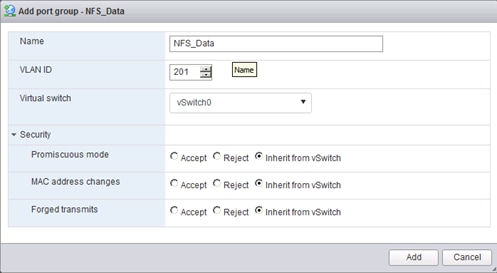
6. Click Next and Click Finish to add for VM Network.
7. Repeat this step for NFS_Log and NFS_Backup and Access/
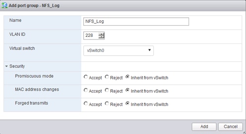
The Port Group configuration NFS_Backup is shown below:
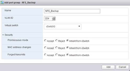
The Port Group Access is shown below:
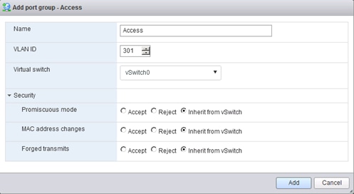
The configuration after all Port Groups are created is shown below:
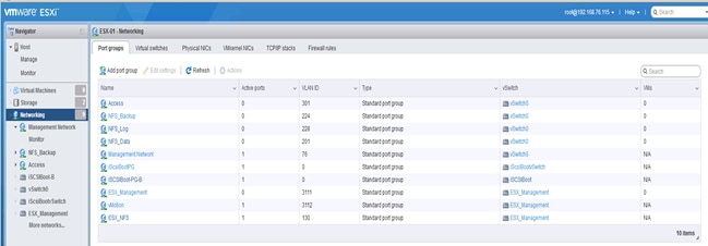
Mount Datastores
Mount the NFS datastores for Virtual Machines.
ESXi Hosts Virtualized SAP HANA (vHANA)-Host-01
To mount the required datastores, complete the following steps on each ESXi host:
1. From VMware vSphere client, select the host in the inventory.
2. Click the Configuration tab to enable configurations.
3. Click Storage in the Hardware pane.
4. From the Datastore area, click Add Storage to open the Add Storage wizard.
5. Select Network File System and click Next.
6. The wizard prompts for the location of the NFS export. Enter <<var_node01_esx_lif_ip>> as the IP address for NFS server.
7. Make sure that the Mount NFS read only checkbox is NOT selected.
8. Enter vhana_datastore_1 as the datastore name.
9. Click Next to continue with the NFS datastore creation.
10. Click Finish to finalize the creation of the NFS datastore.
Configure NTP on ESXi Hosts
ESXi Hosts vHANA-Host-01
To configure Network Time Protocol (NTP) on the ESXi hosts, complete the following steps on each host:
1. From each VMware vSphere client, select the host in the inventory.
2. Click the Configuration tab to enable configurations.
3. Click Time Configuration in the Software pane.
4. Click Properties at the upper right side of the window.
5. At the bottom of the Time Configuration dialog box, click Options.
6. In the NTP Daemon Options dialog box, complete the following steps:
a. Click General in the left pane and select Start and stop with host.
b. Click NTP Settings in the left pane and click Add.
7. In the Add NTP Server dialog box, enter <<var_global_ntp_server_ip>> as the IP address of the NTP server and click OK.
8. In the NTP Daemon Options dialog box, select the Restart NTP Service to Apply Changes checkbox and click OK.
9. In the Time Configuration dialog box, complete the following steps:
a. Select the NTP Client Enabled checkbox and click OK.
b. Verify that the clock is now set to the correct time.
![]() The NTP server time may vary slightly from the host time.
The NTP server time may vary slightly from the host time.
Storage Configuration
Complete Configuration Worksheet
Before running the setup script, complete the cluster setup worksheet in the ONTAP 9.2 Software Setup Guide located in the NetApp® ONTAP® 9 Documentation Center.
Configure ONTAP Nodes
Before running the setup script, review the configuration worksheets in the ONTAP 9.2 Software Setup Guide to learn about configuring ONTAP software. Table 20 lists the information needed to configure two ONTAP nodes. Customize the cluster detail values with the information applicable to your deployment.
Table 20 ONTAP Software Installation Prerequisites
| Cluster Detail |
Cluster Detail Value |
| Cluster node 01 IP address |
<node01-mgmt-ip> |
| Cluster node 01 netmask |
<node01-mgmt-mask> |
| Cluster node 01 gateway |
<node01-mgmt-gateway> |
| Cluster node 02 IP address |
<node02-mgmt-ip> |
| Cluster node 02 netmask |
<node02-mgmt-mask> |
| Cluster node 02 gateway |
<node02-mgmt-gateway> |
| Data ONTAP 9.1 URL |
<url-boot-software> |
Configure Node 01
To configure node 01, complete the following steps:
1. Connect to the storage system console port. You should see a Loader-A prompt. However, if the storage system is in a reboot loop, press Ctrl-C to exit the autoboot loop when the following message displays:
Starting AUTOBOOT press Ctrl-C to abort…
2. Allow the system to boot up.
autoboot
3. Press Ctrl-C when prompted.
![]() If ONTAP 9.1 is not the version of software being booted, continue with the following steps to install new software. If ONTAP 9.1 is the version of software being booted, continue with step 14.
If ONTAP 9.1 is not the version of software being booted, continue with the following steps to install new software. If ONTAP 9.1 is the version of software being booted, continue with step 14.
4. To install new software, select option 7.
5. Enter y to perform an upgrade.
6. Select e0M for the network port you want to use for the download.
7. Enter y to reboot now.
8. Enter the IP address, netmask, and default gateway for e0M.
<node01-mgmt-ip> <node01-mgmt-mask> <node01-mgmt-gateway>
9. Enter the URL where the software can be found.
![]() This web server must be pingable.
This web server must be pingable.
<url-boot-software>
10. Press Enter for the user name, indicating no user name.
11. Enter y to set the newly installed software as the default to be used for subsequent reboots.
12. Enter y to reboot the node.
![]() When installing new software, the system might perform firmware upgrades to the BIOS and adapter cards, causing reboots and possible stops at the Loader-A prompt. If these actions occur, the system might deviate from this procedure.
When installing new software, the system might perform firmware upgrades to the BIOS and adapter cards, causing reboots and possible stops at the Loader-A prompt. If these actions occur, the system might deviate from this procedure.
13. Press Ctrl-C when the following message displays:
Press Ctrl-C for Boot Menu
14. Select option 4 for Clean Configuration and Initialize All Disks.
15. Enter y to zero disks, reset config, and install a new file system.
16. Enter y to erase all the data on the disks.
![]() The initialization and creation of the root aggregate can take 90 minutes or more to complete, depending on the number and type of disks attached. When initialization is complete, the storage system reboots. Note that SSDs take considerably less time to initialize. You can continue with node 02 configuration while the disks for node 01 are zeroing.
The initialization and creation of the root aggregate can take 90 minutes or more to complete, depending on the number and type of disks attached. When initialization is complete, the storage system reboots. Note that SSDs take considerably less time to initialize. You can continue with node 02 configuration while the disks for node 01 are zeroing.
Configure Node 02
To configure node 02, complete the following steps:
1. Connect to the storage system console port. You should see a Loader-A prompt. However, if the storage system is in a reboot loop, press Ctrl-C to exit the autoboot loop when the following message displays:
Starting AUTOBOOT press Ctrl-C to abort…
2. Allow the system to boot up.
autoboot
3. Press Ctrl-C when prompted.
![]() If ONTAP 9.1 is not the version of software being booted, continue with the following steps to install new software. If ONTAP 9.1 is the version of software being booted, continue with step 14.
If ONTAP 9.1 is not the version of software being booted, continue with the following steps to install new software. If ONTAP 9.1 is the version of software being booted, continue with step 14.
4. To install new software, select option 7.
5. Enter y to perform an upgrade.
6. Select e0M for the network port you want to use for the download.
7. Enter y to reboot now.
8. Enter the IP address, netmask, and default gateway for e0M.
<node02-mgmt-ip> <node02-mgmt-mask> <node02-mgmt-gateway>
9. Enter the URL where the software can be found.
![]() This web server must be pingable.
This web server must be pingable.
<url-boot-software>
10. Press Enter for the user name, indicating no user name.
11. Enter y to set the newly installed software as the default to be used for subsequent reboots.
12. Enter y to reboot the node.
![]() When installing new software, the system might perform firmware upgrades to the BIOS and adapter cards, causing reboots and possible stops at the Loader-A prompt. If these actions occur, the system might deviate from this procedure.
When installing new software, the system might perform firmware upgrades to the BIOS and adapter cards, causing reboots and possible stops at the Loader-A prompt. If these actions occur, the system might deviate from this procedure.
13. Press Ctrl-C when you see this message:
Press Ctrl-C for Boot Menu
14. Select option 4 for Clean Configuration and Initialize All Disks.
15. Enter y to zero disks, reset config, and install a new file system.
16. Enter y to erase all the data on the disks.
![]() The initialization and creation of the root aggregate can take 90 minutes or more to complete, depending on the number and type of disks attached. When initialization is complete, the storage system reboots. Note that SSDs take considerably less time to initialize.
The initialization and creation of the root aggregate can take 90 minutes or more to complete, depending on the number and type of disks attached. When initialization is complete, the storage system reboots. Note that SSDs take considerably less time to initialize.
Set Up Node 01
Table 21 lists all the parameters required to set up the ONTAP cluster.
Table 21 ONTAP Cluster Prerequisites
| Cluster Detail |
Cluster Detail Value |
| Cluster name |
<clustername> |
| ONTAP base license |
<cluster-base-license-key> |
| NFS license key |
<nfs-license-key> |
| iSCSI license key |
<iscsi-license-key> |
| NetApp SnapRestore® license key |
<snaprestore-license-key> |
| NetApp SnapVault® license key |
<snapvault-license-key> |
| NetApp SnapMirror® license key |
<snapmirror-license-key> |
| NetApp FlexClone® license key |
<flexclone-license-key> |
| Cluster management IP address |
<clustermgmt-ip> |
| Cluster management netmask |
<clustermgmt-mask> |
| Cluster management gateway |
<clustermgmt-gateway> |
| Cluster node 01 IP address |
<node01-mgmt-ip> |
| Cluster node 01 netmask |
<node01-mgmt-mask> |
| Cluster node 01 gateway |
<node01-mgmt-gateway> |
| Cluster node 02 IP address |
<node02-mgmt-ip> |
| Cluster node 02 netmask |
<node02-mgmt-mask> |
| Cluster node 02 gateway |
<node02-mgmt-gateway> |
| Node 01 service processor IP address |
<node01-SP-ip> |
| Node 01 service processor IP netmask |
<node01-SP-mask> |
| Node 01 service processor IP gateway |
<node01-SP-gateway> |
| Node 02 service processor IP address |
<node02-SP-ip> |
| Node 02 service processor IP netmask |
<node02-SP-mask> |
| DNS domain name |
<dns-domain-name> |
| DNS server IP address |
<dns-ip> |
| Time zone |
<timezone> |
| NTP server IP address |
<ntp-ip> |
| SNMP contact information |
<snmp-contact> |
| SNMP location |
<snmp-location> |
| DFM server or another fault management server FQDN to receive SNMP traps |
<oncommand-um-server-fqdn> |
| SNMPv1 community string |
<snmp-community> |
| Mail host to send NetApp AutoSupport® messages |
<mailhost> |
| Storage admin email for NetApp AutoSupport |
<storage-admin-email> |
From a console port program attached to the storage controller A (node 01) console port, run the node setup script. This script appears when ONTAP 9.1 software boots on the node for the first time.
17. Follow the prompts to set up node 01:
Welcome to node setup.
You can enter the following commands at any time:
"help" or "?" - if you want to have a question clarified,
"back" - if you want to change previously answered questions, and
"exit" or "quit" - if you want to quit the setup wizard.
Any changes you made before quitting will be saved.
You can return to cluster setup at any time by typing “cluster setup”.
To accept a default or omit a question, do not enter a value.
This system will send event messages and weekly reports to NetApp Technical Support.
To disable this feature, enter "autosupport modify -support disable" within 24 hours.
Enabling AutoSupport can significantly speed problem determination and resolution should a problem occur on your system.
For further information on AutoSupport, see:
http://support.netapp.com/autosupport/
Type yes to confirm and continue {yes}: yes
Enter the node management interface port [e0M]: Enter
Enter the node management interface IP address: <node01-mgmt-ip>
Enter the node management interface netmask: <node01-mgmt-mask>
Enter the node management interface default gateway: <node01-mgmt-gateway>
A node management interface on port e0M with IP address <node01-mgmt-ip> has been created
Use your web browser to complete cluster setup by accesing https://<node01-mgmt-ip>
Otherwise press Enter to complete cluster setup using the command line interface:
18. To complete the cluster setup, press Enter.
![]() Cluster setup can also be done using NetApp System Manager guided setup. This document describes the cluster setup using the CLI.
Cluster setup can also be done using NetApp System Manager guided setup. This document describes the cluster setup using the CLI.
Do you want to create a new cluster or join an existing cluster? {create, join}:
create
Do you intend for this node to be used as a single node cluster? {yes, no} [no]:
Will the cluster network be configured to use network switches? [yes]:
no
Existing cluster interface configuration found:
Port MTU IP Netmask
e0a 9000 169.254.92.173 255.255.0.0
e0b 9000 169.254.244.224 255.255.0.0
Do you want to use this configuration? {yes, no} [yes]:
Enter the cluster administrator's (username "admin") password:
Retype the password:
Step 1 of 5: Create a Cluster
You can type "back", "exit", or "help" at any question.
Enter the cluster name: <clustername>
Enter the cluster base license key: <cluster-base-license-key>
Creating cluster <clustername>
Adding nodes
Cluster <clustername> has been created.
Step 2 of 5: Add Feature License Keys
You can type "back", "exit", or "help" at any question.
Enter an additional license key []:<nfs-license-key>
NFS License was added.
Enter an additional license key []:<iscsi-license-key>
iSCSI License was added.
Enter an additional license key []:<snaprestore-license-key>
SnapRestore License was added.
Enter an additional license key []:<snapvault-license-key>
SnapVault License was added.
Enter an additional license key <flexclone-license-key>
FlexClone License was added.
Enter an additional license key []:<snapmirror-license-key>
SnapMirror License was added.
Enter an additional license key []:
Step 3 of 5: Set Up a Vserver for Cluster Administration
You can type "back", "exit", or "help" at any question.
Enter the cluster management interface port: e0c
Enter the cluster management interface IP address: <clustermgmt-ip>
Enter the cluster management interface netmask: <clustermgmt-mask>
Enter the cluster management interface default gateway: <clustermgmt-gateway>
A cluster management interface on port <clustermgmt-port> with IP address <clustermgmt-ip> has been created. You can use this address to connect to and manage the cluster.
Enter the DNS domain names: <dns-domain-name>
Step 4 of 5: Configure Storage Failover (SFO)
You can type "back", "exit", or "help" at any question.
SFO will be enabled when the partner joins the cluster.
Step 5 of 5: Set Up the Node
You can type "back", "exit", or "help" at any question.
Where is the controller located []: DataCenterA
Cluster "<clustername>" has been created.
To complete cluster setup, you must join each additional node to the cluster
by running "cluster setup" on each node.
To complete system configuration, you can use either OnCommand System Manager
or the Data ONTAP command-line interface.
To access OnCommand System Manager, point your web browser to the cluster
management IP address (https:// <clustermgmt-ip>).
To access the command-line interface, connect to the cluster management
IP address (for example, ssh admin@<clustermgmt-ip>).
Wed Mar 22 08:09:43 UTC 2017
login:
![]() The node management interface can be on the same subnet as the cluster management interface, or it can be on a different subnet. In this document, we assume that it is on the same subnet.
The node management interface can be on the same subnet as the cluster management interface, or it can be on a different subnet. In this document, we assume that it is on the same subnet.
Set Up Node 02
From a console port program attached to the storage controller B (node 02) console port, run the node setup script. This script appears when ONTAP 9.1 software boots on the node for the first time.
1. Follow the prompts to set up node 02:
Welcome to cluster setup wizard.
You can enter the following commands at any time:
"help" or "?" - if you want to have a question clarified,
"back" - if you want to change previously answered questions, and
"exit" or "quit" - if you want to quit the setup wizard.
Any changes you made before quitting will be saved.
You can return to cluster setup at any time by typing “cluster setup”.
To accept a default or omit a question, do not enter a value.
This system will send event messages and weekly reports to NetApp Technical Support.
To disable this feature, enter "autosupport modify -support disable" within 24 hours.
Enabling AutoSupport can significantly speed problem determination and resolution should a problem occur on your system.
For further information on AutoSupport, see:
http://support.netapp.com/autosupport/
Type yes to confirm and continue {yes}: yes
Enter the node management interface port [e0M]: Enter
Enter the node management interface IP address: <node02-mgmt-ip>
Enter the node management interface netmask: <node02-mgmt-mask>
Enter the node management interface default gateway: <node02-mgmt-gateway>
A node management interface on port e0M with IP address <node02-mgmt-ip> has been created
Use your web browser to complete cluster setup by accesing https://<node02-mgmt-ip>
Otherwise press Enter to complete cluster setup using the command line interface:
2. To complete cluster setup, press Enter.
This node's storage failover partner is already a member of a cluster.
Storage failover partners must be members of the same cluster.
The cluster setup wizard will default to the cluster join dialog.
Do you want to create a new cluster or join an existing cluster? {join}:
join
Existing cluster interface configuration found:
Port MTU IP Netmask
e0a 9000 169.254.135.215 255.255.0.0
e0b 9000 169.254.180.204 255.255.0.0
Do you want to use this configuration? {yes, no} [yes]: yes
Step 1 of 3: Join an Existing Cluster
You can type "back", "exit", or "help" at any question.
Enter the name of the cluster you would like to join [A300-HANA]:
Joining cluster <clustername>
Starting cluster support services
This node has joined the cluster <clustername>.
Step 2 of 3: Configure Storage Failover (SFO)
You can type "back", "exit", or "help" at any question.
SFO is enabled.
Step 3 of 3: Set Up the Node
You can type "back", "exit", or "help" at any question.
This node has been joined to cluster "<clustername>".
To complete cluster setup, you must join each additional node to the cluster
by running "cluster setup" on each node.
To complete system configuration, you can use either OnCommand System Manager
or the Data ONTAP command-line interface.
To access OnCommand System Manager, point your web browser to the cluster
management IP address (https:// <clustermgmt-ip>).
To access the command-line interface, connect to the cluster management
IP address (for example, ssh admin@<clustermgmt-ip>).
Notice: HA is configured in management.
Wed Mar 22 08:12:30 UTC 2017
login:
Log In to the Cluster
To log in to the cluster, complete the following steps:
1. Open an SSH connection to either the cluster IP or host name.
2. Log in to the admin user with the password you provided earlier.
Set Auto-Revert on Cluster Management
To set the auto-revert parameter on the cluster management interface, run the following command:
network interface modify –vserver <clustername> -lif cluster_mgmt –auto-revert true
![]() A storage virtual machine (SVM) is referred to as a Vserver (or vserver) in the GUI and CLI.
A storage virtual machine (SVM) is referred to as a Vserver (or vserver) in the GUI and CLI.
Set Up Management Broadcast Domain
By default, all network ports are included in the default broadcast domain. Network ports used for data services (for example, e0d, e1a, and e1e) should be removed from the default broadcast domain, leaving just the management network ports (e0c and e0M).
To make the changes, the following commands must be performed on each storage node. Storage nodes are named after the cluster name with an appended number. To perform this task, run the following commands:
broadcast-domain remove-ports –broadcast-domain Default –ports <clustername>-01:e0d,<clustername>-01:e1a, <clustername>-01:e1e,<clustername>-02:e0d,<clustername>-02:e1a,<clustername>-02:e1e
broadcast-domain show
Set Up Service Processor Network Interface
To assign a static IPv4 address to the service processor on each node, run the following commands:
system service-processor network modify –node <clustername>-01 -address-family IPv4 –enable true –dhcp none –ip-address <node01-sp-ip> -netmask <node01-sp-mask> -gateway <node01-sp-gateway>
system service-processor network modify –node <clustername>-02 -address-family IPv4 –enable true –dhcp none –ip-address <node02-sp-ip> -netmask <node02-sp-mask> -gateway <node02-sp-gateway>
![]() The service processor IP addresses should be in the same subnet as the node management IP addresses.
The service processor IP addresses should be in the same subnet as the node management IP addresses.
Create Aggregates
![]() Advanced Data Partitioning (ADPv2) creates a root partition and two data partitions on each SSD drive in an All Flash FAS configuration. Disk auto assign should assign one data partition to each node in an HA pair.
Advanced Data Partitioning (ADPv2) creates a root partition and two data partitions on each SSD drive in an All Flash FAS configuration. Disk auto assign should assign one data partition to each node in an HA pair.
Figure 34 Disk Partitioning ADPv2
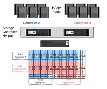
An aggregate containing the root volume for each storage controller is created during the ONTAP software setup process. To create additional aggregates, determine the aggregate name, the node on which to create it, and the number of disks it should contain.
To create new aggregates, complete the following steps:
1. Run the following commands:
aggr create -aggregate aggr01 -node <clustername>-01 -diskcount 23
aggr create -aggregate aggr02 -node <clustername>-02 -diskcount 23
![]() Use all disks except for one spare (23) to create the aggregates.
Use all disks except for one spare (23) to create the aggregates.
![]() The aggregate cannot be created until disk zeroing completes. Run the aggr show command to display aggregate creation status. Do not proceed until both aggr01 and aggr02 are online.
The aggregate cannot be created until disk zeroing completes. Run the aggr show command to display aggregate creation status. Do not proceed until both aggr01 and aggr02 are online.
2. (Optional) Rename the root aggregate on node 01 to match the naming convention for this aggregate on node 02. The aggregate is automatically renamed if system-guided setup is used.
aggr show
aggr rename –aggregate aggr0 –newname <node01-rootaggrname>
Verify Storage Failover
To confirm that storage failover is enabled, run the following commands for a failover pair:
1. Verify the status of storage failover.
storage failover show
![]() Both <clustername>-01 and <clustername>-02 must be capable of performing a takeover. Continue with step 3 if the nodes are capable of performing a takeover.
Both <clustername>-01 and <clustername>-02 must be capable of performing a takeover. Continue with step 3 if the nodes are capable of performing a takeover.
2. Enable failover on one of the two nodes.
storage failover modify -node <clustername>-01 -enabled true
![]() Enabling failover on one node enables it for both nodes.
Enabling failover on one node enables it for both nodes.
3. Verify the HA status for a two-node cluster.
![]() This step is not applicable for clusters with more than two nodes.
This step is not applicable for clusters with more than two nodes.
cluster ha show
4. Continue with step 6 if high availability is configured.
5. Only enable HA mode for two-node clusters. Do not run this command for clusters with more than two nodes because it causes problems with failover.
cluster ha modify -configured true
Do you want to continue? {y|n}: y
6. Verify that hardware assist is correctly configured and, if needed, modify the partner IP address.
storage failover hwassist show
storage failover modify –hwassist-partner-ip <node02-mgmt-ip> -node <clustername>-01
storage failover modify –hwassist-partner-ip <node01-mgmt-ip> -node <clustername>-02
Disable Flow Control on 40GbE Ports
NetApp recommends disabling flow control on all the 40GbE ports that are connected to external devices. To disable flow control, complete the following steps:
1. Run the following commands to configure node 01:
network port modify -node <clustername>-01 -port e1a,e1e -flowcontrol-admin none
Warning: Changing the network port settings will cause a several second interruption in carrier.
Do you want to continue? {y|n}: y
2. Run the following commands to configure node 02:
network port modify -node <clustername>-02 -port e1a,e1e -flowcontrol-admin none
Warning: Changing the network port settings will cause a several second interruption in carrier.
Do you want to continue? {y|n}: y
network port show –fields flowcontrol-admin
Configure Network Time Protocol
To configure time synchronization on the cluster, complete the following steps:
1. Set the time zone for the cluster.
timezone <timezone>
![]() For example, in the eastern United States, the time zone is America/New_York.
For example, in the eastern United States, the time zone is America/New_York.
2. Set the date for the cluster.
date <ccyymmddhhmm.ss>
![]() The format for the date is <[Century][Year][Month][Day][Hour][Minute].[Second]> (for example, 201704041735.17).
The format for the date is <[Century][Year][Month][Day][Hour][Minute].[Second]> (for example, 201704041735.17).
3. Configure the Network Time Protocol (NTP) servers for the cluster.
cluster time-service ntp server create -server <ntp-ip>
Configure Simple Network Management Protocol
To configure the Simple Network Management Protocol (SNMP), complete the following steps:
1. Configure basic SNMP information, such as the location and contact. When polled, this information is visible as the sysLocation and sysContact variables in SNMP.
snmp contact <snmp-contact>
snmp location “<snmp-location>”
snmp init 1
options snmp.enable on
2. Configure SNMP traps to send to remote hosts, such as a DFM server or another fault management system.
snmp traphost add <oncommand-um-server-fqdn>
Configure SNMPv1 Access
To configure SNMPv1 access, set the shared, secret plain-text password (called a community):
snmp community add ro <snmp-community>
Configure AutoSupport
NetApp AutoSupport sends support summary information to NetApp through HTTPS. To configure AutoSupport, run the following command:
system node autosupport modify -node * -state enable –mail-hosts <mailhost> -transport https -support enable -noteto <storage-admin-email>
Enable Cisco Discovery Protocol
To enable the Cisco Discovery Protocol (CDP) on the NetApp storage controllers, run the following command:
node run -node * options cdpd.enable on
![]() To be effective, CDP must also be enabled on directly connected networking equipment such as switches and routers.
To be effective, CDP must also be enabled on directly connected networking equipment such as switches and routers.
Create Broadcast Domains
Figure 35 shows the physical network connection and the virtual LANs (VLANs) used for this setup.
Figure 35 LANs and Broadcast Domains
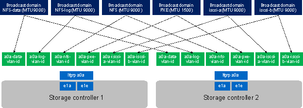
Table 22 Cluster Networking Requirements
| Cluster Detail |
Cluster Detail Value |
| NFS data VLAN ID |
<data-vlan-id> |
| NFS Log VLAN ID |
<log-vlan-id> |
| PXE VLAN ID |
<pxe-vlan-id> |
| iSCSI a VLAN ID |
<iscsi-a-vlan-id> |
| iSCSI b VLAN ID |
<iscsi-b-vlan-id> |
| NFS datastore VLAN ID |
<nfs-vlan-id> |
| Storage backend VLAN ID |
<stbackend-vlan-id> |
All broadcast domains, except for the PXE boot network, must be created with an MTU size of 9000 (jumbo frames):
broadcast-domain create -broadcast-domain NFS-data -mtu 9000
broadcast-domain create -broadcast-domain NFS-log -mtu 9000
broadcast-domain create -broadcast-domain PXE -mtu 1500
broadcast-domain create -broadcast-domain iSCSI-a -mtu 9000
broadcast-domain create -broadcast-domain iSCSI-b -mtu 9000
broadcast-domain create -broadcast-domain NFS -mtu 9000
broadcast-domain create -broadcast-domain storage-backend -mtu 9000
Create Interface Groups
To create the Link Aggregation Control Protocol (LACP) interface groups for the 40GbE data interfaces, run the following commands:
ifgrp create -node <clustername>-01 -ifgrp a0a -distr-func port -mode multimode_lacp
ifgrp add-port -node <clustername>-01 -ifgrp a0a -port e1a
ifgrp add-port -node <clustername>-01 -ifgrp a0a -port e1e
ifgrp create -node <clustername>-02 -ifgrp a0a -distr-func port -mode multimode_lacp
ifgrp add-port -node <clustername>-02 -ifgrp a0a -port e1a
ifgrp add-port -node <clustername>-02 -ifgrp a0a -port e1e
ifgrp show
Create VLANs
To create VLANs, complete the following steps:
1. Create boot VLAN ports and add them to the PXE broadcast domain.
network port modify –node <clustername>-01 -port a0a –mtu 9000
network port modify –node <clustername>-02 -port a0a –mtu 9000
network port vlan create –node <clustername>-01 -vlan-name a0a-<pxe-vlan-id>
network port vlan create –node <clustername>-02 -vlan-name a0a-<pxe-vlan-id>
broadcast-domain add-ports -broadcast-domain PXE -ports <clustername>-01:a0a-<pxe-vlan-id>, <clustername>-02:a0a-<pxe-vlan-id>
2. Create HANA data VLAN ports and add them to the NFS-Data broadcast domain.
network port vlan create –node <clustername>-01 -vlan-name a0a-<data-vlan-id>
network port vlan create –node <clustername>-02 -vlan-name a0a-<data-vlan-id>
broadcast-domain add-ports -broadcast-domain NFS-Data -ports <clustername>-01:a0a-<data-vlan-id>, <clustername>-02:a0a-<data-vlan-id>
3. Create HANA log VLAN ports and add them to the NFS-Log broadcast domain.
network port vlan create –node <clustername>-01 -vlan-name a0a-<log-vlan-id>
network port vlan create –node <clustername>-02 -vlan-name a0a-<log-vlan-id>
broadcast-domain add-ports -broadcast-domain NFS-Log -ports,<clustername>-01:a0a-<log-vlan-id>, <clustername>-02:a0a-<log-vlan-id>
4. Create the iSCSI-a VLAN ports and add them to the iSCSI-a broadcast domain.
network port vlan create –node <clustername>-01 -vlan-name a0a-<iscsi-a-vlan-id>
network port vlan create –node <clustername>-02 -vlan-name a0a-<iscsi-a-vlan-id>
broadcast-domain add-ports -broadcast-domain iSCSI-a -ports,<clustername>-01:a0a-<iscsi-a-vlan-id>, <clustername>-02:a0a-<iscsi-a-vlan-id>
5. Create the iSCSI-b VLAN ports and add them to the iSCSI-b broadcast domain.
network port vlan create –node <clustername>-01 -vlan-name a0a-<iscsi-b-vlan-id>
network port vlan create –node <clustername>-02 -vlan-name a0a-<iscsi-b-vlan-id>
broadcast-domain add-ports -broadcast-domain iSCSI-b -ports,<clustername>-01:a0a-<iscsi-b-vlan-id>, <clustername>-02:a0a-<iscsi-b-vlan-id>
6. Create NFS VLAN ports and add them to the NFS broadcast domain.
network port vlan create –node <clustername>-01 -vlan-name a0a-<nfs-vlan-id>
network port vlan create –node <clustername>-02 -vlan-name a0a-<nfs-vlan-id>
broadcast-domain add-ports -broadcast-domain NFS -ports <clustername>-01:a0a-<nfs-vlan-id>, <clustername>-02:a0a-<nfs-vlan-id>
7. Create backup VLAN ports and add them to the backup domain.
network port vlan create –node <clustername>-01 -vlan-name a0a-<backup-vlan-id>
network port vlan create –node <clustername>-02 -vlan-name a0a-<backup-vlan-id>
broadcast-domain add-ports -broadcast-domain backup -ports <clustername>-01:a0a-<backup-vlan-id>, <clustername>-02:a0a-<backup-vlan-id>
Configure SVM for the Infrastructure
Table 23 and Figure 36 describe the infrastructure SVM together with all required storage objects (volumes, export-policies, and LIFs).
Figure 36 Overview of Infrastructure SVM Components
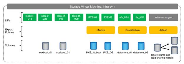
Table 23 ONTAP Software Parameters for Infrastructure SVMs
| Cluster Detail |
Cluster Detail Value |
| Infrastructure SVM management IP |
<infra-svm-ip> |
| Infrastructure SVM management IP netmask |
<infra-svm-netmask> |
| Infrastructure SVM default gateway |
<infra-svm-gateway> |
| PXE CIDR |
<pxe-cidr> |
| PXE netmask |
<pxe-netmask> |
| PXE LIF node 1 IP |
<node01-pxe_lif01-ip> |
| PXE LIF node 2 IP |
<node02-pxe_lif02-ip> |
| iSCSI a CIDR |
<iscsi-a-cidr> |
| iSCSI a Netmask |
<iscsi_a_netmask> |
| iSCSI a IP node 1 |
<node01_iscsi_lif01a_ip> |
| iSCSI a IP node 2 |
<node02_iscsi_lif02a_ip> |
| iSCSI b CIDR |
<iscsi-b-cidr> |
| iSCSI b Netmask |
<iscsi_b_netmask> |
| iSCSI b IP node 1 |
<node01_iscsi_lif01b_ip> |
| iSCSI b IP node 2 |
<node02_iscsi_lif02b_ip> |
| NFS datastore CIDR |
<nfs-CIDR> |
| NFS datastore netmask |
<nfs-netmask> |
| NFS LIF node 1 IP |
<node01-nfs_lif01-ip> |
| NFS LIF node 2 IP |
<node02-nfs_lif02-ip> |
Create SVM for the Infrastructure
To create an infrastructure SVM, complete the following steps:
1. Run the vserver create command.
vserver create –vserver infra-svm –rootvolume infra_rootvol –aggregate aggr01 –rootvolume-security-style unix
2. Select the SVM data protocols to configure, keeping iSCSI and NFS.
vserver remove-protocols –vserver infra-svm -protocols fcp,cifs,ndmp
3. Add the two data aggregates to the Infra-svm aggregate list for the NetApp Virtual Storage Console (VSC).
vserver modify –vserver infra-svm –aggr-list aggr01,aggr02
4. Enable and run the NFS protocol in the Infra-svm.
nfs create -vserver infra-svm -udp disabled
5. Turn on the SVM storage parameter for the NetApp NFS VAAI plug-in.
vserver nfs modify –vserver infra-svm –vstorage enabled
Create Load-Sharing Mirrors
To create a load-sharing mirror of an SVM root volume, complete the following steps:
1. Create a volume to be the load-sharing mirror of the infrastructure SVM root volume on each node.
volume create –vserver infra-svm –volume infra_rootvol_m01 –aggregate aggr01 –size 1GB –type DP
volume create –vserver infra-svm –volume infra_rootvol_m02 –aggregate aggr02 –size 1GB –type DP
2. Create the mirroring relationships.
snapmirror create –source-path infra-svm:infra_rootvol –destination-path
infra-svm:infra_rootvol_m01 –type LS -schedule 15min
snapmirror create –source-path infra-svm:infra_rootvol –destination-path
infra-svm:infra_rootvol_m02 –type LS -schedule 15min
3. Initialize the mirroring relationship.
snapmirror initialize-ls-set –source-path infra-svm:infra_rootvol
snapmirror show
Create Export Policies for the Root Volumes
To configure to export policies on the SVM, complete the following steps:
1. Create a new rule for the infrastructure NFS subnet in the default export policy.
vserver export-policy rule create –vserver infra-svm -policyname default –ruleindex 1 –protocol nfs -clientmatch 0.0.0.0/0 -rorule sys –rwrule sys -superuser sys –allow-suid true –anon 0
2. Assign the FlexPod® export policy to the infrastructure SVM root volume.
volume modify –vserver infra-svm –volume infra_rootvol –policy default
Add Infrastructure SVM Administrator
To add the infrastructure SVM administrator and SVM administration LIF in the out-of-band management network, complete the following steps:
1. Run the following commands:
network interface create –vserver infra-svm –lif infra-svm-mgmt –role data –data-protocol none –home-node <clustername>-02 -home-port e0c –address <infra-svm-ip> -netmask <infra-svm-mask> -status-admin up –failover-policy broadcast-domain-wide –firewall-policy mgmt –auto-revert true
![]() The SVM management IP in this step should be in the same subnet as the storage cluster management IP.
The SVM management IP in this step should be in the same subnet as the storage cluster management IP.
2. Create a default route to allow the SVM management interface to reach the outside world.
network route create –vserver infra-svm -destination 0.0.0.0/0 –gateway <infra-svm-gateway>
3. Set a password for the SVM vsadmin user and unlock the user.
security login password –username vsadmin –vserver infra-svm
Enter a new password: <password>
Enter it again: <password>
security login unlock –username vsadmin –vserver infra-svm
Create Export Policies for the Infrastructure SVM
1. Create a new export policy for the NFS datastore subnet.
vserver export-policy create -vserver infra-svm -policyname nfs-datastore
2. Create a rule for this policy.
vserver export-policy rule create -vserver infra-svm -policyname nfs-datastore -clientmatch <nfs-cidr> -rorule sys -rwrule sys -allow-suid true -allow-dev true -ruleindex 1 -anon 0 -protocol nfs -superuser sys
3. Create a new export policy for the PXE subnet.
vserver export-policy create -vserver infra-svm -policyname nfs-pxe
4. Create a rule for this policy.
vserver export-policy rule create -vserver infra-svm –policyname nfs-pxe -clientmatch <pxe-cidr> -rorule sys -rwrule sys -allow-suid true -allow-dev true -ruleindex 1 -anon 0 -protocol nfs -superuser sys
Create iSCSI LIFs
To create the four iSCSI LIFs (two on each node), run the following commands:
network interface create -vserver infra-svm -lif iscsi_lif01a -role data -data-protocol iscsi -home-node <clustername>-01 -home-port a0a-<iscsi-a-vlan-id> -address <node01_iscsi_lif01a_ip> -netmask <iscsi_a_netmask> –status-admin up –failover-policy disabled –firewall-policy data –auto-revert false
network interface create -vserver infra-svm -lif iscsi_lif01b -role data -data-protocol iscsi -home-node <clustername>-01 -home-port a0a-<iscsi-b-vlan-id> -address <node01_iscsi_lif01b_ip> -netmask <iscsi_b_netmask> –status-admin up –failover-policy disabled –firewall-policy data –auto-revert false
network interface create -vserver infra-svm -lif iscsi_lif02a -role data -data-protocol iscsi -home-node <clustername>-02 -home-port a0a-<iscsi-a-vlan-id> -address <node02_iscsi_lif02a_ip> -netmask <iscsi_a_netmask> –status-admin up –failover-policy disabled –firewall-policy data –auto-revert false
network interface create -vserver infra-svm -lif iscsi_lif02b -role data -data-protocol iscsi -home-node <clustername>-02 -home-port a0a-<iscsi-b-vlan-id> -address <node02_iscsi_lif02b_ip> -netmask <iscsi_b_netmask > –status-admin up –failover-policy disabled –firewall-policy data –auto-revert false
Create NFS LIFs
To create the NFS LIFs for the VMware datastores, run the following commands:
network interface create -vserver infra-svm -lif nfs_lif01 -role data -data-protocol nfs -home-node <clustername>-01 -home-port a0a-<nfs-vlan-id> –address <node01-nfs_lif01-ip> -netmask <nfs-netmask> -status-admin up –failover-policy broadcast-domain-wide –firewall-policy data –auto-revert true
network interface create -vserver infra-svm -lif nfs_lif02 -role data -data-protocol nfs -home-node <clustername>-02 -home-port a0a-<nfs-vlan-id> –address <node02-nfs_lif02-ip> -netmask <nfs-netmask> -status-admin up –failover-policy broadcast-domain-wide –firewall-policy data –auto-revert true
Create PXE LIFs
To create an NFS LIF for PXE boot, run the following commands:
network interface create -vserver infra-svm -lif PXE-01 -role data -data-protocol nfs -home-node <clustername>-01 -home-port a0a-<pxe-vlan-id> –address <node01-pxe_lif01-ip> -netmask <pxe-netmask> -status-admin up –failover-policy broadcast-domain-wide –firewall-policy data –auto-revert true
network interface create -vserver infra-svm -lif PXE-02 -role data -data-protocol nfs -home-node <clustername>-02 -home-port a0a-<pxe-vlan-id> –address <node02-pxe_lif02-ip> -netmask <pxe-netmask> -status-admin up –failover-policy broadcast-domain-wide –firewall-policy data –auto-revert true
Create Block Protocol (iSCSI) Service
Run the following command to create the iSCSI service. This command also starts the iSCSI service and sets the iSCSI Qualified Name (IQN) for the SVM.
iscsi create -vserver infra-svm
Create FlexVol Volumes
To create the FlexVol volumes, run the following commands:
volume create -vserver infra-svm -volume datastore_01 -aggregate aggr01 -size 500GB -state online -policy nfs-datastore -junction-path /datastore_01 -space-guarantee none -percent-snapshot-space 0
volume create -vserver infra-svm -volume datastore_02 -aggregate aggr02 -size 500GB -state online -policy nfs-datastore -junction-path /datastore_02 -space-guarantee none -percent-snapshot-space 0
volume create -vserver infra-svm -volume esxboot_01 -aggregate aggr01 -size 100GB -state online
-space-guarantee none -percent-snapshot-space 0
volume create -vserver infra-svm -volume iscsiboot_01 -aggregate aggr01 -size 100GB -state online -space-guarantee none -percent-snapshot-space 0
volume create -vserver infra-svm -volume PXE_OS -aggregate aggr02 -size 200GB -state online -policy nfs-pxe -space-guarantee none -percent-snapshot-space 0
volume modify -volume PXE_OS -files 15938348
volume create -vserver infra-svm -volume PXE_tftpboot -aggregate aggr01 -size 50GB -state online -policy nfs-pxe -space-guarantee none -percent-snapshot-space 0
snapmirror update-ls-set -source-path infra-svm:infra_rootvol
Configure LUNs for iSCSI Boot
Create Boot LUNs for ESX Servers
To create two boot LUNs, run the following commands:
lun create -vserver infra-svm -volume esxboot_01 -lun VM-Host-Infra-01 -size 15GB -ostype vmware -space-reserve disabled
lun create -vserver infra-svm -volume esxboot_01 -lun VM-Host-Infra-02 -size 15GB -ostype vmware -space-reserve disabled
Create Portset
To create a portset that includes all iSCSI LIFs, run the following commands:
portset create -vserver Infra-SVM -portset ESX_Portset -protocol iscsi -port-name iscsi_lif01a,iscsi_lif01b,iscsi_lif02a,iscsi_lif02b
Create igroups
![]() Use the values listed in <See section where ESXi service profiles are configured> to get the IQN information to create the igroups.
Use the values listed in <See section where ESXi service profiles are configured> to get the IQN information to create the igroups.
To create igroups, run the following commands:
igroup create –vserver Infra-SVM –igroup VM-Host-Infra-01 –protocol iscsi –ostype vmware –initiator <vm-host-infra-01-iqn> -portset ESX_Portset
igroup create –vserver Infra-SVM –igroup VM-Host-Infra-02 –protocol iscsi –ostype vmware –initiator <vm-host-infra-02-iqn> -portset ESX_Portset
Map ESX Boot LUNs to igroups
To map ESX boot LUNs to igroups, run the following commands:
lun map –vserver Infra-SVM –volume esxi_boot –lun VM-Host-Infra-01 –igroup VM-Host-Infra-01 –lun-id 0
lun map –vserver Infra-SVM –volume esxi_boot –lun VM-Host-Infra-02 –igroup VM-Host-Infra-02 –lun-id 0
Configure SVM for HANA
Table 24 and Figure 37 describe the HANA SVM together with all the required storage objects (volumes, export-policies, and LIFs). The HANA specific data, log, and shared volumes are covered in the section Storage Provisioning for SAP HANA.
Figure 37 Overview of SAP HANA SVM Components
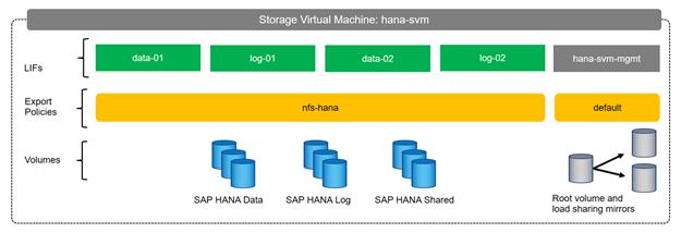
Table 24 ONTAP Software Parameter for HANA SVM
| Cluster Detail |
Cluster Detail Value |
| HANA SVM management IP |
<hana-svm-ip> |
| HANA SVM management IP netmask |
<hana-svm-netmask> |
| HANA SVM default gateway |
<hana-svm-gateway> |
| NFS Data CIDR |
<data-cidr> |
| NFS Data netmask |
<data-netmask> |
| NFS Data LIF node 1 IP |
<node01-data_lif01-ip> |
| NFS Data LIF node 2 IP |
<node02-data_lif02-ip> |
| NFS log CIDR |
<log-cidr> |
| NFS Log netmask |
<log-netmask> |
| NFS Log LIF node 1 IP |
<node01-log_lif01-ip> |
| NFS Log LIF node 2 IP |
<node02-log_lif02-ip> |
Create SVM for SAP HANA
To create an SVM for SAP HANA volumes, complete the following steps:
1. Run the vserver create command.
vserver create –vserver hana-svm –rootvolume hana_rootvol –aggregate aggr01 –rootvolume-security-style unix
2. Select the SVM data protocols to configure, keeping iSCSI and NFS.
vserver remove-protocols –vserver hana-svm -protocols fcp,cifs,ndmp
3. Add the two data aggregates to the Infra-SVM aggregate list for the NetApp VSC.
vserver modify –vserver hana-svm –aggr-list aggr01,aggr02
4. Enable and run the NFS protocol in the Infra-SVM.
nfs create -vserver hana-svm -udp disabled
5. Enable a large NFS transfer size.
set advanced
vserver nfs modify –vserver hana-svm –tcp-max-transfersize 1048576
set admin
Create Load-Sharing Mirrors
To create a load-sharing mirror of an SVM root volume, complete the following steps:
1. Create a volume to be the load-sharing mirror of the HANA SVM root volume on each node.
volume create –vserver hana-svm –volume hana_rootvol_m01 –aggregate aggr01 –size 1GB –type DP
volume create –vserver hana-svm –volume hana_rootvol_m02 –aggregate aggr02 –size 1GB –type DP
2. Create the mirroring relationships.
snapmirror create –source-path hana-svmhana_rootvol –destination-path hana-svm:hana_rootvol_m01 –type LS -schedule 15min
snapmirror create –source-path hana-svm:hana_rootvol –destination-path hana-svm:hana_rootvol_m02 –type LS -schedule 15min
3. Initialize the mirroring relationship.
snapmirror initialize-ls-set –source-path hana-svm:hana_rootvol
Create Export Policies for the Root Volumes
To configure the NFS export policies on the SVM, complete the following steps:
1. Create a new rule for the infrastructure NFS subnet in the default export policy.
vserver export-policy rule create –vserver hana-svm -policyname default –ruleindex 1 –protocol nfs -clientmatch 0.0.0.0/0 -rorule sys –rwrule sys -superuser sys –allow-suid true –anon 0
2. Assign the FlexPod export policy to the infrastructure SVM root volume.
volume modify –vserver hana-svm –volume hana_rootvol –policy default
Add HANA SVM Administrator
To add the HANA SVM administrator and SVM administration LIF in the out-of-band management network, complete the following steps:
1. Run the following commands:
network interface create –vserver hana-svm –lif hana-svm-mgmt –role data –data-protocol none –home-node <clustername>-02 -home-port e0c –address <hana-svm-ip> -netmask <hana-svm-netmask> -status-admin up –failover-policy broadcast-domain-wide –firewall-policy mgmt –auto-revert true
![]() The SVM management IP in this step should be in the same subnet as the storage cluster management IP.
The SVM management IP in this step should be in the same subnet as the storage cluster management IP.
2. Create a default route to allow the SVM management interface to reach the outside world.
network route create –vserver hana-svm -destination 0.0.0.0/0 –gateway <hana-svm-gateway>
3. Set a password for the SVM vsadmin user and unlock the user.
security login password –username vsadmin –vserver hana-svm
Enter a new password: <password>
Enter it again: <password>
security login unlock –username vsadmin –vserver hana-svm
Create Export Policies for the HANA SVM
1. Create a new export policy for the HANA data and log subnet.
vserver export-policy create -vserver hana-svm -policyname nfs-hana
2. Create a rule for this policy.
vserver export-policy rule create -vserver hana-svm -policyname nfs-hana -clientmatch <data-cidr>,<log-cidr> -rorule sys -rwrule sys -allow-suid true -allow-dev true -ruleindex 1 -anon 0 -protocol nfs -superuser sys
Create NFS LIF for SAP HANA Data
To create the NFS LIFs for SAP HANA data, run the following commands:
network interface create -vserver hana-svm -lif data-01 -role data -data-protocol nfs -home-node <clustername>-01 -home-port a0a-<data-vlan-id> –address <node01-data_lif01-ip> -netmask <data-netmask> -status-admin up –failover-policy broadcast-domain-wide –firewall-policy data –auto-revert true
network interface create -vserver hana-svm -lif data-02 -role data -data-protocol nfs -home-node <clustername>-02 -home-port a0a-<data-vlan-id> –address <node02-data_lif02-ip> -netmask <data-netmask> -status-admin up –failover-policy broadcast-domain-wide –firewall-policy data –auto-revert true
Create NFS LIF for SAP HANA Log
To create an NFS LIF for SAP HANA log, run the following commands:
network interface create -vserver hana-svm -lif log-01 -role data -data-protocol nfs -home-node <clustername>-01 -home-port a0a-<log-vlan-id> –address <node01-log_lif01-ip> -netmask <log-netmask> -status-admin up –failover-policy broadcast-domain-wide –firewall-policy data –auto-revert true
network interface create -vserver hana-svm -lif log-02 -role data -data-protocol nfs -home-node <clustername>-02 -home-port a0a-<log-vlan-id> –address <node02-log_lif02-ip> -netmask <log-netmask> -status-admin up –failover-policy broadcast-domain-wide –firewall-policy data –auto-revert true
Configure HTTPS Access
For each of the SVMs and the cluster node, create a certificate to allow secure communication with HTTPS. For each of the certificates, specify the individual values listed in Table 25.
Table 25 ONTAP Software Parameter to Enable HTTPS
| Cluster Detail |
Cluster Detail Value |
| Certificate common name |
<cert-common-name> |
| Country code |
<cert-country> |
| State |
<cert-state> |
| Locality |
<cert-locality> |
| Organization |
<cert-org> |
| Unit |
<cert-unit> |
| |
<cert-email> |
| Number of days the certificate is valid |
<cert-days> |
To configure secure access to the storage controller, complete the following steps:
1. Increase the privilege level to access the certificate commands.
set -privilege diag
Do you want to continue? {y|n}: y
2. Generally, a self-signed certificate is already in place. Verify the certificate and obtain parameters (for example the <serial-number>) by running the following command:
security certificate show
3. For each SVM shown, the certificate common name should match the DNS FQDN of the SVM. Delete the two default certificates and replace them with either self-signed certificates or certificates from a certificate authority (CA). To delete the default certificates, run the following commands:
security certificate delete -vserver hana-svm -common-name hana-svm -ca hana-svm -type server -serial <serial-number>
![]() Deleting expired certificates before creating new certificates is a best practice. Run the security certificate delete command to delete the expired certificates. In the following command, use TAB completion to select and delete each default certificate.
Deleting expired certificates before creating new certificates is a best practice. Run the security certificate delete command to delete the expired certificates. In the following command, use TAB completion to select and delete each default certificate.
4. To generate and install self-signed certificates, run the following commands as one-time commands. Generate a server certificate for the Infra-SVM, the HANA SVM, and the cluster SVM. Use TAB completion to aid in the completion of these commands.
security certificate create -common-name <cert-common-name> -type server -size 2048 -country <cert-country> -state <cert-state> -locality <cert-locality> -organization <cert-org> -unit <cert-unit> -email-addr <cert-email> -expire-days <cert-days> -protocol SSL -hash-function SHA256 -vserver hana-svm
security certificate create -common-name <cert-common-name> -type server -size 2048 -country <cert-country> -state <cert-state> -locality <cert-locality> -organization <cert-org> -unit <cert-unit> -email-addr <cert-email> -expire-days <cert-days> -protocol SSL -hash-function SHA256 -vserver infra-svm
security certificate create -common-name <cert-common-name> -type server -size 2048 -country <cert-country> -state <cert-state> -locality <cert-locality> -organization <cert-org> -unit <cert-unit> -email-addr <cert-email> -expire-days <cert-days> -protocol SSL -hash-function SHA256 -vserver <clustername>
5. To obtain the values for the parameters required in step 5 (<cert-ca> and <cert-serial>), run the security certificate show command.
6. Enable each certificate that was just created by using the –server-enabled true and –client-enabled false parameters. Use TAB completion to aid in the completion of these commands.
security ssl modify -vserver <clustername> -server-enabled true -client-enabled false -ca <cert-ca> -serial <cert-serial> -common-name <cert-common-name>
security ssl modify -vserver hana-svm -server-enabled true -client-enabled false -ca <cert-ca> -serial <cert-serial> -common-name <cert-common-name>
security ssl modify -vserver infra-svm -server-enabled true -client-enabled false -ca <cert-ca> -serial <cert-serial> -common-name <cert-common-name>
7. Disable HTTP cluster management access.
system services firewall policy delete -policy mgmt -service http –vserver <clustername>
![]() It is normal for some of these commands to return an error message stating that the entry does not exist.
It is normal for some of these commands to return an error message stating that the entry does not exist.
8. Change back to the normal admin privilege level and set up the system to allow SVM logs to be available by web.
set –privilege admin
vserver services web modify –name spi|ontapi|compat –vserver * -enabled true
Storage Provisioning for SAP HANA
This chapter describes the steps required for the storage volume configuration and the OS configuration needed to mount the storage volumes. The undelaying infrastructure configuration has already been defined in the earlier sections of this document.
The configuration steps are identical for SAP HANA running on bare metal servers and on VMware virtual machines.
Table 26 shows the required variables used in this section.
| Variable |
Value |
| IP address LIF for SAP HANA data (on storage node1) |
<node01-data_lif01-ip> |
| IP address LIF for SAP HANA data (on storage node2) |
<node02-data_lif02-ip> |
| IP address LIF for SAP HANA log (on storage node1) |
<node01-log_lif01-ip> |
| IP address LIF for SAP HANA log (on storage node2) |
<node02-log_lif02-ip> |
Each SAP HANA host, either bare metal or VMware virtual machine, has two network interfaces connected to the storage network. One network interface is used to mount the log volumes, and the second interface is used to mount the data volumes for SAP HANA. The data and log volumes of the SAP HANA systems must be distributed to the storage nodes, as shown in Figure 38, so that a maximum of six data and six log volumes are stored on a single storage node.
The limitation of having six SAP HANA hosts per storage node is only valid for production SAP HANA systems for which the storage-performance key performance indicators defined by SAP must be fulfilled. For nonproduction SAP HANA systems, the maximum number is higher and must be determined during the sizing process.
Figure 38 Distribution of SAP HANA Volumes to Storage Nodes
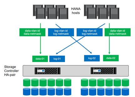
Configuring SAP HANA Single-Host Systems
Figure 2 shows the volume configuration of four single-host SAP HANA systems. The data and log volumes of each SAP HANA system are distributed to different storage controllers. For example, volume SID1_data_mnt00001 is configured on controller A, and volume SID1_log_mnt00001 is configured on controller B.
Figure 39 Volume Layout for SAP HANA Multiple Single-Host Systems
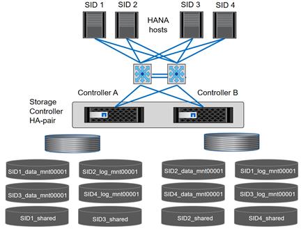
Configure a data volume, a log volume, and a volume for /hana/shared for each SAP HANA host. Table 27 shows an example configuration for single-host SAP HANA systems.
Table 27 Volume Configuration for SAP HANA Single-Host Systems
| Purpose |
Aggregate at Controller A |
Aggregate at Controller B |
| Data, log, and shared volumes for system SID1 |
· Data volume: SID1_data_mnt00001 · Shared volume: |
· Log volume: SID1_log_mnt00001 |
| Data, log, and shared volumes for system SID2 |
· Log volume: SID2_log_mnt00001 · Shared volume: |
· Data volume: SID2_data_mnt00001 |
| Data, log, and shared volumes for system SID3 |
· Data volume: SID3_data_mnt00001 |
· Log volume: SID3_log_mnt00001 · Shared volume: |
| Data, log, and shared volumes for system SID4 |
· Log volume: SID4_log_mnt00001 |
· Data volume: SID4_data_mnt00001 · Shared volume: |
Table 28 shows an example of the mount point configuration for a single-host system. To place the home directory of the sidadm user on the central storage, you should mount the /usr/sap/SID file system from the SID_shared volume.
Table 28 Mount Points for Single-Host Systems
| Junction Path |
Directory |
Mount Point at HANA Host |
| SID_data_mnt00001 |
|
/hana/data/SID/mnt00001 |
| SID_log_mnt00001 |
|
/hana/log/SID/mnt00001 |
| SID_shared |
· usr-sap · shared |
· /usr/sap/SID · /hana/shared/SID |
Configuration Example for a SAP HANA Single-Host System
The following examples show a SAP HANA database with SID=NF2 and a server RAM size of 1TB. For different server RAM sizes, the required volume sizes are different.
For a detailed description of the capacity requirements for SAP HANA, see the SAP HANA Storage Requirements white paper.
Figure 40 shows the volumes that must be created on the storage nodes and the network paths used.
Figure 40 Configuration Example for a SAP HANA Single-Host System
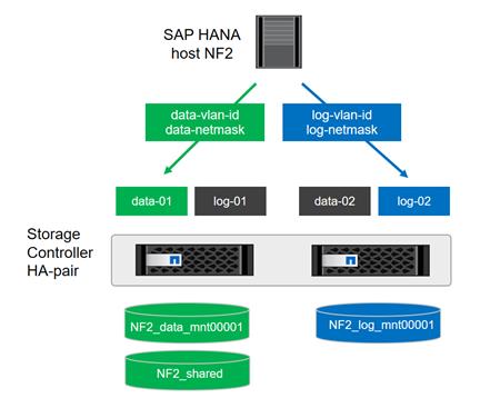
Create Data Volume and Adjust Volume Options
To create data volume and adjust the volume options, run the following commands:
volume create -vserver hana-svm -volume NF2_data_mnt00001 -aggregate aggr01 -size 1TB -state online -junction-path /NF2_data_mnt00001 -policy nfs-hana -snapshot-policy none -percent-snapshot-space 0 -space-guarantee none
vol modify -vserver hana-svm -volume NF2_data_mnt00001 -snapdir-access false
set advanced
vol modify -vserver hana-svm -volume NF2_data_mnt00001 -atime-update false
set admin
Create a Log Volume and Adjust the Volume Options
To create a log volume and adjust the volume options, run the following commands:
volume create -vserver hana-svm -volume NF2_log_mnt00001 -aggregate aggr02 -size 512GB -state online -junction-path /NF2_log_mnt00001 -policy nfs-hana -snapshot-policy none -percent-snapshot-space 0 -space-guarantee none
vol modify -vserver hana-svm -volume NF2_log_mnt00001 -snapdir-access false
set advanced
vol modify -vserver hana-svm -volume NF2_log_mnt00001 -atime-update false
set admin
Create a HANA Shared Volume and Qtrees and Adjust the Volume Options
To create a HANA shared volume and qtrees, and adjust the volume options, run the following commands:
volume create -vserver hana-svm -volume NF2_shared -aggregate aggr01 -size 1TB -state online -junction-path /NF2_shared -policy nfs-hana -snapshot-policy none -percent-snapshot-space 0 -space-guarantee none
vol modify -vserver hana-svm -volume NF2_shared -snapdir-access false
set advanced
vol modify -vserver hana-svm -volume NF2_shared -atime-update false
set admin
qtree create -vserver hana-svm -volume NF2_shared -qtree shared -security-style unix -export-policy nfs-hana
qtree create -vserver hana-svm -volume NF2_shared -qtree usr-sap -security-style unix -export-policy nfs-hana
![]() If you plan to use SAP Landscape Management, do not create the subdirectories in the NF2_shared volume as qtrees. Instead, mount the volume temporarily at the host and then create the subdirectories there.
If you plan to use SAP Landscape Management, do not create the subdirectories in the NF2_shared volume as qtrees. Instead, mount the volume temporarily at the host and then create the subdirectories there.
Update the Load-Sharing Mirror Relation
To update the load-sharing mirror relation, run the following command:
snapmirror update-ls-set -source-path hana-svmhana_rootvol
Create Mount Points
To create the required mount-point directories, take one of the following actions:
mkdir -p /hana/data/NF2/mnt00001
mkdir -p /hana/log/NF2/mnt00001
mkdir -p /hana/shared
mkdir -p /usr/sap/NF2
chmod 777 -R /hana/log/NF2
chmod 777 -R /hana/data/NF2
chmod 777 -R /hana/shared
chmod 777 -R /usr/sap/NF2
Mount File Systems
The mount options are identical for all file systems that are mounted to the host:
· /hana/data/NF2/mnt00001
· /hana/log/NF2/mnt00001
· /hana/shared
· /usr/sap/NF2
Table 29 shows the required mount options.
For NFSv3, you must switch off NFS locking to enable failover capabilities in multiple-host installations. Also, in single-host setups, NFS locking must be switched off to avoid NFS lock cleanup operations in case of a software or server failure.
With NetApp® ONTAP® 9, the NFS transfer size can be configured up to 1MB. Specifically, with 40GbE connections to the storage system, you must set the transfer size to 1MB to achieve the expected throughput values.
| Common Parameter |
NFSv3 |
NFS Transfer Size with ONTAP 9 |
| rw, bg, hard, timeo=600, intr, noatime |
vers=3, nolock |
rsize=1048576, wsize=1048576 |
To mount the file systems during system boot using the /etc/fstab configuration file, complete the following steps:
![]() The following examples show an SAP HANA database with SID=NF2 using NFSv3 and an NFS transfer size of 1MB.
The following examples show an SAP HANA database with SID=NF2 using NFSv3 and an NFS transfer size of 1MB.
1. Add the file systems to the /etc/fstab configuration file.
cat /etc/fstab
<node01-data_lif01-ip>:/NF2_data_mnt00001 /hana/data/NF2/mnt00001 nfs rw,bg,vers=3,hard,timeo=600,rsize=1048576,wsize=1048576,intr,noatime,nolock 0 0
<node02-log_lif01-ip>:/NF2_log_mnt00001 /hana/log/NF2/mnt00001 nfs rw,bg,vers=3,hard,timeo=600,rsize=1048576,wsize=1048576,intr,noatime,nolock 0 0
<node01-data_lif01-ip>:/NF2_shared/usr-sap /usr/sap/NF2 nfs rw,bg,vers=3,hard,timeo=600,rsize=1048576,wsize=1048576,intr,noatime,nolock 0 0
<node01-data_lif01-ip>:/NF2_shared/shared /hana/shared nfs rw,bg,vers=3,hard,timeo=600,rsize=1048576,wsize=1048576,intr,noatime,nolock 0 0
2. Run mount –a to mount the file systems on the host.
Configuration for SAP HANA Multiple-Host Systems
Figure 41 shows the volume configuration of a 4+1 SAP HANA system. The data and log volumes of each SAP HANA host are distributed to different storage controllers. For example, volume SID1_data1_mnt00001 is configured on controller A, and volume SID1_log1_mnt00001 is configured on controller B.
Figure 41 Volume Layout for SAP HANA Multiple-Host Systems
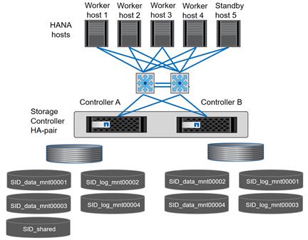
For each SAP HANA host, a data volume and a log volume are created. /hana/shared is used by all hosts of the SAP HANA system. Table 30 shows an example configuration for a multiple-host SAP HANA system with four active hosts.
Table 30 Volume Configuration for SAP HANA Multiple-Host Systems
| Purpose |
Aggregate at Controller A |
Aggregate at Controller B |
| Data and log volumes for node 1 |
Data volume: SID_data_mnt00001 |
Log volume: SID_log_mnt00001 |
| Data and log volumes for node 2 |
Log volume: SID_log_mnt00002 |
Data volume: SID_data_mnt00002 |
| Data and log volumes for node 3 |
Data volume: SID_data_mnt00003 |
Log volume: SID_log_mnt00003 |
| Data and log volumes for node 4 |
Log volume: SID_log_mnt00004 |
Data volume: SID_data_mnt00004 |
| Shared volume for all hosts |
Shared volume: SID_shared |
N/A |
Table 31 shows the configuration and mount points of a multiple-host system with four active SAP HANA hosts. To place the home directories of the sidadm user of each host on the central storage, the /usr/sap/SID file systems are mounted from the SID_shared volume.
Table 31 Mount Points for Multiple-Host Systems
| Junction Path |
Directory |
Mount Point at SAP HANA Host |
Note |
| SID_data_mnt00001 |
|
/hana/data/SID/mnt00001 |
Mounted at all hosts |
| SID_log_mnt00001 |
|
/hana/log/SID/mnt00001 |
Mounted at all hosts |
| SID_data_mnt00002 |
|
/hana/data/SID/mnt00002 |
Mounted at all hosts |
| SID_log_mnt00002 |
|
/hana/log/SID/mnt00002 |
Mounted at all hosts |
| SID_data_mnt00003 |
|
/hana/data/SID/mnt00003 |
Mounted at all hosts |
| SID_log_mnt00003 |
|
/hana/log/SID/mnt00003 |
Mounted at all hosts |
| SID_data_mnt00004 |
|
/hana/data/SID/mnt00004 |
Mounted at all hosts |
| SID_log_mnt00004 |
|
/hana/log/SID/mnt00004 |
Mounted at all hosts |
| SID_shared |
shared |
/hana/shared/SID |
Mounted at all hosts |
| SID_shared |
usr-sap-host1 |
/usr/sap/SID |
Mounted at host 1 |
| SID_shared |
usr-sap-host2 |
/usr/sap/SID |
Mounted at host 2 |
| SID_shared |
usr-sap-host3 |
/usr/sap/SID |
Mounted at host 3 |
| SID_shared |
usr-sap-host4 |
/usr/sap/SID |
Mounted at host 4 |
| SID_shared |
usr-sap-host5 |
/usr/sap/SID |
Mounted at host 5 |
Configuration Example for a SAP HANA Multiple-Host Systems
The following examples show a 2+1 SAP HANA multiple-host database with SID=NF3 and a server with a RAM size of 1TB. For different server RAM sizes, the required volume sizes are different.
For a detailed description of the capacity requirements for SAP HANA, see the SAP HANA Storage Requirements white paper.
Figure 42 shows the volumes that must be created on the storage nodes and the network paths used.
Figure 42 Configuration Example for SAP HANA Multiple-Host Systems
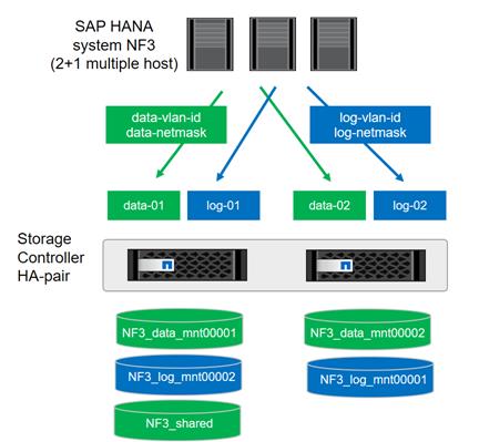
Create Data Volumes and Adjust Volume Options
To create data volumes and adjust the volume options, run the following commands:
volume create -vserver hana-svm -volume NF3_data_mnt00001 -aggregate aggr01 -size 1TB -state online -junction-path /NF3_data_mnt00001 -policy nfs-hana -snapshot-policy none -percent-snapshot-space 0 -space-guarantee none
volume create -vserver hana-svm -volume NF3_data_mnt00002 -aggregate aggr02 -size 1TB -state online -junction-path /NF3_data_mnt00002 -policy nfs-hana -snapshot-policy none -percent-snapshot-space 0 -space-guarantee none
vol modify -vserver hana-svm -volume NF3_data_mnt00001 -snapdir-access false
vol modify -vserver hana-svm -volume NF3_data_mnt00002 -snapdir-access false
set advanced
vol modify -vserver hana-svm -volume NF3_data_mnt00001 -atime-update false
vol modify -vserver hana-svm -volume NF3_data_mnt00002 -atime-update false
set admin
Create Log Volume and Adjust Volume Options
To create a log volume and adjust the volume options, run the following commands:
volume create -vserver hana-svm -volume NF3_log_mnt00001 -aggregate aggr02 -size 512GB -state online -junction-path /NF3_log_mnt00001 -policy nfs-hana -snapshot-policy none -percent-snapshot-space 0 -space-guarantee none
volume create -vserver hana-svm -volume NF3_log_mnt00002 -aggregate aggr01 -size 512GB -state online -junction-path /NF3_log_mnt00002 -policy nfs-hana -snapshot-policy none -percent-snapshot-space 0 -space-guarantee none
vol modify -vserver hana-svm -volume NF3_log_mnt00001 -snapdir-access false
vol modify -vserver hana-svm -volume NF3_log_mnt00002 -snapdir-access false
set advanced
vol modify -vserver hana-svm -volume NF3_log_mnt00001 -atime-update false
vol modify -vserver hana-svm -volume NF3_log_mnt00002 -atime-update false
set admin
Create HANA Shared Volume and Qtrees and Adjust Volume Options
To create a HANA shared volume and qtrees and adjust the volume options, run the following commands:
volume create -vserver hana-svm -volume NF3_shared -aggregate aggr01 -size 1TB -state online -junction-path /NF3_shared -policy nfs-hana -snapshot-policy none -percent-snapshot-space 0 -space-guarantee none
vol modify -vserver hana-svm -volume NF3_shared -snapdir-access false
set advanced
vol modify -vserver hana-svm -volume NF3_shared -atime-update false
set admin
qtree create -vserver hana-svm -volume NF3_shared -qtree shared -security-style unix -export-policy nfs-hana
qtree create -vserver hana-svm -volume NF3_shared -qtree usr-sap-host1 -security-style unix -export-policy nfs-hana
qtree create -vserver hana-svm -volume NF3_shared -qtree usr-sap-host2 -security-style unix -export-policy nfs-hana
qtree create -vserver hana-svm -volume NF3_shared -qtree usr-sap-host3 -security-style unix -export-policy nfs-hana
![]() If you plan to use SAP Landscape Management, do not create the subdirectories in the NF2_shared volume as qtrees. Instead, mount the volume temporarily at the host and then create the subdirectories there.
If you plan to use SAP Landscape Management, do not create the subdirectories in the NF2_shared volume as qtrees. Instead, mount the volume temporarily at the host and then create the subdirectories there.
Update Load-Sharing Mirror Relation
To update the load-sharing mirror relation, run the following command:
snapmirror update-ls-set -source-path hana-svmhana_rootvol
Create Mount Points
For a multiple-host system, create mount points and set the permissions on all worker and standby hosts.
1. Create mount points for the first worker host.
mkdir -p /hana/data/NF3/mnt00001
mkdir -p /hana/data/NF3/mnt00002
mkdir -p /hana/log/NF3/mnt00001
mkdir -p /hana/log/NF3/mnt00002
mkdir -p /hana/shared
mkdir -p /usr/sap/NF3
chmod 777 -R /hana/log/NF3
chmod 777 -R /hana/data/NF3
chmod 777 -R /hana/shared
chmod 777 -R /usr/sap/NF3
2. Create mount points for the second worker host.
mkdir -p /hana/data/NF3/mnt00001
mkdir -p /hana/data/NF3/mnt00002
mkdir -p /hana/log/NF3/mnt00001
mkdir -p /hana/log/NF3/mnt00002
mkdir -p /hana/shared
mkdir -p /usr/sap/NF3
chmod 777 -R /hana/log/NF3
chmod 777 -R /hana/data/NF3
chmod 777 -R /hana/shared
chmod 777 -R /usr/sap/NF3
3. Create mount points for the standby host.
mkdir -p /hana/data/NF3/mnt00001
mkdir -p /hana/data/NF3/mnt00002
mkdir -p /hana/log/NF3/mnt00001
mkdir -p /hana/log/NF3/mnt00002
mkdir -p /hana/shared
mkdir -p /usr/sap/NF3
chmod 777 -R /hana/log/NF3
chmod 777 -R /hana/data/NF3
chmod 777 -R /hana/shared
chmod 777 -R /usr/sap/NF3
Mount File Systems
The mount options are identical for all file systems that are mounted to the hosts:
· /hana/data/NF3/mnt00001
· /hana/data/NF3/mnt00002
· /hana/log/NF3/mnt00001
· /hana/log/NF3/mnt00002
· /hana/shared
· /usr/sap/NF3
Table 32 shows the required mount options.
For NFSv3, you must switch off NFS locking to enable failover capabilities in multiple-host installations. Also, NFS locking must be switched off in single-host setups to avoid NFS lock cleanup operations in case of a software or server failure.
With the ONTAP 9, the NFS transfer size can be configured up to 1MB. Specifically, with 40GbE connections to the storage system, you must set the transfer size to 1MB to achieve the expected throughput values.
| Common Parameter |
NFSv3 |
NFS Transfer Size with ONTAP 9 |
| rw, bg, hard, timeo=600, intr, noatime |
vers=3, nolock |
rsize=1048576, wsize=1048576 |
The following examples show a SAP HANA database with SID=NF3 using NFSv3 and an NFS transfer size of 1MB. To mount the file systems during system boot using the /etc/fstab configuration file, complete the following steps:
1. For a multiple-host system, add the required file systems to the /etc/fstab configuration file on all hosts.
![]() The /usr/sap/NF3 file system is different for each database host. The following example shows /NF3_shared/usr_sap_host1:
The /usr/sap/NF3 file system is different for each database host. The following example shows /NF3_shared/usr_sap_host1:
cat /etc/fstab
<node01-data_lif01-ip>:/NF3_data_mnt00001 /hana/data/NF3/mnt00001 nfs rw,bg,vers=3,hard,timeo=600,rsize=1048576,wsize=1048576,intr,noatime,nolock 0 0
<node02-data_lif01-ip>:/NF3_data_mnt00002 /hana/data/NF3/mnt00002 nfs rw,bg,vers=3,hard,timeo=600,rsize=1048576,wsize=1048576,intr,noatime,nolock 0 0
<node02-log_lif01-ip>:/NF3_log_mnt00001 /hana/log/NF3/mnt00001 nfs rw,bg,vers=3,hard,timeo=600,rsize=1048576,wsize=1048576,intr,noatime,nolock 0 0
<node01-log_lif01-ip>:/NF3_log_mnt00002 /hana/log/NF3/mnt00002 nfs rw,bg,vers=3,hard,timeo=600,rsize=1048576,wsize=1048576,intr,noatime,nolock 0 0
<node01-data_lif01-ip>:/NF3_shared/usr-sap-host1 /usr/sap/NF3 nfs rw,bg,vers=3,hard,timeo=600,rsize=1048576,wsize=1048576,intr,noatime,nolock 0 0
<node01-data_lif01-ip>:/NF3_shared/shared /hana/shared nfs rw,bg,vers=3,hard,timeo=600,rsize=1048576,wsize=1048576,intr,noatime,nolock 0 0
2. Run mount –a on each host to mount the file systems.
Upgrade to ONTAP 9.2
This section describes how to update your clustered storage system to ONTAP 9.2 by using NetApp OnCommand® System Manager. This upgrade is required if a newer Linux kernel or NFS client, such as RedHat RHEL 7.2, is used (which ignores the sunrpc.tcp_max_slot_table_entries system-wide setting).
This upgrade procedure is documented in more detail in the ONTAP 9 Upgrade and Revert/Downgrade Guide located in the NetApp ONTAP 9 Documentation Center.
Preparation
Before you start the upgrade, download the ONTAP 9.2 image from the NetApp Support site and store the image on a web server that can be reached by the storage system.
Upgrade by Using OnCommand System Manager
To upgrade your system by using the OnCommand System Manager, complete the following steps:
1. Log in to OnCommand System Manager using your cluster administrator credentials.
![]() You can access OnCommand System Manager by pointing your web browser to the cluster management LIF IP address.
You can access OnCommand System Manager by pointing your web browser to the cluster management LIF IP address.
2. Expand the cluster hierarchy in the left navigation pane. In the navigation pane, click Cluster Update.
3. Click Add to add the previously-downloaded ONTAP 9.2 image.
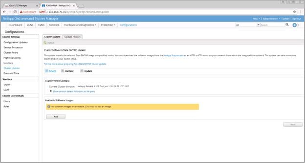
4. Enter the URL of the software image on your web server and click Add.
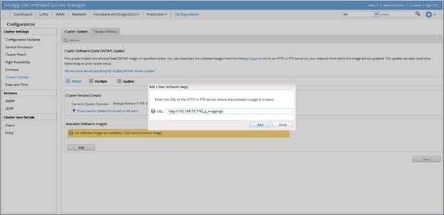
5. After the image is successfully added, click Next.
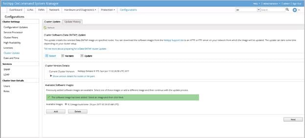
6. To validate the cluster for upgrade, click Validate.
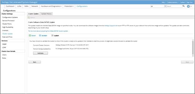
7. After the validation process is finished, verify the results, complete any required actions, and click Next.
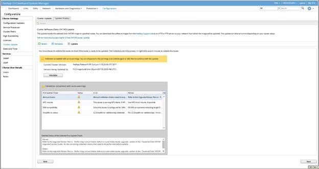
8. To update the cluster, click Update.
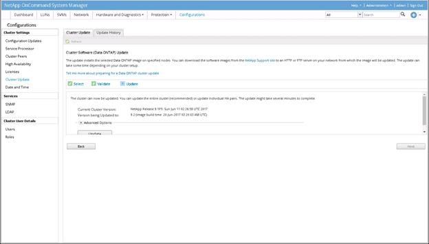
9. Click OK to confirm the LIF migration.

10. After the additional validation is finished, verify the results, complete any required actions, select the Continue Update with Warnings option, and click Continue.
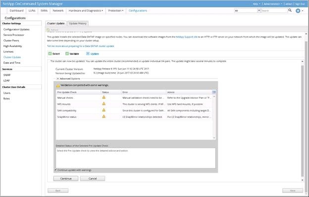
11. Verify the status of the update.
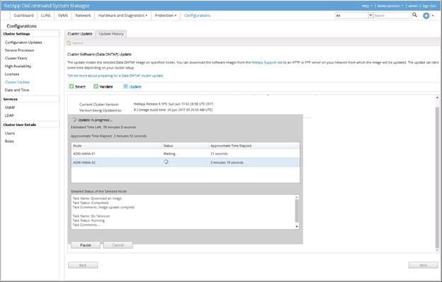
12. After the update is complete, click Finish.
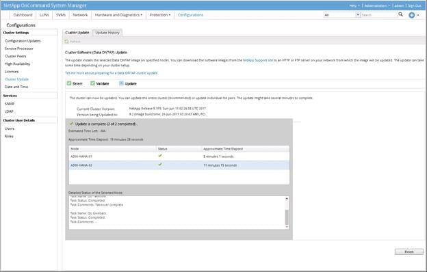
13. You will receive a confirmation screen after the update is successfully completed.
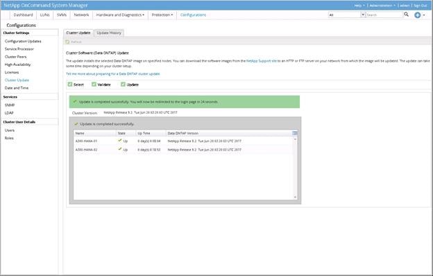
VMware vCenter 6.5
This CVD uses VMware vCenter Server 6.5 Appliance, deployed on the Cisco UCS C220 Management Server.
For the detailed installation procedure for VMware vCenter 6.5, see: http://www.cisco.com/c/en/us/td/docs/unified_computing/ucs/UCS_CVDs/flexpod_esxi65_n9fc.html
Set Up vCenter Server
vCenter Server VM
To set up vCenter Server on the vCenter Server VM, complete the following steps:
1. Using the VMware vSphere client, log in to the newly created vCenter Server as admin user.
2. Click Create a data center.
3. Enter vHANA_DC_1 as the data center name.
4. Right-click the newly created vHANA_DC_1 data center and select New Cluster.
5. Name the cluster vHANA_Cluster and select the checkboxes for Turn On VMware vSphere HA and Turn on VMware vSphere DRS. Click Next.
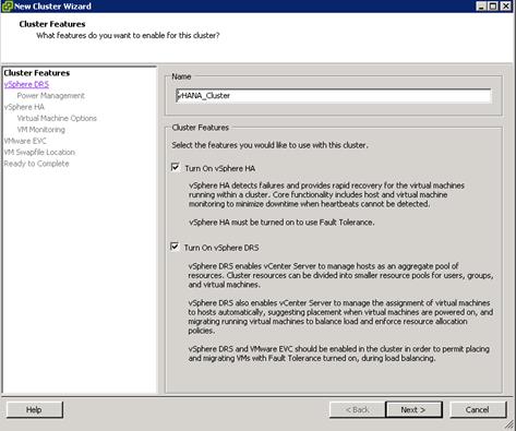
6. Accept the defaults for vSphere DRS. Click Next.
7. Accept the defaults for Power Management. Click Next.
8. Accept the defaults for vSphere HA. Click Next.
9. Accept the defaults for Virtual Machine Options. Click Next.
10. Accept the defaults for VM Monitoring. Click Next.
11. Accept the defaults for VMware EVC. Click Next.
![]() If mixing Cisco UCS B or C-Series servers within a vCenter cluster, it is necessary to enable VMware Enhanced vMotion Compatibility (EVC) mode. For more information about setting up EVC mode, refer to Enhanced vMotion Compatibility (EVC) Processor Support.
If mixing Cisco UCS B or C-Series servers within a vCenter cluster, it is necessary to enable VMware Enhanced vMotion Compatibility (EVC) mode. For more information about setting up EVC mode, refer to Enhanced vMotion Compatibility (EVC) Processor Support.
12. Select “Store the swapfile in the datastore specified by the host”. Click Next.
13. Click Finish.
14. Right-click the newly created vHANA_Cluster cluster and select Add Host.
15. In the Host field, enter either the IP address or the host name of the vHANA-Host-01 host. Enter root as the user name and the root password for this host. Click Next.
16. Click Yes.
17. Click Next.
18. Select Assign a New License Key to the Host. Click Enter Key and enter a vSphere license key. Click OK, and then click Next.
19. Click Next.
20. Click Next.
21. Click Finish. vHANA-Host-01 is added to the cluster.
22. Repeat the steps 14-21 to add vHANA-Host-02 to the cluster.
Virtual Machine for vHANA
SAP supports virtualization of SAP HANA on validated single-node SAP HANA appliances or through SAP HANA TDI verified hardware configurations. The existing SAP HANA storage requirements regarding partitioning, configuration and sizing of data, log and binary volumes remain valid.
It is important to note that a vCPU is not exactly equivalent to a full physical core because it is mapped to a logical execution thread. When hyper-threading is enabled, a physical core has two execution threads. This means, two vCPUs are needed in order to use both of them. However, the additional thread created by enabling hyper-threading does not double the performance of the core. It has been determined that enabling hyper-threading usually increases overall SAP HANA system performance by approximately 20 percent.
Refer to “SAP HANA Virtualized” for more information.
For additional information, see the Cisco UCS vHANA blog
https://blogs.sap.com/2014/06/04/sap-hana-tdi-on-cisco-ucs-and-vmware-vsphere/
For new release and SAP updates regarding vHANA, see https://launchpad.support.sap.com/#/notes/1788665/E
Create a SUSE Virtual Machine for Virtualized SAP HANA (vHANA)
Before you can start the VM installation make sure that both ESX datastores are mounted from the NetApp.
To build a virtual machine (VM) for vHANA, complete the following steps:
1. Log in as root to the ESXi web console using web browser https://<<IP_ESXi>>.
2. In the VMware vSphere web client, Click Virtual Machines and select Create/register a WM to start the wizard.
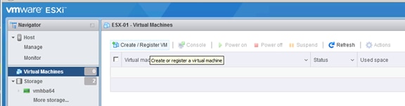
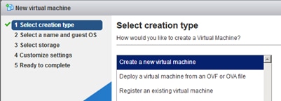
3. Click Next/
4. Specify the VM name, the OS type, and the specific OS version.
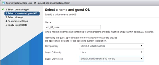
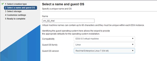
5. Select the datastore for the specific OS and click Next.
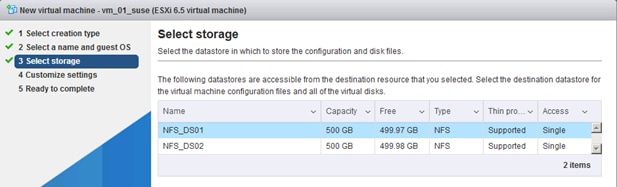
6. Specify the number of vCPU’s, the RAM, the size of for the OS, and add network adapter.
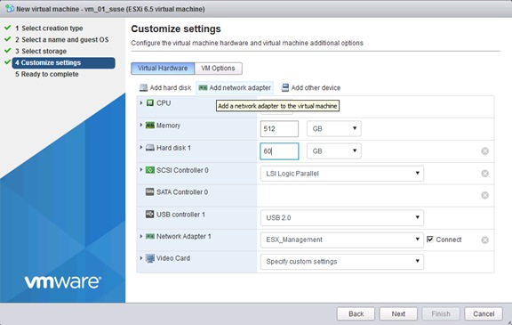
Table 33 Sizing Information for RAM and CPU
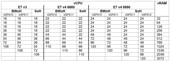
7. Add three (or more) network adapter to the VM and configure all four additional adapter as VM Network connection.
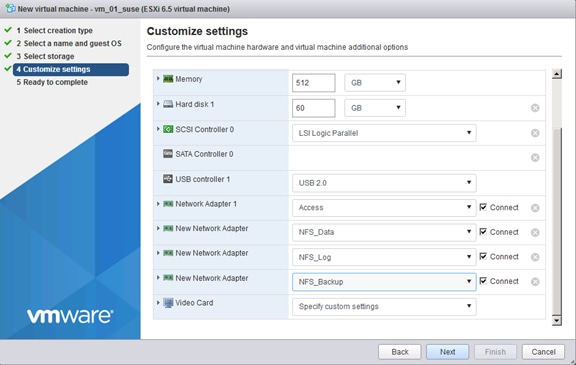
8. Network connections:
Network 1 Access
Network 2 NFS Data
Network 3 NFS Log
Network 4 NFS Backup
9. Check the parameter and click Finish to create the VM.
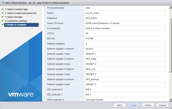
10. Click Finish to Create the Virtual Machine.
11. Configure the virtual machine to activate the accessor functions:
a. In the VMware vSphere Web Client, select the virtual machine.
b. In the menu, choose Edit Settings.
c. Choose VM Options.
d. Expand Advanced and click Edit Configuration.
e. In the Configuration Parameters window, insert the following value by clicking Add Row tools.guestlib.enableHostInfo = "TRUE" and click Save.
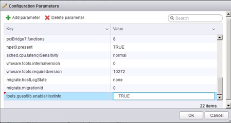
12. Disable the vNIC coalescing features to get more network throughput for the data and log NIC’s
https://www.vmware.com/content/dam/digitalmarketing/vmware/en/pdf/techpaper/vmw-tuning-latency-sensitive-workloads-white-paper.pdf
13. To do so through the vSphere Client, go to VM Settings à Options tab à Advanced General à Configuration Parameters and add an entry for ethernetX.coalescingScheme with the value of disabled (in this example the data and log NIC’s are ethernet2 and ethernet3).
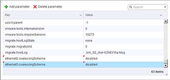
14. To make sure that the VM does not overcommit the memory please fix the settings.
15. Click the VM and choose Edit.
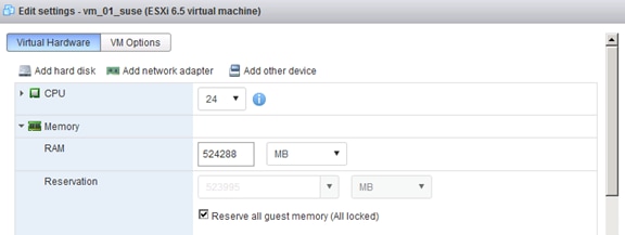
OS Installation for vHANA
To launch the console of the VM, a software component from VMware is required.
1. Download and install the plugin on the local system where the VMware web-client was opened.
2. VMware Remote Console (VMRC)10.0 tool from:
https://my.vmware.com/web/vmware/details?downloadGroup=VMRC10&productId=614
3. Log in to the web-client.
4. In the web-client, select the VM.
5. Right-click the VM created and click Open Console.
6. Click the third button (green right arrow) to power on the VM.
7. Click the ninth button (CD with a wrench) to map the Operating System ISO, and then select Connect to ISO Image on Local Disk.
8. Navigate to the ISO location, select it, and click Open.
9. For SLES : SLE-12-SP2-SAP-x86_64-GM-DVD1.iso
10. For RHEL : rhel-server-7.2-x86_64-dvd.iso
11. Click in the BIOS Setup Utility window and use the right arrow key to navigate to the Boot menu. Use the down arrow key to select CD-ROM Drive. Press the plus (+) key twice to move CD-ROM Drive to the top of the list. Press F10 and Enter to save the selection and exit the BIOS Setup Utility.
ESXi 6.5 SUSE Linux Enterprise Server 12 SP2 Installation
To install the OS on the ESX data store (NFS), complete the following steps:
![]() Refer to the SAP installation guides for SAP HANA - OS customization requirement.
Refer to the SAP installation guides for SAP HANA - OS customization requirement.
1. OS installer will start choose SLES for SAP Applications – Installation and Press Enter.
2. Leave the keyboard and system language as it is (US English).
3. Agree to the License Terms, click Next.
4. Configure the Network adapter (retrieve the MAC addresses for the VM from the ESX host).
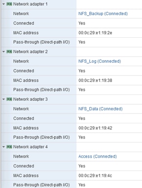
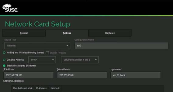
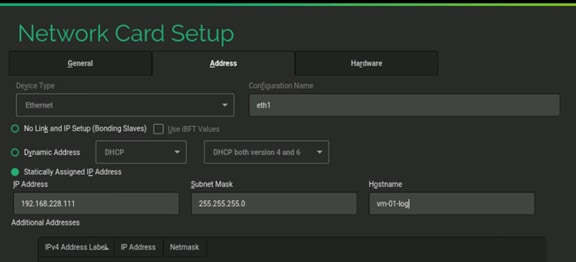
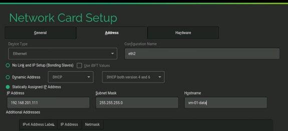
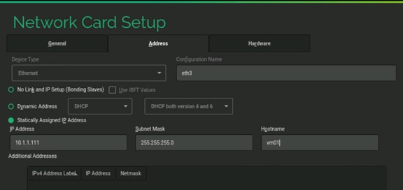
5. Make sure the network settings are correct.
6. Select the SAP version of the SUSE distribution.
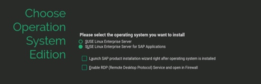
7. Do not install any additional software packages.
8. For Disk Configuration click the Expert tab.
9. Click Partitioning.
10. In the Expert Partitioner screen, select Custom Partition (for experts) and click Next.
11. In the System View, expand hard disks and select sda with 60 GB space.
12. Click Add and leave Primary Partition as selected. Click Next.
13. Choose Custom Size 100 MB. Click Next.
14. File System leave Ext3 and change the Mount Point to /boot. Click Finish.
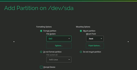
15. Click Add and leave Primary Partition as selected. Click Next.
16. Choose Custom Size 2.00 GB. Click Next.
17. Change File System swap and change the Mount Point to swap. Click Finish.
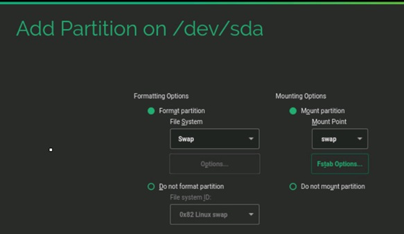
18. Click Add and leave Primary Partition as selected. Click Next.
19. Leave the Size as remaining free space. Click Next.
20. For File System, keep Ext3 and keep the Mount Point and click Finish.
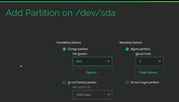
21. Click Accept.
Partition overview is shown below:
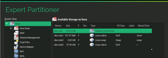
22. Select Appropriate Region and Time Zone. Click Next.
![]() The recommendation from SAP is to set the server time zone on all SAP HANA nodes to UTC. Every user configured on the system can have an “own” time zone setting to work with the local time.
The recommendation from SAP is to set the server time zone on all SAP HANA nodes to UTC. Every user configured on the system can have an “own” time zone setting to work with the local time.
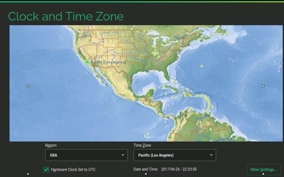
23. Setup the root password.
24. In the Installation Settings screen click Software.
25. Optionally, uncheck GNOME Desktop Environment, if you do not wish to use Graphical Desktop. This optional will reduce the size used for root Partition by 300 MB. Recommend to de-select the “GNOME Desktop Environment” package.
26. Check C/C++ Compiler and Tools Under Development.
27. Check SAP HANA Server Base Under Primary Functions.
28. Check High availability if this VM should be in a cluster (Optional).
29. Click Details, search and install iptop if a network traffic tool is required (Optional).
30. Click Accept.
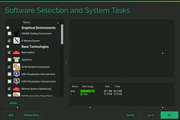
31. Click OK and then click Accept.
32. In the Installation Settings tab disable the firewall.
33. Click Default system target and switch to text mode.
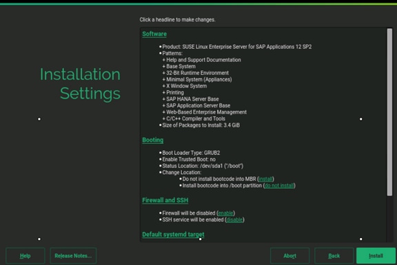
34. Click Install to start the installation.
35. Login as root to the system.
36. Update the OS to latest patch level.
37. Execute the below command to Register the SUSE.
suse_register -i -r -n -a email= <<email_address>> -a regcode-sles=<<registration_code>>
After the registration, the entire repository will be updated.
38. Execute the below command to update the server:
zypper update
39. Follow the on screen instruction to complete the update process.
40. Reboot the server.
Network Time
vi /etc/ntp.conf
server <NTP-SERVER IP>
fudge <NTP-SERVER IP> stratum 10
keys /etc/ntp.keys
trustedkey 1
To configure the OS optimization setting for HANA, complete the following steps:
1. Create a file /etc/init.d/after.local
vi /etc/init.d/after.local
#!/bin/bash
# (c) Cisco Systems Inc. 2014
echo never > /sys/kernel/mm/transparent_hugepage/enabled
. /etc/rc.status
# set sappiness to 30 to aviod swapping
echo "Set swappiness to 30 to avoid swapping"
echo 30 > /proc/sys/vm/swappiness
. /etc/rc.status
2. Add the following lines to /etc/sysctl.conf
#disable IPv6
net.ipv6.conf.all.disable_ipv6 = 1
#
# Controls IP packet forwarding
net.ipv4.ip_forward = 0
# Do not accept source routing
net.ipv4.conf.default.accept_source_route = 0
# Controls the use of TCP syncookies
net.ipv4.tcp_syncookies = 1
fs.inotify.max_user_watches = 65536
kernel.shmmax = 9223372036854775807
kernel.sem = 1250 256000 100 8192
kernel.shmall = 1152921504606846720
kernel.shmmni = 524288
# SAP HANA Database
# Next line modified for SAP HANA Database on 2016.01.04_06.52.38
vm.max_map_count=588100000
fs.file-max = 20000000
fs.aio-max-nr = 196608
vm.memory_failure_early_kill = 1
#
net.core.rmem_max = 16777216
net.core.wmem_max = 16777216
net.core.rmem_default = 16777216
net.core.wmem_default = 16777216
##
net.core.optmem_max = 16777216
net.core.netdev_max_backlog = 300000
net.ipv4.tcp_slow_start_after_idle = 0
net.ipv4.conf.default.promote_secondaries = 1
net.ipv4.conf.all.promote_secondaries = 1
net.ipv4.icmp_echo_ignore_broadcasts = 1
net.ipv4.tcp_rmem = 65536 16777216 16777216
net.ipv4.tcp_wmem = 65536 16777216 16777216
##
net.core.somaxconn=1024
net.ipv4.conf.default.accept_source_route = 0
net.ipv4.tcp_syncookies = 1
##
net.ipv4.tcp_no_metrics_save = 1
net.ipv4.tcp_moderate_rcvbuf = 1
net.ipv4.tcp_window_scaling = 1
net.ipv4.tcp_timestamps = 0
net.ipv4.tcp_sack = 0
net.ipv4.tcp_dsack = 0
net.ipv4.tcp_fsack = 0
net.ipv4.tcp_max_syn_backlog = 16348
net.ipv4.tcp_synack_retries = 3
net.ipv4.tcp_retries2 = 6
net.ipv4.tcp_keepalive_time = 1000
net.ipv4.tcp_tw_recycle = 1
net.ipv4.tcp_tw_reuse = 1
# Linux SAP swappiness recommendation
vm.swappiness=10
# Next line added for SAP HANA Database on 2015.09.16_02.09.34
net.ipv4.ip_local_port_range=40000 65300
#For background information, see SAP Note 2205917 and 1557506
vm.pagecache_limit_mb = 0
vm.pagecache_limit_ignore_dirty = 1
#
sunrpc.tcp_slot_table_entries = 128
sunrpc.tcp_max_slot_table_entries = 128
3. Manually edit "/usr/lib/tuned/sap-hana/tuned.conf" and change/add "force_latency" to the following:
vi /usr/lib/tuned/sap-hana/tuned.conf
force_latency=70
4. Manually create the file "/etc/systemd/logind.conf.d/sap-hana.conf" with the following content:
vi /etc/systemd/logind.conf.d/sap-hana.conf
[Login]
UserTasksMax=infinity
5. Configure the server settings:
zypper install sapconf
tuned-adm profile sap-hana
saptune solution apply HANA
systemctl start tuned
systemctl enable tuned
6. Call saptune with the parameter "HANA" (starting with SLES 12 for SAP Applications SP2):
saptune solution apply HANA
7. Edit /etc/default/grub
8. Search for the line starting with "GRUB_CMDLINE_LINUX_DEFAULT" and append to this line
vi /etc/default/grub
GRUB_CMDLINE_LINUX_DEFAULT “…. intel_idle.max_cstate=1 processor.max_cstate=1 numa_balancing=disable transparent_hugepage=never”
9. Save your changes and run:
grub2-mkconfig -o /boot/grub2/grub.cfg
10. Reboot the server:
RHEL 7.2 Installation on ESXi 6.5
This section describes the OS installation on the ESX data store.
1. OS installer will start Troubleshooting, press Enter.
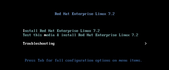
2. Choose Install Red Hat Ent. Linux 7.2 in basic graphics mod. Press Enter.
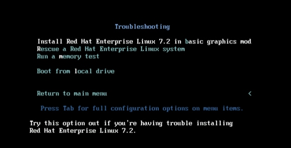
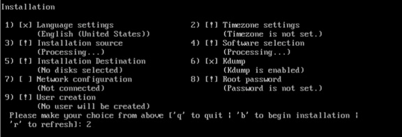
3. Select option 2 to setup the timezone for the system
4. Select the region for the system. In this scenario we selected America (option 2) and press Enter.
5. We selected Los Angeles (Option 82) and press Enter.
6. Option 4 Software selection is already selected right (Minimal Installation).
7. Select option 5 Software destination.
8. Type “c” to continue using the vDisk we created in ESXi.
9. Select option 2 to use the entire disk for the OS and press “c” to continue.
10. Select 1 to create a standard partition (no LVM) and press “c” to continue.
11. Select option 6 to disable the kdump feature.
12. Select 1 to disable kdump and press “c” to continue.
13. Select 8 to setup the root password.
14. Type in the root password and retype the password.
15. Type “b” to start the installation process.
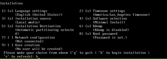
16. Finish the installation and reboot the VM by pressing enter.
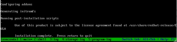
Post Installation Tasks
Configuring the Network
In RHEL 7, systemd and udev support a number of different naming schemes. By default, fixed names are assigned based on firmware, topology, and location information: for example, enp72s0
With this naming convention, although names remain fixed even if hardware is added or removed, names often are more difficult to read than with traditional kernel-native ethX naming: that is, eth0, etc.
Another convention for naming network interfaces, biosdevnames, is available with installation.
If you require to go back the this traditional device names set these parameter later on in the grub2 configuration net.ifnames=0 biosdevname=0
Also, you can disable IPv6 support ipv6.disable=1 when mention this in the grub2 kernel.
1. Log in to the newly installed system as root.
2. Configure the network.
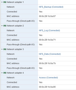
3. Configure the Access network, default GW and the resolv.conf file to be able to reach the RHEL Satellite Server:
nmcli con add con-name Access ifname enp10s0 type ethernet ip4 10.1.1.10/24 gw4 10.1.1.1
cat /etc/sysconfig/network-scripts/ifcfg-Access
TYPE=Ethernet
BOOTPROTO=none
IPADDR=>>IP Address of the Access LAN>>
PREFIX=24
GATEWAY=10.1.1.1
DEFROUTE=yes
IPV4_FAILURE_FATAL=no
IPV6INIT=no
NAME=Access
UUID=d6bcdbc9-ded6-43a6-b854-f5d0ca2370b2
DEVICE=enp14s0
ONBOOT=yes
DNS1=10.17.1.20
DOMAIN=customer.com
4. Restart the Network:
systemctl restart network
Updating the RedHat System
In order to patch the system, the repository must be updated. Note that the installed system doesn’t include any update information. In order to patch the Redhat System, it must be registered and attached to a valid.
Subscription. The following line will register the installation and update the repository information:
subscription-manager register --username <<username>> --password <<password>> --force --auto-attach
yum -y install yum-versionlock
subscription-manager release --set=7.2
1. Apply the security updates. Typically, the kernel is updated as well:
yum --security update
2. Install the base package group:
yum -y groupinstall base
3. Install dependencies in accordance with the SAP HANA Server Installation and Update Guide and the numactl package if the benchmark HWCCT is to be used:
yum install cairo expect graphviz iptraf-ng krb5-workstation krb5-libs libcanberra-gtk2 libicu libpng12 libssh2 libtool-ltdl lm_sensors nfs-utils ntp ntpdate numactl openssl098e openssl PackageKit-gtk3-module rsyslog sudo tcsh xorg-x11-xauth xulrunner screen gtk2 gcc glib glibc-devel glib-devel kernel-devel libstdc++-devel redhat-rpm-config rpm-build zlib-devel
4. Install and enable the tuned profiles for HANA:
yum install tuned-profiles-sap-hana
systemctl start tuned
systemctl enable tuned
tuned-adm profile sap-hana
5. Disable the nomad:
systemctl stop numad
systemctl disable numad
6. Run the full update of all packages:
yum -y update
7. Download and install the libstdc++5 library See: 2338763 - Linux: Running SAP applications compiled with GCC 5.x Download from RedHat: compat-sap-c++-5-5.3.1-10
rpm –Uvh compat-sap-c++-5-5.3.1-10.el7_3.x86_64.rpm
8. Reboot the machine and use the new kernel.
9. Disable SELinux:
vi /etc/sysconfig/selinux
# This file controls the state of SELinux on the system.
# SELINUX= can take one of these three values:
# enforcing - SELinux security policy is enforced.
# permissive - SELinux prints warnings instead of enforcing.
# disabled - No SELinux policy is loaded.
SELINUX=disabled
# SELINUXTYPE= can take one of these two values:
# targeted - Targeted processes are protected,
# mls - Multi Level Security protection.
SELINUXTYPE=targeted
10. Adjust the sunrcp slot table entries:
vi /etc/modprobe.d/sunrpc-local.conf
options sunrpc tcp_max_slot_table_entries=128
![]() The latest RedHat nfs client versions ignore this setting and use the max value of 65536. Therefore ONTAP 9.2 needs to be used for the NetApp AFF A300 storage system.
The latest RedHat nfs client versions ignore this setting and use the max value of 65536. Therefore ONTAP 9.2 needs to be used for the NetApp AFF A300 storage system.
11. Tuned SAP HANA Profile:
tuned-adm profile sap-hana
systemctl enable tuneda
12. Disabling the firewall:
systemctl disable firewalld.service
13. Disabling the LVM2:
systemctl disable lvm2-lvmetad.socket
systemctl disable lvm2-lvmpolld.socket
systemctl disable lvm2-lvmetad.service
systemctl disable lvm2-monitor.service
systemctl disable dm-event.socket
14. Disabling the KVM and iTCO watchdog:
vi /etc/modprobe.d/local-blacklist.conf
blacklist kvm
blacklist iTCO_wdt
blacklist iTCO_vendor_support
15. Sysctl.conf: The following parameters must be set in /etc/sysctl.conf.
#disable IPv6
net.ipv6.conf.all.disable_ipv6 = 1
#
# Controls IP packet forwarding
net.ipv4.ip_forward = 0
# Do not accept source routing
net.ipv4.conf.default.accept_source_route = 0
# Controls the use of TCP syncookies
net.ipv4.tcp_syncookies = 1
fs.inotify.max_user_watches = 65536
kernel.shmmax = 9223372036854775807
kernel.sem = 1250 256000 100 8192
kernel.shmall = 1152921504606846720
kernel.shmmni = 524288
# SAP HANA Database
# Next line modified for SAP HANA Database on 2016.01.04_06.52.38
vm.max_map_count=588100000
fs.file-max = 20000000
fs.aio-max-nr = 196608
vm.memory_failure_early_kill = 1
net.core.rmem_max = 16777216
net.core.wmem_max = 16777216
net.core.rmem_default = 16777216
net.core.wmem_default = 16777216
##
net.core.optmem_max = 16777216
net.core.netdev_max_backlog = 300000
net.ipv4.tcp_slow_start_after_idle = 0
net.ipv4.conf.default.promote_secondaries = 1
net.ipv4.conf.all.promote_secondaries = 1
net.ipv4.icmp_echo_ignore_broadcasts = 1
net.ipv4.tcp_rmem = 65536 16777216 16777216
net.ipv4.tcp_wmem = 65536 16777216 16777216
##
net.core.somaxconn=1024
net.ipv4.conf.default.accept_source_route = 0
net.ipv4.tcp_syncookies = 1
net.ipv4.tcp_no_metrics_save = 1
net.ipv4.tcp_moderate_rcvbuf = 1
net.ipv4.tcp_window_scaling = 1
net.ipv4.tcp_timestamps = 0
net.ipv4.tcp_sack = 0
net.ipv4.tcp_dsack = 0
net.ipv4.tcp_fsack = 0
net.ipv4.tcp_max_syn_backlog = 16348
net.ipv4.tcp_synack_retries = 3
net.ipv4.tcp_retries2 = 6
net.ipv4.tcp_keepalive_time = 1000
net.ipv4.tcp_tw_recycle = 1
net.ipv4.tcp_tw_reuse = 1
# Linux SAP swappiness recommendation
vm.swappiness=10
# Next line added for SAP HANA Database on 2015.09.16_02.09.34
net.ipv4.ip_local_port_range=40000 65300
#For background information, see SAP Note 2205917 and 1557506
vm.pagecache_limit_mb = 0
vm.pagecache_limit_ignore_dirty = 1
#
sunrpc.tcp_slot_table_entries = 128
sunrpc.tcp_max_slot_table_entries = 128
16. Edit the file /etc/ntp.conf to reflect the appropriate ntp servers for the region and start the ntp service:
systemctl enable ntpd
17. Disable Crash Dump:
systemctl disable abrtd
systemctl disable abrt-ccpp
18. Disable core file creation. To disable core dumps for all users, open /etc/security/limits.conf, and add the lines:
* soft core 0
* hard core 0
19. Reboot the OS.
Install Cisco enic Driver
This section describes how to download the Cisco UCS Drivers ISO bundle, which contains most Cisco UCS Virtual Interface Card drivers.
1. In a web browser, navigate to http://www.cisco.com
2. Under Support, click All Downloads.
3. In the product selector, click Products, then click Server - Unified Computing.
4. If prompted, enter your Cisco.com username and password to log in.
![]() You must be signed in to download Cisco Unified Computing System (UCS) drivers.
You must be signed in to download Cisco Unified Computing System (UCS) drivers.
5. Cisco UCS drivers are available for both Cisco UCS B-Series Blade Server Software and Cisco UCS C-Series Rack-Mount UCS-Managed Server Software.
6. Click UCS B-Series Blade Server Software.
7. Click Cisco Unified Computing System (UCS) Drivers.
![]() The latest release version is selected by default. This document is built on Version 3.1(2f)
The latest release version is selected by default. This document is built on Version 3.1(2f)
8. Click 3.1.(2f) Version.
9. Download ISO image of Cisco UCS-related drivers.
10. Choose your download method and follow the prompts to complete your driver download.
11. After the download complete browse the ucs-bxxx-drivers.3.1.2\Linux\Network\Cisco\12x0\RHEL\RHEL7.2 and copy kmod-enic-2.3.0.39-rhel7u2.el7.x86_64.rpm
12. Copy the rpm package to the VM.
13. Update the enic driver:
rpm -Uvh /tmp/kmod-enic-2.3.0.39-rhel7u2.el7.x86_64.rpm
14. grub update to add the HANA specific settings:
grubby –-args=”intel_idle.max_cstate=1 processor.max_cstate=1 numa_balancing=disable transparent_hugepage=never” –-update-kernel /boot/vmlinuz-3.10.0-327.el7.x86_64
Install VMware Tools
1. Click VM in the virtual machine menu, then click Guest > Install/Upgrade VMware Tools and click OK.
2. Create a mount point to mount ISO:
mkdir /mnt/cdrom
3. Mount cdrom:
mount /dev/cdrom /mnt/cdrom
4. Copy the Compiler gzip tar file to a temporary local directory, run:
cp /mnt/cdrom/VMwareTools-<<version>>.tar.gz /tmp/
5. Untar the copied file:
cd /tmp
tar -zxvf VMwareTools-version.tar.gz
6. Change directory to extracted vmware-tools-distrib and run the vmware-install.pl PERL script:
cd /tmp/vmware-tools-distrib
./vmware-install.pl
7. Follow the onscreen instruction to complete the VMware tools installation.
8. Reboot the VM.
vHANA Template
The Virtual Machine created for vHANA can be converted to VM template and this template can be used to deploy multiple vHANA system with customized hardware and storage size.
![]() It is mandatory to connect the ESXi host to vCenter Server to enable VM deployment from templates and edit VM hardware.
It is mandatory to connect the ESXi host to vCenter Server to enable VM deployment from templates and edit VM hardware.
To create a virtual machine (VM) template for vHANA, complete the following steps:
1. Log in to the vCenter using the VMware vSphere Client.
2. In the VMware vSphere client, select the Inventory > VMs and Templates.
3. Right-click the vHANA Virtual Machine.
4. Select Template > Convert to Template.
Deploy vHANA from the Template
To deploy vHANA from the template, complete the following steps:
1. Log in to the vCenter using the VMware vSphere Client.
2. In the VMware vSphere Client, select the Inventory > VMs and Templates.
3. Right-click the vHANA Template. Select Deploy Virtual Machine from this Template.
4. Enter the Name of the vHANA Virtual Machine; Choose the Data Center and VM Directory. Click Next.
5. Choose the Cluster. Click Next.
6. Choose the Datastore. Click Next.
7. Customize using the Customization Wizard
8. Enter the Computer Name and Domain Name. Click Next.
9. Choose the Time Zone. Click Next.
10. Under Network Choose Custom Settings.
11. Click NIC1 and Enter IP Address, Subnet Mask and Default Gateway for vHANA-Access network.
12. For external Storage click on NIC2 and Enter IP Address, Subnet Mask for vHANA-Storage network. Click Next.
13. Enter the DNS server and Domain Name. Click Next.
14. (Optional) Save the Customization.
15. Click Finish.
16. Click Edit virtual hardware. Click Continue.
17. Edit Memory to increase or decrease the Memory Size.
18. Edit the vCPU setting to add or remove number of cores.
![]() Follow the SAP guideline for CPU memory ratio.
Follow the SAP guideline for CPU memory ratio.
19. Click OK.
20. Wait for VM deployment to complete. Power on the Virtual Machine.
Storage for vHANA
The storage configuration and sizing for vHANA is identical to bare metal servers, which has been described in the section Storage for SAP HANA.
The example below details how to create volumes for 256 GB vHANA solution:
1. Open SSH connection to NetApp cluster IP and log in as admin user with the password.
2. vHANA DATA
3. Execute the below commands to create data volume name vhana01_data in the aggregate aggr_hana01 with size 256 GB with export policy vhana-vm
volume create -vserver hana_vs1 -volume vhana01_data -aggregate aggr_hana01 -size 256GB -state online -policy vhana-vm -junction-path /vhana01_data -space-guarantee file -percent-snapshot-space 0 -snapshot-policy none
4. vHANA LOG
5. Execute the below commands to create log volume name vhana01_log in the aggregate aggr_hana02 with size 128 GB with export policy vhana-vm
volume create -vserver hana_vs1 -volume vhana01_log -aggregate aggr_hana02 -size 128GB -state online -policy vhana-vm -junction-path /vhana01_log -space-guarantee file -percent-snapshot-space 0 -snapshot-policy none
6. vHANA Shared
7. Execute the below commands to create shared volume name vhana01_sapexe in the aggregate aggr_hana02 with size 256 GB with export policy vhana-vm
volume create -vserver hana_vs1 -volume vhana01_sapexe -aggregate aggr_hana02 -size 256GB -state online -policy vhana-vm -junction-path /vhana01_sapexe -space-guarantee file -percent-snapshot-space 0 -snapshot-policy none
8. To use NFS for SAP HANA data and log volumes add the following lines to /etc/fstab entry for vHANA
#HANA Shared
vhana-lif01:/vhana01_sapexe /hana/shared nfs rw,bg,vers=3,hard,timeo=600,rsize=65536,wsize=65536,intr,actimeo=0,noatime,nolock 0 0
#HANA DATA
vhana-lif01:/vhana01_data /hana/data nfs rw,bg,vers=3,hard,timeo=600,rsize=65536,wsize=65536,intr,actimeo=500,noatime,nolock 0 0
#HANA LOG
vhana-lif02:/vhana01_log /hana/log nfs rw,bg,vers=3,hard,timeo=600,rsize=65536,wsize=65536,intr,actimeo=500,noatime,nolock 0 0
9. Update the /etc/hosts entry to reflect vhana-lif01 and vhana-lif02 IPs
192.168.51.12 vhana-lif01
192.168.51.13 vhana-lif02
10. Create the required directory to mount /hana/shared /hana/data and /hana/log volumes.
11. Mount all the volumes from /etc/fstab using “mount –a”
vhana-01:~ # df –h
Filesystem Size Used Avail Use% Mounted on
/dev/sda3 57G 3.6G 51G 7% /
udev 127G 144K 127G 1% /dev
tmpfs 127G 648K 127G 1% /dev/shm
/dev/sda1 98M 25M 68M 27% /boot
vhana-lif01:/vhana01_sapexe 256G 128K 256G 1% /hana/shared
vhana-lif01:/vhana01_data 256G 128K 256G 1% /hana/data
vhana-lif02:/vhana01_log 128G 128K 128G 1% /hana/log
12. Make sure that the <SID>adm user owns the data and log volumes – use the chown command after the file systems are mounted.
SAP HANA Installation
Please use the official SAP documentation, which describes the installation process with and without the SAP unified installer.
SAP HANA installation documentation: SAP HANA Server Installation Guide
All other SAP installation and administration documentation is available here: http://service.sap.com/instguides
Important SAP Notes
Read the following SAP Notes before you start the installation. These SAP Notes contain the latest information about the installation, as well as corrections to the installation documentation.
The latest SAP Notes can be found at: https://service.sap.com/notes.
SAP HANA IMDB Related Notes
SAP Note 1514967 - SAP HANA: Central Note
SAP Note 2004651 - SAP HANA Platform SPS 08 Release Note
SAP Note 2075266 - SAP HANA Platform SPS 09 Release Note
SAP Note 1523337 - SAP HANA Database: Central Note
SAP Note 2000003 - FAQ: SAP HANA
SAP Note 1730999![]() - Configuration changes in SAP HANA appliance
- Configuration changes in SAP HANA appliance
SAP Note 1514966![]() - SAP HANA 1.0: Sizing SAP In-Memory Database
- SAP HANA 1.0: Sizing SAP In-Memory Database
SAP Note 1780950![]() - Connection problems due to host name resolution
- Connection problems due to host name resolution
SAP Note 1780950![]() - SAP HANA SPS06: Network setup for external communication
- SAP HANA SPS06: Network setup for external communication
SAP Note 1743225![]() - SAP HANA: Potential failure of connections with scale out nodes
- SAP HANA: Potential failure of connections with scale out nodes
SAP Note 1755396![]() - Released DT solutions for SAP HANA with disk replication
- Released DT solutions for SAP HANA with disk replication
SAP Note 1890444![]() - HANA system slow due to CPU power save mode
- HANA system slow due to CPU power save mode
SAP Note 1681092 - Support for multiple SAP HANA databases on a single SAP HANA appliance
SAP Note 1514966 - SAP HANA: Sizing SAP HANA Database
SAP Note 1637145 - SAP BW on HANA: Sizing SAP HANA Database
SAP Note 1793345 - Sizing for Suite on HANA
Linux Related Notes
SAP Note 1944799 - SAP HANA Guidelines for SLES Operating System
SAP Note 2009879 - SAP HANA Guidelines for RedHat Enterprise Linux (RHEL)
SAP Note 1824819![]() - SAP HANA DB: Recommended OS settings for SLES11/SLES4SAP SP2
- SAP HANA DB: Recommended OS settings for SLES11/SLES4SAP SP2
SAP Note 1731000![]() - Non-recommended configuration changes
- Non-recommended configuration changes
SAP Note 1557506![]() - Linux paging improvements
- Linux paging improvements
SAP Note 1310037![]() - SUSE Linux Enterprise Server 11 - installation notes
- SUSE Linux Enterprise Server 11 - installation notes
SAP Note 1726839![]() - SAP HANA DB: potential crash when using xfs filesystem
- SAP HANA DB: potential crash when using xfs filesystem
SAP Note 1740136![]() - SAP HANA: wrong mount option may lead to corrupt persistency
- SAP HANA: wrong mount option may lead to corrupt persistency
SAP Note 1829651![]() - Time zone settings in SAP HANA scale out landscapes
- Time zone settings in SAP HANA scale out landscapes
SAP Application Related Notes
SAP Note 1658845![]() - SAP HANA DB hardware check
- SAP HANA DB hardware check
SAP Note 1637145![]() - SAP BW on SAP HANA: Sizing SAP In-Memory Database
- SAP BW on SAP HANA: Sizing SAP In-Memory Database
SAP Note 1661202![]() - Support for multiple applications on SAP HANA
- Support for multiple applications on SAP HANA
SAP Note 1681092![]() - Support for multiple SAP HANA databases one HANA aka Multi SID
- Support for multiple SAP HANA databases one HANA aka Multi SID
SAP Note 1577128![]() - Supported clients for SAP HANA 1.0
- Supported clients for SAP HANA 1.0
SAP Note 1808450![]() - Homogenous system landscape for on BW-HANA
- Homogenous system landscape for on BW-HANA
SAP Note 1976729 - Application Component Hierarchy for SAP HANA
SAP Note 1927949 - Standard Behavior for SAP Logon Tickets
SAP Note 1577128 - Supported clients for SAP HANA
Third Party Software
SAP Note 1730928![]() - Using external software in a SAP HANA appliance
- Using external software in a SAP HANA appliance
SAP Note 1730929![]() - Using external tools in an SAP HANA appliance
- Using external tools in an SAP HANA appliance
SAP Note 1730930![]() - Using antivirus software in an SAP HANA appliance
- Using antivirus software in an SAP HANA appliance
SAP Note 1730932![]() - Using backup tools with Backint for SAP HANA
- Using backup tools with Backint for SAP HANA
SAP HANA Virtualization
SAP Note 1788665![]() - SAP HANA running on VMware vSphere VMs
- SAP HANA running on VMware vSphere VMs
SAP Note 2015392 - VMware recommendations for latency-sensitive SAP applications
VMware Wiki from SAP for vHANA
https://wiki.scn.sap.com/wiki/display/VIRTUALIZATION/SAP+Notes+Related+to+VMware
NetApp Configuration Guide for SAP HANA
TR-4290 SAP HANA on NetApp FAS Systems with NFS Configuration Guide
High-Availability (HA) Configuration for Scale-Out
Since HANA revision 35, the ha_provider python class supports the STONITH functionality.
STONITH = Shoot The Other Node In The Head. With this python class, we are able to reboot the failing node to prevent a split brain and thus an inconsistency of the database. Since we use NFSv3, we must implement the STONITH functionality to prevent the database for a corruption because of multiple access to mounted file systems. If a HANA node is failed over to another node, the failed node will be rebooted from the master name server. This eliminates the risk of multiple access to the same file systems.
High-Availability Configuration
The version of ucs_ha_class.py must be at least 1.1
vi ucs_ha_class.py
"""
Function Class to call the reset program to kill the failed host and remove NFS locks for the SAP HANA HA
Class Name ucs_ha_class
Class Phath /usr/sap/<SID>/HDB<ID>/exe/python_support/hdb_ha
Provider Cisco Systems Inc.
Version 1.1 (apiVersion=2 and hdb_ha.client import sudowers)
"""
from hdb_ha.client import StorageConnectorClient
import os
class ucs_ha_class(StorageConnectorClient):
apiVersion = 2
def __init__(self, *args, **kwargs):
super(ucs_ha_class, self).__init__(*args, **kwargs)
def stonith(self, hostname):
os.system ("/bin/logger STONITH HANA Node:" + hostname)
os.system ("/hana/shared/HA/ucs_ipmi_reset.sh " + hostname)
return 0
def about(self):
ver={"provider_company":"Cisco",
"provider_name" :"ucs_ha_class",
"provider_version":"1.0",
"api_version" :2}
self.tracer.debug('about: %s'+str(ver))
print '>> ha about',ver
return ver
@staticmethod
def sudoers():
return ""
def attach(self,storages):
return 0
def detach(self, storages):
return 0
def info(self, paths):
pass
Prepare the script to match the Cisco UCS Manager configured ipmi username and password. Default is ipmi-user sapadm and ipmi-user-password cisco.
vi ucs_ipmi_reset.sh
#!/bin/bash
#set -x
# Cisco Systems Inc.
# SAP HANA High Availability
# Version 1.1 07/2014
# changelog: 09/16: -I lanplus
if [ -z $1 ]
then
echo "please add the hostname to reset to the command line"
exit 1
fi
# Trim the domain name off of the hostname
host=`echo "$1" | awk -F'.' '{print $1}'`
PASSWD=cisco
USER=sapadm
echo $host-ipmi
#
# Shut down the server via ipmitool power off
#
/bin/logger `whoami`" Resetting the HANA Node $host because of an Nameserver reset command"
rc1=`/usr/bin/ipmitool -I lanplus -H $host-ipmi -U $USER -P $PASSWD power status`
if [ "$rc1" = 'Chassis Power is on' ]
then
power="on"
rc2=`/usr/bin/ipmitool -I lanplus -H $host-ipmi -U $USER -P $PASSWD power off`
sleep 5
rc3=`/usr/bin/ipmitool -I lanplus -H $host-ipmi -U $USER -P $PASSWD power status`
echo RC3: $rc3
if [ "$rc3" = 'Chassis Power is on' ]
then
rc2=`/usr/bin/ipmitool -I lanplus -H $host-ipmi -U $USER -P $PASSWD power off`
sleep 10
rc3=`/usr/bin/ipmitool -I lanplus -H $host-ipmi -U $USER -P $PASSWD power status`
if [ "$rc3" = 'Chassis Power is on' ]
then
/bin/logger `whoami`" Resetting the HANA Node $host failed "
exit 1
fi
fi
fi
/bin/logger `whoami`" HANA Node $host switched from ON to OFF "
#
# The locks are released
# We will start the server now to bring it back as standby node
#
rc1=`/usr/bin/ipmitool -I lanplus -H $host-ipmi -U $USER -P $PASSWD power status`
if [ "$rc1" = 'Chassis Power is off' ]
then
power="off"
rc2=`/usr/bin/ipmitool -I lanplus -H $host-ipmi -U $USER -P $PASSWD power on`
echo RC2: $rc2
sleep 8
rc3=`/usr/bin/ipmitool -I lanplus -H $host-ipmi -U $USER -P $PASSWD power status`
echo RC3: $rc3
if [ "$rc3" = 'Chassis Power is off' ]
then
rc2=`/usr/bin/ipmitool -I lanplus -H $host-ipmi -U $USER -P $PASSWD power on`
echo RC2: $rc2
fi
fi
/bin/logger `whoami`" HANA Node $host switched from OFF to ON "
#
# Server is power on and should boot - our work is done
#
/bin/logger `whoami`" Release NFS locks of HANA Node $host done, system is booting"
exit 0
Copy the HA scripts to the shared HA directory under /hana/shared/<SID>/HA
(HANA nameserver is responsible to reset the failed node)
ssh cishana01
mkdir /hana/shared/HA
chown t01adm:sapsys /hana/shared/HA
scp ucs_ipmi_reset.sh /hana/shared/HA/
scp ucs_ha_class.py /hana/shared/HA/
chown t01adm:sapsys /hana/shared/HA/*
Enable the SAP HANA Storage Connector API
The SAP Storage Connector API provides a way to call a user procedure whenever the SAP HANA Nameserver triggers a node failover. The API requires the files mentioned above.
The procedure is executed on the master nameserver.
To activate the procedure in case of a node failover, the global.ini file in
<HANA installdirectory>/<SID>/global/hdb/custom/config/
must be edited and the following entry must be added:
[Storage]
ha_provider = ucs_ha_class
ha_provider_path = /hana/shared/<SID>/HA
cd /hana/shared/<SID>/global/hdb/custom/config
vi global.ini
[persistence]
basepath_datavolumes=/hana/data/ANA
basepath_logvolumes=/hana/log/ANA
[storage]
ha_provider = ucs_ha_class
ha_provider_path = /hana/shared/HA
Modify the /etc/sudoers file and append the following line on all the nodes. By adding the line <sid>adm account can execute commands mentioned without password.
To activate the change, please restart the SAP HANA DB.
Test the IPMI connectivity
Test the ipmi connectivity on ALL nodes:
cishana01:~ # ipmitool -I lanplus -H cishana01-ipmi -U sapadm -P cisco power status
Chassis Power is on
Make sure that all nodes are responding to the ipmitool command and the IP address for the ipmi network match in the /etc/hosts file of all the servers.
Linux Kernel Crash Dump
In the event of server hangs, system panics or a Linux kernel crash, Kdump is used capture kernel's memory for analysis. This section describes how to configure the Server in order to capture kernel crash dump.
Configure the System for Capturing Kernel Core Dumps
1. Make sure you have the following packages installed kdump, kexec-tools, and makedumpfile.
2. Reserve memory for the capture kernel by passing “crashkernel=768M” parameter to the primary kernel in the PXE boot configuration file.
mgmtsrv01:/tftpboot/pxelinux.cfg # vi cishana01
# SAP UCS PXE Boot Definition
display ../boot.msg
default SLES11_SP3
prompt 1
timeout 10
LABEL SLES11_SP3
KERNEL vmlinuz
APPEND initrd=initrd rw rootdev=192.168.127.10:/vol/cishana01 intel_idle.max_cstates=0 processor.max_cstate=0 crashkernel=768M ip=dhcp
3. Activate the kdump system service.
4. Run # chkconfig boot.kdump on
5. Root file system does not have enough space to store a complete memory dump – This will be up to the size of physical memory for a single SAP HANA node. Instead of a local dump destination, an NFS share can be used. Add the network device to be used for the variable: KDUMP_NETCONFIG in /etc/sysconfig/kdump. In order to automatically set up a network device, pass the option "auto". This option will use eth0 and obtain the IP from DHCP server.
## Type: string
## Default: auto
## ServiceRestart: kdump
#
# Network configuration. Use "auto" for auto-detection in initrd, or a string
# that contains the network device and the mode (dhcp,static), separated by
# a colon. Example: "eth0:static" or "eth1:dhcp".
#
# For static configuration, you have to add the configuration to
# KDUMP_COMMANDLINE_APPEND.
#
# See also: kdump(5)
#
KDUMP_NETCONFIG="auto"
6. Pass the dumping method and the destination directory to the parameter: KDUMP_SAVEDIR in /etc/sysconfig/kdump
Supported methods are:
## Type: string
## Default: "file:///var/log/dump"
## ServiceRestart: kdump
#
# Which directory should the dumps be saved in by the default dumper?
# This can be:
#
# - a local file, for example "file:///var/log/dump" (or, deprecated,
# just "/var/log/dump")
# - a FTP server, for example "ftp://user:password@host/var/log/dump"
# - a SSH server, for example "ssh://user:password@host/var/log/dump"
# - a NFS share, for example "nfs://server/export/var/log/dump"
# - a CIFS (SMB) share, for example
# "cifs://user:password@host/share/var/log/dump"
#
# See also: kdump(5) which contains an exact specification for the URL format.
# Consider using the "yast2 kdump" module if you are unsure.
#
KDUMP_SAVEDIR="nfs://192.168.127.14/vol/os_crashdump"
![]() KDUMP_SAVEDIR should have sufficient space to prevent hanging systems waiting for completing the Kdump procedure.
KDUMP_SAVEDIR should have sufficient space to prevent hanging systems waiting for completing the Kdump procedure.
Set Up Magic SysRq (recommended)
For kernel problems other than a kernel oops or panic, a kernel core dump is not triggered automatically. If the system still responds to keyboard input to some degree, a kernel core dump can be triggered manually through a "magic SysRq" keyboard combination (typically: hold down three keys simultaneously: the left Alt key, the Print Screen / SysRq key and a letter key indicating the command - ' s' for sync, ' c' for core dump), if this feature has been enabled.
1. Magic SysRq can be configured in Cisco UCS Manger from KVM console > Macros > User Defined Macros > Manage > New.
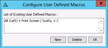
2. To enable the magic SysRq feature permanently, edit /etc/sysconfig/sysctl, change the ENABLE_SYSRQ line to ENABLE_SYSRQ="yes". This change becomes active after a reboot.
# vi /etc/sysconfig/sysctl
## Path: System/Kernel
## Description:
## Type: string
#
# Magic SysRq Keys enable some control over the system even if it
# crashes (e.g. during kernel debugging).
#
# Possible values:
# - no: disable sysrq completely
# - yes: enable all functions of sysrq
# - bitmask of allowed sysrq functions:
# 2 - enable control of console logging level
# 4 - enable control of keyboard (SAK, unraw)
# 8 - enable debugging dumps of processes etc.
# 16 - enable sync command
# 32 - enable remount read-only
# 64 - enable signalling of processes (term, kill, oom-kill)
# 128 - allow reboot/poweroff
# 256 - allow nicing of all RT tasks
#
# For further information see /usr/src/linux/Documentation/sysrq.txt
#
ENABLE_SYSRQ="yes"
3. To enable the feature for the running kernel, run:
# echo 1>/proc/sys/kernel/sysrq
4. Reboot the system for the settings to take effect.
Troubleshooting
1. After reboot to make sure kdump is working correctly, check if boot.kdump service is started.
server01:~ # service boot.kdump status
kdump kernel loaded
running
server01:~ # service boot.kdump restart
Loading kdump
done
2. If the kernel parameter “crashkernel=768M” is not passed correctly, you will see the error as below.
server01:~ # service boot.kdump start
Loading kdump
Regenerating kdump initrd ...
Then try loading kdump kernel
Memory for crashkernel is not reserved
Please reserve memory by passing "crashkernel=X@Y" parameter to the kernel
failed
3. After the boot.kdump service is started, execute “depmod” which handle dependency descriptions for loadable kernel modules. If you are missing any driver it will show the warning, please make sure you have vNIC drivers otherwise, crash kernel will not function properly.
server01:~ # depmod
WARNING: Can't read module /lib/modules/3.0.80-0.7-default/weak-updates/updates/fnic.ko: No such file or directory
4. Execute the command mkinitrd, which creates initial ramdisk images for preloading modules, make sure network and nfs modules are included in the crash kernel. If you are missing nfs module, please check root “/” mount point in /etc/fstab entry.
server01:~ # mkinitrd
Kernel image: /boot/vmlinuz-3.0.80-0.7-default
Initrd image: /boot/initrd-3.0.80-0.7-default
Kernel Modules: hwmon thermal_sys thermal processor fan scsi_mod megaraid_sas scsi_tgt scsi_transport_fc libfc libfcoe fnic af_packet enic sunrpc nfs_acl auth_rpcgss fscache lockd nfs scsi_dh scsi_dh_alua scsi_dh_emc scsi_dh_hp_sw scsi_dh_rdac usb-common usbcore ohci-hcd uhci-hcd ehci-hcd hid usbhid crc-t10dif sd_mod
Features: acpi usb network nfs resume.userspace resume.kernel
42493 blocks
>>> Network: auto
>>> Calling mkinitrd -B -k /boot/vmlinuz-3.0.80-0.7-default -i /tmp/mkdumprd.vqjQzDCHv2 -f 'kdump network' -s ''
Regenerating kdump initrd ...
Kernel image: /boot/vmlinuz-3.0.80-0.7-default
Initrd image: /tmp/mkdumprd.vqjQzDCHv2
Kernel Modules: hwmon thermal_sys thermal processor fan scsi_mod megaraid_sas scsi_tgt scsi_transport_fc libfc libfcoe fnic af_packet enic sunrpc nfs_acl auth_rpcgss fscache lockd nfs scsi_dh scsi_dh_alua scsi_dh_emc scsi_dh_hp_sw scsi_dh_rdac usb-common usbcore ohci-hcd uhci-hcd ehci-hcd hid usbhid nls_utf8 crc-t10dif sd_mod
Features: acpi usb network nfs resume.userspace resume.kernel kdump
55144 blocks
Don't refresh the bootloader. You may have to do that manually!
5. Reboot your system for kdump to configure.
Test Local Kernel Core Dump Capture
To test the local kernel core dump capture, complete the following steps:
If magic SysRq has been configured:
1. Magic-SysRq-S to sync (flush out pending writes).
2. Magic-SysRq-C to trigger the kernel core dump.
3. Alternatively, without magic SysRq:
4. Open a shell or terminal.
5. Run sync.
6. Run echo c >/proc/sysrq-trigger.
The system will boot the crash kernel and start the kernel dump. This can be observed on KVM console of the Cisco UCS manager. Once the system completes the crash dump, verify that a capture file created on 192.168.127.14/vol/os_crashdump/date example 192.168.127.10/vol/os_crashdump/2013-07-13-16:18. As per the parameter set on /etc/sysconfig/kdump (KDUMP_SAVEDIR="nfs://192.168.127.14/vol/os_crashdump”)
As per the http://www.novell.com/support/kb/doc.php?id=3374462, a kernel core dump can be triggered manually through a "magic SysRq" keyboard combination. This can be helpful if the system is hanging instead of going into a kernel panic.
OS Settings for Console Redirection
Add or uncommend the following in /etc/inittab:
se:2345:respawn:/sbin/agetty 115200 ttyS0
Added the following to /etc/security:
ttyS0
Configuration of the file /tftpboot/pxelinux.cfg/<IP in HEX>
Appended the following text to the APPEND line
console=tty1 console=ttyS0,115200
mgmtsrv01:/tftpboot/pxelinux.cfg # cat C0A87F5B
# SAP UCS PXE Boot Definition
display ../boot.msg
default SLES11_SP2
prompt 1
timeout 10
LABEL SLES11_SP2
KERNEL vmlinuz-default
APPEND initrd=initrd_cisco.gz rw rootdev=192.168.127.11:/FS_OS_01/SLES11SP2 rootfsopts=default intel_idle.max_cstate=0 ip=dhcp console=tty1 console=ttyS0,115200 crashkernel=256M-:4G
With this, the Console redirection for SUSE Linux is configured.
Log in to Serial Console
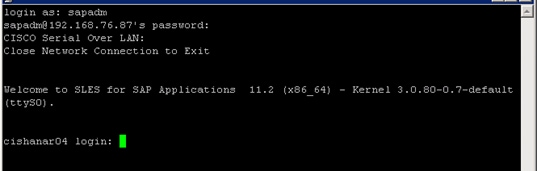
Serial Console POST screen
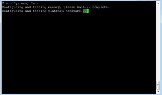
Serial Console Boot Menu
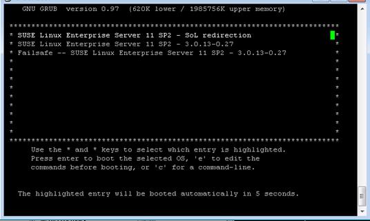
Serial Console OS Booted
Cisco Nexus 9000 Example Configurations of FlexPod for SAP HANA
Cisco Nexus 9000 A
hostname NX9k-A
vdc NX9k-A id 1
allow feature-set fex
allocate interface Ethernet1/1-48
allocate interface Ethernet2/1-12
limit-resource vlan minimum 16 maximum 4094
limit-resource vrf minimum 2 maximum 4096
limit-resource port-channel minimum 0 maximum 768
limit-resource u4route-mem minimum 248 maximum 248
limit-resource u6route-mem minimum 96 maximum 96
limit-resource m4route-mem minimum 58 maximum 58
limit-resource m6route-mem minimum 8 maximum 8
cfs eth distribute
feature udld
feature interface-vlan
feature lacp
feature vpc
feature lldp
username admin password 5 $1$vLVKV/5d$bIjkUqsf3kHjKUyJGxZrw1 role network-admin
no password strength-check
ip domain-lookup
errdisable recovery interval 30
copp profile strict
snmp-server user admin network-admin auth md5 0x3a6326308ce673d7cdbc3cf7f0e4b749 priv 0x3a6326308ce673d7cdbc3cf7f0e4b749 localizedkey
rmon event 1 log trap public description FATAL(1) owner PMON@FATAL
rmon event 2 log trap public description CRITICAL(2) owner PMON@CRITICAL
rmon event 3 log trap public description ERROR(3) owner PMON@ERROR
rmon event 4 log trap public description WARNING(4) owner PMON@WARNING
rmon event 5 log trap public description INFORMATION(5) owner PMON@INFO
ntp server 172.26.163.254 use-vrf management
vlan 1,110,112,127,201,220-225,510,520,1371-1372,3110-3112
vlan 110
name HANA-Storage
vlan 112
name HANA-Admin
vlan 127
name HANA-Boot
vlan 201
name Temp-Storage
vlan 220
name HANA-Internal
vlan 221
name HANA-Backup
vlan 222
name HANA-Client
vlan 223
name HANA-AppServer
vlan 224
name HANA-DataSource
vlan 225
name HANA-Replication
vlan 510
name vHANA-Storage
vlan 520
name vHANA-Access
vlan 1371
name iSCSI-VLAN-A
vlan 1372
name iSCSI-VLAN-B
vlan 3110
name ESX-NFS
vlan 3111
name ESX-MGMT
vlan 3112
name ESX-vMotion
cdp timer 5
spanning-tree port type edge bpduguard default
spanning-tree port type edge bpdufilter default
spanning-tree port type network default
vrf context managementvrf context management
ip route 0.0.0.0/0 172.25.186.1
vpc domain 50
peer-switch
role priority 10
peer-keepalive destination 177.78.78.2 source 177.78.78.1
delay restore 150
peer-gateway
auto-recovery
interface port-channel1
description VPC-Peer
switchport mode trunk
switchport trunk allowed vlan 110,112,127,220-225
switchport trunk allowed vlan add 510,520,1371-1372,3110-3112
spanning-tree port type network
vpc peer-link
interface port-channel11
description VPC to FI-A
switchport mode trunk
switchport trunk allowed vlan 110,112,127,220-225
spanning-tree port type edge trunk
mtu 9216
vpc 11
interface port-channel12
description VPC to FI-B
switchport mode trunk
switchport trunk allowed vlan 110,112,127,220-225
spanning-tree port type edge trunk
mtu 9216
vpc 12
interface port-channel21
description vPC-Backup-FI-A
switchport mode trunk
switchport trunk allowed vlan 221
spanning-tree port type edge trunk
mtu 9216
vpc 21
interface port-channel22
description vPC-Backup-FI-B
switchport mode trunk
switchport trunk allowed vlan 221
spanning-tree port type edge trunk
mtu 9216
vpc 22
interface port-channel31
description VPC to vPC-vHANA-FI-A
switchport mode trunk
switchport trunk allowed vlan 510,520,1371-1372,3110-3112
spanning-tree port type edge trunk
mtu 9216
vpc 31
interface port-channel32
description VPC to vPC-vHANA-FI-B
switchport mode trunk
switchport trunk allowed vlan 510,520,1371-1372,3110-3112
spanning-tree port type edge trunk
mtu 9216
vpc 32
interface port-channel41
description NetApp_CtrlA_OS
switchport mode trunk
switchport trunk allowed vlan 127,1371-1372,3110
spanning-tree port type edge trunk
vpc 41
interface port-channel42
description NetApp_CtrlB_OS
switchport mode trunk
switchport trunk allowed vlan 127,1371-1372,3110
spanning-tree port type edge trunk
vpc 42
interface port-channel44
description NetApp_CtrlA_DATA
switchport mode trunk
switchport trunk allowed vlan 110,510
spanning-tree port type edge trunk
mtu 9216
vpc 44
interface port-channel45
description NetApp_CtrlB_DATA
switchport mode trunk
switchport trunk allowed vlan 110,510
spanning-tree port type edge trunk
mtu 9216
vpc 45
interface port-channel112
description Mgmt-Switch-A
switchport mode trunk
switchport trunk allowed vlan 112,127,3111
spanning-tree port type network
vpc 112
interface port-channel113
description Mgmt-Switch-B
switchport mode trunk
switchport trunk allowed vlan 112,127,3111
spanning-tree port type network
vpc 113
interface Ethernet1/1
description UPLINK-to-Customer-NetWork
interface Ethernet1/2
description UCS-FI-A
switchport mode trunk
switchport trunk allowed vlan 110,112,127,220-225
mtu 9216
channel-group 11 mode active
interface Ethernet1/3
description UPLINK-to-Customer-NetWork
interface Ethernet1/4
description UCS-FI-A
switchport mode trunk
switchport trunk allowed vlan 110,112,127,220-225
mtu 9216
channel-group 11 mode active
interface Ethernet1/6
description UCS-FI-B
switchport mode trunk
switchport trunk allowed vlan 110,112,127,220-225
mtu 9216
channel-group 12 mode active
interface Ethernet1/8
description UCS-FI-B
switchport mode trunk
switchport trunk allowed vlan 110,112,127,220-225
mtu 9216
channel-group 12 mode active
interface Ethernet1/9
description peer-link NX9K-A-1/9--NX9K-B-1/9
switchport mode trunk
switchport trunk allowed vlan 110,112,127,220-225
switchport trunk allowed vlan add 510,520,1371-1372,3110-3112
channel-group 1 mode active
interface Ethernet1/10
description peer-link NX9K-A-1/10--NX9K-B-1/10
switchport mode trunk
switchport trunk allowed vlan 110,112,127,220-225
switchport trunk allowed vlan add 510,520,1371-1372,3110-3112
channel-group 1 mode active
interface Ethernet1/11
description peer-link NX9K-A-1/11--NX9K-B-1/11
switchport mode trunk
switchport trunk allowed vlan 110,112,127,220-225
switchport trunk allowed vlan add 510,520,1371-1372,3110-3112
channel-group 1 mode active
interface Ethernet1/12
description peer-link NX9K-A-1/12--NX9K-B-1/12
switchport mode trunk
switchport trunk allowed vlan 110,112,127,220-225
switchport trunk allowed vlan add 510,520,1371-1372,3110-3112
channel-group 1 mode active
interface Ethernet1/13
interface Ethernet1/14
interface Ethernet1/15
description NetApp_CtrlA_OS
switchport mode trunk
switchport trunk allowed vlan 127,1371-1372,3110
spanning-tree port type edge trunk
channel-group 41 mode active
interface Ethernet1/16
description NetApp_CtrlB_OS
switchport mode trunk
switchport trunk allowed vlan 127,1371-1372,3110
spanning-tree port type edge trunk
channel-group 42 mode active
interface Ethernet1/17
description NetApp_CtrlA_DATA
switchport mode trunk
switchport trunk allowed vlan 110,510
mtu 9216
channel-group 51 mode active
interface Ethernet1/18
description NetApp_CtrlA_DATA
switchport mode trunk
switchport trunk allowed vlan 110,510
mtu 9216
channel-group 51 mode active
interface Ethernet1/19
description NetApp_CtrlB_DATA
switchport mode trunk
switchport trunk allowed vlan 110,510
mtu 9216
channel-group 52 mode active
interface Ethernet1/20
description NetApp_CtrlB_DATA
switchport mode trunk
switchport trunk allowed vlan 110,510
mtu 9216
channel-group 52 mode active
interface Ethernet1/29
description vPC-Backup-6248-A
switchport mode trunk
switchport trunk allowed vlan 221
spanning-tree port type edge trunk
mtu 9216
channel-group 21 mode active
interface Ethernet1/30
description vPC-Backup-6248-B
switchport mode trunk
switchport trunk allowed vlan 221
spanning-tree port type edge trunk
mtu 9216
channel-group 22 mode active
interface Ethernet1/31
description vPC-vHANA-6248-A
switchport mode trunk
switchport trunk allowed vlan 510,520,1371-1372,3110-3112
spanning-tree port type edge trunk
mtu 9216
channel-group 31 mode active
interface Ethernet1/32
description vPC-vHANA-6248-B
switchport mode trunk
switchport trunk allowed vlan 510,520,1371-1372,3110-3112
spanning-tree port type edge trunk
no buffer-boost
mtu 9216
channel-group 32 mode active
interface Ethernet2/11
description Link to Mgmt-Switch-A-P1
switchport mode trunk
switchport trunk allowed vlan 112,127,3111
spanning-tree port type network
channel-group 112 mode active
interface Ethernet2/12
description Link to Mgmt-Switch-B-P1
switchport mode trunk
switchport trunk allowed vlan 112,127,3111
spanning-tree port type network
channel-group 113 mode active
interface mgmt0
vrf member management
ip address 177.78.78.1/24
Cisco Nexus 9000 B
hostname NX9k-B
vdc NX9k-B id 1
allow feature-set fex
allocate interface Ethernet1/1-48
allocate interface Ethernet2/1-12
limit-resource vlan minimum 16 maximum 4094
limit-resource vrf minimum 2 maximum 4096
limit-resource port-channel minimum 0 maximum 768
limit-resource u4route-mem minimum 248 maximum 248
limit-resource u6route-mem minimum 96 maximum 96
limit-resource m4route-mem minimum 58 maximum 58
limit-resource m6route-mem minimum 8 maximum 8
cfs eth distribute
feature udld
feature interface-vlan
feature lacp
feature vpc
feature lldp
username admin password 5 $1$/v26IEcG$eLTpE50QHBgBftxGcO5xG1 role network-admin
no password strength-check
ip domain-lookup
errdisable recovery interval 30
copp profile strict
snmp-server user admin network-admin auth md5 0x217f517b7927f8292f2297a2065a5636 priv 0x217f517b7927f8292f2297a2065a5636 localizedkey
rmon event 1 log trap public description FATAL(1) owner PMON@FATAL
rmon event 2 log trap public description CRITICAL(2) owner PMON@CRITICAL
rmon event 3 log trap public description ERROR(3) owner PMON@ERROR
rmon event 4 log trap public description WARNING(4) owner PMON@WARNING
rmon event 5 log trap public description INFORMATION(5) owner PMON@INFO
ntp server 172.26.163.254 use-vrf management
vlan 1,110,112,127,201,220-225,510,520,1371-1372,3110-3112
vlan 110
name HANA-Storage
vlan 112
name HANA-Admin
vlan 127
name HANA-Boot
vlan 201
name Temp-Storage
vlan 220
name HANA-Internal
vlan 221
name HANA-Backup
vlan 222
name HANA-Client
vlan 223
name HANA-AppServer
vlan 224
name HANA-DataSource
vlan 225
name HANA-Replication
vlan 510
name vHANA-Storage
vlan 520
name vHANA-Access
vlan 1371
name iSCSI-VLAN-A
vlan 1372
name iSCSI-VLAN-B
vlan 3110
name ESX-NFS
vlan 3111
name ESX-MGMT
vlan 3112
name ESX-vMotion
cdp timer 5
spanning-tree port type edge bpduguard default
spanning-tree port type edge bpdufilter default
spanning-tree port type network default
vrf context managementvrf context management
ip route 0.0.0.0/0 172.25.186.1
vpc domain 50
peer-switch
role priority 20
peer-keepalive destination 177.78.78.1 source 177.78.78.2
delay restore 150
peer-gateway
auto-recovery
interface port-channel1
description VPC-Peer
switchport mode trunk
switchport trunk allowed vlan 110,112,127,220-225
switchport trunk allowed vlan add 510,520,1371-1372,3110-3112
spanning-tree port type network
vpc peer-link
interface port-channel11
description VPC to FI-A
switchport mode trunk
switchport trunk allowed vlan 110,112,127,220-225
spanning-tree port type edge trunk
mtu 9216
vpc 11
interface port-channel12
description VPC to FI-B
switchport mode trunk
switchport trunk allowed vlan 110,112,127,220-225
spanning-tree port type edge trunk
mtu 9216
vpc 12
interface port-channel21
description vPC-Backup-FI-A
switchport mode trunk
switchport trunk allowed vlan 221
spanning-tree port type edge trunk
mtu 9216
vpc 21
interface port-channel22
description vPC-Backup-FI-B
switchport mode trunk
switchport trunk allowed vlan 221
spanning-tree port type edge trunk
mtu 9216
vpc 22
interface port-channel31
description VPC to vPC-vHANA-FI-A
switchport mode trunk
switchport trunk allowed vlan 510,520,1371-1372,3110-3112
spanning-tree port type edge trunk
mtu 9216
vpc 31
interface port-channel32
description VPC to vPC-vHANA-FI-B
switchport mode trunk
switchport trunk allowed vlan 510,520,1371-1372,3110-3112
spanning-tree port type edge trunk
mtu 9216
vpc 32
interface port-channel41
description NetApp_CtrlA_OS
switchport mode trunk
switchport trunk allowed vlan 127,1371-1372,3110
spanning-tree port type edge trunk
vpc 41
interface port-channel42
description NetApp_CtrlB_OS
switchport mode trunk
switchport trunk allowed vlan 127,1371-1372,3110
spanning-tree port type edge trunk
vpc 42
interface port-channel44
description NetApp_CtrlA_DATA
switchport mode trunk
switchport trunk allowed vlan 110,510
spanning-tree port type edge trunk
mtu 9216
vpc 44
interface port-channel45
description NetApp_CtrlB_DATA
switchport mode trunk
switchport trunk allowed vlan 110,510
spanning-tree port type edge trunk
mtu 9216
vpc 45
interface port-channel112
description Mgmt-Switch-A
switchport mode trunk
switchport trunk allowed vlan 112,127,3111
spanning-tree port type network
vpc 112
interface port-channel113
description Mgmt-Switch-B
switchport mode trunk
switchport trunk allowed vlan 112,127,3111
spanning-tree port type network
vpc 113
interface Ethernet1/1
description UPLINK-to-Customer-NetWork
interface Ethernet1/2
description UCS-FI-A
switchport mode trunk
switchport trunk allowed vlan 110,112,127,220-225
mtu 9216
channel-group 11 mode active
interface Ethernet1/3
description UPLINK-to-Customer-NetWork
interface Ethernet1/4
description UCS-FI-A
switchport mode trunk
switchport trunk allowed vlan 110,112,127,220-225
mtu 9216
channel-group 11 mode active
interface Ethernet1/6
description UCS-FI-B
switchport mode trunk
switchport trunk allowed vlan 110,112,127,220-225
mtu 9216
channel-group 12 mode active
interface Ethernet1/8
description UCS-FI-B
switchport mode trunk
switchport trunk allowed vlan 110,112,127,220-225
mtu 9216
channel-group 12 mode active
interface Ethernet1/9
description peer-link NX9K-A-1/9--NX9K-B-1/9
switchport mode trunk
switchport trunk allowed vlan 110,112,127,220-225
switchport trunk allowed vlan add 510,520,1371-1372,3110-3112
channel-group 1 mode active
interface Ethernet1/10
description peer-link NX9K-A-1/10--NX9K-B-1/10
switchport mode trunk
switchport trunk allowed vlan 110,112,127,220-225
switchport trunk allowed vlan add 510,520,1371-1372,3110-3112
channel-group 1 mode active
interface Ethernet1/11
description peer-link NX9K-A-1/11--NX9K-B-1/11
switchport mode trunk
switchport trunk allowed vlan 110,112,127,220-225
switchport trunk allowed vlan add 510,520,1371-1372,3110-3112
channel-group 1 mode active
interface Ethernet1/12
description peer-link NX9K-A-1/12--NX9K-B-1/12
switchport mode trunk
switchport trunk allowed vlan 110,112,127,220-225
switchport trunk allowed vlan add 510,520,1371-1372,3110-3112
channel-group 1 mode active
interface Ethernet1/13
interface Ethernet1/14
interface Ethernet1/15
description NetApp_CtrlA_OS
switchport mode trunk
switchport trunk allowed vlan 127,1371-1372,3110
spanning-tree port type edge trunk
channel-group 41 mode active
interface Ethernet1/16
description NetApp_CtrlB_OS
switchport mode trunk
switchport trunk allowed vlan 127,1371-1372,3110
spanning-tree port type edge trunk
channel-group 42 mode active
interface Ethernet1/17
description NetApp_CtrlA_DATA
switchport mode trunk
switchport trunk allowed vlan 110,510
mtu 9216
channel-group 51 mode active
interface Ethernet1/18
description NetApp_CtrlA_DATA
switchport mode trunk
switchport trunk allowed vlan 110,510
mtu 9216
channel-group 51 mode active
interface Ethernet1/19
description NetApp_CtrlB_DATA
switchport mode trunk
switchport trunk allowed vlan 110,510
mtu 9216
channel-group 52 mode active
interface Ethernet1/20
description NetApp_CtrlB_DATA
switchport mode trunk
switchport trunk allowed vlan 110,510
mtu 9216
channel-group 52 mode active
interface Ethernet1/29
description vPC-Backup-6248-A
switchport mode trunk
switchport trunk allowed vlan 221
spanning-tree port type edge trunk
mtu 9216
channel-group 21 mode active
interface Ethernet1/30
description vPC-Backup-6248-B
switchport mode trunk
switchport trunk allowed vlan 221
spanning-tree port type edge trunk
mtu 9216
channel-group 22 mode active
interface Ethernet1/31
description vPC-vHANA-6248-A
switchport mode trunk
switchport trunk allowed vlan 510,520,1371-1372,3110-3112
spanning-tree port type edge trunk
mtu 9216
channel-group 31 mode active
interface Ethernet1/32
description vPC-vHANA-6248-B
switchport mode trunk
switchport trunk allowed vlan 510,520,1371-1372,3110-3112
spanning-tree port type edge trunk
no buffer-boost
mtu 9216
channel-group 32 mode active
interface Ethernet2/11
description Link to Mgmt-Switch-A-P1
switchport mode trunk
switchport trunk allowed vlan 112,127,3111
spanning-tree port type network
channel-group 112 mode active
interface Ethernet2/12
description Link to Mgmt-Switch-B-P1
switchport mode trunk
switchport trunk allowed vlan 112,127,3111
spanning-tree port type network
channel-group 113 mode active
interface mgmt0
vrf member management
ip address 177.78.78.2/24
Shailendra Mruthunjaya, Technical Marketing Engineer, Cisco Systems, Inc.
Shailendra is a Technical Marketing Engineer with Cisco UCS Solutions and Performance Group and has over 4 years of experience on SAP HANA with Cisco UCS platform. Shailendra has designed several SAP landscapes in public and private cloud environment. He focused currently on developing and validating infrastructure best practices for SAP applications on Cisco UCS Servers, Cisco Nexus products and Storage technologies.
Ralf Klahr, Technical Marketing Engineer, Cisco Systems, Inc.
Ralf is a Technical Marketing Engineer with Cisco UCS Solutions and Performance Group and has over 20 years of experience in the IT industry focusing on SAP technologies. He specializes in SAP Landscape virtualization, Solution High Availability and SAP NetWeaver Basis technology. He is currently focusing on the SAP HANA infrastructure design and validation on Cisco UCS Servers, Cisco Nexus products and various Storage technologies to ensure reliable customer deployments.
Marco Schoen, Technical Marketing Engineer, NetApp
Marco is a Technical Marketing Engineer with NetApp and has over 15 years of experience in the IT industry focusing on SAP technologies. His specialization areas include SAP NetWeaver Basis technology and SAP HANA. He is currently focusing on the SAP HANA infrastructure design, validation and certification on NetApp Storage solutions and products including various server technologies.
Acknowledgements
For their support and contribution to the design, validation, and creation of this Cisco Validated Design, we would like to thank:
· Siva Sivakumar, Cisco Systems, Inc.
· Erik Lillestolen, Cisco Systems, Inc.
· Chris O'Brien, Cisco Systems, Inc.
· Nils Bauer, NetApp
· Bernd Herth NetApp
 Feedback