Cisco UCS Integrated Infrastructure for Big Data and Analytics with MapR Converged Data Platform Using MapR Streams
Available Languages

Cisco UCS Integrated Infrastructure for Big Data and Analytics with MapR Converged Data Platform Using MapR Streams
Building a 64 Node Hadoop Cluster
 Last Updated: August 26, 2016
Cisco Validated Design
The CVD program consists of systems and solutions designed, tested, and documented to facilitate faster, more reliable, and more predictable customer deployments. For more information visit
http://www.cisco.com/go/designzone.
ALL DESIGNS, SPECIFICATIONS, STATEMENTS, INFORMATION, AND RECOMMENDATIONS (COLLECTIVELY, "DESIGNS") IN THIS MANUAL ARE PRESENTED "AS IS," WITH ALL FAULTS. CISCO AND ITS SUPPLIERS DISCLAIM ALL WARRANTIES, INCLUDING, WITHOUT LIMITATION, THE WARRANTY OF MERCHANTABILITY, FITNESS FOR A PARTICULAR PURPOSE AND NONINFRINGEMENT OR ARISING FROM A COURSE OF DEALING, USAGE, OR TRADE PRACTICE. IN NO EVENT SHALL CISCO OR ITS SUPPLIERS BE LIABLE FOR ANY INDIRECT, SPECIAL, CONSEQUENTIAL, OR INCIDENTAL DAMAGES, INCLUDING, WITHOUT LIMITATION, LOST PROFITS OR LOSS OR DAMAGE TO DATA ARISING OUT OF THE USE OR INABILITY TO USE THE DESIGNS, EVEN IF CISCO OR ITS SUPPLIERS HAVE BEEN ADVISED OF THE POSSIBILITY OF SUCH DAMAGES.
THE DESIGNS ARE SUBJECT TO CHANGE WITHOUT NOTICE. USERS ARE SOLELY RESPONSIBLE FOR THEIR APPLICATION OF THE DESIGNS. THE DESIGNS DO NOT CONSTITUTE THE TECHNICAL OR OTHER PROFESSIONAL ADVICE OF CISCO, ITS SUPPLIERS OR PARTNERS. USERS SHOULD CONSULT THEIR OWN TECHNICAL ADVISORS BEFORE IMPLEMENTING THE DESIGNS. RESULTS MAY VARY DEPENDING ON FACTORS NOT TESTED BY CISCO.
CCDE, CCENT, Cisco Eos, Cisco Lumin, Cisco Nexus, Cisco StadiumVision, Cisco TelePresence, Cisco WebEx, the Cisco logo, DCE, and Welcome to the Human Network are trademarks; Changing the Way We Work, Live, Play, and Learn and Cisco Store are service marks; and Access Registrar, Aironet, AsyncOS, Bringing the Meeting To You, Catalyst, CCDA, CCDP, CCIE, CCIP, CCNA, CCNP, CCSP, CCVP, Cisco, the Cisco Certified Internetwork Expert logo, Cisco IOS, Cisco Press, Cisco Systems, Cisco Systems Capital, the Cisco Systems logo, Cisco Unity, Collaboration Without Limitation, EtherFast, EtherSwitch, Event Center, Fast Step, Follow Me Browsing, FormShare, GigaDrive, HomeLink, Internet Quotient, IOS, iPhone, iQuick Study, IronPort, the IronPort logo, LightStream, Linksys, MediaTone, MeetingPlace, MeetingPlace Chime Sound, MGX, Networkers, Networking Academy, Network Registrar, PCNow, PIX, PowerPanels, ProConnect, ScriptShare, SenderBase, SMARTnet, Spectrum Expert, StackWise, The Fastest Way to Increase Your Internet Quotient, TransPath, WebEx, and the WebEx logo are registered trademarks of Cisco Systems, Inc. and/or its affiliates in the United States and certain other countries.
All other trademarks mentioned in this document or website are the property of their respective owners. The use of the word partner does not imply a partnership relationship between Cisco and any other company. (0809R)
© 2016 Cisco Systems, Inc. All rights reserved.
Table of Contents
Lambda Architecture - Combining Real-time and Batch Processing
Cisco UCS Integrated Infrastructure for Big Data with MapR and MapR Streams
Cisco UCS 6200 Series Fabric Interconnects
Cisco UCS 6300 Series Fabric Interconnects
Cisco UCS C-Series Rack Mount Servers
Cisco UCS Virtual Interface Cards (VICs)
MapR Converged Data Platform 5.1
MapR Enterprise-Grade Platform Services
Port Configuration on Fabric Interconnects
Server Configuration and Cabling for Cisco UCS C-Series M4
Software Distributions and Versions
Red Hat Enterprise Linux (RHEL)
Performing Initial Setup of Cisco UCS 6296 Fabric Interconnects
Configure Fabric Interconnect A
Configure Fabric Interconnect B
Logging Into Cisco UCS Manager
Upgrading UCSM Software to Version 3.1(1g)
Adding a Block of IP Addresses for KVM Access
Creating Pools for Service Profile Templates
Creating Policies for Service Profile Templates
Creating Host Firmware Package Policy
Creating the Local Disk Configuration Policy
Creating a Service Profile Template
Configuring the Storage Provisioning for the Template
Configuring Network Settings for the Template
Configuring the vMedia Policy for the Template
Configuring Server Boot Order for the Template
Configuring Server Assignment for the Template
Configuring Operational Policies for the Template
Installing Red Hat Enterprise Linux 7.2
Setting Up Password-less Login
Creating a Red Hat Enterprise Linux (RHEL) 7.2 Local Repo
Creating the Red Hat Repository Database.
Set Up all Nodes to use the RHEL Repository
Upgrading the Cisco Network Driver for VIC1227
Disable Transparent Huge Pages
Cluster Verification and Micro-Benchmark
Running the Cluster Verification Script
Change Permissions to Executable
Preparing Packages and Repositories
RPM Repositories for MapR Core Software
RPM Repositories for Hadoop Ecosystem Tools
Formatting Disks with the disksetup Script
Identify and Format the Data Disks for MapR
Installing the Cluster License
Using Web-based MCS to Install the License
Installing a License from the Command Line (optional)
Restarting MapR Services after License Installation
Installing Additional Hadoop Components
Apache Hadoop is a framework that allows distributed processing of large data sets with custom applications for both big data and analytics and is one of the fastest-growing technologies providing a competitive advantage for businesses across industries. Previously, the primary method for tapping into the value of big data was through batch processing of the dataset.
Recent improvements in technology now allow the ability for fast interactive analysis and real-time processing of streaming data. The challenge now is to design and build a reliable big data system that simultaneously handles batch processing, interactive analysis and real-time processing of streaming data. This has led to the development of the Lambda Architecture. Lambda Architecture is a framework for designing big data applications with a generic architecture with built-in capabilities for fault tolerance against hardware failures, software bugs, etc., and it supports use cases that address both low latency queries, and scaling and sizing of the system with manageable extensibility to accommodate new features.
The MapR Converged Data Platform integrates the power of Hadoop and Spark with global event streaming, real-time database capabilities and enterprise storage for developing and running innovative data applications built around the Lambda Architecture. This platform is powered by one of the industry’s fastest, most reliable, secure and open data infrastructures, including MapR Streams: a global publish-subscribe event-streaming system for big data.
MapR Streams is the first big data-scale streaming system built into a converged data platform. It makes data available instantly to stream-processing and other applications, and is the only big data streaming system to support global event replication reliably at IoT scale.
The MapR Converged Data Platform allows enterprises to build reliable, real-time applications by providing: a single cluster for streams, file storage database and analytics, persistence of streaming data, providing direct access to batch and interactive frameworks, a unified security framework for data-in-motion and data-at-rest with authentication, authorization and encryption, and a utility-grade reliability with self-healing and no single point-of-failure architecture.
The Cisco UCS® Integrated Infrastructure for Big Data and Analytics with MapR Converged Data Platform enables the next-generation of big data architecture by providing simplified and centralized management, industry-leading performance, and a linearly scaling infrastructure and software platform. The configuration detailed in the document can be scaled to clusters of various sizes depending on the application demand. Up to 80 servers (5 racks) can be supported with no additional switching in a single Cisco UCS domain. Scaling beyond 5 racks (80 servers) can be implemented by interconnecting multiple Cisco UCS domains using Nexus 9000 Series switches or Cisco Application Centric Infrastructure (ACI), scalable to thousands of servers and to hundreds of petabytes of storage, and managed from a single pane using Cisco UCS Central.
Introduction
Big data technology has evolved from exclusively processing with batch jobs against large data sets to processing with fast interactive analysis and processing of real-time streaming data. Today’s enterprises need the tools to develop robust, reliable applications as defined by the Lambda Architecture, and the ability to economically administer and support these systems.
The MapR Converged Data Platform integrates the power of Hadoop and Spark with global event streaming, real-time database capabilities and enterprise storage for developing and running innovative data applications. MapR was engineered for the data center with IT operations in mind. MapR enables big data applications using Hadoop, Spark and more to serve business-critical needs that cannot afford to lose data, must run on a 24x7 basis and require immediate recovery from node and site failures. The Cisco UCS Integrated Infrastructure for Big Data and Analytics and MapR Converged Data Platform support these capabilities for the broadest set of applications from batch analytics to interactive querying and real-time streaming.
Solution
This CVD describes a scalable architecture and deployment procedures for the MapR Converged Data Platform on the Cisco UCS Integrated Infrastructure for Big Data and Analytics.
As one of the technology leaders in Hadoop, the MapR Converged Data Platform distribution provides enterprise-class big data solutions that are fast to develop and easy to administer. With significant investment in critical technologies, MapR offers a complete Hadoop platform - a platform that is fully optimized for performance and scalability.
Deployed as part of a comprehensive data center architecture, the Cisco UCS Integrated Infrastructure for Big Data and Analytics with MapR fundamentally transforms the way that organizations do business with Hadoop technology by delivering a powerful and flexible infrastructure that: increases business and IT agility, reduces total cost of ownership (TCO), and delivers exceptional return on investment (ROI) at scale.
The solution is built on the Cisco UCS Integrated Infrastructure for Big Data and Analytics and includes computing, storage, network and unified management capabilities to help companies manage the vast amount of data they collect today.
The Cisco Unified Computing System infrastructure uses Cisco UCS 6200/6300 Series Fabric Interconnects and Cisco UCS C-Series Rack Servers. This architecture is specifically designed for performance and linear scalability for big data workloads.
Audience
This document describes the architecture and deployment procedures for the MapR Converged Data Platform on a 64 Cisco UCS C240 M4 node cluster based on Cisco UCS Integrated Infrastructure for Big Data and Analytics. The intended audience of this document includes, but is not limited to, sales engineers, field consultants, professional services, IT managers, partner engineering and customers who want to deploy the MapR Converged Data Platform on Cisco UCS Integrated Infrastructure for Big Data and Analytics.
Solution Summary
This CVD describes in detail the process of installing the MapR Converged Data Platform 5.1 and the configuration details of the cluster. It also details application configuration for MapR, and the installation of additional services, like Spark, MapR Steams, etc.
The current version of Cisco UCS Integrated Infrastructure for Big Data and Analytics offers the following configurations depending on the compute and storage requirements as shown in Table 1.
Table 1 Cisco UCS Integrated Infrastructure for Big Data and Analytics Configuration Details
| Performance Optimized Option 1 (UCS-SL-CPA4-P1) |
Performance Optimized Option 2 (UCS-SL-CPA4-P2) |
Performance Optimized Option 3 (UCS-SL-CPA4-P3) |
Capacity Optimized Option 1 UCS-SL-CPA4-C1 |
Capacity Optimized Option 2 UCS-SL-CPA4-C2 |
| 2 Cisco UCS 6296 UP, 96-port Fabric Interconnect. |
2 Cisco UCS 6296 UP, 96-port Fabric Interconnect. |
2 Cisco UCS 6332 Fabric Interconnect. |
2 Cisco UCS 6296 UP, 96-port Fabric Interconnect. |
2 Cisco UCS 6296 UP, 96-port Fabric Interconnect. |
| 16 Cisco UCS C240 M4 Rack Servers (SFF), each with: |
16 Cisco UCS C240 M4 Rack Servers (SFF), each with: |
16 Cisco UCS C240 M4 Rack Servers (SFF), each with: |
16 Cisco UCS C240 M4 Rack Servers (LFF), each with: |
16 Cisco UCS C240 M4 Rack Servers (LFF), each with: |
| 2 Intel Xeon processors E5-2680 v4 CPUs (14 cores on each CPU) |
2 Intel Xeon processors E5-2680 v4 CPUs (14 cores on each CPU) |
2 Intel Xeon processors E5-2680 v4 CPUs (14 cores on each CPU) |
2 Intel Xeon processors E5-2620 v4 CPUs (8 cores each CPU) |
2 Intel Xeon processors E5-2620 v4 CPUs (8 cores each CPU) |
| 256 GB of memory |
256 GB of memory |
256 GB of memory |
128 GB of memory |
256 GB of memory |
| Cisco 12-Gbps SAS Modular Raid Controller with 2-GB flash-based write cache (FBWC) |
Cisco 12-Gbps SAS Modular Raid Controller with 2-GB flash-based write cache (FBWC) |
Cisco 12-Gbps SAS Modular Raid Controller with 2-GB flash-based write cache (FBWC) |
Cisco 12-Gbps SAS Modular Raid Controller with 2-GB flash-based write cache (FBWC) |
Cisco 12-Gbps SAS Modular Raid Controller with 2-GB flash-based write cache (FBWC) |
| 24 1.2-TB 10K SFF SAS drives (460 TB total) |
24 1.8-TB 10K SFF SAS drives (691 TB total) |
24 1.8-TB 10K SFF SAS drives (691 TB total) |
12 6-TB 7.2K LFF SAS drives (1152 TB total) |
12 8-TB 7.2K LFF SAS drives (1536 TB total) |
| 2 240-GB 6-Gbps 2.5-inch Enterprise Value SATA SSDs for Boot |
2 240-GB 6-Gbps 2.5-inch Enterprise Value SATA SSDs for Boot |
2 240-GB 6-Gbps 2.5-inch Enterprise Value SATA SSDs for Boot |
2 240-GB 6-Gbps 2.5-inch Enterprise Value SATA SSDs for Boot |
2 240-GB 6-Gbps 2.5-inch Enterprise Value SATA SSDs for Boot |
| Cisco UCS VIC 1227 (with 2 10 GE SFP+ ports) |
Cisco UCS VIC 1227 (with 2 10 GE SFP+ ports) |
Cisco UCS VIC 1387 (with 2 40 GE QSFP ports) |
Cisco UCS VIC 1227 (with 2 10 GE SFP+ ports) |
Cisco UCS VIC 1227 (with 2 10 GE SFP+ ports) |
MapR Converged Data Platform
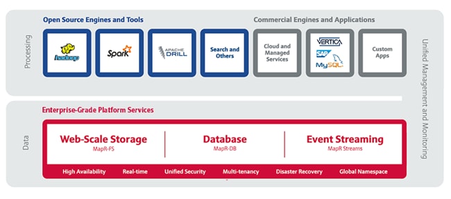
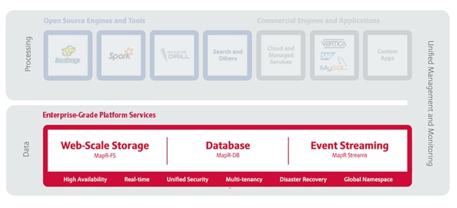
The MapR Converged Data Platform (Figure 1) integrates Hadoop and Spark with real-time database capabilities, global event streaming and scalable enterprise storage to power a new generation of big data applications. The MapR Platform delivers enterprise grade security, reliability and real-time performance while dramatically lowering both hardware and operational costs of your most important applications and data.
Figure 1 The MapR Converged Data Platform
MapR supports dozens of open source projects and is committed to using industry-standard APIs to provide a frictionless method of developing and deploying new applications that can meet the most stringent production runtime requirements.
Enterprise-Grade Platform Services
MapR Platform Services are the core data handling capabilities of the MapR Converged Data Platform. Modules include MapR-FS, MapR-DB and MapR Streams. Its enterprise-friendly design provides a familiar set of file and data management services, including a global namespace, high availability, data protection, self-healing clusters, access control, real-time performance, secure multi-tenancy, and management and monitoring.
Open Source Engines and Tools
MapR packages a broad set of Apache open source ecosystem projects that enable big data applications. The goal is to provide an open platform that provides the right tool for the job. MapR tests and integrates open source ecosystem projects such as Spark, Hive, Drill, HBase and Mesos, among others.
Commercial Engines & Applications
One of the key developer benefits of the MapR Converged Data Platform is its basis on well known, open APIs and interfaces. This enables commercial software vendors such as SAP Hana and SAS to easily deploy large-scale applications onto the MapR Platform. It also means that even small teams of developers can create enterprise-grade software products by exploiting the built-in protections of the MapR Platform in combination with mature commercial processing engines.
Lambda Architecture - Combining Real-time and Batch Processing
Big data architectures are commonly separated into two mutually exclusive models: traditional batch processing using MapReduce and real-time processing using a technology like Storm or Spark Streaming. Often, business requirements drive the adoption of one of these architectures and the popular way to combine these models has been to use the Lambda Architecture.
This approach combines real-time and batch layers providing the best of both worlds. It also has many additional benefits. The Lambda Architecture serves a wide range of workloads and use cases, including batch processing, interactive analysis and low-latency real-time processing, and also creates a robust system that is fault-tolerant against hardware failures, software issues and human error, as well as being linearly scalable.
Figure 2 The Lambda Architecture
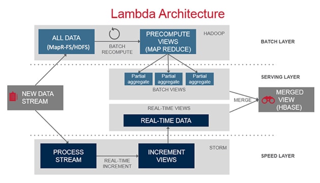
The Lambda Architecture as shown in Figure 2 has three major components. First, the Batch Layer manages the dataset, which is immutable and append-only. Being immutable makes it easy to recover from software issues and human error; append-only simplifies the database design and performance tuning. This layer also pre-computes views of the data, called batch views, used to satisfy query requirements.
Second, the Serving Layer indexes the batch views so that they can be queried with low-latency, i.e., interactively and in an ad-hoc fashion.
Third, the Speed Layer handles all needs that require low-latency. It uses fast, incremental algorithms that deal with recent data only. All real-time stream data processing happens in the speed layer.
Each of these layers can be implemented using various big data technologies. The batch layer datasets are stored in the distributed filesystem (MapR-FS) and use MapReduce (or Spark) to create batch views. The serving layer uses NoSQL technologies like HBase. Lastly, the speed layer can be implemented using real-time processing technologies like Storm or Spark Streaming.
The MapR Converged Data Platform provides all the technologies to implement this architecture while also providing additional benefits. With MapR’s innovations the high-speed streaming data can be written directly to the Hadoop storage while allowing the real-time processing applications to run as independent services within the cluster. This creates a very resilient architecture. The real-time processing applications become subscribers to the incoming data feeds. If the application goes down due to some failure, there is no data loss. A new instance of the application picks up the data stream where the original left off.
MapR Reference Architecture
Figure 3 shows the base configuration of 64 nodes with SFF (1.8TB) drives.
Figure 3 Reference Architecture for MapR
![]() Note: If a customer decides to use the Cisco UCS 6300 Series Fabric Interconnect (40 Gbps) for the configuration instead of the Cisco UCS 6200 Series Fabric Interconnect in Performance Optimized Option 3, the only change will be to add in the Cisco VIC 1387, and the rest of the configuration will be exactly the same.
Note: If a customer decides to use the Cisco UCS 6300 Series Fabric Interconnect (40 Gbps) for the configuration instead of the Cisco UCS 6200 Series Fabric Interconnect in Performance Optimized Option 3, the only change will be to add in the Cisco VIC 1387, and the rest of the configuration will be exactly the same.
Table 2 Configuration Details
| Component |
Description |
| Connectivity |
2 Cisco UCS 6296UP 96-Port Fabric Interconnects Up to 80 servers with no additional switching infrastructure |
| MapR Nodes |
64 Cisco UCS C240 M4 Rack Servers Resource Manager and Data Nodes. Spark Executors are collocated on a Data Node. *Please refer to the Service Assignment section for specific service assignment and configuration details. |
Cisco UCS Integrated Infrastructure for Big Data with MapR and MapR Streams
The Cisco UCS Integrated Infrastructure for Big Data and Analytics solution for MapR is based on Cisco UCS Integrated Infrastructure for Big Data and Analytics, a highly scalable architecture designed to meet a variety of scale-out application demands with seamless data integration and management integration capabilities built using the following components:
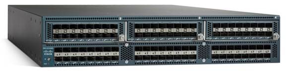
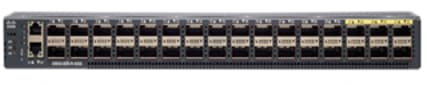
Cisco UCS 6200 Series Fabric Interconnects
Cisco UCS 6200 Series Fabric Interconnects (Figure 4) provide high-bandwidth, low-latency connectivity for servers, with integrated, unified management provided for all connected devices by Cisco UCS Manager. Deployed in redundant pairs, Cisco Fabric Interconnects offer the full active-active redundancy, performance, and exceptional scalability needed to support the large number of nodes that are typical in clusters serving big data applications.
Cisco UCS Manager enables rapid and consistent server configuration using service profiles, automating ongoing system maintenance activities such as firmware updates across the entire cluster as a single operation. Cisco UCS Manager also offers advanced monitoring with options to raise alarms and send notifications about the health of the entire cluster.
Figure 4 Cisco UCS 6296UP 96-Port Fabric Interconnect
Cisco UCS 6300 Series Fabric Interconnects
Cisco UCS 6300 Series Fabric Interconnects (Figure 5) is the newest series of Fabric Interconnects from Cisco. The Cisco UCS 6300 series Fabric interconnects are a core part of Cisco UCS, Providing low-latency, lossless 10 and 40 Gigabit Ethernet, Fiber Channel over Ethernet (FCoE), and Fiber Channel functions with management capabilities for system. All servers attached to Fabric interconnects become part of a single, highly available management domain.
Figure 5 Cisco UCS 6332 UP 32 -Port Fabric Interconnect
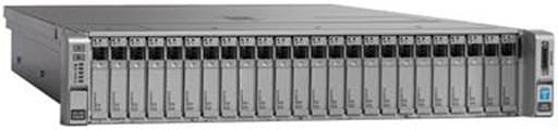
Cisco UCS C-Series Rack Mount Servers
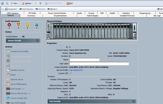
Cisco UCS C-Series Rack Mount C220 M4 High-Density Rack Servers (Small Form Factor Disk Drive Model), and Cisco UCS C240 M4 High-Density Rack Servers (Small Form Factor Disk Drive Model) (Figure 6), are enterprise-class systems that support a wide range of computing, I/O, and storage-capacity demands in compact designs.
Cisco UCS C-Series Rack-Mount Servers are based on the Intel Xeon E5-2600 v4 series processors family that delivers the best combination of performance, flexibility and efficiency gains with 12-Gbps SAS throughput. The Cisco UCS C240 M4 servers provides 24 DIMM (PCIe) 3.0 slots and can support up to 1.5 TB of main memory (128 or 256 GB is typical for big data applications).
It can support a range of disk drive and SSD options; Specifically, Cisco UCS C240 M4 supports twenty-four Small Form Factor (SFF) disk drives plus two (optional) internal SATA boot drives for a total of 26 internal drives in the Performance-optimized option or twelve Large Form Factor (LFF) disk drives option plus two (optional) internal SATA boot drives for a total of 14 internal drives are supported in the Capacity-optimized option.
Cisco UCS Virtual Interface Cards 1227 (VICs), are designed for the M4 generation of Cisco UCS C-Series Rack Servers (both C240 and C220 servers), are optimized for high-bandwidth and low-latency cluster connectivity, with support for up to 256 virtual devices that are configured on demand through Cisco UCS Manager.
Figure 6 Cisco UCS C240 M4 Rack Server
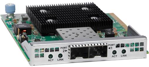
Cisco UCS Virtual Interface Cards (VICs)
Cisco UCS Virtual Interface Cards (VICs) (Figure 7) are unique to Cisco. Cisco UCS Virtual Interface Cards incorporate next-generation converged network adapter (CNA) technology from Cisco, and offer dual 10-Gbps ports designed for use with Cisco UCS C-Series Rack-Mount Servers.
Optimized for virtualized networking, these cards deliver high performance and bandwidth utilization, and support up to 256 virtual devices. The Cisco UCS Virtual Interface Card (VIC) 1227 is a dual-port, Enhanced Small Form-Factor Pluggable (SFP+), 10 Gigabit Ethernet, and Fiber Channel over Ethernet (FCoE)-capable, PCI Express (PCIe) modular LAN on motherboard (mLOM) adapter.
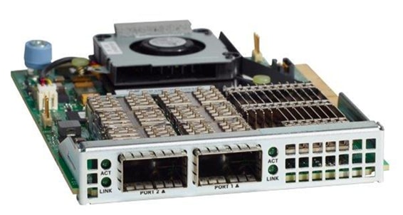
The Cisco UCS Virtual Interface Card 1387 (Figure 8) offers dual-port Enhanced Quad Small Form-Factor Pluggable (QSFP) 40 Gigabit Ethernet and Fiber Channel over Ethernet (FCoE) in a modular-LAN-on-motherboard (mLOM) form factor. The mLOM slot can be used to install a Cisco VIC without consuming a PCIe slot providing greater I/O expandability.
Cisco UCS Manager
Cisco UCS Manager (Figure 9) resides within the Cisco UCS 6200 Series Fabric Interconnect. It makes the system self-aware and self-integrating, managing all of the system components as a single logical entity. Cisco UCS Manager can be accessed through an intuitive graphical user interface (GUI), a command-line interface (CLI), or an XML application-programming interface (API). Cisco UCS Manager uses service profiles to define the personality, configuration, and connectivity of all resources within Cisco UCS, radically simplifies provisioning of resources so that the process takes minutes instead of days. This simplification allows IT departments to shift their focus from constant maintenance to strategic business initiatives.
MapR Converged Data Platform 5.1
As one of the technology leaders in Hadoop, the MapR Converged Data Platform provides enterprise-class big data solutions that are fast to develop and easy to administer. With significant investment in critical technologies, MapR offers one of the industry’s most comprehensive Hadoop platforms, fully optimized for performance and scalability. MapR’s distribution delivers more than a dozen tested and validated Hadoop software modules over a fortified data platform, offering exceptional ease of use, reliability and performance for big data solutions.
Features of MapR Converged Data Platform are:
· Performance – Ultra-fast performance and throughput
· Scalability – Up to a trillion files, with no restrictions on the number of nodes in a cluster
· Standards-based API’s and tools – Standard Hadoop API’s, ODBC, JDBC, LDAP, Linux PAM, and more
· MapR Direct Access NFS – Random read/write, real-time data flows, existing non-Java applications work seamlessly
· Manageability – Advanced management console, rolling upgrades, REST API support
· Integrated security – Kerberos and non-Kerberos options with wire-level encryption
· Advanced multi-tenancy – Volumes, data placement control, job placement control, queues, and more
· Consistent snapshots – Full data protection with point-in-time recovery
· High availability – Ubiquitous HA with a no-NameNode architecture, YARN HA, NFS HA
· Disaster recovery – Cross-site replication with mirroring
· MapR-DB – Integrated enterprise-grade NoSQL database
· MapR Streams – Global publish-subscribe event streaming system for big data
MapR Enterprise-Grade Platform Services
MapR Platform Services (Figure 10) are the core data handling capabilities of the MapR Converged Data Platform. Modules include MapR-FS, MapR-DB and MapR Streams. Its enterprise-friendly design provides a familiar set of file and data management services, including a global namespace, high availability, data protection, self-healing clusters, access control, real-time performance, secure multi-tenancy, and management and monitoring.
Figure 10 MapR Enterprise-grade Platform Services
Enterprise Storage
MapR-FS is an enterprise standard POSIX file system that provides high-performance read/write data storage for the MapR Converged Data Platform. MapR-FS includes important features for production deployments such as fast NFS access, access controls, and transparent data compression at a virtually unlimited scale.
Database
MapR-DB is an enterprise-grade, high performance, in-Hadoop NoSQL database management system. It is used to add real-time, operational analytics capabilities to applications built on the Hadoop or Spark ecosystems. Because it is integrated into the MapR Converged Data Platform, it inherits the protections and high performance capabilities.
Event Streaming
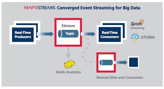
MapR Streams is a global publish-subscribe event streaming system for big data. It connects data producers and consumers worldwide in real-time, with unlimited scale. MapR Streams is the first big data-scale streaming system built into a converged data platform. It makes data available instantly to stream processing and other applications, and is the only big data streaming system to support global event replication reliably at IoT scale.
MapR Streams: Event Streaming on a Global Scale
Many big data sources are continuous flows of data in real time: sensor data, log files, transaction data to name just a few. Enterprises are struggling to deal with the high volume and high velocity of the data using existing bulk data-oriented tools.
MapR Streams (Figure 11) manages streaming data for real-time processing with enterprise-grade security and reliability at a global scale. It connects data producers and consumers worldwide in real time, with unlimited scale. MapR Streams scales to billions of events per second, millions of topics, and millions of producer and consumer applications. Geographically dispersed MapR clusters can be joined into a global fabric, passing event messages between producer and consumer applications in any topology, including one-to-one and many-to-many.
This centralized architecture provides real-time access to streaming data for batch or interactive processing on a global scale with enterprise features including secure access-control, encryption, cross data center replication, multi-tenancy and utility-grade uptime.
Figure 11 MapR Streams: Event Streaming for Big Data
MapR Streams makes data available instantly to stream processing and other applications, providing:
· Kafka API for real-time producers and consumers for easy application migration.
· Out-of-the-box integration with popular stream processing frameworks like Spark Streaming, Storm and Flink.
MapR Streams globally replicates event data at IoT-scale with:
· Arbitrary topology supporting thousands of clusters across the globe. Topologies of connected clusters include one-to-one, one-to-many, many-to-one, many-to-many, star, ring and mesh. Topology loops are automatically handled to avoid data duplication.
· Global metadata replication. Stream metadata is replicated alongside data, allowing producers and consumers to failover between sites for high availability. Data is spread across geographically distributed locations via cross-cluster replication to ensure business continuity should an entire site-wide disaster occur.
MapR Open Source Technologies
MapR packages a broad set of Apache open source ecosystem projects that enable big data applications. The goal is to provide an open platform that provides the right tool for the job. MapR tests and integrates open source ecosystem projects such as Spark, Drill, Solr, HBase, among others. MapR is the only Hadoop vendor that supports multiple versions of key Apache projects providing more flexibility in updating the environment.
Figure 12 MapR Open Source Engines and Tools
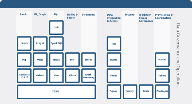
Figure 12 above shows the Apache open source projects supported by the MapR Converged Data Platform. Features of some of the key technologies are highlighted below. In conjunction with the data ingestion capabilities provided by MapR Streams these technologies are building blocks for a system based on the Lambda Architecture.
MapReduce
MapReduce is a powerful framework for processing large, distributed sets of structured or unstructured data on a Hadoop cluster. The key feature of MapReduce is its ability to perform processing across an entire cluster of nodes, with each node processing its local data. This feature makes MapReduce orders of magnitude faster than legacy methods of processing big data. MapReduce is a common choice to perform the pre-compute processing of batch views in the batch layer of the Lambda Architecture.
HBase
HBase is a database that runs on a Hadoop cluster. It is not a traditional relational database management system (RDBMS). Data stored in HBase also does not need to fit into a rigid schema as with an RDBMS, making it ideal for storing unstructured or semi-structured data. HBase stores data in a table-like format with the ability to store billions of rows with millions of columns over multiple nodes in a cluster. HBase can be used to store the pre-computed batch views of data held in the serving layer of the Lambda Architecture.
Drill
Drill is an open source, low-latency query engine for big data that delivers secure and interactive SQL analytics at petabyte scale. It can discover schemas on-the-fly and enable immediate exploration of data stored in Hadoop and NoSQL stores across a variety of data formats and sources.
Drill is fully ANSI SQL compliant, integrates seamlessly with existing BI and visualization tools, and supports thousands of users across thousands of nodes accessing data in the terabyte and petabyte range. Drill can operate on the merged view of data from the serving layer and speed layer of the Lambda Architecture providing a complete historical and real-time picture.
Spark
Spark is a fast and general-purpose engine for large-scale data processing. By adding Spark to the Hadoop deployment and analysis platform, and running it all on Cisco UCS Integrated Infrastructure for Big Data and Analytics, customers can accelerate streaming, interactive queries, machine learning and batch workloads, and offering experiences that deliver more insights in less time.
Spark unifies a broad range of capabilities: batch processing, real-time stream processing, advanced analytic capabilities, machine learning and interactive exploration that can intelligently optimize applications. Spark’s key advantage is speed: most operations are performed in memory eliminating disk I/O as a constraint; calculations are performed and results are delivered only when needed; and results can be configured to persist in memory making multiple reads of the same dataset orders of magnitude faster than traditional MapReduce programs.
In the Lambda Architecture, Spark can replace the MapReduce calculation of pre-computed batch views in the batch layer. It can also be used for fast, interactive analysis on the merged view of data from the serving and speed layers. Finally, Spark Streaming operates on data in real-time in the speed layer.
Spark Streaming
Spark Streaming is an extension of the core Spark API that enables high-throughput, fault-tolerant stream processing of live data streams. Data can be ingested from many sources like MapR Streams, Kafka, Flume, Twitter or TCP sockets and processed using complex algorithms expressed with high-level distributed data processing functions like map, reduce and join.
Processed data can be pushed out to file systems, databases and live dashboards. Spark Streaming is built on top of Spark, so users can apply Spark's built-in machine learning algorithms (MLlib) and graph processing algorithms (GraphX) on data streams.
Spark Streaming brings Spark's language-integrated API to stream processing, letting users write streaming applications the same way as batch jobs (in Java, Python and Scala). It is also highly fault-tolerant, able to detect and recover from data loss mid-stream due to node or process failure
The MapR Converged Data Platform enables the development of streaming and NoSQL applications on a single cluster. By using Spark Streaming, MapR Streams, and MapR-DB together, real-time operational applications can be developed that allow for data ingestion at high speeds.
Requirements
This CVD describes architecture and deployment procedures for MapR 5.1 on a 64 Cisco UCS C240 M4SX node cluster based on Cisco UCS Integrated Infrastructure for Big Data and Analytics. The solution goes into detail configuring MapR 5.1 on the Cisco UCS Integrated infrastructure for Big Data. In addition it also details the configuration for MapR Streams for various use cases.
The Performance cluster configuration consists of the following:
· Two Cisco UCS 6296UP Fabric Interconnects
· 64 Cisco UCS C240 M4 Rack-Mount servers (16 per rack)
· Four Cisco R42610 standard racks
· Eight Vertical Power distribution units (PDUs), (Country Specific)
Rack and PDU Configuration
Each rack consists of two vertical PDUs. The master rack consists of two Cisco UCS 6296UP Fabric Interconnects, sixteen Cisco UCS C240 M4 Servers connected to each of the vertical PDUs for redundancy; thereby, ensuring availability during power source failure. The expansion rack consists of sixteen Cisco UCS C240 M4 Servers connected to each of the vertical PDUs for redundancy; maintaining availability during power source failure.
![]() Note: Please contact your Cisco representative for country specific information.
Note: Please contact your Cisco representative for country specific information.
Table 3 describes the rack configurations of rack 1 (master rack) and racks 2-4 (expansion racks).
Table 3 Rack 1 (Master Rack) Racks 2-4 (Expansion Racks)
| Cisco |
Master Rack |
Cisco |
Expansion Rack |
| 42URack |
|
42URack |
|
| 42 |
Cisco UCS FI 6296UP |
42 |
Unused |
| 41 |
41 |
Unused |
|
| 40 |
Cisco UCS FI 6296UP |
40 |
Unused |
| 39 |
39 |
Unused |
|
| 38 |
Unused |
38 |
Unused |
| 37 |
37 |
||
| 36 |
Unused |
36 |
Unused |
| 35 |
35 |
Unused |
|
| 34 |
Unused |
34 |
Unused |
| 33 |
33 |
Unused |
|
| 32 |
Cisco UCS C240 M4 |
32 |
Cisco UCS C240 M4 |
| 31 |
31 |
||
| 30 |
Cisco UCS C240 M4 |
30 |
Cisco UCS C240 M4 |
| 29 |
29 |
||
| 8 |
Cisco UCS C240 M4 |
28 |
Cisco UCS C240 M4 |
| 27 |
27 |
||
| 26 |
Cisco UCS C240 M4 |
26 |
Cisco UCS C240 M4 |
| 25 |
25 |
||
| 24 |
Cisco UCS C240 M4 |
24 |
Cisco UCS C240 M4 |
| 23 |
23 |
||
| 22 |
Cisco UCS C240 M4 |
22 |
Cisco UCS C240 M4 |
| 21 |
21 |
||
| 20 |
Cisco UCS C240 M4 |
20 |
Cisco UCS C240 M4 |
| 19 |
19 |
||
| 18 |
Cisco UCS C240 M4 |
18 |
Cisco UCS C240 M4 |
| 17 |
17 |
||
| 16 |
Cisco UCS C240 M4 |
16 |
Cisco UCS C240 M4 |
| 15 |
15 |
||
| 14 |
Cisco UCS C240 M4 |
14 |
Cisco UCS C240 M4 |
| 13 |
13 |
||
| 12 |
Cisco UCS C240 M4 |
12 |
Cisco UCS C240 M4 |
| 11 |
11 |
||
| 10 |
Cisco UCS C240 M4 |
10 |
Cisco UCS C240 M4 |
| 9 |
9 |
||
| 8 |
Cisco UCS C240 M4 |
8 |
Cisco UCS C240 M4 |
| 7 |
7 |
||
| 6 |
Cisco UCS C240 M4 |
6 |
Cisco UCS C240 M4 |
| 5 |
5 |
||
| 4 |
Cisco UCS C240 M4 |
4 |
Cisco UCS C240 M4 |
| 3 |
3 |
||
| 2 |
Cisco UCS C240 M4 |
2 |
Cisco UCS C240 M4 |
| 1 |
1 |
Port Configuration on Fabric Interconnects
| Port Type |
Port Number |
| Network |
1 |
| Server |
2 to 65 |
Server Configuration and Cabling for Cisco UCS C-Series M4
The Cisco UCS C-Series M4 rack server is equipped with Intel Xeon E5-2680 v4 processors; 256 GB of memory, Cisco UCS Virtual Interface Card 1227, Cisco 12-Gbps SAS Modular Raid Controller with 2-GB FBWC, Cisco UCS C240 M4 servers here are equipped with 24 1.8-TB 10K SFF SAS drives, 2 240-GB SATA SSD for Boot.
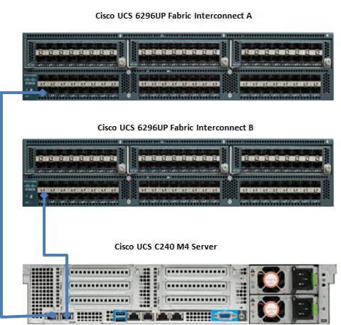
Figure 13 illustrates the port connectivity between the Cisco UCS 6296UP Fabric Interconnects, and a Cisco UCS C240 M4 server. Sixteen Cisco UCS C240 M4 servers are used in master rack configurations.
Figure 13 Fabric Topology for Cisco C240 M4
For more information on physical connectivity and single-wire management see:
For more information on physical connectivity illustrations and cluster setup, see:
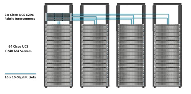
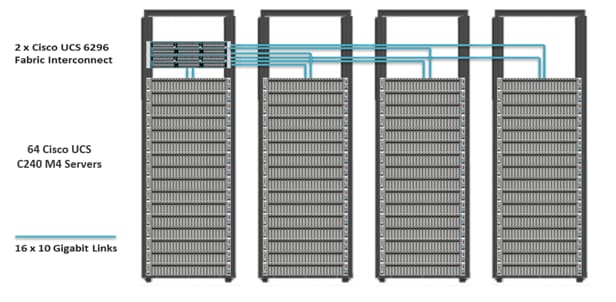
Figure 14 depicts a 64-node cluster. Every rack has 16 Cisco UCS C240 M4 servers. Each link in the figure represents a 16 x 10 Gigabit Ethernet link from each of the 16 servers connecting to a Cisco Fabric Interconnect as a direct connect. Every server is connected to both Fabric Interconnects represented with a dual link.
Figure 14 64 Nodes Cluster Configuration
Software Distributions and Versions
The software distributions required versions are listed below.
MapR
MapR Hadoop is API-compatible and includes or works with the family of Hadoop ecosystem components such as Spark, Hive, Pig, Flume, and others. For more information visit https://www.mapr.com/
Red Hat Enterprise Linux (RHEL)
The operating system supported is Red Hat Enterprise Linux 7.2. For more information visit http://www.redhat.com.
Software Versions
The software versions tested and validated in this document are shown in Table 4.
| Layer |
Component |
Version or Release |
| Compute |
Cisco UCS C240-M4 |
C240M4.2.0.10c |
| Network |
Cisco UCS 6296UP |
UCS 3.1(1g) A |
| Cisco UCS VIC1227 Firmware |
4.1.1(d) |
|
| Cisco UCS VIC1227 Driver |
2.3.0.20 |
|
| Storage |
LSI SAS 3108 |
24.9.1-0011 |
|
|
LSI MegaRAID SAS Driver |
06.810.10.00 |
| Software |
Red Hat Enterprise Linux Server |
7.2 (x86_64) |
| Cisco UCS Manager |
3.1(1g) |
|
| MapR |
5.1 |
![]() Note: The latest drivers can be downloaded from the link below:
Note: The latest drivers can be downloaded from the link below:
https://software.cisco.com/download/release.html?mdfid=283862063&flowid=25886&softwareid=283853158&release=1.5.7d&relind=AVAILABLE&rellifecycle=&reltype=latest
![]() Note:The Latest Supported RAID controller Driver is already included with the RHEL 7.2 operating system
Note:The Latest Supported RAID controller Driver is already included with the RHEL 7.2 operating system
![]() Note:Cisco UCS C240 M4 Rack Servers with Broadwell (E5 -2680 v4) CPUs are supported from Cisco UCS Firmware 3.1(1g) onwards.
Note:Cisco UCS C240 M4 Rack Servers with Broadwell (E5 -2680 v4) CPUs are supported from Cisco UCS Firmware 3.1(1g) onwards.
Fabric Configuration
This section provides details for configuring a fully redundant, highly available Cisco UCS 6296 fabric configuration.
· Initial setup of the Fabric Interconnect A and B.
· Connect to Cisco UCS Manager using the virtual IP address if using the web browser.
· Launch Cisco UCS Manager.
· Enable server, uplink and appliance ports.
· Start discovery process.
· Create pools and polices for service profile template.
· Create the Service Profile template and 64 Service profiles.
· Associate Service Profiles to servers.
Performing Initial Setup of Cisco UCS 6296 Fabric Interconnects
This section describes the initial setup of the Cisco UCS 6296 Fabric Interconnects A and B.
Configure Fabric Interconnect A
1. Connect to the console port on the first Cisco UCS 6296 Fabric Interconnect.
2. At the prompt to enter the configuration method, enter console to continue.
3. If asked to either perform a new setup or restore from backup, enter setup to continue.
4. Enter y to continue to set up a new Fabric Interconnect.
5. Enter y to enforce strong passwords.
6. Enter the password for the admin user.
7. Enter the same password again to confirm the password for the admin user.
8. When asked if this fabric interconnect is part of a cluster, answer y to continue.
9. Enter A for the switch fabric.
10. Enter the cluster name for the system name.
11. Enter the Mgmt0 IPv4 address.
12. Enter the Mgmt0 IPv4 netmask.
13. Enter the IPv4 address of the default gateway.
14. Enter the cluster IPv4 address.
15. To configure DNS, answer y.
16. Enter the DNS IPv4 address.
17. Answer y to set up the default domain name.
18. Enter the default domain name.
19. Review the settings that were printed to the console, and if they are correct, answer yes to save the configuration.
20. Wait for the login prompt to make sure the configuration has been saved.
Configure Fabric Interconnect B
1. Connect to the console port on the second Cisco UCS 6296 Fabric Interconnect.
2. When prompted to enter the configuration method, enter console to continue.
3. The installer detects the presence of the partner Fabric Interconnect and adds this fabric interconnect to the cluster. Enter y to continue the installation.
4. Enter the admin password that was configured for the first Fabric Interconnect.
5. Enter the Mgmt0 IPv4 address.
6. Answer yes to save the configuration.
7. Wait for the login prompt to confirm that the configuration has been saved.
For more information on configuring Cisco UCS 6200 Series Fabric Interconnect, see: http://www.cisco.com/en/US/docs/unified_computing/ucs/sw/gui/config/guide/2.0/b_UCSM_GUI_Configuration_Guide_2_0_chapter_0100.html.
Logging Into Cisco UCS Manager
To login to Cisco UCS Manager, complete the following steps:
1. Open a Web browser and navigate to the Cisco UCS 6296 Fabric Interconnect cluster address.
2. Click the Launch link to download the Cisco UCS Manager software.
3. If prompted to accept security certificates, accept as necessary.
4. When prompted, enter admin for the username and enter the administrative password.
5. Click Login to log in to the Cisco UCS Manager.
Upgrading UCSM Software to Version 3.1(1g)
This document assumes the use of UCS 3.1(1g) Refer to Cisco UCS 3.1 Release (upgrade the Cisco UCS Manager software and Cisco UCS 6296 Fabric Interconnect software to version 3.1(1g). Also, make sure the Cisco UCS C-Series version 3.1(1g) software bundle is installed on the Fabric Interconnects.
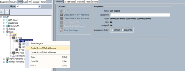
Adding a Block of IP Addresses for KVM Access
To create a block of KVM IP addresses for server access in the Cisco UCS environment, compete the following steps.
1. Select the LAN tab at the top of the left window (Figure 15).
2. Select Pools > IpPools > Ip Pool ext-mgmt.
3. Right-click IP Pool ext-mgmt.
4. Select Create Block of IPv4 Addresses.
Figure 15 Adding a Block of IPv4 Addresses for KVM Access Part 1
5. Enter the starting IP address of the block and number of IPs needed, as well as the subnet and gateway information as shown in Figure 16.
Figure 16 Adding Block of IPv4 Addresses for KVM Access Part 2
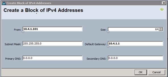
6. Click OK to create the IP block.
7. Click OK in the Message box.
Enabling Uplink Ports
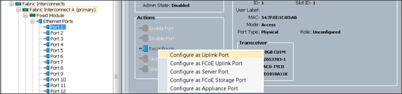
To enable uplinks ports, complete the following steps:
1. Select the Equipment tab on the top left of the window.
2. Select Equipment > Fabric Interconnects > Fabric Interconnect A (primary) > Fixed Module.
3. Expand the Unconfigured Ethernet Ports section.
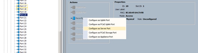
4. Select Port 1 that is connected to the uplink switch, right-click, then select Reconfigure > Configure as Uplink Port. (Figure 17)
5. Select Show Interface and select 10GB for Uplink Connection.
6. A pop-up window appears to confirm your selection. Click Yes then OK to continue.
7. Select Equipment > Fabric Interconnects > Fabric Interconnect B (subordinate) > Fixed Module.
8. Expand the Unconfigured Ethernet Ports section.
9. Select Port number 1, which is connected to the uplink switch, right-click, then select Reconfigure > Configure as Uplink Port.
10. Select Show Interface and select 10GB for Uplink Connection.
11. A pop-up window appears to confirm your selection. Click Yes then OK to continue.
Figure 17 Enabling Uplink Ports
Configuring VLANs
VLANs are configured as in shown in Table 5.
| VLAN |
NIC Port |
Function |
| VLAN36 |
eth0 |
Mgmt/Data1 |
| VLAN37 |
eth1 |
Data2 |
All of the VLANs created need to be trunked to the upstream distribution switch connecting to the fabric interconnects. For this deployment VLAN36 is configured for management access (installing and configuring OS, Clustershell commands, set up NTP, user connectivity etc.) and both VLAN36 and VLAN37 are used for Hadoop Data traffic.
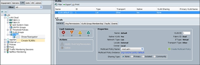
To configure VLANs in the Cisco UCS Manager GUI, complete the following steps:
1. Select the LAN tab in the left pane in the Cisco UCSM GUI.
2. Select LAN > LAN Cloud > VLANs.
3. Right-click the VLANs under the root organization.
4. Select Create VLANs to create the VLAN (Figure 18).
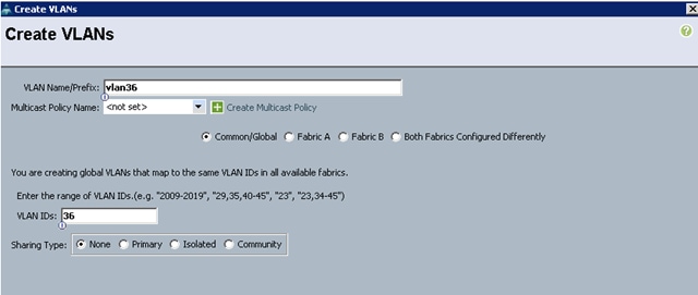
5. Enter vlan36 for the VLAN Name.
6. Keep multicast policy as <not set>.
7. Select Common/Global for vlan36.
8. Enter 36 in the VLAN IDs field for the Create VLAN IDs ().
9. Click OK and then, click Finish.
10. Click OK in the success message box.
Figure 19 Creating VLAN for Data
11. Click OK and then, click Finish.
12. Select the LAN tab in the left pane in the Cisco UCSM GUI.
13. Select LAN > LAN Cloud > VLANs.
14. Right-click the VLANs under the root organization.
15. Select Create VLANs to create the VLAN.
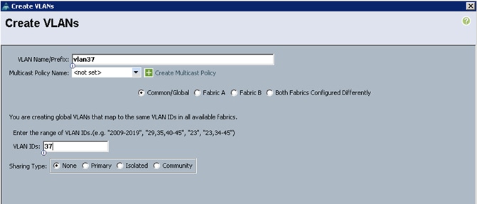
16. Enter vlan37 for the VLAN Name.
17. Keep multicast policy as <not set>.
18. Select Common/Global for vlan37.
19. Enter 37 in the VLAN IDs field for the Create VLAN IDs.
20. Click OK and then, click Finish.
21. Click OK in the success message box.
Figure 18 Creating VLAN for Data
22. Click OK and then, click Finish.
Enabling Server Ports
To enable server ports, complete the following steps:
1. Select the Equipment tab on the top left of the window.
2. Select Equipment > Fabric Interconnects > Fabric Interconnect A (primary) > Fixed Module.
3. Expand the Unconfigured Ethernet Ports section.
4. Select all the ports that are connected to the Servers right-click them, and select Reconfigure > Configure as a Server Port.
5. A pop-up window appears to confirm the selection. Click Yes then OK to continue.
6. Select Equipment > Fabric Interconnects > Fabric Interconnect B (subordinate) > Fixed Module.
7. Expand the Unconfigured Ethernet Ports section.
8. Select all the ports that are connected to the Servers right-click them, and select Reconfigure > Configure as a Server Port.
9. A pop-up window appears to confirm the selection. Click Yes, then OK to continue.
Figure 19 Enabling Ethernet Ports Server Ports
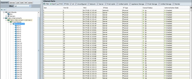
After the Server Discovery, Port 1 will be a Network Port and Ports 2-65 will be Server Ports.
Figure 20 Ethernet Ports List
Creating Pools for Service Profile Templates
Creating an Organization
Organizations are used as a means to arrange and restrict access to various groups within the IT organization, thereby enabling multi-tenancy of the compute resources. This document does not assume the use of Organizations; however the necessary steps are provided for future reference.
To configure an organization within the Cisco UCS Manager GUI, complete the following steps:
1. Click New on the top left corner in the right pane in the Cisco UCS Manager GUI.
2. Select Create Organization from the options
3. Enter a name for the organization.
4. (Optional) Enter a description for the organization.
5. Click OK.
6. Click OK in the success message box.
Creating MAC Address Pools
To create MAC address pools, complete the following steps:
1. Select the LAN tab on the left of the window.
2. Select Pools > root.
3. Right-click MAC Pools under the root organization.
4. Select Create MAC Pool to create the MAC address pool (Figure 21).
5. Enter ucs for the name of the MAC pool.
6. (Optional) Enter a description of the MAC pool.
7. Select Assignment Order Sequential.
8. Click Next.
9. Click Add.
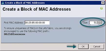
10. Specify a starting MAC address (Figure 22).
11. Specify a size of the MAC address pool, which is sufficient to support the available server. resources.
12. Click OK.
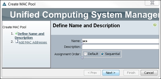
Figure 22 Specifying first MAC Address and Size
13. Click Finish.
Figure 23 Add MAC Addresses
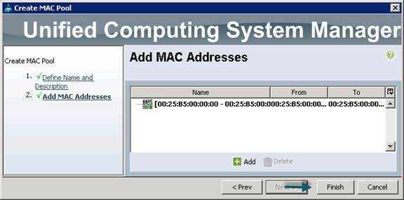
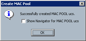
14. When the message box displays, click OK.
Creating a Server Pool
A server pool contains a set of servers. These servers typically share the same characteristics. Those characteristics can be their location in the chassis, or an attribute such as server type, amount of memory, local storage, type of CPU, or local drive configuration. You can manually assign a server to a server pool, or use server pool policies and server pool policy qualifications to automate the assignment
To configure the server pool within the Cisco UCS Manager GUI, complete the following steps:
1. Select the Servers tab in the left pane in the Cisco UCS Manager GUI.
2. Select Pools > root.
3. Right-click the Server Pools.
4. Select Create Server Pool.
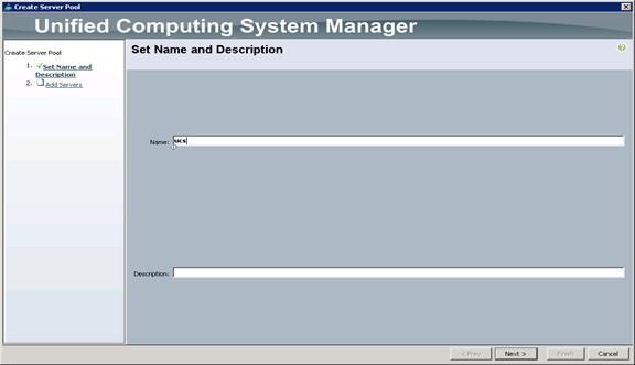
5. Enter your required name (ucs) for the Server Pool in the name text box (Figure 24).
6. (Optional) enter a description for the organization.
7. Click Next > to add the servers.
Figure 24 Set Name and Description
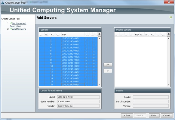
8. Select all the Cisco UCS C240M4SX servers to be added to the server pool that was previously created (ucs), then Click >> to add them to the pool (Figure 25).
9. Click Finish.
10. Click OK and then click Finish.
Creating Policies for Service Profile Templates
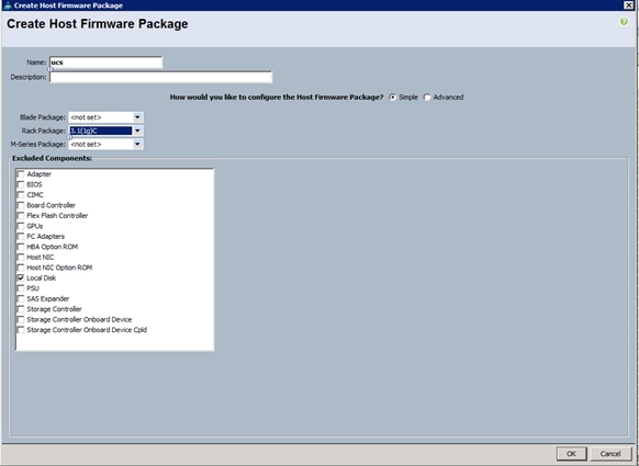
Creating Host Firmware Package Policy
Firmware management policies allow the administrator to select the corresponding packages for a given server configuration. These include adapters, BIOS, board controllers, FC adapters, HBA options, and storage controller properties as applicable.
To create a firmware management policy for a given server configuration using the Cisco UCS Manager GUI, complete the following steps:
1. Select the Servers tab in the left pane in the Cisco UCS Manager GUI.
2. Select Policies > root.
3. Right-click Host Firmware Packages.
4. Select Create Host Firmware Package.
5. Enter the required Host Firmware package name (ucs) (Figure 26).
6. Select Simple radio button to configure the Host Firmware package.
7. Select the appropriate Rack package that has been installed.
8. Click OK to complete creating the management firmware package.
9. Click OK.
Figure 26 Create Host Firmware Package
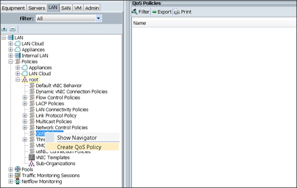
Creating QoS Policies
To create the QoS policy for a given server configuration using the Cisco UCS Manager GUI, complete the following steps:
Platinum Policy
1. Select the LAN tab in the left pane in the Cisco UCS Manager GUI.
2. Select Policies > root.
3. Right-click QoS Policies.
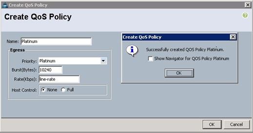
4. Select Create QoS Policy (Figure 27).
5. Enter Platinum as the name of the policy.
6. Select Platinum from the drop down menu.
7. Keep the Burst(Bytes) field set to default (10240).
8. Keep the Rate(Kbps) field set to default (line-rate).
9. Keep Host Control radio button set to default (none).
10. Once the pop-up window appears, click OK to complete the creation of the Policy (Figure 28).
Figure 28 Create QoS Policy Confirmation
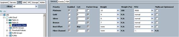
Setting Jumbo Frames
To set Jumbo frames and enable QoS, complete the following steps:
1. Select the LAN tab in the left pane in the Cisco UCSM GUI.
2. Select LAN Cloud > QoS System Class.
3. In the right pane, select the General tab (Figure 29).
4. In the Platinum row, enter 9000 for MTU.
5. Check the Enabled Check box next to Platinum.
6. In the Best Effort row, select none for weight.
7. In the Fiber Channel row, select none for weight.
8. Click Save Changes.
9. Click OK.
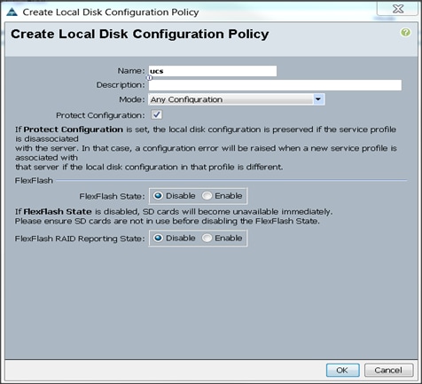
Creating the Local Disk Configuration Policy
To create local disk configuration in the Cisco UCS Manager GUI, complete the following steps:
1. Select the Servers tab on the left pane in the Cisco UCS Manager GUI.
2. Go to Policies > root.
3. Right-click Local Disk Config Policies.
4. Select Create Local Disk Configuration Policy.
5. Enter ucs as the local disk configuration policy name (Figure 30).
6. Change the Mode to Any Configuration. Check the Protect Configuration box.
7. Keep the FlexFlash State field as default (Disable).
8. Keep the FlexFlash RAID Reporting State field as default (Disable).
9. Click OK to complete the creation of the Local Disk Configuration Policy.
10. Click OK.
Figure 30 Create Local Disk Configuration Policy
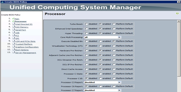
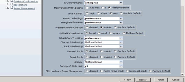
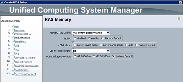
Creating Server BIOS Policy
The BIOS policy feature in Cisco UCS automates the BIOS configuration process. The traditional method of setting the BIOS is manually, and is often error-prone. By creating a BIOS policy and assigning the policy to a server or group of servers, can enable transparency within the BIOS settings configuration.
![]() Note: BIOS settings can have a significant performance impact, depending on the workload and the applications. The BIOS settings listed in this section is for configurations optimized for best performance which can be adjusted based on the application, performance, and energy efficiency requirements.
Note: BIOS settings can have a significant performance impact, depending on the workload and the applications. The BIOS settings listed in this section is for configurations optimized for best performance which can be adjusted based on the application, performance, and energy efficiency requirements.
To create a server BIOS policy using the Cisco UCS Manager GUI, complete the following steps:
1. Select the Servers tab in the left pane in the Cisco UCS Manager GUI.
2. Select Policies > root.
3. Right-click BIOS Policies.
4. Select Create BIOS Policy.
5. Enter your preferred BIOS policy name (ucs).
6. Change the BIOS settings as shown in the following figures.
7. The only changes that need to be made are in the Processor (Figure 31) and RAS Memory settings (Figure 32).
Figure 31 Cisco UCS Manager Processor Settings
Creating the Boot Policy
To create boot policies within the Cisco UCS Manager GUI, complete the following steps:
1. Select the Servers tab in the left pane in the Cisco UCS Manager GUI.
2. Select Policies > root.
3. Right-click the Boot Policies.
4. Select Create Boot Policy (Figure 33).
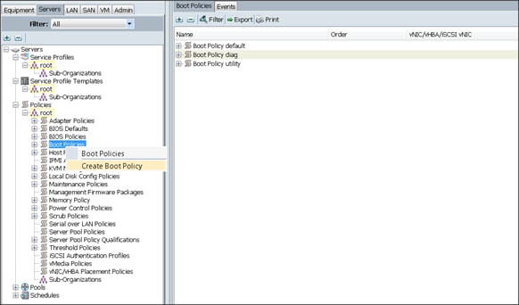
5. Enter ucs as the Boot Policy name (Figure 34).
6. (Optional) enter a description for the boot policy.
7. Keep the Reboot on Boot Order Change check box unchecked.
8. Keep Enforce vNIC/vHBA/iSCSI Name check box checked.
9. Keep Boot Mode Default (Legacy).
10. Expand Local Devices > Add CD/DVD and select Add Local CD/DVD.
11. Expand Local Devices and select Add Local Disk.
12. Expand vNICs and select Add LAN Boot and enter eth0.
13. Click OK to add the Boot Policy.
14. Click OK.
Figure 34 Boot Policy/Add LAN Boot
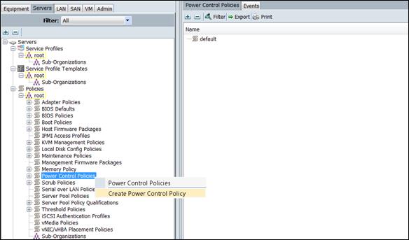
Creating Power Control Policy
To create Power Control policies within the Cisco UCS Manager GUI, complete the following steps:
1. Select the Servers tab in the left pane in the Cisco UCS Manager GUI.
2. Select Policies > root.
3. Right-click the Power Control Policies.
4. Select Create Power Control Policy (Figure 35).
Figure 35 Power Control Policies
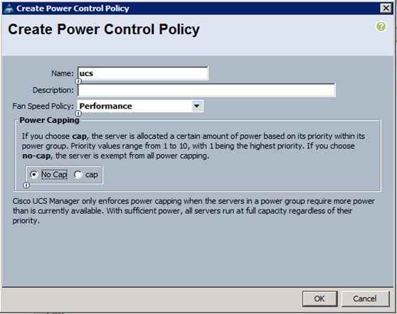
5. Enter ucs as the Power Control policy name (Figure 36).
6. (Optional) enter a description for the boot policy.
7. Select Performance for Fan Speed Policy.
8. Select No cap for Power Capping selection.
9. Click OK to create the Power Control Policy.
10. Click OK.
Figure 36 Create the Power Control Policy
Creating a Service Profile Template
To create a Service Profile Template, complete the following steps:
1. Select the Servers tab in the left pane in the UCSM GUI.
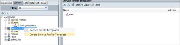
2. Right-click Service Profile Templates.
3. Select Create Service Profile Template (Figure 37).
Figure 37 Create Service Profile Template
The Create Service Profile Template window appears.
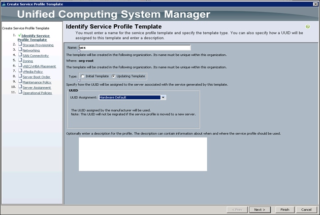
To identify the service profile template, complete the following steps (Figure 38):
1. Name the service profile template as ucs. Select the Updating Template radio button.
2. In the UUID section, select Hardware Default as the UUID pool.
3. Click Next to continue to the next section.
Figure 38 Identify the Service Profile Template
Configuring the Storage Provisioning for the Template
To configure Storage policies, complete the following steps (Figure 39):
1. Go to the Local Disk Configuration Policy tab, and select ucs for the Local Storage.
2. Click Next to continue to the next section.
Figure 39 Storage Provisioning
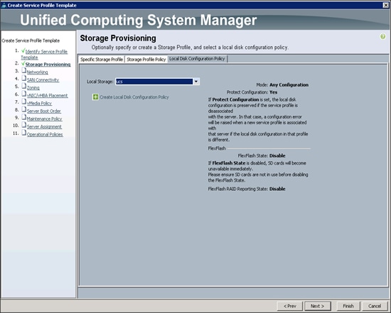
3. Click Next. The Networking window appears (Figure 40).
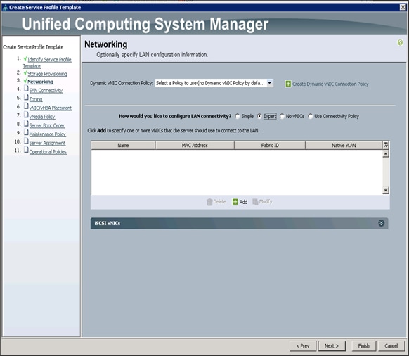
Configuring Network Settings for the Template
1. Keep the Dynamic vNIC Connection Policy field at the default.
2. Select Expert radio button for the option how would you like to configure LAN connectivity?
3. Click Add to add a vNIC to the template.
4. The Create vNIC window displays. Name the vNIC as eth0. (Figure 41)
5. Select ucs in the Mac Address Assignment pool.
6. Select the Fabric A radio button and check the Enable failover check box for the Fabric ID.
7. Check the VLAN36 check box for VLANs and select the Native VLAN radio button.
8. Select MTU size as 9000.
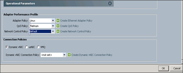
9. Select adapter policy as Linux.
10. Select QoS Policy as Platinum.
11. Keep the Network Control Policy as Default.
12. Click OK.


13. Click Add to add a vNIC to the template.
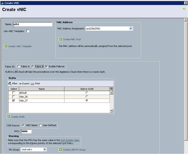
14. The Create vNIC window displays. Name the vNIC as eth1.
15. Select ucs in the Mac Address Assignment pool.
16. Select the Fabric B radio button and check the Enable failover check box for the Fabric ID.
17. Check the VLAN37 check box for VLANs and select the Native VLAN radio button.
18. Set the MTU size to 9000.
19. Select Linux for the Adapter Policy.
20. Select Platinum for the QoS Policy.
21. Keep the Network Control Policy set to Default.
22. Click OK.
Figure 42 Create vNIC
23. Click Next to continue with SAN Connectivity (Figure 43).
24. Select no vHBAs for, How would you like to configure SAN Connectivity?
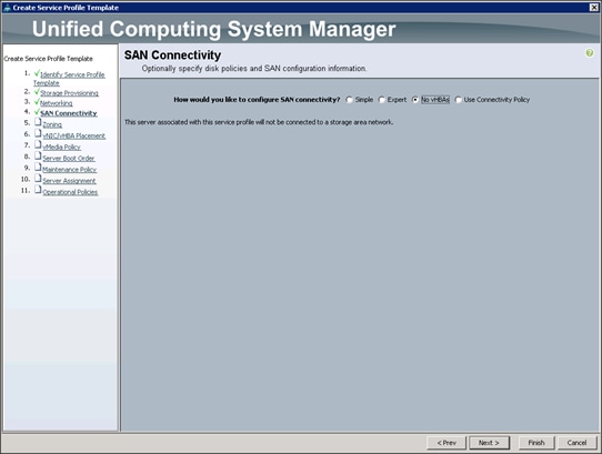
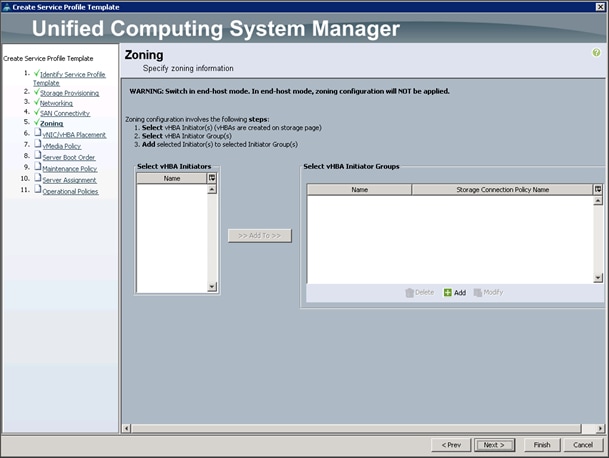
25. Click Next to continue with Zoning (Figure 44).
26. Click Next to continue with vNIC/vHBA placement (Figure 45).
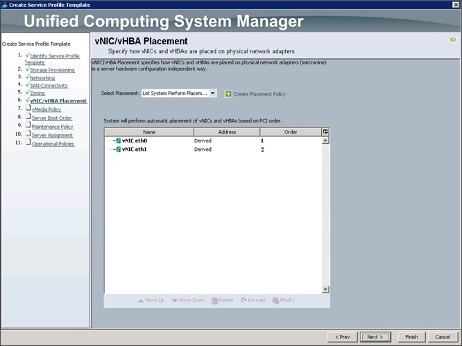
27. Click Next to configure vMedia Policy.
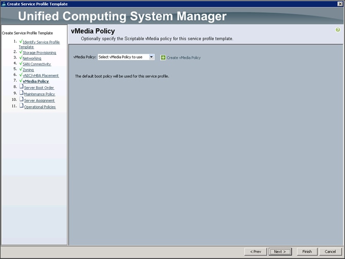
Configuring the vMedia Policy for the Template
1. Once the vMedia Policy window appears (Figure 46), click Next to go to the next section.
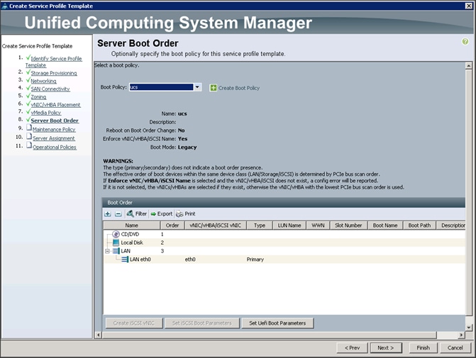
Configuring Server Boot Order for the Template
To set the boot order for the servers, complete the following steps (Figure 47):
1. Select ucs in the Boot Policy name field.
2. Review to make sure that all of the boot devices were created and identified.
3. Verify that the boot devices are in the correct boot sequence.
4. Click OK.
5. Click Next to continue to the next section.
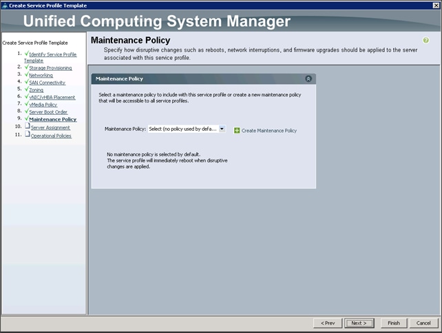
6. In the Maintenance Policy window, apply the maintenance policy.
7. Keep the Maintenance Policy at no policy used by default (Figure 48). Click Next to continue to the next section.
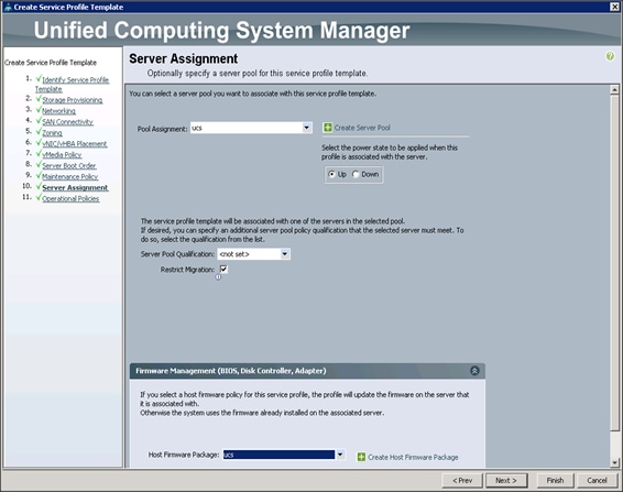
Configuring Server Assignment for the Template
To assign the servers to the pool, complete the following steps:
1. Select ucs for the Pool Assignment field (Figure 49).
2. Select the power state to be Up.
3. Keep the Server Pool Qualification field set to <not set>.
4. Check the Restrict Migration check box.
5. Select ucs in Host Firmware Package.
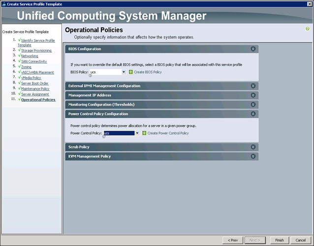
Configuring Operational Policies for the Template
In the Operational Policies window (Figure 50), complete the following steps:
1. Select ucs in the BIOS Policy field.
2. Select ucs in the Power Control Policy field.
Figure 50 Operational Policies Window
3. Click Finish to create the Service Profile template.
4. Click OK in the pop-up window to proceed.
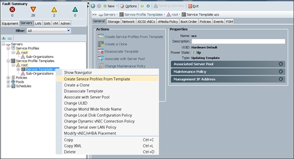
5. Select the Servers tab in the left pane of the UCS Manager GUI (Figure 51).
6. Go to Service Profile Templates > root.
7. Right-click Service Profile Templates ucs.
8. Select Create Service Profiles From Template.
Figure 51 Create Service Profiles From Template
The Create Service Profiles from Template window appears (Figure 52).
Figure 52 Create Service Profiles from Template
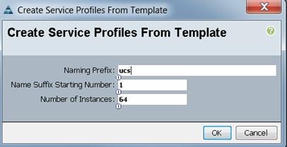
Association of the Service Profiles will take place automatically.
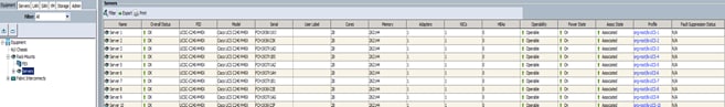
The final Cisco UCS Manager window is shown in below in Figure 53.
Figure 53 Cisco UCS Manager Window
Installing Red Hat Enterprise Linux 7.2
The following section provides detailed procedures for installing Red Hat Enterprise Linux 7.2 using Software RAID (OS based Mirroring) on Cisco UCS C240 M4 servers. There are multiple ways to install the Red Hat Linux operating system. The installation procedure described in this deployment guide uses KVM console and virtual media from Cisco UCS Manager.
![]() Note: This requires RHEL 7.2 DVD/ISO for the installation
Note: This requires RHEL 7.2 DVD/ISO for the installation
To install the Red Hat Linux 7.2 operating system, complete the following steps:
1. Log in to the Cisco UCS 6296 Fabric Interconnect and launch the Cisco UCS Manager application.
2. Select the Equipment tab.
3. In the navigation pane expand Rack-Mounts and then Servers.
4. Right click on the server and select KVM Console (Figure 54).
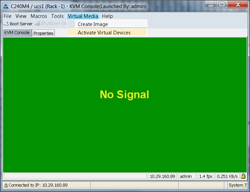
5. In the KVM window, select the Virtual Media tab (Figure 55).
Figure 54 Launch the KVM Console
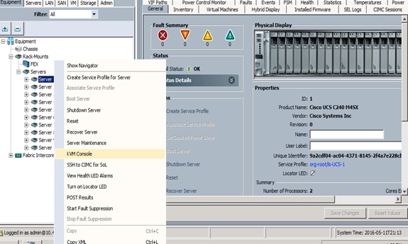
6. Click the Activate Virtual Devices found in Virtual Media tab (Figure 55).
7. In the KVM window, select the Virtual Media tab and click the Map CD/DVD. (Figure 56)
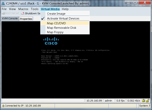
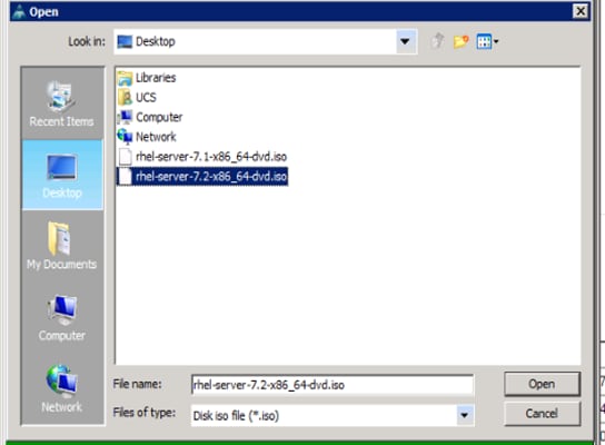
8. Browse to the Red Hat Enterprise Linux Server 7.2 installer ISO image file (Figure 57).
![]() Note: The Red Hat Enterprise Linux 7.2 DVD is assumed to be on the client machine.
Note: The Red Hat Enterprise Linux 7.2 DVD is assumed to be on the client machine.
9. Click Open to add the image to the list of virtual media.
Figure 57 Browse to the ISO Image File
10. In the KVM window, select the KVM tab to monitor during boot.
11. In the KVM window, select the Macros > Static Macros > Ctrl-Alt-Del button in the upper left corner.
12. Click OK.
13. Click OK to reboot the system.
14. On reboot, the machine detects the presence of the Red Hat Enterprise Linux Server 7.2 install media.
15. Select the Install or Upgrade an Existing System.
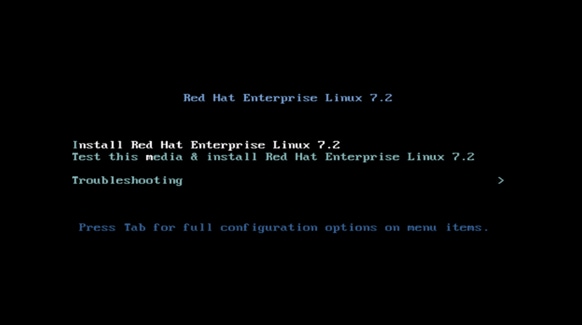
16. Skip the Media test and start the installation. Select the language of installation and click Continue.

17. Select Date and time, which pops up another window as shown below:
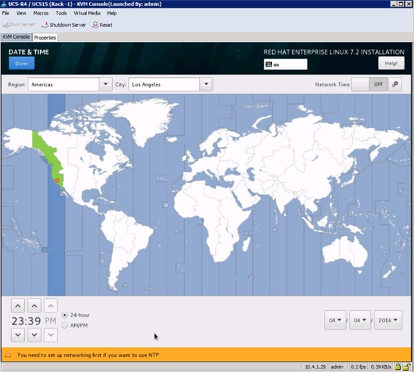
18. Select the location on the map, set the time and click Done.
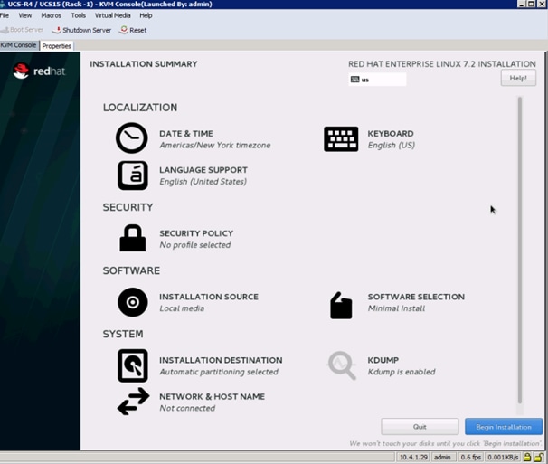
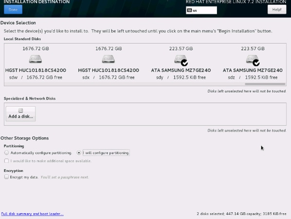
19. Click on Installation Destination.
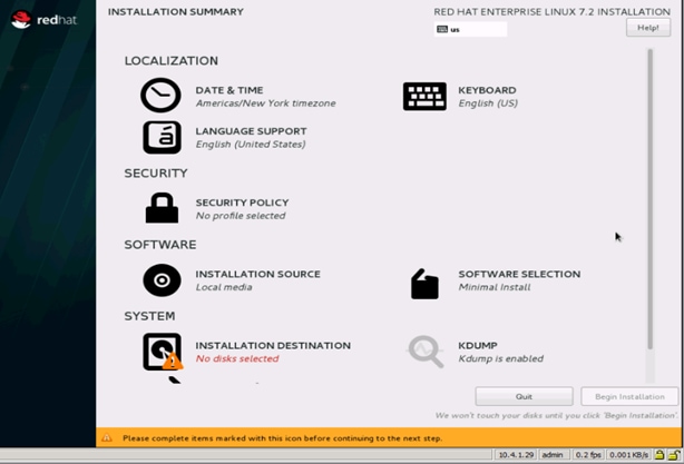
20. This opens a new window with the boot disks. Make the selection, and choose I will configure partitioning. Click Done.
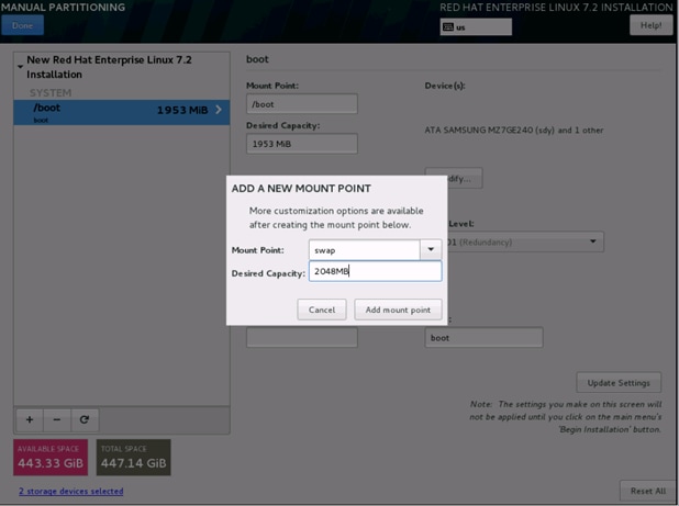
21. This opens a window for creating the partitions. Click on the + sign to add a new partition as shown below, boot partition of size 2048 MB.
22. Click Add MountPoint to add the partition.
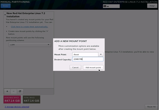
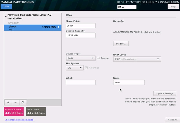
23. Change the Device type to RAID and make sure the RAID Level is RAID1 (Redundancy) and click on Update Settings to save the changes.
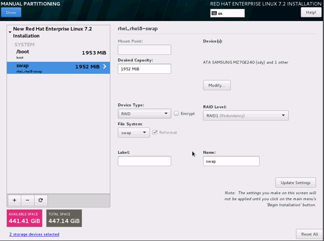
24. Click on the + sign to create the swap partition of size 2048 MB as shown below.
25. Change the Device type to RAID and RAID level to RAID1 (Redundancy) and click on Update Settings.
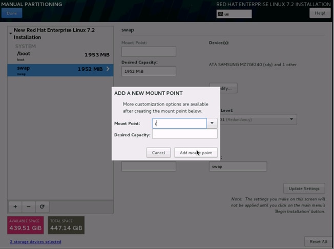
26. Click + to add the / partition. The size can be left empty so it uses the remaining capacity and click Add Mountpoint.
27. Change the Device type to RAID and RAID level to RAID1 (Redundancy). Click Update Settings.
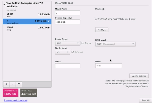
28. Click Done to go back to the main screen and continue the Installation.
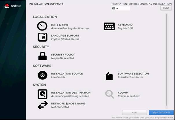
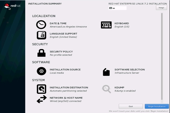
29. Click on Software Selection.

30. Select Infrastructure Server and select the Add-Ons as noted below. Click Done.

31. Click on Network and Hostname and configure Hostname and Networking for the Host.
32. Type in the hostname as shown below.
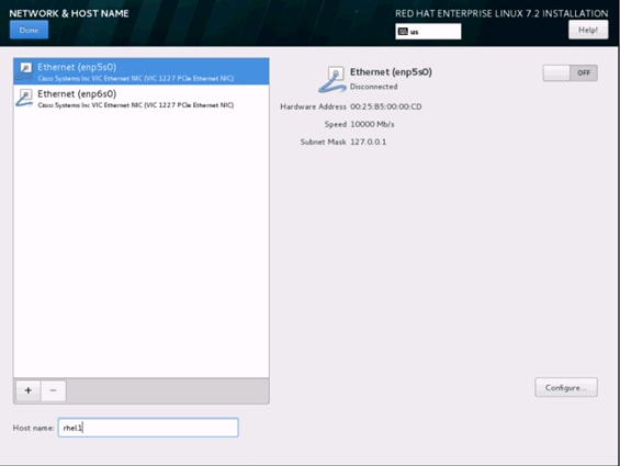
33. Click on Configure to open the Network Connectivity window. Click on IPV4Settings.
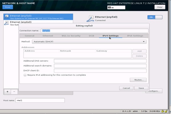
34. Change the Method to Manual and click Add to enter the IP Address, Netmask and Gateway details.
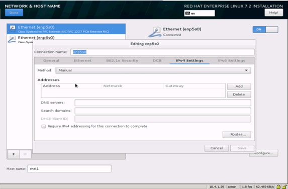
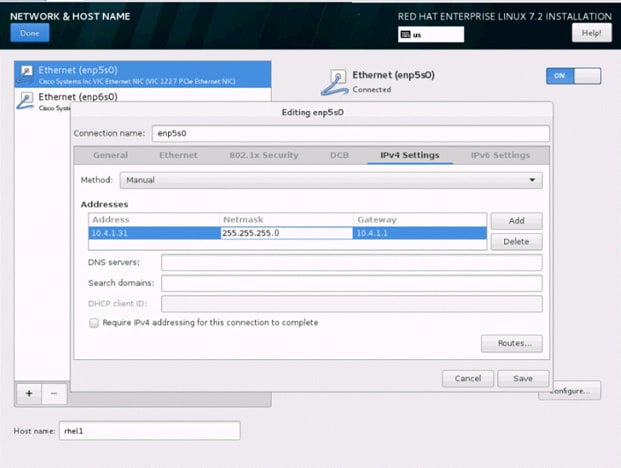
35. Click Save, update the hostname and turn Ethernet ON. Click Done to return to the main menu.
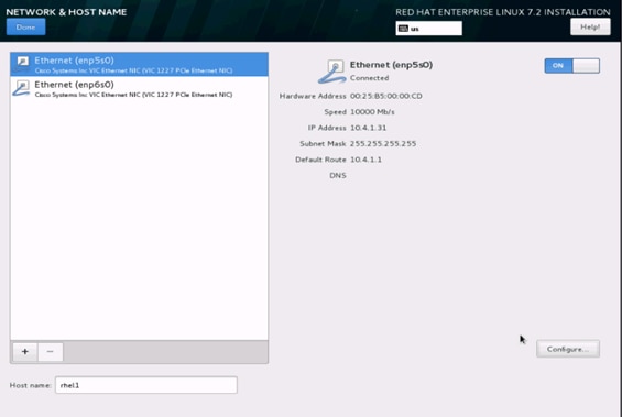
Note: Follow similar steps to assign IP for enp6s0 on different subnet in this case 10.5.1.31
36. Click Begin Installation in the main menu.
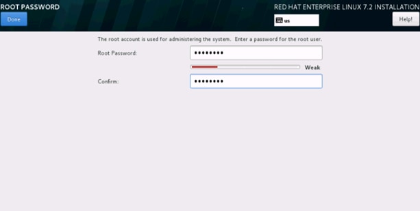
37. Select Root Password in the User Settings.
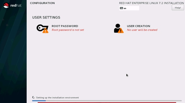
38. Enter the Root Password and click done.
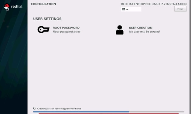
39. Once the installation is complete reboot the system.
40. Repeat steps 1 to 39 to install Red Hat Enterprise Linux 7.2 on Servers 2 through 64.
![]() Note: The OS installation and configuration of the nodes that is mentioned above can be automated through PXE boot or third party tools.
Note: The OS installation and configuration of the nodes that is mentioned above can be automated through PXE boot or third party tools.
The hostnames and their corresponding IP addresses are shown in Table 6.
Table 6 Hostnames and IP Addresses
| Hostname |
eth0 |
eth1 |
| rhel1 |
10.4.1.31 |
10.5.1.31 |
| rhel2 |
10.4.1.32 |
10.5.1.32 |
| rhel3 |
10.4.1.33 |
10.5.1.33 |
| rhel4 |
10.4.1.34 |
10.5.1.34 |
| rhel1 |
10.4.1.35 |
10.5.1.35 |
| rhel6 |
10.4.1.36 |
10.5.1.36 |
| rhel7 |
10.4.1.37 |
10.5.1.37 |
| rhel8 |
10.4.1.38 |
10.5.1.38 |
| rhel9 |
10.4.1.39 |
10.5.1.39 |
| rhel10 |
10.4.1.40 |
10.5.1.40 |
| rhel11 |
10.4.1.41 |
10.5.1.41 |
| rhel12 |
10.4.1.42 |
10.5.1.42 |
| rhel13 |
10.4.1.43 |
10.5.1.43 |
| rhel14 |
10.4.1.44 |
10.5.1.44 |
| rhel15 |
10.4.1.45 |
10.5.1.45 |
| rhel16 |
10.4.1.46 |
10.5.1.46 |
| … |
… |
… |
| rhel64 |
10.4.1.94 |
10.5.1.94 |
![]() Note: With MapR supporting multiple NICs, Hadoop will use multiple IP subnets for its data traffic, vlan36 and vlan37 can be configured to carry Hadoop data traffic allowing the use of both the fabric interconnects (10 GigE on each fabric allowing 20Gbps active-active connectivity).
Note: With MapR supporting multiple NICs, Hadoop will use multiple IP subnets for its data traffic, vlan36 and vlan37 can be configured to carry Hadoop data traffic allowing the use of both the fabric interconnects (10 GigE on each fabric allowing 20Gbps active-active connectivity).
Post OS Install Configuration
Choose one of the nodes of the cluster or a separate node as the Admin Node for management such as MapR installation, cluster parallel shell, creating a local Red Hat repo and others. In this document, we use rhel1 for this purpose.
Setting Up Password-less Login
To manage all of the clusters nodes from the admin node password-less login needs to be setup. It assists in automating common tasks with clustershell (clush, a cluster wide parallel shell), and shell-scripts without having to use passwords.
Once Red Hat Linux is installed across all the nodes in the cluster, follow the steps below in order to enable password-less login across all the nodes.
1. Login to the Admin Node (rhel1).
#ssh 10.4.1.31
2. Run the ssh-keygen command to create both public and private keys on the admin node.
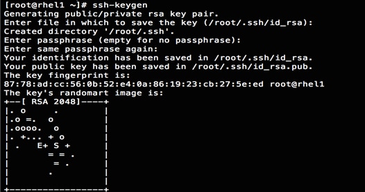
3. Then run the following command from the admin node to copy the public key id_rsa.pub to all the nodes of the cluster. ssh-copy-id appends the keys to the remote-host’s .ssh/authorized_keys.
#for IP in {31..94}; do echo -n "$IP -> "; ssh-copy-id -i ~/.ssh/id_rsa.pub 10.4.1.$IP; done
4. Enter yes for Are you sure you want to continue connecting (yes/no)?
5. Enter the password of the remote host.
Configuring /etc/hosts
Setup /etc/hosts on the Admin node; this is a pre-configuration to setup DNS as shown in the next section.
To create the host file on the admin node, complete the following steps:
1. Populate the host file with IP addresses and corresponding hostnames on the Admin node (rhel1) and other nodes as follows:
2. On the Admin Node (rhel1):
#vi /etc/hosts
127.0.0.1 localhost localhost.localdomain localhost4 \ localhost4.localdomain4
::1 localhost localhost.localdomain localhost6 \ localhost6.localdomain6
10.4.1.31 rhel1
10.4.1.32 rhel2
10.4.1.33 rhel3
10.4.1.34 rhel4
10.4.1.35 rhel5
10.4.1.36 rhel6
10.4.1.37 rhel7
10.4.1.38 rhel8
10.4.1.39 rhel9
10.4.1.40 rhel10
10.4.1.41 rhel11
10.4.1.42 rhel12
10.4.1.43 rhel13
10.4.1.44 rhel14
10.4.1.45 rhel15
10.4.1.46 rhel16
...
10.4.1.94 rhel64
10.5.1.31 rhel1-2
10.5.1.32 rhel2-2
10.5.1.33 rhel3-2
10.5.1.34 rhel4-2
10.5.1.35 rhel5-2
10.5.1.36 rhel6-2
10.5.1.37 rhel7-2
10.5.1.38 rhel8-2
10.5.1.39 rhel9-2
10.5.1.40 rhel10-2
10.5.1.41 rhel11-2
10.5.1.42 rhel12-2
10.5.1.43 rhel13-2
10.5.1.44 rhel14-2
10.5.1.45 rhel15-2
10.5.1.46 rhel16-2
...
10.5.1.94 rhel64-2
Creating a Red Hat Enterprise Linux (RHEL) 7.2 Local Repo
To create a repository using RHEL DVD or ISO on the admin node (in this deployment rhel1 is used for this purpose), create a directory with all the required RPMs, run the createrepo command and then publish the resulting repository.
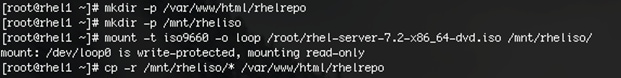
1. Log on to rhel1. Create a directory that would contain the repository.
#mkdir -p /var/www/html/rhelrepo
2. Copy the contents of the Red Hat DVD to /var/www/html/rhelrepo
3. Alternatively, if you have access to a Red Hat ISO Image, Copy the ISO file to rhel1.
4. And login back to rhel1 and create the mount directory.
#scp rhel-server-7.2-x86_64-dvd.iso rhel1:/root/
#mkdir -p /mnt/rheliso
#mount -t iso9660 -o loop /root/rhel-server-7.2-x86_64-dvd.iso /mnt/rheliso/
5. Copy the contents of the ISO to the /var/www/html/rhelrepo directory.
#cp -r /mnt/rheliso/* /var/www/html/rhelrepo
6. Now on rhel1 create a .repo file to enable the use of the yum command.
#vi /var/www/html/rhelrepo/rheliso.repo
[rhel7.2]
name=Red Hat Enterprise Linux 7.2
baseurl=http://10.4.1.31/rhelrepo
gpgcheck=0
enabled=1
7. Now copy rheliso.repo file from /var/www/html/rhelrepo to /etc/yum.repos.d on rhel1.
#cp /var/www/html/rhelrepo/rheliso.repo /etc/yum.repos.d/
![]() Note: Based on this repo file yum requires httpd to be running on rhel1 for other nodes to access the repository.
Note: Based on this repo file yum requires httpd to be running on rhel1 for other nodes to access the repository.
8. To make use of repository files on rhel1 without httpd, edit the baseurl of repo file /etc/yum.repos.d/rheliso.repo to point repository location in the file system.
![]() Note: This step is needed to install software on Admin Node (rhel1) using the repo (such as httpd, create-repo, etc.)
Note: This step is needed to install software on Admin Node (rhel1) using the repo (such as httpd, create-repo, etc.)
#vi /etc/yum.repos.d/rheliso.repo
[rhel7.2]
name=Red Hat Enterprise Linux 7.2
baseurl=file:///var/www/html/rhelrepo
gpgcheck=0
enabled=1
Creating the Red Hat Repository Database.
1. Install the createrepo package on admin node (rhel1). Use it to regenerate the repository database(s) for the local copy of the RHEL DVD contents.
#yum -y install createrepo
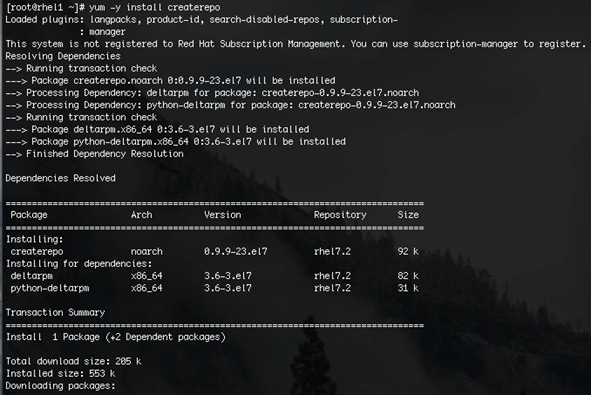
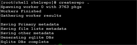
2. Run createrepo on the RHEL repository to create the repo database on admin node
#cd /var/www/html/rhelrepo
#createrepo .
Setting up ClusterShell
ClusterShell (or clush) is the cluster-wide shell that runs commands on several hosts in parallel.
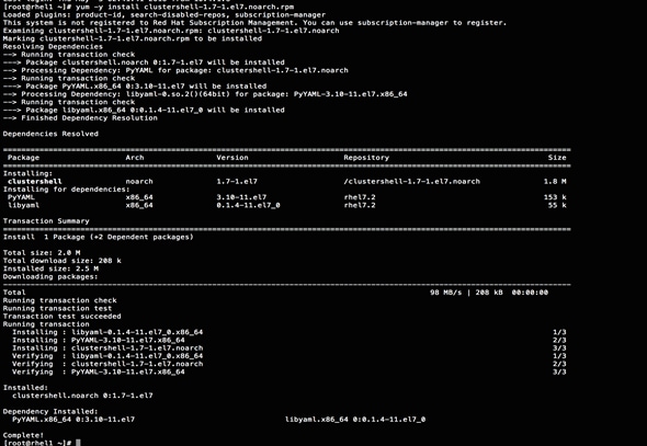
1. From the system connected to the Internet download Cluster shell (clush) and install it on rhel1. Cluster shell is available from EPEL (Extra Packages for Enterprise Linux) repository.
#scp clustershell-1.7-1.el7.noarch.rpm rhel1:/root/
2. Login to rhel1 and install cluster shell.
3. #yum –y install clustershell-1.7-1.el7.noarch.rpm
4. Edit /etc/clustershell/groups.d/local.cfg file to include hostnames for all the nodes of the cluster. This set of hosts is taken when running clush with the ‘-a’ option.
5. For 64 node cluster as in our CVD, set groups file as follows,
#vi /etc/clustershell/groups.d/local.cfg
![]()
all: rhel[1-64]
![]() Note: For more information and documentation on ClusterShell, visit https://github.com/cea-hpc/clustershell/wiki/UserAndProgrammingGuide.
Note: For more information and documentation on ClusterShell, visit https://github.com/cea-hpc/clustershell/wiki/UserAndProgrammingGuide.
![]() Note: Clustershell will not work if not ssh to the machine earlier (as it requires to be in known_hosts file), for instance, as in the case below for rhel<host>.
Note: Clustershell will not work if not ssh to the machine earlier (as it requires to be in known_hosts file), for instance, as in the case below for rhel<host>.
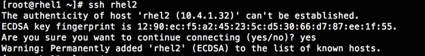
Installing httpd
Setting up RHEL repo on the admin node requires httpd. To set up RHEL repository on the admin node, complete the following steps:
1. Install httpd on the admin node to host repositories.
The Red Hat repository is hosted using HTTP on the admin node, this machine is accessible by all the hosts in the cluster.
#yum –y install httpd
2. Add ServerName and make the necessary changes to the server configuration file.
#vi /etc/httpd/conf/httpd.conf
ServerName 10.4.1.31:80

3. Start httpd
#service httpd start
#chkconfig httpd on
Set Up all Nodes to use the RHEL Repository
![]() Note: Based on this repo file yum requires httpd to be running on rhel1 for other nodes to access the repository.
Note: Based on this repo file yum requires httpd to be running on rhel1 for other nodes to access the repository.
1. Copy the rheliso.repo to all the nodes of the cluster.
#clush –w rhel[2-64] -c /var/www/html/rhelrepo/rheliso.repo --dest=/etc/yum.repos.d/
![]()
2. Also copy the /etc/hosts file to all nodes.
3. #clush –w rhel[2-64] –c /etc/hosts –-dest=/etc/hosts
4. Purge the yum caches after this
#clush -a -B yum clean all
#clush –a –B yum repolist
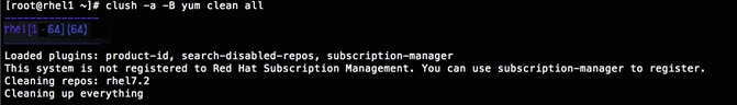
![]() Note: While suggested configuration is to disable SELinux as shown below, if for any reason SELinux needs to be enabled on the cluster, then ensure to run the following to make sure that the httpd is able to read the Yum repofiles.
Note: While suggested configuration is to disable SELinux as shown below, if for any reason SELinux needs to be enabled on the cluster, then ensure to run the following to make sure that the httpd is able to read the Yum repofiles.
#chcon -R -t httpd_sys_content_t /var/www/html/
Configuring DNS
This section details setting up DNS using dnsmasq as an example based on the /etc/hosts configuration setup in the earlier section.
To create the host file across all the nodes in the cluster, complete the following steps:
1. Disable Network manager on all nodes:
#clush -a -b service NetworkManager stop
#clush -a -b chkconfig NetworkManager off
2. Update /etc/resolv.conf file to point to Admin Node:
#vi /etc/resolv.conf
nameserver 10.4.1.31
![]() Note: This step is needed if setting up dnsmasq on Admin node. Otherwise this file should be updated with the correct nameserver.
Note: This step is needed if setting up dnsmasq on Admin node. Otherwise this file should be updated with the correct nameserver.
![]() Note: Alternatively #systemctl start NetworkManager.service can be used to start the service. #systemctl stop NetworkManager.service can be used to stop the service. Use #systemctl disable NetworkManager.service to stop a service from being automatically started at boot time.
Note: Alternatively #systemctl start NetworkManager.service can be used to start the service. #systemctl stop NetworkManager.service can be used to stop the service. Use #systemctl disable NetworkManager.service to stop a service from being automatically started at boot time.
3. Install and Start dnsmasq on Admin node:
#service dnsmasq start
#chkconfig dnsmasq on
4. Deploy /etc/resolv.conf from the admin node (rhel1) to all the nodes via the following clush command:
#clush -a -B -c /etc/resolv.conf
![]() Note: A clush copy without –dest copies to the same directory location as the source-file directory
Note: A clush copy without –dest copies to the same directory location as the source-file directory
5. Ensure DNS is working fine by running the following command on Admin node and any data-node:
[root@rhel2 ~]# nslookup rhel1
Server: 10.4.1.31
Address: 10.4.1.31#53
Name: rhel1
Address: 10.4.1.31 ç
![]() Note: yum install –y bind-utils will need to be run for nslookup to utility to run.
Note: yum install –y bind-utils will need to be run for nslookup to utility to run.
Upgrading the Cisco Network Driver for VIC1227
The latest Cisco Network driver is required for performance and updates. The latest drivers can be downloaded from the link below:
https://software.cisco.com/download/release.html?mdfid=286281356&reltype=latest&relind=AVAILABLE&dwnld=true&softwareid=283853158&rellifecycle=&atcFlag=N&release=2.0%289b%29&dwldImageGuid=84C2FF3BB579A1BF32F7227C59F6DF886CEDBE99&flowid=71443
1. In the ISO image, the required driver kmod-enic-2.3.0.20-rhel7u2.el7.x86_64.rpm can be located at \Linux\Network\Cisco\VIC\RHEL\RHEL7.2.
2. From a node connected to the Internet, download, extract and transfer kmod-enic-2.3.0.20-rhel7u2.el7.x86_64.rpm to rhel1 (admin node).
3. Install the rpm on all nodes of the cluster using the following clush commands. For this example the rpm is assumed to be in present working directory of rhel1.
[root@rhel1 ~]# clush -a -b -c kmod-enic-2.3.0.20-rhel7u2.el7.x86_64.rpm
[root@rhel1 ~]# clush -a -b "rpm –ivh kmod-enic-2.3.0.20-rhel7u2.el7.x86_64.rpm"
4. Ensure that the above installed version of kmod-enic driver is being used on all nodes by running the command "modinfo enic" on all nodes:
[root@rhel1 ~]# clush -a -B "modinfo enic | head -5"
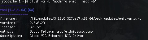
5. Also it is recommended to download the kmod-megaraid driver for higher performance , the RPM can be found in the same package at \Linux\Storage\LSI\Cisco_Storage_12G_SAS_RAID_controller\RHEL\RHEL7.2
Setting up JAVA
MapR requires Java 8. To install Java 8, complete the following steps:
1. Download jdk-8u91-linux-x64.rpm from oracle.com and scp the rpm to (http://www.oracle.com/technetwork/java/javase/downloads/jdk8-downloads-2133151.html ) to admin node (rhel1).
2. Run the following commands on admin node (rhel1) to install and setup java on all nodes.
3. Copy JDK rpm to all nodes.
clush -a -b -c /root/jdk-8u91-linux-x64.rpm --dest=/root/
4. Extract and Install JDK on all nodes.
clush -a -b rpm -ivh /root/jdk-8u91-linux-x64.rpm
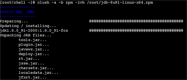
5. Create the following files java-set-alternatives.sh and java-home.sh on the admin node (rhel1).
vi java-set-alternatives.sh
#!/bin/bash
for item in java javac javaws jar jps javah javap jcontrol jconsole jdb; do
rm -f /var/lib/alternatives/$item
alternatives --install /usr/bin/$item $item /usr/java/jdk1.8.0_91/bin/$item 9
alternatives --set $item /usr/java/jdk1.8.0_91/bin/$item
done
vi java-home.sh
export JAVA_HOME=/usr/java/jdk1.8.0_91
6. Make the two java scripts created above executable.
chmod 755 ./java-set-alternatives.sh ./java-home.sh
7. Copying java-set-alternatives.sh to all nodes.
clush -b -a -c ./java-set-alternatives.sh --dest=/root/
8. Setup Java Alternatives.
clush -b -a ./java-set-alternatives.sh
9. Ensure correct java is setup on all nodes (should point to newly installed java path).
clush -b -a "alternatives --display java | head -2"
10. Setup JAVA_HOME on all nodes.
clush -b -a -c ./java-home.sh --dest=/etc/profile.d
11. Display JAVA_HOME on all nodes.
clush -a -b "echo \$JAVA_HOME"

12. Display current java –version.
clush -B -a java -version
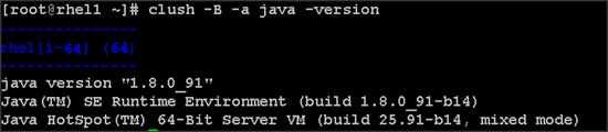
NTP Configuration
The Network Time Protocol (NTP) is used to synchronize the time of all the nodes within the cluster. The Network Time Protocol daemon (ntpd) sets and maintains the system time of day in synchronism with the timeserver located in the admin node (rhel1). Configuring NTP is critical for any Hadoop Cluster. If server clocks in the cluster drift out of sync, serious problems will occur with HBase and other services.
#clush –a –b "yum –y install ntp"
![]() Note: Installing an internal NTP server keeps your cluster synchronized even when an outside NTP server is inaccessible.
Note: Installing an internal NTP server keeps your cluster synchronized even when an outside NTP server is inaccessible.
1. Configure /etc/ntp.conf on the admin node only with the following contents:
#vi /etc/ntp.conf
driftfile /var/lib/ntp/drift
restrict 127.0.0.1
restrict -6 ::1
server 127.127.1.0
fudge 127.127.1.0 stratum 10
includefile /etc/ntp/crypto/pw
keys /etc/ntp/keys
2. Create /root/ntp.conf on the admin node and copy it to all nodes:
#vi /root/ntp.conf
server 10.4.1.31
driftfile /var/lib/ntp/drift
restrict 127.0.0.1
restrict -6 ::1
includefile /etc/ntp/crypto/pw
keys /etc/ntp/keys
3. Copy ntp.conf file from the admin node to /etc of all the nodes by executing the following command in the admin node (rhel1):
#for SERVER in {32..94}; do scp /root/ntp.conf 10.4.1.$SERVER:/etc/ntp.conf; done
![]()
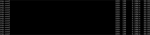
![]() Note: Instead of the above for loop, this could be run as a clush command with "–w"option.
Note: Instead of the above for loop, this could be run as a clush command with "–w"option.
#clush -w rhel[2-64] –b –c /root/ntp.conf --dest=/etc
4. Run the following to syncronize the time and restart NTP daemon on all nodes.
#clush -a -b "service ntpd stop"
#clush -a -b "ntpdate rhel1"
#clush -a -b "service ntpd start"
5. Ensure restart of NTP daemon across reboots:
#clush –a –b "systemctl enable ntpd"
Alternatively, the new Chrony service can be installed, that is quicker to synchronize clocks in mobile and virtual systems.
1. Install the Chrony service:
# yum install -y chrony
2. Activate the Chrony service at boot:
3. # systemctl enable chronyd
4. Start the Chrony service:
# systemctl start chronyd
The Chrony configuration is in the /etc/chrony.conf file, configured similar to /etc/ntp.conf.
Enabling Syslog
Syslog must be enabled on each node to preserve logs regarding killed processes or failed jobs. Modern versions such as syslog-ng and rsyslog are possible, making it more difficult to be sure that a syslog daemon is present. One of the following commands should suffice to confirm that the service is properly configured:
#clush -B -a rsyslogd –v
#clush -B -a service rsyslog status
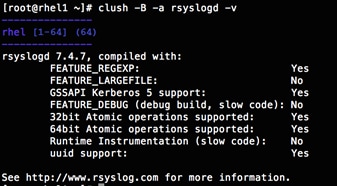
Setting ulimit
On each node, ulimit -n specifies the number of inodes that can be opened simultaneously. With the default value of 1024, the system appears to be out of disk space and shows no inodes available. This value should be set to 64000 on every node.
Higher values are unlikely to result in an appreciable performance gain.
1. For setting the ulimit on Redhat, edit /etc/security/limits.conf on admin node rhel1 and add the following lines:
root soft nofile 64000
root hard nofile 64000

2. Copy the /etc/security/limits.conf file from admin node (rhel1) to all the nodes using the following command.
#clush -a -b -c /etc/security/limits.conf --dest=/etc/security/
![]()
3. Check that the /etc/pam.d/su file contains the following settings:
#%PAM-1.0
auth sufficient pam_rootOK.so
# Uncomment the following line to implicitly trust users in the "wheel" group.
#auth sufficient pam_wheel.so trust use_uid
# Uncomment the following line to require a user to be in the "wheel" group.
#auth required pam_wheel.so use_uid
auth include system-auth
account sufficient pam_succeed_if.so uid = 0 use_uid quiet
account include system-auth
password include system-auth
session include system-auth
session optional pam_xauth.so
![]() Note: The ulimit values are applied on a new shell, running the command on a node on an earlier instance of a shell will show old values.
Note: The ulimit values are applied on a new shell, running the command on a node on an earlier instance of a shell will show old values.
Disabling SELinux
SELinux must be disabled during the install procedure and cluster setup. SELinux can be enabled after installation and while the cluster is running.
1. SELinux can be disabled by editing /etc/selinux/config and changing the SELINUX line to SELINUX=disabled. The following command will disable SELINUX on all nodes.
#clush -a -b "sed –i 's/SELINUX=enforcing/SELINUX=disabled/g' /etc/selinux/config"
![]()
#clush –a –b "setenforce 0"
![]() Note: The above command may fail if SELinux is already disabled.
Note: The above command may fail if SELinux is already disabled.
2. Reboot the machine, if needed for SELinux to be disabled incase it does not take effect. It can checked using:
#clush –a –b sestatus
Set TCP Retries
Adjusting the tcp_retries parameter for the system network enables faster detection of failed nodes. Given the advanced networking features of UCS, this is a safe and recommended change (failures observed at the operating system layer are most likely serious rather than transitory). On each node, set the number of TCP retries to 5 can help detect unreachable nodes with less latency.
1. Edit the file /etc/sysctl.conf and on admin node rhel1 and add the following lines:
net.ipv4.tcp_retries2=5
2. Copy the /etc/sysctl.conf file from admin node (rhel1) to all the nodes using the following command:
#clush -a -b -c /etc/sysctl.conf --dest=/etc/
3. Load the settings from default sysctl file /etc/sysctl.conf by running.
#clush -B -a sysctl -p
Disabling the Linux Firewall
The default Linux firewall settings are far too restrictive for any Hadoop deployment. Since the UCS Big Data deployment will be in its own isolated network there is no need for that additional firewall.
#clush -a -b " firewall-cmd --zone=public --add-port=80/tcp --permanent"
#clush -a -b "firewall-cmd --reload"
#clush –a –b “systemctl disable firewalld”
Disable Swapping
1. In order to reduce Swapping, run the following on all nodes. Variable vm.swappiness defines how often swap should be used, 60 is default.
#clush -a -b " echo 'vm.swappiness=1' >> /etc/sysctl.conf"
2. Load the settings from default sysctl file /etc/sysctl.conf.
#clush –a –b "sysctl –p"
Disable Transparent Huge Pages
Disabling Transparent Huge Pages (THP) reduces elevated CPU usage caused by THP.
#clush -a -b "echo never > /sys/kernel/mm/transparent_hugepage/enabled”
#clush -a -b "echo never > /sys/kernel/mm/transparent_hugepage/defrag"
1. The above commands must be run for every reboot, so copy this command to /etc/rc.local so they are executed automatically for every reboot.
2. On the Admin node, run the following commands
#rm –f /root/thp_disable
#echo "echo never > /sys/kernel/mm/transparent_hugepage/enabled" >>
/root/thp_disable
#echo "echo never > /sys/kernel/mm/transparent_hugepage/defrag " >>
/root/thp_disable
3. Copy file to each node:
#clush –a –b –c /root/thp_disable
4. Append the content of file thp_disable to /etc/rc.local:
#clush -a -b “cat /root/thp_disable >> /etc/rc.local”
Disable IPv6 Defaults
1. Disable IPv6 as the addresses used are IPv4.
#clush -a -b "echo 'net.ipv6.conf.all.disable_ipv6 = 1' >> /etc/sysctl.conf"
#clush -a -b "echo 'net.ipv6.conf.default.disable_ipv6 = 1' >> /etc/sysctl.conf"
#clush -a -b "echo 'net.ipv6.conf.lo.disable_ipv6 = 1' >> /etc/sysctl.conf"
2. Load the settings from default sysctl file /etc/sysctl.conf.
#clush –a –b "sysctl –p"
Configuring Data Drives
This section describes steps to configure non-OS disk drives as RAID0 using StorCli command as described below. These volumes are going to be used for MapRFS (HDFS supported) Data.
1. From the website download storcli http://www.lsi.com/downloads/Public/RAID%20Controllers/RAID%20Controllers%20Common%20Files/1.14.12_StorCLI.zip
2. Extract the zip file and copy storcli-1.14.12-1.noarch.rpm from the linux directory.
3. Download storcli and its dependencies and transfer to Admin node.
#scp storcli-1.14.12-1.noarch.rpm rhel1:/root/
4. Copy storcli rpm to all the nodes using the following commands:
#clush -a -b -c /root/storcli-1.14.12-1.noarch.rpm --dest=/root/
5. Run the below command to install storcli on all the nodes:
#clush -a -b “rpm -ivh storcli-1.14.12-1.noarch.rpm”
6. Run the below command to copy storcli64 to root directory.
#cd /opt/MegaRAID/storcli/
#cp storcli64 /root/

7. Copy storcli64 to all the nodes using the following commands:
#clush -a -b -c /root/storcli64 --dest=/root/
8. Run the following command as root user on rhel1
# clush –a –B “storcli64 -cfgeachdskraid0 WB RA direct NoCachedBadBBU strpsz1024 -a0”
WB: Write back
RA: Read Ahead
NoCachedBadBBU: Do not write cache when the BBU is bad.
Strpsz1024: Strip Size of 1024K
![]() Note: The command above will not override any existing configuration. To clear and reconfigure existing configurations refer to Embedded MegaRAID Software Users Guide available at www.lsi.com.
Note: The command above will not override any existing configuration. To clear and reconfigure existing configurations refer to Embedded MegaRAID Software Users Guide available at www.lsi.com.
Cluster Verification and Micro-Benchmark
This section provides a set of micro-benchmarks and prerequisites scripts to verify that all the systems are configured correctly:
· Prerequisite script to verify configuration across the cluster
· STREAM benchmark to test memory bandwidth
· RPCtest to test network bandwidth
· IOzone to test I/O
![]() Note: Running these tests is optional. Test results can vary based on topology and configuration.
Note: Running these tests is optional. Test results can vary based on topology and configuration.
Running the Cluster Verification Script
The section describes the steps to create the script cluster_verification.sh that helps to verify CPU, memory, NIC, storage adapter settings across the cluster on all nodes. This script also checks additional prerequisites such as NTP status, SELinux status, ulimit settings, JAVA_HOME settings and JDK version, IP address and hostname resolution, Linux version and firewall settings.
1. Create the script cluster_verification.sh as shown, on the Admin node (rhel1).
#vi cluster_verification.sh
#!/bin/bash
#shopt -s expand_aliases,
# Setting Color codes
green='\e[0;32m'
red='\e[0;31m'
NC='\e[0m' # No Color
echo -e "${green} === Cisco UCS Integrated Infrastructure for Big Data and Analytics \ Cluster Verification === ${NC}"
echo ""
echo ""
echo -e "${green} ==== System Information ==== ${NC}"
echo ""
echo ""
echo -e "${green}System ${NC}"
clush -a -B " `which dmidecode` |grep -A2 '^System Information'"
echo ""
echo ""
echo -e "${green}BIOS ${NC}"
clush -a -B " `which dmidecode` | grep -A3 '^BIOS I'"
echo ""
echo ""
echo -e "${green}Memory ${NC}"
clush -a -B "cat /proc/meminfo | grep -i ^memt | uniq"
echo ""
echo ""
echo -e "${green}Number of Dimms ${NC}"
clush -a -B "echo -n 'DIMM slots: '; dmidecode |grep -c \ '^[[:space:]]*Locator:'"
clush -a -B "echo -n 'DIMM count is: '; dmidecode | grep \Size| grep -c "MB""
clush -a -B " dmidecode | awk '/Memory Device$/,/^$/ {print}' |\grep -e '^Mem' -e Size: -e Speed: -e Part | sort -u | grep -v -e 'NO \ DIMM' -e 'No Module Installed' -e Unknown"
echo ""
echo ""
# probe for cpu info #
echo -e "${green}CPU ${NC}"
clush -a -B "grep '^model name' /proc/cpuinfo | sort -u"
echo ""
clush -a -B "`which lscpu` | grep -v -e op-mode -e ^Vendor -e family -e\ Model: -e Stepping: -e BogoMIPS -e Virtual -e ^Byte -e '^NUMA node(s)'"
echo ""
echo ""
# probe for nic info #
echo -e "${green}NIC ${NC}"
clush -a -B "ls /sys/class/net | grep ^enp | \xargs -l `which ethtool` | grep -e ^Settings -e Speed"
echo ""
clush -a -B "`which lspci` | grep -i ether"
echo ""
echo ""
# probe for disk info #
echo -e "${green}Storage ${NC}"
clush -a -B "echo 'Storage Controller: '; `which lspci` | grep -i -e \ raid -e storage -e lsi"
echo ""
clush -a -B "dmesg | grep -i raid | grep -i scsi"
echo ""
clush -a -B "lsblk -id | awk '{print \$1,\$4}'|sort | nl"
echo ""
echo ""
echo -e "${green} ================ Software ======================= ${NC}"
echo ""
echo ""
echo -e "${green}Linux Release ${NC}"
clush -a -B "cat /etc/*release | uniq"
echo ""
echo ""
echo -e "${green}Linux Version ${NC}"
clush -a -B "uname -srvm | fmt"
echo ""
echo ""
echo -e "${green}Date ${NC}"
clush -a -B date
echo ""
echo ""
echo -e "${green}NTP Status ${NC}"
clush -a -B "ntpstat 2>&1 | head -1"
echo ""
echo ""
echo -e "${green}SELINUX ${NC}"
clush -a -B "echo -n 'SElinux status: '; grep ^SELINUX= \/etc/selinux/config 2>&1"
echo ""
echo ""
clush -a -B "echo -n 'CPUspeed Service: '; cpupower frequency-info \ status 2>&1"
#clush -a -B "echo -n 'CPUspeed Service: '; `which chkconfig` --list \ cpuspeed 2>&1"
echo ""
echo ""
echo -e "${green}Java Version${NC}"
clush -a -B 'java -version 2>&1; echo JAVA_HOME is ${JAVA_HOME:-Not \ De-fined!}'
echo ""
echo ""
echo -e "${green}Hostname LoOKup${NC}"
clush -a -B " ip addr show"
echo ""
echo ""
echo -e "${green}Open File Limit${NC}"
clush -a -B 'echo -n "Open file limit(should be >32K): "; ulimit -n'
# MapR related RPMs
clush -a -B 'rpm -qa | grep -i nfs |sort'
clush -a -B 'rpm -qa | grep -i nfs |sort'
clush -a -B 'echo Missing RPMs: ; for each in make patch redhat-lsb irqbalance syslinux hdparm sdparm dmidecode nc; do rpm -q $each | grep "is not installed"; done'
clush -a -B "ls -d /opt/mapr/* | head"
# mapr login for hadoop
clush -a -B 'echo "mapr login for Hadoop "; getent passwd mapr'
clush -a -B 'echo "Root login "; getent passwd root'
exit
Change Permissions to Executable
chmod 755 cluster_verification.sh
Run the Cluster Verification tool from the admin node. This can be run before starting Hadoop to identify any discrepancies in Post OS Configuration between the servers or during troubleshooting of any cluster/Hadoop issues.
/cluster_verification.sh
Running STREAM Benchmark
The STREAM benchmark measures sustainable memory bandwidth (in MB/s) and the corresponding computation rate for simple vector kernels. To download the STREAM benchmark, go to: http://www.cs.virginia.edu/stream/
To run the STREAM benchmark, complete the following steps:
1. Log on to the admin node. Copy and extract STREAM file to each node (/root/).
clush -B -a "tar -xvf stream.tgz"
2. Run the following command to run the STREAM benchmark on all nodes:
clush -B -a "/root/stream/runme.sh > /root/stream.log"
![]()
3. Run the following command to verify the results:
4. Extract the five lines of the result as shown and verify it on all the nodes.
$clush -B -a "grep -A5 \"Function \" stream.log"
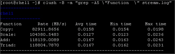
rhel1
-----------------------------------------------------------------------------------
Function Rate (MB/s) Avg time Min time Max time
Copy: 82911.8656 0.0158 0.0154 0.0198
Scale: 104380.5483 0.0127 0.0123 0.0236
Add: 118139.0089 0.0167 0.0163 0.0243
Triad: 118804.7870 0.0167 0.0162 0.0231
![]() Note: Results can vary based on the configuration.
Note: Results can vary based on the configuration.
Running MapR RPCtest
MapR RPCtest is network bandwidth measurement test. In this solution the methodology adopted to verify the network bandwidth across the cluster requires configuring half the nodes as senders and remaining half as receivers. This test is included in MapR software available at /opt/mapr/th/tools/rpctest as part of the installation.
To run the RPCtest, complete the following steps:
1. Log on to the admin node and run the following commands to create the script:
#!/bin/bash
# Define sender nodes
# 8 servers in each rack act as servers and the other half as clients
senders=( 10.4.1.31 10.4.1.33 10.4.1.35 10.4.1.37
10.4.1.39 10.4.1.41 10.4.1.43 10.4.1.45
10.4.1.47 10.4.1.49 10.4.1.51 10.4.1.53
10.4.1.55 10.4.1.57 10.4.1.59 10.4.1.61
10.4.1.63 10.4.1.65 10.4.1.67 10.4.1.69
10.4.1.71 10.4.1.73 10.4.1.75 10.4.1.77
10.4.1.79 10.4.1.81 10.4.1.83 10.4.1.85
10.4.1.87 10.4.1.89 10.4.1.91 10.4.1.93 )
for node in "${half1[@]}"; do
ssh -n $node /opt/mapr/servers/tools/rpctest -server &
done
sleep 9 # let the servers set up
# Define receiver nodes
receivers=( 10.4.1.32 10.4.1.34 10.4.1.36 10.4.1.38
10.4.1.40 10.4.1.42 10.4.1.44 10.4.1.46
10.4.1.48 10.4.1.50 10.4.1.52 10.4.1.54
10.4.1.56 10.4.1.58 10.4.1.60 10.4.1.62
10.4.1.64 10.4.1.66 10.4.1.68 10.4.1.70
10.4.1.72 10.4.1.74 10.4.1.76 10.4.1.78
10.4.1.80 10.4.1.82 10.4.1.84 10.4.1.86
10.4.1.88 10.4.1.90 10.4.1.92 10.4.1.94 )
i=0
for node in "${receivers[@]}"; do
ssh -n $node "/opt/mapr/servers/tools/rpctest -client 5000 \ ${senders[$i]} > rpctest.log" &
((i++))
done
#wait $! # Comment/uncomment this to make it sequential/concurrent
sleep 5
tmp=${half1[@]}
clush -w ${tmp// /,} pkill rpctest
2. Run the runRPCtest.sh command from the admin node.
![]()
3. Results are generated on receiver nodes. Verify results for all the nodes.
$clush -B -w 10.4.1.[19-26, 35-42, 51-58,67-74] cat rpctest.log
---------------
Rhel19
---------------
23:49:42 rpcs 17620, mb 1150.6
23:49:43 rpcs 17772, mb 1164.7
23:49:44 rpcs 17771, mb 1164.6
23:49:45 rpcs 17024, mb 1115.7
Rate: 1108.93 mb/s, time: 4.73158 sec, #rpcs 80063, rpcs/sec 16921
---------------
Running IOzone Benchmark
IOzone is a filesystem benchmark that measures the performance of various I/O operations, such as read, write, re-read, re-write, fread, fwrite, random read and random write.
![]() Warning:
Warning: ![]() IOzone is data destructive. Do not run the test on disks with data.
IOzone is data destructive. Do not run the test on disks with data.
To run the IOzone benchmark test, complete the following steps:
1. Download IOzone from http://www.iozone.org/ and copy to all nodes at /root/.
2. Create the following script, run IOzone.sh on the admin node.
#!/bin/bash
# Parallel IOzone tests to stress/measure disk controller
# These tests are destructive therefore
# Test must be run BEFORE MapR filesystem is formatted with disksetup
# Run iozone command once on a single device to verify iozone command
D=$(dirname "$0")
abspath=$(cd "$D" 2>/dev/null && pwd || echo "$D")
# run iozone with -h option for usage, adjust path below for iozone location
# Set list of device names for the 'for' loop
lsblk -id | grep -o ^sd. | sort > /tmp/iozone.disks
for i in `lsblk -i | grep -B2 md[0-1] | grep -v '-' | awk '{print $1}'`; do sed -i "/$i/d" /tmp/iozone.disks; done
disks=`cat /tmp/iozone.disks | xargs`
echo $disks
set -x
for disk in $disks; do
echo $abspath/iozone -I -r 1M -s 80G -i 0 -i 1 -i 2 -f /dev/$disk > $disk-iozone.log&
sleep 3 #Some controllers seem to lockup without a sleep
done
3. Copy runIOzone.sh to all the nodes at location /root/.
4. Run the following command to start the test:
clush -B -a runIOzone.sh
5. Verify that the tests are running and wait for its completion.
clush -B -a "ps -aef | grep iozone | wc -l"
---------------
rhel[1-64] (64)
---------------
6. Run the following command to verify the test results.
The test result is generated for each disk as sd<x>-iozone.log, where <x> is the device id. These logs have sequential and random write and read latencies from each disks.
$ grep " 83886080 " sd*.log
sdb-iozone.log: 83886080 1024 97978 97951 100673 99254 49002 66552
sdc-iozone.log: 83886080 1024 101290 100745 97803 97006 48863 66671
sdd-iozone.log: 83886080 1024 94286 94937 96752 95872 48871 65605
![]() Note
Note ![]() Results can vary based on configuration.
Results can vary based on configuration.
Installing MapR
Installing MapR software across the cluster involves performing several steps on each node. To make the installation process simpler, start with the installation of core MapR components such as CLDB, MapR-FS, NFS gateway and Yarn. Any additional Hadoop ecosystem components can be easily installed by following instructions on http://doc.mapr.com/display/MapR/Ecosystem+Guide. This section will follow Table 8 role assignments for installation of services on the 64-node cluster.
The following sections describe the steps and options for installing MapR software:
· Preparing Packages and Repositories
· MapR Installation
· Installing MapR packages
· Verify successful installation
· Configure the Node with the configure.sh Script
· Formatting Disks with the disksetup Script
Planning the Cluster
The first step towards deploying the MapR is planning which nodes contribute to the cluster, and selecting the services that will run on each node.
MapR Services
In a typical cluster, most nodes are dedicated to data processing and storage, and a smaller number of nodes run services that provide cluster coordination and management. Some applications run on cluster nodes and others run on client nodes that can communicate with the cluster.
The following table shows some of the services that can be run on a node.
Table 7 below shows some of the MapR services and corresponding descriptions.
| MapReduce |
Storage |
Management |
Application |
|
| Service |
Description |
|||
| Warden |
Warden runs on every node, coordinating the node's contribution to the cluster. |
|||
| NodeManager |
Hadoop YARN NodeManager service. The NodeManager manages node resources and monitors the health of the node. It works with the ResourceManager to manage YARN containers that run on the node. |
|||
| FileServer |
FileServer is the MapR service that manages disk storage for MapR-FS and MapR-DB on each node. |
|||
| CLDB |
Maintains the container location database (CLDB) service. The CLDB service coordinates data storage services among MapR-FS FileServer nodes, MapR NFS gateways, and MapR clients. |
|||
| NFS |
Provides read-write MapR Direct Access NFS access to the cluster, with full support for concurrent read and write access. |
|||
| MapR HBase Client (optional) |
Provides access to MapR-DB tables via HBase APIs. Required on all client nodes that will access table data in MapR-FS |
|||
| ResourceManager |
Hadoop YARN ResourceManager service. The ResourceManager manages cluster resources, and tracks resource usage and node health. |
|||
| ZooKeeper |
Enables high availability (HA) and fault tolerance for MapR clusters by providing coordination. |
|||
| HistoryServer |
Archives MapReduce job metrics and metadata. |
|||
| Web Server |
Runs the MapR Control System. |
|||
| Pig |
Pig is a high-level data-flow language and execution framework. |
|||
| Hive |
Hive is a data warehouse that supports SQL-like ad hoc querying and data summarization. |
|||
| Flume |
Flume is a service for aggregating large amounts of log data |
|||
| Oozie |
Oozie is a workflow scheduler system for managing Hadoop jobs. |
|||
| Mahout |
Mahout is a set of scalable machine-learning libraries that analyze user behavior. |
|||
| Spark |
Spark is an processing engine for large datasets., you can set it up as standalone or managed by Yarn. In this CVD, we have Yarn manage spark |
|||
| Sqoop |
Sqoop is a tool for transferring bulk data between Hadoop and relational databases. |
|||
Node Types
The MapR installer categorizes nodes as control nodes (which runs only cluster management services to manage the cluster), data nodes, control-as-data nodes (which combine the functions of control and data nodes), or client nodes. For deployment of MapR on Cisco UCS Integrated Infrastructure for Big Data, control services co-exist on data nodes (control-as-data node) as control services have a small footprint. Client node could be any node accessing the MapR cluster (all nodes in the MapR cluster are also client nodes).
Table 8 shows the Node Types and their descriptions
| Node Type |
Description |
| Data node |
Used for processing data, they have FileServer and TaskTracker services installed. |
| Control-as-data node |
Acts as both control and data nodes. They perform both functions and have both sets of services installed. |
| Client node |
Provides access to the cluster so the user can communicate via the command line or the MapR Control System. Client nodes provide access to each node on the cluster so the user can submit jobs and retrieve data. A client node can be an edge node of the cluster, laptop, or any Windows machine. |
Hostnames and Roles
This section describes the cluster plan of a 64-node cluster with hostnames and roles assignments for the following services as shown in below.
· ResourceManager (RM)
· HistoryServer (HS)
· NodeManager (NM)
· TaskTracker (TT, optional)
· JobTracker (JT, optional), FileServer (FS)
· Container Location Database (CLDB)
· Zookeeper,
· Webserver
![]() Note: Starting with MapR version 4.0, both Yarn and MapReduce V1 are supported not only in the same cluster but also on the same node.
Note: Starting with MapR version 4.0, both Yarn and MapReduce V1 are supported not only in the same cluster but also on the same node.
Table 9 Lists Host Names and Role Assignments.
Table 9 Lists Host Names and Role Assignments
| Rack-1 Hostnames |
MapR Roles |
Rack-2 Hostnames |
MapR Roles |
Rack-3 Hostnames |
MapR Roles |
Rack-4 Hostnames |
MapR Roles
|
| rhel1 |
CLDB,FS, NM, NFS,HS, Spark-history-server |
rhel17 |
CLDB, FS, NM, NFS, HS |
rhel33 |
CLDB, FS, NM, NFS,HS |
rhel49 |
FS, NM, NFS |
| rhel2 |
ZooKeeper |
rhel18 |
ZooKeeper |
rhel34 |
ZooKeeper |
rhel50 |
FS, NM, NFS |
| FS, NM, NFS |
FS, NM, NFS |
FS, NM, NFS |
|||||
| rhel3 |
Webserver,
|
rhel19 |
Webserver, |
rhel35 |
Webserver, |
rhel51 |
Webserver, |
| FS, NM, NFS |
FS, NM, NFS |
FS, NM, NFS |
FS, NM, NFS |
||||
| rhel4 |
FS, NM, NFS, |
rhel20 |
FS, NM, NFS, |
rhel36 |
FS, NM, NFS |
rhel52 |
FS, NM, NFS |
| rhel5 |
FS, NM, NFS, RM |
rhel21 |
FS, NM, NFS, RM |
rhel37 |
FS, NM, NFS, RM |
rhel53 |
FS, NM, NFS |
| rhel6 |
FS, NM, NFS |
rhel22 |
FS, NM, NFS |
rhel38 |
FS, NM, NFS |
rhel54 |
FS, NM, NFS |
| rhel7 |
FS, NM, NFS |
rhel23 |
FS, NM, NFS |
rhel39 |
FS, NM, NFS |
rhel55 |
FS, NM, NFS |
| rhel8 |
FS, NM, NFS |
rhel24 |
FS, NM, NFS |
rhel40 |
FS, NM, NFS |
rhel56 |
FS, NM, NFS |
| rhel9 |
FS, NM, NFS |
rhel25 |
FS, NM, NFS |
rhel41 |
FS, NM, NFS |
rhel57 |
FS, NM, NFS |
| rhel10 |
FS, NM, NFS |
rhel26 |
FS, NM, NFS |
rhel42 |
FS, NM, NFS |
rhel58 |
FS, NM, NFS |
| rhel11 |
FS, NM, NFS |
rhel27 |
FS, NM, NFS |
rhel43 |
FS, NM, NFS |
rhel59 |
FS, NM, NFS |
| rhel12 |
FS, NM, NFS |
rhel28 |
FS, NM, NFS |
rhel44 |
FS, NM, NFS |
rhel60 |
FS, NM, NFS |
| rhel13 |
FS, NM, NFS |
rhel29 |
FS, NM, NFS |
rhel45 |
FS, NM, NFS |
rhel61 |
FS, NM, NFS |
| rhel14 |
FS, NM, NFS |
rhel30 |
FS, NM, NFS |
rhel46 |
FS, NM, NFS |
rhel62 |
FS, NM, NFS |
| rhel15 |
FS, NM, NFS |
rhel31 |
FS, NM, NFS |
rhel47 |
FS, NM, NFS |
rhel63 |
FS, NM, NFS |
| rhel16 |
FS, NM, NFS |
rhel32 |
FS, NM, NFS |
rhel48 |
FS, NM, NFS |
rhel64 |
FS, NM, NFS |
![]() Note: All Job management are performed by Resource Manager and Node Manager. In this CVD, Task Tracker and Job Tracker are not installed.
Note: All Job management are performed by Resource Manager and Node Manager. In this CVD, Task Tracker and Job Tracker are not installed.
Preparing Packages and Repositories
A local repository on the admin node is set up to provide access to installation packages. With this method, the package manager on each node retrieves the installations package from the admin node (rhel1 is used as admin node as already mentioned) and installs the packages. Nodes do not need to have an internet access.
Below are instructions on setting up a local repository for Red Hat Linux distribution. These instructions create a single repository that includes both MapR components and the Hadoop ecosystem components.
RPM Repositories for MapR Core Software
MapR hosts rpm repositories for installing the MapR core software using Linux package management tools. For every release of the core MapR software, a repository is created for each supported platform.
These platform-specific repositories are hosted at:
http://package.mapr.com/releases/<version>/<platform>
http://package.mapr.com/releases/v5.1.0/redhat/mapr-v5.1.0GA.rpm.tgz
http://archive.mapr.com/releases/ecosystem-all/redhat/mapr-ecosystem-5.x-20160729.rpm.tgz
RPM Repositories for Hadoop Ecosystem Tools
MapR hosts rpm repositories for installing Hadoop ecosystem tools, such as Spark, Flume, Hive, Mahout, Oozie, Pig and Sqoop. At any given time, MapR's recommended versions of ecosystem tools that work with the latest version of MapR core software are available in the link below.
These platform-specific repositories are hosted at: http://package.mapr.com/releases/ecosystem-5.x
To create the local repositories, follow the steps below:
1. Login as root on the admin node (rhel1).
2. Create the following directory on rhel1
mkdir -p /var/www/html/mapr.local
3. On a node that is connected to the Internet, download the following files, substituting the appropriate <version> and <datestamp>:
wget http://package.mapr.com/releases/v<version>/redhat/mapr-v<version>GA.rpm.tgz
wget http://package.mapr.com/releases/ecosystem/redhat/mapr-ecosystem-<datestamp>.rpm.tgz
![]() Note: For this document we use the version 5.1.0. See MapR Repositories and Package Archives for the correct paths for all past releases.at http://archive.mapr.com/releases/
Note: For this document we use the version 5.1.0. See MapR Repositories and Package Archives for the correct paths for all past releases.at http://archive.mapr.com/releases/
[root@LINUXJB ~]# wget http://package.mapr.com/releases/v5.1.0/redhat/mapr-v5.1.0GA.rpm.tgz
[root@LINUXJB ~]# wget http://archive.mapr.com/releases/ecosystem-all/redhat/mapr-ecosystem-5.x-20160729.rpm.tgz
![]() Note: The server internet-host is an edge host that has access to the internet and to the admin node (rhel1). It is not a part of the MapR cluster. It is used to just download and transfer files to the admin node from the internet as the admin node is not directly connected to the internet.
Note: The server internet-host is an edge host that has access to the internet and to the admin node (rhel1). It is not a part of the MapR cluster. It is used to just download and transfer files to the admin node from the internet as the admin node is not directly connected to the internet.
4. Copy the files to /var/www/html/mapr.local on the admin node, and extract them there.
[root@LINUXJB ~]# scp mapr-v5.1.0GA.rpm.tgz rhel1:/var/www/html/mapr.local/
[root@LINUXJB ~]# scp mapr-ecosystem-5.x-20160729.rpm.tgz rhel1:/var/www/html/mapr.local/
Connect to the admin (rhel1) node.
[root@rhel1 mapr.local]# tar -xvzf mapr-v5.1.0GA.rpm.tgz
[root@rhel1 mapr.local]# tar -xvzf mapr-ecosystem-5.x-20160729.rpm.tgz
Create the base repository headers:
[root@rhel1 mapr.local]# createrepo /var/www/html/mapr.local
To add the repository on each node, complete the following steps:
1. Create repo file /etc/yum.repos.d/maprtech.repo on the admin node (rhel1):
vi /etc/yum.repos.d/maprtech.repo
[maprtech]
name=MapR Technologies, Inc.
baseurl=http://10.4.1.31/mapr.local
enabled=1
gpgcheck=0
2. Copy the maprtech.repo specification to all the nodes of the cluster. Then, update the yum metadata cache so that the repository files will be properly accessed.
clush –a -c /etc/yum.repos.d/maprtech.repo
clush -a yum makecache
![]()
3. Create mapr user across all nodes
Users of the cluster must have the same credentials and user id on every node in the cluster. Each user (or department) that runs the MapR jobs needs an account and must belong to a common group (gid). If a directory service, such as LDAP, is not used, this user is created on each node. Every user must have the same uid and primary gid on every node.
In addition, a MapR user with full privileges to administer the cluster is created. If a user named 'mapr' does not exist. It is recommended that the user named 'mapr' is created in advance in order to test the connectivity issues prior to the installation step.
clush -a groupadd -g 5000 mapr
clush -a "useradd -g 5000 -u 5000 mapr"
clush -a -B "echo maprpassw0rd | passwd mapr --stdin"
![]()
![]() Note: Password of mapr user is set to maprpassw0rd
Note: Password of mapr user is set to maprpassw0rd
4. Verify mapr user on all nodes
clush -a -B id mapr
![]()
MapR Software Installation
Perform the following steps on each node:
1. Install the planned MapR services as shown in Table 10.
2. Run the configure.sh script to configure the node.
3. Format raw drives and partitions allocated to MapR using the disksetup script.
Table 10 MapR Services and Packages
| Service |
Package |
| MapR core |
mapr-core |
| Cluster location DB (CLDB) |
mapr-cldb |
| History server |
mapr-historyserver |
| ResourceManager and/or JobTracker |
mapr-resourcemanager and/or mapr-jobtracker |
| MapR Control System |
mapr-webserver |
| MapR File Server |
mapr-fileserver |
| NFS |
mapr-nfs |
| NodeManager and/or TaskTracker |
mapr-nodemanager and/or mapr-tasktracker |
| ZooKeeper |
mapr-zookeeper |
| Hadoop Ecosystem Components |
Package |
| Drill |
mapr-drill |
| Spark |
mapr-spark |
| Hive |
mapr-hive |
| Mahout |
mapr-mahout |
| Oozie |
mapr-oozie |
| Pig |
mapr-pig |
| Sqoop |
mapr-sqoop |
Installing MapR packages
Use the commands in this section to install the appropriate packages for each node, based on the Cluster Plan, as shown in Table 10 above. Configuring the local yum repository ensures that the package dependencies will be managed correctly.
1. Install CLDB using the following command:
clush -B -w rhel[1,17,33] 'yum -y install mapr-cldb’
2. Install ResourceManager:
clush -B -w rhel[5,21,37] 'yum -y install mapr-resourcemanager'
3. Install Mapr Webserver:
clush -B -w rhel[3,19,35,51] 'yum -y install mapr-webserver'
![]() Note: Make sure httpd is not installed on these nodes.
Note: Make sure httpd is not installed on these nodes.
4. Install Mapr-Zookeeper:
clush -B -w rhel[2,18,34] 'yum -y install mapr-zookeeper'
5. Install Mapr-historyserver:
clush -B -w rhel[1,17,33] 'yum -y install mapr-historyserver'
6. Install NFS, Fileserver and Nodemanager on all cluster nodes:
clush -B -a 'yum -y install mapr-fileserver mapr-nfs mapr-nodemanager'
7. Configuring MapR nfs gateway service
Run the following commands from the admin node (rhel1)
clush -a mkdir -p /mapr
echo "localhost:/mapr /mapr hard,nolock" > /opt/mapr/conf/mapr_fstab
clush -a -c /opt/mapr/conf/mapr_fstab --dest /opt/mapr/conf/mapr_fstab
![]()
Verification of Installation
To verify that the software has been installed successfully, check the /opt/mapr/roles directory on each node. The software is installed in directory /opt/mapr and a file is created in /opt/mapr/roles for every service that installs successfully. Examine this directory to verify installation for the node. For example:
# clush –a –B “ls -l /opt/mapr/roles”
1. Configure the Node with the configure.sh Script
2. The script configure.sh configures a node to be part of a MapR cluster, or modifies services running on an existing node in the cluster. The script creates (or updates) configuration files related to the cluster and the services running on the node. Before performing this step, make sure to have a list of the hostnames of the CLDB and ZooKeeper nodes, Optionally specify the ports for the CLDB and ZooKeeper nodes as well. If not specified, the default ports are assigned as:
- CLDB – 7222
- ZooKeeper – 5181
The script configure.sh takes an optional cluster name and log file, and comma-separated lists of CLDB and ZooKeeper host names or IP addresses (and optionally ports), using the following syntax:
/opt/mapr/server/configure.sh -C <host>[:<port>][,<host>[:<port>]...] -Z <host>[:<port>][,<host>[:<port>]...] [-L <logfile>][-N <cluster name>]
3. Configure nodes with CLDB, Zookeeper and History server Services
clush -B -a '/opt/mapr/server/configure.sh -C rhel1,rhel17,rhe33 -Z rhel2,rhel18,rhel34 –HS rhel1,rhel17,rhel33 -N ciscomapr -no-autostart'
Formatting Disks with the disksetup Script
mapr-fileserver is installed on all the nodes, use the following procedure to format disks and partitions to be used by MapR-FS.
The disksetup script is used to format disks to be used by the MapR cluster. The following script creates a text file /tmp/MapR.disks listing the disks and partitions to be used by MapR on the node. Each line lists a single disk.
Identify and Format the Data Disks for MapR
1. Create a list of disks to be formatted. (delete earlier instance of this file)
2. Create the following script on rhel1 and copy it to all the nodes
vi mapr_disks.sh
#!/bin/bash
#This script creates files (MapR.disks) containing a list of non OS disk drives used during MapR Installation.
[[ "-x" == "${1}" ]] && set -x && set -v && shift 1
count=1
for HD in /sys/class/scsi_host/host?/scan
do
echo '- - -' > ${HD}
done
for HD in /dev/sd?
do
if [[ -b ${HD} && `/sbin/parted -s ${HD} print quit|/bin/grep -c boot` -ne 0
]]
then
continue
else
echo $HD >> /tmp/MapR.disks
fi
done
3. Change the permission and copy mapr_disks.sh to all the nodes
chmod +x mapr_disks.sh
clush –a –c mapr_disks.sh
4. Run the mapr_disks.sh script on all the nodes.
clush –a -B /root/mapr_disks.sh
5. Verify the file on all nodes does not contain os drives
clush –aB cat /tmp/MapR.disks
6. Confirm that the disks are not in use. The cfdisk, mount, and pvdisplay utilities can be used to confirm that the system is not using the disks listed in /tmp/MapR.disks. This confirmation is not necessary during the initial setup, but may be relevant when nodes are removed or re-added to the cluster.
7. Format the disks to MapR-FS
clush -B -a “/opt/mapr/server/disksetup –F –W 5 /tmp/MapR.disks”
![]() The script disksetup removes all data from the specified disks. Make sure to specify the disks correctly, and that all data has been backed up elsewhere.
The script disksetup removes all data from the specified disks. Make sure to specify the disks correctly, and that all data has been backed up elsewhere.
This procedure assumes free, unmounted physical partitions or hard disks for use by MapR.
Update Environment Variables in /opt/mapr/conf/env.sh
There are a few key environment variables for the MapR software saved in /opt/mapr/conf/env.sh. These values must be properly configured BEFORE launching the cluster software. The default file is shown below:
#!/bin/bash
# Copyright (c) 2009 & onwards. MapR Tech, Inc., All rights reserved
# Please set all environment variable you want to be used during MapR cluster
# runtime here.
# namely MAPR_HOME, JAVA_HOME, MAPR_SUBNETS
#export JAVA_HOME=
#export MAPR_SUBNETS=
#export MAPR_HOME=
#export MAPR_ULIMIT_U=
#export MAPR_ULIMIT_N=
#export MAPR_SYSCTL_SOMAXCONN=
8. For this deployment, explicitly set the values for JAVA_HOME and MAPR_SUBNETS as shown below. Edit the /opt/mapr/conf/env.sh file with the following environment variables as shown below:
export JAVA_HOME=/usr/java/jdk1.8.0_91/
export MAPR_SUBNETS=10.4.1.0/24,10.5.1.0/24
![]() Note: By mentioning MAPR_SUBNETS and providing the two vlans, this enables MapR to use both VLANs (NICs) for traffic and thus using full 20 GiGE for Hadoop traffic.
Note: By mentioning MAPR_SUBNETS and providing the two vlans, this enables MapR to use both VLANs (NICs) for traffic and thus using full 20 GiGE for Hadoop traffic.
9. Make those changes in rhel1:/opt/mapr/conf/env.sh and then distribute them to the entire cluster with the command
$ clush –B –a –c /opt/mapr/conf/env.sh
Bringing Up the Cluster
The installation of software across a cluster of nodes will go more smoothly if the services have been pre-planned and each node has been validated. Referring to the cluster design developed in section “Planning the Cluster”, ensure that each node has been prepared and that the MapR packages have been installed on each node in accordance with the plan. The process for launching the cluster can be broken down into several steps:
· Initialization Sequence
· Troubleshooting
· Installing the Cluster License
· Verifying Cluster Status
The initialization sequence involves starting the ZooKeeper service, starting the CLDB service, setting up the administrative user, and installing a MapR license. Once these initial steps are done, the cluster is functional on a limited set of nodes. Not all services are started yet, but the MapR Control System Dashboard, or the MapR Command Line Interface are available, to examine nodes and activity on the cluster.
Initialization Sequence
First, start the ZooKeeper service. It is important that all ZooKeeper instances start up, because the rest of the system cannot start unless a majority of ZooKeeper instances are up and running. Next, start the warden service on each node, or at least on the nodes that host the CLDB and webserver services. The warden service manages all MapR services on the node (except ZooKeeper) and helps coordinate communications. Starting the warden automatically starts the CLDB.
To bring up the cluster, complete the following steps:
1. Start ZooKeeper on all nodes where it is installed, by issuing one of the following commands:
clush -B -w rhel[2,18,34] service mapr-zookeeper start
![]()
2. Verify that the ZooKeeper service is running properly :
clush –B –w rhel[2,18,34] service mapr-zookeeper status
![]()
The servers should display the running pid for the zookeeper process
3. On the nodes running CLDB or webserver, start the warden by issuing one of the following commands
clush -a service mapr-warden start
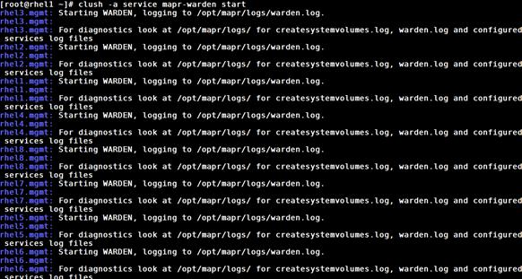
![]() Note: Before continuing, wait 30 to 60 seconds for the warden to start the CLDB service. Calls to MapR (such as maprcli) may fail if executed before the CLDB has started successfully.
Note: Before continuing, wait 30 to 60 seconds for the warden to start the CLDB service. Calls to MapR (such as maprcli) may fail if executed before the CLDB has started successfully.
4. Log in to rhel1 and issue the following command to give full permission to the chosen administrative user mapr:
/opt/mapr/bin/maprcli acl edit -type cluster -user mapr:fc
Note: fc is full control.
5. Confirm that the MapR-FS is up by running the following command,
hadoop fs -ls /
Installing Spark
This CVD describes the installation process of Spark on Yarn.
1. Log in to rhel1 (admin node) and install the MapR-Spark package on all the nodes using the clush command.
clush -a yum -y install mapr-spark
![]()
2. Install the spark-history-server package on rhel1 server.
yum -y install mapr-spark-historyserver
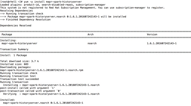
3. Create the /apps/spark directory on MapR-FS and set the correct permissions on the directory as follows from the rhel1,
hadoop fs -mkdir /apps/spark
hadoop fs -chmod 777 /apps/spark
![]()
4. Edit the container-executer.cfg as shown below to allow user root to execute jobs only for testing purposes. Restore the default value once the testing is completed.
cd /opt/mapr/hadoop/hadoop-2.7.0/etc/hadoop
![]()
vi container-executor.cfg
![]()
min.user.id=0
allower.system.users=mapr,root
5. Copy the container-executor.cfg file on all the nodes
clush -a -b -c /opt/mapr/hadoop/hadoop-2.7.0/etc/hadoop/container-executor.cfg
![]()
6. Run the spark shell command to enter interactive mode for spark.
cd /opt/mapr/spark/spark-1.6.1/
[root@rhel1 spark-1.6.1]# ./bin/spark-shell –-master yarn-client
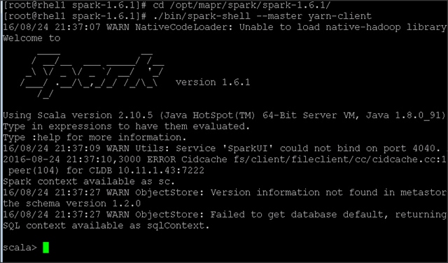
7. Confirm the installation of spark-historyserver using following URL
http://rhel1:18080
MapR streams
MapR streams is a module in MapR core. The following section describes how to enable MapR license including streams.
Installing the Cluster License
![]() Note: Contact MapR sales representative to obtain a valid MapR license key. This is necessary to enable the enterprise-class features of the MapR packages (e.g., MapR-DB, NFS, ResourceManager HA, storage snapshots and mirrors, etc.).
Note: Contact MapR sales representative to obtain a valid MapR license key. This is necessary to enable the enterprise-class features of the MapR packages (e.g., MapR-DB, NFS, ResourceManager HA, storage snapshots and mirrors, etc.).
Using Web-based MCS to Install the License
1. On a machine that is connected to the cluster and to the Internet, perform the following steps to open the MapR Control System and install the license:
2. In a browser, view the MapR Control System by navigating to the node that is running the MapR Control System. For Example rhel3.
https://<MCS node>:8443
![]() Note: The node won't have an HTTPS certificate yet, so the browser will warn that the connection is not trustworthy. Ignore the warning this time.
Note: The node won't have an HTTPS certificate yet, so the browser will warn that the connection is not trustworthy. Ignore the warning this time.
3. The first time MapR starts, accept the Terms of Use and choose whether to enable the MapR Dial Home service.
4. Log in to the MapR Control System as the administrative user. Until a license is applied, the MapR Control System dashboard might show some nodes in the amber "degraded" state.
![]() Note: The nodes health will be in amber until the license is applied. Once the license is applied, the node health should come up as green.
Note: The nodes health will be in amber until the license is applied. Once the license is applied, the node health should come up as green.
Figure 58 MapR Control System
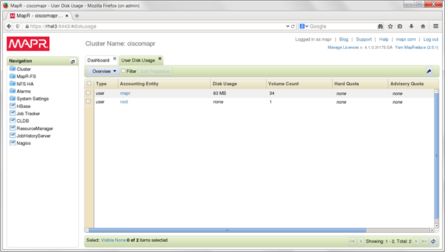
5. In the navigation pane of the MapR Control System, expand the System Settings Views group and click Manage Licenses to display the MapR License Management dialog (Figure 59).
6. Click Add Licenses via copy/paste and paste the license key.
7. If the cluster is already registered, the license is applied automatically. Otherwise, click OK to register the cluster on MapR.com and follow the instructions there.

Installing a License from the Command Line (optional)
Use the following steps if the cluster and the Internet are not accessible at the same time.
1. Obtain a valid license file from MapR
2. Copy the license file to a cluster node
3. Run the following command to add the license:
maprcli license add [ -cluster <name> ] -license <filename> -is_file true
Restarting MapR Services after License Installation
Certain HA features of the MapR cluster will not start properly until a valid license is installed. Once the trial license or a permanent one provided by mapr is successfully installed, restart the distributed CLDB services, as well as the ResourceManager service and the NFS service. This can be done from any node in the cluster with the following commands:
maprcli node services –name cldb –action start –filter “[csvc==cldb]”
maprcli node services –name resourcemanager –action start –filter “[csvc==resourcemanager]”
maprcli node services –name nfs –action start –filter “[csvc==nfs]”
![]()
The effect of those commands is to start the respective services on all nodes in the cluster configured with those services. Nodes on which the service is already running will not be affected.
Verifying Cluster Status
Verify Cluster Status using the Web Interface
1. Log in to the MapR Control System.
2. Under the Cluster group in the left pane, click Dashboard.
3. Check the Services pane and make sure each service is running the correct number of instances, according to the cluster plan.
Verifying Cluster Status Using the Command Line Interface
1. Log in to a cluster node
2. Use the following command to list MapR services:
$ maprcli service list
$ maprcli license list
$ maprcli disk list -host <name or IP address>
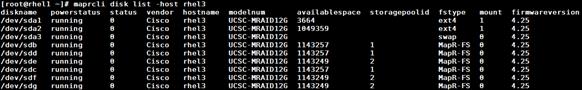
Enabling MapR Streams
Apply the license in the MCS to enable MapR streams.
1. Confirm the MapR streams modules licence are installed.
![]()

Installing Additional Hadoop Components
The final step in installing a MapR cluster is to install and bring up Hadoop ecosystem components such as the following and integrating them with a MapR cluster:
Please refer to the MapR Install guide at http://doc.mapr.com/display/MapR/Ecosystem+Guide for detailed instructions on installation and configuration of desired Hadoop components.
· Apache Drill - Installing and using Drill on a MapR cluster
· Flume- Installing and using Flume on a MapR cluster
· Hive- Installing and using Hive on a MapR cluster, and setting up a MySQL metastore
· Hue - Installing and using Hue on MapR
· Mahout- Environment variable settings needed to run Mahout on MapR
· Oozie- Installing and using Oozie on a MapR cluster
· Pig- Installing and using Pig on a MapR cluster
· Spark- Installing and running Spark on MapR
· Sqoop- Installing and using Sqoop on a MapR cluster
Troubleshooting
Difficulty bringing up the cluster can be daunting, but most cluster problems are easily resolved. For the latest support tips, visit http://answers.mapr.com.
Can each node connect with the others? For a list of ports that must be open, see http://answers.mapr.com.
Is the warden running on each node? On the node, run the following command as root:
$ service mapr-warden status
WARDEN running as process 18732
If the warden service is not running, check the warden log file, /opt/mapr/logs/warden.log, for clues.
To restart the warden service run:
$ service mapr-warden start
The ZooKeeper service is not running on one or more nodes.
· Check the warden log file for errors related to resources, such as low memory
· Check the warden log file for errors related to user permissions
· Check for DNS and other connectivity issues between ZooKeeper nodes
The MapR CLI program /opt/mapr/bin/maprcli won't run.
· Did you configure this node? See Installing MapR Software.
· Permission errors appear in the log
Check that MapR's changes to the following files have not been overwritten by automated configuration management tools:
| /etc/sudoers |
Allows the mapr user to invoke commands as root |
| /etc/security/limits.conf |
Allows MapR services to increase limits on resources such as memory, file handles, threads and processes, and maximum priority level |
| /etc/udev/rules.d/99-mapr-disk.rules |
Covers permissions and ownership of raw disk devices |
Before contacting Support, collect cluster's logs using the mapr-support-collect script.
Conclusion
The MapR Converged Data Platform allows enterprises to build reliable, real-time applications by providing: a single cluster for streams, file storage database and analytics, persistence of streaming data, providing direct access to batch and interactive frameworks, a unified security framework for data-in-motion and data-at-rest with authentication, authorization and encryption, and a utility-grade reliability with self-healing and no single point-of-failure architecture.
The Cisco UCS® Integrated Infrastructure for Big Data and Analytics with MapR Converged Data Platform enables the next-generation of big data architecture by providing simplified and centralized management, industry-leading performance, and a linearly scaling infrastructure and software platform.
The configuration detailed in the document can be extended to clusters of various sizes depending on application demands. Up to 80 servers (5 racks) can be supported with no additional switching in a single Cisco UCS domain with no network over-subscription. Scaling beyond 5 racks (80 servers) can be implemented by interconnecting multiple Cisco UCS domains using Nexus 9000 Series switches, scalable to thousands of servers and to hundreds of petabytes of storage, and managed from a single pane using Cisco UCS Central.
This section provides the BOM for the 64 nodes Performance Optimized Cluster. See Table 11 for BOM for the master rack, Table 12 for BOM for expansion racks (racks 2 to 4), Table 13 and Table 14 for software components.
![]() Note: If UCSD-SL-CPA4-P2 is added to the BOM all the required components for 16 servers only are automatically added. If not customers can pick each of the individual components that are specified after this and build the BOM manually.
Note: If UCSD-SL-CPA4-P2 is added to the BOM all the required components for 16 servers only are automatically added. If not customers can pick each of the individual components that are specified after this and build the BOM manually.
Table 11 Bill of Materials for C240M4SX Base Rack
![]() Note: If using the FI 6332 please refer to Table 1 for the SKU information.
Note: If using the FI 6332 please refer to Table 1 for the SKU information.
Table 12 Bill of Materials for Expansion Racks
Table 13 Red Hat Enterprise Linux License
| Red Hat Enterprise Linux |
||
| RHEL-2S2V-3A |
Red Hat Enterprise Linux |
64 |
| CON-ISV1-EL2S2V3A |
3 year Support for Red Hat Enterprise Linux |
64 |
Table 14 MapR Software Subscription License SKUs
| MapR Software Subscription Licenses |
||||
| UCS-BD-MPRMCD-B= |
UCS-BD-MCD-B-3Y |
MCD-B-36 |
Base LIC MapR Conv. Ent. MapR-DB 3 Yr. |
Base Subscription License for MapR Converged Enterprise Edition, includes base MapR-DB module. Includes Updates and Support. 3 Year Term. Price is Per Node. |
| UCS-BD-MPRMCH-B= |
UCS-BD-MCH-B-3Y |
MCH-B-36 |
Base LIC MapR Conv. Ent. Hadoop- 3 Yr. |
Base Subscription License for MapR Converged Enterprise Edition, includes base Hadoop module. Includes Updates and Support. 3 Year Term. Price is Per Node. |
| UCS-BD-MPRMCS-B= |
UCS-BD-MCS-B-3Y |
MCS-B-36 |
Base LIC MapR Conv. Ent., MapR Streams-3 Yr. |
Base Subscription License for MapR Converged Enterprise Edition, includes base MapR Streams module. Includes Updates and Support. 3 Year Term. Price is Per Node. |
| UCS-BD-MPRAS-SL= |
UCS-BD-AS-SL-3Y |
AS-SL-36 |
Apache Spark, a fast and general engine large-scale data processing-3 Yr. |
24/7 support for Apache Spark, a fast and general engine for large-scale data processing; Spark Core Engine, Shark, MLLib, Streaming and GraphX. Per Node Price for a 36-Month period. |
| UCS-BD-MPRHB-SL= |
UCS-BD-HB-SL-3Y |
HB-SL-36 |
Customer's use of Apache HBase-3 Yr. |
24/7 Support for Customer's use of Apache HBase. Per Node Price for a 36-Month period. |
| UCS-BD-MPRIQS-SL= |
UCS-BD-IQS-SL-3Y |
IQS-SL-36 |
Customer's use of Impala-3 Yr. |
24/7 Support for Customer's use of Impala - a low latency SQL query engine on Hadoop. Per Node Price for a 36-Month period. |
| UCS-BD-MPRSLR-SL= |
UCS-BD-SLR-SL-3Y |
SLR-SL-36 |
Apache SolR search option content on the MapR Cluster-3 Yr. |
Apache SolR search option for the content on the MapR Cluster. 3 Year Subscription |
Manan Trivedi is a Technical Marketing Engineer in the Data Center Solutions Group, Cisco Systems Inc. He is part of the solution engineering team focusing on big data infrastructure and performance.
James Sun, Senior Solutions Architect (MapR Technologies). James Sun manages the technological relationship with worldwide alliances at MapR Technologies. James has over 15 years of experience in information technology. Prior to MapR, he held several senior technical positions at technological companies such as NetApp, Yahoo and EMC. He holds a PhD. from Stanford University
Acknowledgements
· Jayanth Regula, Hadoop Admin in the Data Center Solutions Group at Cisco Systems
· Karthik Kulkarni, Big Data Solutions Architect, Data Center Solutions Group, Cisco Systems Inc.
· Barbara Dixon, Technical Writer, Data Center Solutions Group, Cisco Systems, Inc.
 Feedback