Cisco UCS Integrated Infrastructure for Big Data with IBM BigInsights for Apache Hadoop
Available Languages
Cisco UCS Integrated Infrastructure for Big Data with IBM BigInsights for Apache Hadoop
Building a 64 Node Hadoop Cluster
Last Updated: December 15, 2015

The CVD program consists of systems and solutions designed, tested, and documented to facilitate faster, more reliable, and more predictable customer deployments. For more information visit
http://www.cisco.com/go/designzone.
ALL DESIGNS, SPECIFICATIONS, STATEMENTS, INFORMATION, AND RECOMMENDATIONS (COLLECTIVELY, "DESIGNS") IN THIS MANUAL ARE PRESENTED "AS IS," WITH ALL FAULTS. CISCO AND ITS SUPPLIERS DISCLAIM ALL WARRANTIES, INCLUDING, WITHOUT LIMITATION, THE WARRANTY OF MERCHANTABILITY, FITNESS FOR A PARTICULAR PURPOSE AND NONINFRINGEMENT OR ARISING FROM A COURSE OF DEALING, USAGE, OR TRADE PRACTICE. IN NO EVENT SHALL CISCO OR ITS SUPPLIERS BE LIABLE FOR ANY INDIRECT, SPECIAL, CONSEQUENTIAL, OR INCIDENTAL DAMAGES, INCLUDING, WITHOUT LIMITATION, LOST PROFITS OR LOSS OR DAMAGE TO DATA ARISING OUT OF THE USE OR INABILITY TO USE THE DESIGNS, EVEN IF CISCO OR ITS SUPPLIERS HAVE BEEN ADVISED OF THE POSSIBILITY OF SUCH DAMAGES.
THE DESIGNS ARE SUBJECT TO CHANGE WITHOUT NOTICE. USERS ARE SOLELY RESPONSIBLE FOR THEIR APPLICATION OF THE DESIGNS. THE DESIGNS DO NOT CONSTITUTE THE TECHNICAL OR OTHER PROFESSIONAL ADVICE OF CISCO, ITS SUPPLIERS OR PARTNERS. USERS SHOULD CONSULT THEIR OWN TECHNICAL ADVISORS BEFORE IMPLEMENTING THE DESIGNS. RESULTS MAY VARY DEPENDING ON FACTORS NOT TESTED BY CISCO.
CCDE, CCENT, Cisco Eos, Cisco Lumin, Cisco Nexus, Cisco StadiumVision, Cisco TelePresence, Cisco WebEx, the Cisco logo, DCE, and Welcome to the Human Network are trademarks; Changing the Way We Work, Live, Play, and Learn and Cisco Store are service marks; and Access Registrar, Aironet, AsyncOS, Bringing the Meeting To You, Catalyst, CCDA, CCDP, CCIE, CCIP, CCNA, CCNP, CCSP, CCVP, Cisco, the Cisco Certified Internetwork Expert logo, Cisco IOS, Cisco Press, Cisco Systems, Cisco Systems Capital, the Cisco Systems logo, Cisco Unity, Collaboration Without Limitation, EtherFast, EtherSwitch, Event Center, Fast Step, Follow Me Browsing, FormShare, GigaDrive, HomeLink, Internet Quotient, IOS, iPhone, iQuick Study, IronPort, the IronPort logo, LightStream, Linksys, MediaTone, MeetingPlace, MeetingPlace Chime Sound, MGX, Networkers, Networking Academy, Network Registrar, PCNow, PIX, PowerPanels, ProConnect, ScriptShare, SenderBase, SMARTnet, Spectrum Expert, StackWise, The Fastest Way to Increase Your Internet Quotient, TransPath, WebEx, and the WebEx logo are registered trademarks of Cisco Systems, Inc. and/or its affiliates in the United States and certain other countries.
All other trademarks mentioned in this document or website are the property of their respective owners. The use of the word partner does not imply a partnership relationship between Cisco and any other company. (0809R)
© 2015 Cisco Systems, Inc. All rights reserved.
Table of Contents
Cisco UCS Integrated Infrastructure for Big Data
Cisco UCS 6200 Series Fabric Interconnects
Cisco UCS C-Series Rack Mount Servers
Cisco UCS Virtual Interface Cards (VICs)
IBM BigInsights for Apache Hadoop: A Complete Hadoop Platform
Port Configuration on Fabric Interconnects
Server Configuration and Cabling
Software Distributions and Versions
IBM BigInsights for Apache Hadoop
Red Hat Enterprise Linux (RHEL)
Deployment Hardware and Software
Performing Initial Setup of Cisco UCS 6296 Fabric Interconnects
Creating Pools for Service Profile Templates
Creating Policies for Service Profile Templates
Creating Local Disk Configuration Policy
Creating a Service Profile Template
Configuring Network Settings for the Template
Configuring Storage Policy for the Template
Configuring vNIC/vHBA Placement for the Template
Configuring the vMedia Policy for the Template
Configuring Server Boot Order for the Template
Configuring Server Assignment for the Template
Configuring Operational Policies for the Template
Configuring Disk Drives for the Operating System on Management Nodes
Installing Red Hat Enterprise Linux 6.5 on C220 M4 Systems
Installing Red Hat Enterprise Linux 6.5 using software RAID on Cisco UCS C240 M4 Systems
Setting Up Password-less Login
Configuring /etc/hosts on the Admin Node
Configure /etc/hosts Files on All Nodes
Creating Red Hat Enterprise Linux (RHEL) 6.5 Local Repo
Creating the Red Hat Repository Database
Upgrading Cisco Network Driver for VIC1227
Set TCP Retries and Port range
Disable Transparent Huge Pages
Configuring Data Drives on Master Nodes
Configuring Data Drives on Data Nodes
Configuring the Filesystem on all nodes
Installing IBM BigInsights for Apache Hadoop using the Graphical User Interface (GUI)
Download and Install BigInsights
Cisco and IBM Deliver Performance and Enterprise SQL on Hadoop for Businesses to Accelerate Data Science and Analytics
Cisco UCS Integrated Infrastructure for big data includes computing, storage, connectivity, and unified management capabilities to help companies manage the avalanche of data they must cope with today. It is built on Cisco UCS infrastructure using Cisco UCS 6200 Series Fabric Interconnects and Cisco UCS C-Series Rack Servers. This architecture is specifically designed for performance and linear scalability for big data workloads.
IBM BigInsights for Apache Hadoop offers great value to organizations that are dealing with Internet-scale volumes (petabytes) of data that exists in many different formats, which might be spread across many different locations; customers who are interested in greater flexibility for understanding patterns and doing efficient “what if” analyses against many different types and sources of data; and organizations that are interested in leveraging open source innovation for handling Internet-scale information.
Cisco UCS Integrated Infrastructure for Big Data with IBM BigInsights for Apache Hadoop offers these features and benefits:
· Provides advanced analytics built on Hadoop technology to meet big data analysis requirements.
· Designed for high performance and usability through performance-optimized capabilities, visualization, rich developer tools and powerful analytic functions.
· Delivers management, security and reliability features to support large-scale deployments and help speed up time to value.
· Integrates with IBM and other information solutions to help enhance data manipulation and management tasks.
Together, Cisco and IBM provide enterprises with transparent, simplified data as well as management integration with an enterprise application ecosystem. They are well positioned to help organizations exploit the valuable business insights in all their data, regardless of whether it's structured, semi structured or unstructured. IBM is the leading provider of enterprise-grade Hadoop infrastructure software and services along with a strong analytics stack. Cisco has been the leader in networking for decades, providing proven solutions that meet critical business requirements. Cisco UCS C-Series Rack-Mount Servers based on Intel Xeon processors complete these offerings, to provide a uniquely capable, industry-leading architectural platform for Hadoop-based applications.
Introduction
Some of the challenges facing data scientists and business analysts are to reuse their experience and learning in the tools they are already familiar with in the big data landscape.
Business analysts generally have extensive expertise in SQL, which has long been used for large-scale analytics. They want to leverage these existing SQL skills to find and visualize data across all sources, including Hadoop. A feature-rich SQL engine on Hadoop can immediately deliver analytic capabilities on Hadoop to a wide audience.
For data scientists, the challenge centers on data preparation and machine learning. Data scientists use these algorithms to build models for automated prediction, often using the open source R language to perform their work. However, as organizations turn to Hadoop to handle big data, they find that few machine learning implementations scale well across a Hadoop cluster. Data scientists need ways to leverage Hadoop for distributed analysis using familiar R functions.
Finally, IT administrators need to ensure the scalability, performance and security of Hadoop clusters without massive resource investments.
Cisco UCS Integrated Infrastructure for Big Data with IBM BigInsights for Apache Hadoop provides a unique solution addresses the concerns faced by data scientists, business analysts and IT administrators
IBM BigInsights for Apache Hadoop introduces new analytic and enterprise capabilities for Hadoop, including machine learning using Big R, Big SQL enhancements and current open source Apache packages, to help data scientists, analysts and administrators accelerate data science.
Audience
This document describes the architecture and deployment procedures of IBM BigInsights for Apache Hadoop on a 67 node cluster (64 data nodes with 3 master/management nodes) based on Cisco UCS Integrated Infrastructure for Big Data. The intended audience of this document includes, but is not limited to sales engineers, field consultants, professional services, IT managers, partner engineering and customers who want to deploy IBM BigInsights for Apache Hadoop on the Cisco UCS Integrated Infrastructure for Big Data.
Solution Summary
This CVD describes architecture and deployment procedures for IBM BigInsights for Apache Hadoop on a 67 node Cisco UCS Cluster (64 Cisco UCS C240 M4 LFF servers + 3 Cisco UCS C220 M4 servers) based on Cisco UCS Integrated Infrastructure for Big Data. The solution goes into detail configuring BigInsights on the infrastructure.
The current version of the Cisco UCS Integrated Infrastructure for Big Data offers the following configuration depending on the compute and storage requirements: Cisco UCS Infrastructure.
| Capacity Optimized |
| Connectivity: · 2 Cisco UCS 6296Up 96 Port Fabric Interconnect Scaling: · Up to 80 servers per domain |
| Management Nodes for IBM BigInsights for Apache Hadoop: 3 Cisco UCS C220 M4 Rack Servers, each with: · 2 Intel Xeon processors E5-2680 v3 CPUs · 256 GB of memory · 8 x 600GB 10K SAS HDD · Cisco 12-Gbps SAS Modular Raid Controller with 2GB flash-based write cache (FBWC) · Cisco UCS VIC 1227 2 10GE SFP+ |
| Data nodes: 16 Cisco UCS C240 M4 Rack Servers (LFF), each with: · 2 Intel Xeon processors E5-2620 v3 CPUs · 128 GB of memory · Cisco 12-Gbps SAS Modular Raid Controller with 2GB FBWC · 12 6TB 7.2K LFF SAS drives (768TB total) · 2 120GB 6Gbps 2.5inch Enterprise Value SATA SSDs for Boot Cisco UCS VIC 1227 (with 2 10GE SFP+ ports) |
Scaling the Solution
The base configuration consists of 3 management nodes and 16 Data nodes. This solution could be scaled further just by adding data nodes ideally in sets of 16 Cisco UCS C240 M4 servers (expansion rack as shown in the Solution design).
The configuration detailed in the document can be extended to clusters of various sizes depending on what application demands. Up to 80 servers (5 racks) can be supported with no additional switching in a single Cisco UCS domain with no network over-subscription. Scaling beyond 5 racks (80 servers) can be implemented by interconnecting multiple UCS domains using Nexus 6000/7000 Series switches or Application Centric Infrastructure (ACI), scalable to thousands of servers and to hundreds of petabytes storage, and managed from a single pane using UCS Central.
![]() This CVD describes the install process for a 67 node Capacity Optimized Cluster configuration with three Cisco UCS C220 M4 Servers as Master nodes for Namenode, Secondary Namenode and Job Tracker and 64 Cisco UCS C240 M4 as datanodes. To configure HA, 3 more Cisco UCS C220 M4 servers are used to provide HA to the 3 Master nodes.
This CVD describes the install process for a 67 node Capacity Optimized Cluster configuration with three Cisco UCS C220 M4 Servers as Master nodes for Namenode, Secondary Namenode and Job Tracker and 64 Cisco UCS C240 M4 as datanodes. To configure HA, 3 more Cisco UCS C220 M4 servers are used to provide HA to the 3 Master nodes.
This cluster configuration consists of the following:
· Two Cisco UCS 6296UP Fabric Interconnects
· 3 UCS C220 M4 Rack-Mount servers (Small Form Factor Disk Drive Model)
· 64 UCS C240 M4 Rack-Mount servers (Large Form Factor Disk Drive Model)
· Four Cisco R42610 standard racks
· Eight Vertical Power distribution units (PDUs) (Country Specific)
Cisco UCS Integrated Infrastructure for Big Data
The Cisco UCS solution for IBM BigInsights with Apache Hadoop is based on Cisco UCS Integrated Infrastructure for Big Data, a highly scalable architecture designed to meet a variety of scale-out application demands with seamless data integration and management integration capabilities built using the following components:
Cisco UCS 6200 Series Fabric Interconnects
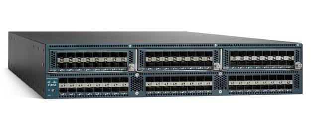
Cisco UCS 6200 Series Fabric Interconnects provide high-bandwidth, low-latency connectivity for servers, with integrated, unified management provided for all connected devices by Cisco UCS Manager. Deployed in redundant pairs, Cisco fabric interconnects offer the full active-active redundancy, performance, and exceptional scalability needed to support the large number of nodes that are typical in clusters serving big data applications. Cisco UCS Manager enables rapid and consistent server configuration using service profiles, automating ongoing system maintenance activities such as firmware updates across the entire cluster as a single operation. Cisco UCS Manager also offers advanced monitoring with options to raise alarms and send notifications about the health of the entire cluster.
Figure 1 Cisco UCS 6296UP 96-Port Fabric Interconnect
Cisco UCS C-Series Rack Mount Servers
Cisco UCS C-Series Rack Mount C240 M4 Rack servers (Large Form Factor Disk Drive Model) and Cisco UCS C-Series Rack Mount C220 M4 Rack servers (Small Form Factor Disk Drive Model) are enterprise-class systems that support a wide range of computing, I/O, and storage-capacity demands in compact designs. Cisco UCS C-Series Rack-Mount Servers are based on Intel Xeon E5-2600 v3 product family and 12-Gbps SAS throughput, delivering significant performance and efficiency gains over the previous generation of servers. The servers use dual Intel Xeon processor E5-2600 v3 series CPUs and support up to 768 GB of main memory (128 or 256 GB is typical for big data applications) and a range of disk drive and SSD options. With 2x1 Gigabit Ethernet embedded LAN-on-motherboard (LOM) ports. Cisco UCS virtual interface cards 1227 (VICs) designed for the M4 generation of Cisco UCS C-Series Rack Servers are optimized for high-bandwidth and low-latency cluster connectivity, with support for up to 256 virtual devices that are configured on demand through Cisco UCS Manager.
Figure 2 Cisco UCS C240 M4 Rack Server (Large Form Factor Disk Drive Model)
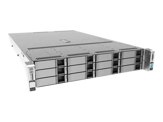
Figure 3 Cisco UCS C220 M4 Rack Server (Small Form Factor Disk Drive Model)

Cisco UCS Virtual Interface Cards (VICs)
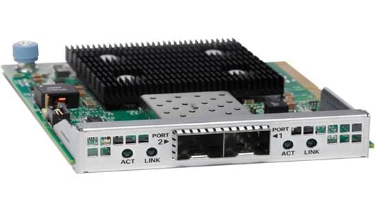
Cisco UCS Virtual Interface Cards (VICs), unique to Cisco, Cisco UCS Virtual Interface Cards incorporate next-generation converged network adapter (CNA) technology from Cisco, and offer dual 10-Gbps ports designed for use with Cisco UCS C-Series Rack-Mount Servers. Optimized for virtualized networking, these cards deliver high performance and bandwidth utilization and support up to 256 virtual devices. The Cisco UCS Virtual Interface Card (VIC) 1227 is a dual-port, Enhanced Small Form-Factor Pluggable (SFP+), 10 Gigabit Ethernet and Fibre Channel over Ethernet (FCoE)-capable, PCI Express (PCIe) modular LAN on motherboard (mLOM) adapter. It is designed exclusively for the M4 generation of Cisco UCS C-Series Rack Servers and the C3160 dense storage servers.
Figure 4 Cisco UCS VIC 1227
Cisco UCS Manager
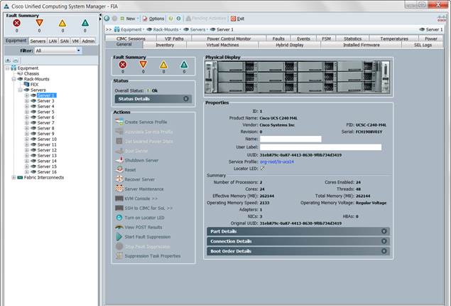
Cisco UCS Manager resides within the Cisco UCS 6200 Series Fabric Interconnects. It makes the system self-aware and self-integrating, managing all of the system components as a single logical entity. Cisco UCS Manager can be accessed through an intuitive graphical user interface (GUI), a command-line interface (CLI), or an XML application-programming interface (API). Cisco UCS Manager uses service profiles to define the personality, configuration, and connectivity of all resources within Cisco UCS, radically simplifying provisioning of resources so that the process takes minutes instead of days. This simplification allows IT departments to shift their focus from constant maintenance to strategic business initiatives.
Figure 5 Cisco UCS Manager
IBM BigInsights for Apache Hadoop: A Complete Hadoop Platform
IBM introduced new capabilities for analysts, data scientists, and administrators, as described below in IBM BigInsights for Apache Hadoop, to address the challenges faced by them.
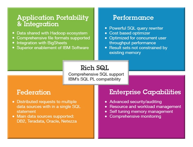
For Analysts, the IBM BigInsights Analyst module includes Big SQL and BigSheets.
Big SQL
Big SQL enables analysts to leverage IBM's strength in SQL engines to provide ANSI SQL access to data across any system from Hadoop, via JDBC or ODBC - seamlessly whether that data exists in Hadoop or a relational database. This means that developers familiar with the SQL programming language can access data in Hadoop without having to learn new languages or skills.
With Big SQL, all of your big data is SQL accessible. It presents a structured view of your existing data, using an optimal execution strategy, given available resources. Big SQL can leverage MapReduce parallelism when needed for complex data sets and avoid it when it hinders, using direct access for smaller, and low-latency queries.
Big SQL offers the following capabilities:
· Low-latency queries enabled by massively parallel processing (MPP) technology
· Query rewrite optimization and cost-based optimizer
· Integration of both Hive and HBase data sources
· Unparalleled support for ANSI SQL Standard
· Federated query access to IBM DB2®, Oracle, Teradata and ODBC sources
Big SQL supports the most common use cases for modernizing and building next-generation logical data warehouses:
· Offload data and workloads from existing data warehouses
· Move rarely used data out of high-cost data warehouses by creating query able archives in Hadoop
· Enable rapid prototyping of business intelligence reports
· Support rapid adoption of Hadoop by using existing SQL skills, without compromising on data security
Figure 6 Big SQL, BigSheets Value
BigSheets
BigSheets makes Do It Yourself Analytics into a reality for Analysts by going beyond structured database management into unstructured data management. Seeing the whole picture will help all levels of business make better decisions.
BigSheets provides a web-based, spreadsheet-style view into collections of files in Hadoop. Users can perform data transformations, filtering and visualizations at massive scale. No coding is required because BigSheets translates the spreadsheet actions into MapReduce to leverage the computational resources of the Hadoop cluster. This helps analysts discover value in data quickly and easily.
BigSheets is an extension of the mashup paradigm that:
· Integrates gigabytes, terabytes, or petabytes of unstructured data from web-based repositories
· Collects a wide range of unstructured web data stemming from user-defined seed URLs
· Extracts and enriches that data using the unstructured information management architecture you choose (LanguageWare, OpenCalais, etc.)
· Lets users explore and visualize this data in specific, user defined contexts (such as ManyEyes).
Some of the BigSheets benefits include:
· Provides business users with a new approach to keep pace with data escalation. By taking the structure to the data, this helps mine petabytes of data without additional storage requirements.
· BigSheets provides business users with a new approach that allows them to break down data into consumable, situation-specific frames of reference. This enables organizations to translate untapped, unstructured, and often unknown web data into actionable intelligence.
· Leverage all the compute resources of the Hadoop cluster to drive insights and visualizations with BigSheets right on the cluster—no extraction required
Big R
For Data Scientists, the IBM BigInsights Data Scientist module includes Big R.
Big R enables data scientists to run native R functions to explore, visualize, transform and model big data right from within the R environment. Data scientists can now run scalable machine learning algorithms with a wide class of algorithms and growing R-like syntax for new algorithms & customize existing algorithms. BigInsights for Apache Hadoop running Big R can use the entire cluster memory, spill to disk and run thousands of models in parallel.
Big R provides a new processing engine enables automatic tuning of machine learning performance over massive data sets in Hadoop clusters. Big R can be used for comprehensive data analysis, hiding some of the complexity of manually writing MapReduce jobs.
Benefits of Big R includes:
· End-to-end integration with open source R
· Transparent execution on Hadoop
· Seamless access to rich and scalable machine learning algorithms provided in Big R
· Text analytics to extract meaningful information from unstructured data
Text Analytics
A sophisticated text analytics capability unique to BigInsights allows developers to easily build high-quality applications able to process text in multiple written languages, and derive insights from large amounts of native textual data in various formats.
Enterprise Management
For Administrators, the IBM BigInsights Enterprise Management module provides:
A comprehensive web-based interface included in BigInsights simplifies cluster management, service management, job management and file management. Administrators and users can share the same interface, launching applications and viewing a variety of configurable reports and dashboards.
Built-in Security
BigInsights was designed with security in mind, supporting Kerberos authentication and providing data privacy, masking and granular access controls with auditing and monitoring functions to help ensure that the environments stays secure.
Requirements
Rack and PDU Configuration
Each rack consists of two vertical PDUs. The master rack consists of two Cisco UCS 6296UP Fabric Interconnects, and sixteen Cisco UCS C240 M4 Servers, three C220 M4 Servers, connected to each of the vertical PDUs for redundancy; thereby, ensuring availability during power source failure. The expansion racks consists of sixteen Cisco UCS C240 M4 Servers are connected to each of the vertical PDUs for redundancy; thereby, ensuring availability during power source failure, similar to the master rack.
![]() Please contact your Cisco representative for country specific information.
Please contact your Cisco representative for country specific information.
Describes the Rack Configurations of Rack 1 (Master Rack) and Racks 2–4 (Expansion Rack).
| Cisco 42URack |
Master Rack |
|
Cisco 42URack |
Expansion Rack |
| 42 |
Cisco UCS FI 6296UP |
|
42 |
Unused |
| 41 |
|
|
41 |
Unused |
| 40 |
Cisco UCS FI 6296UP |
|
40 |
Unused |
| 39 |
|
|
39 |
Unused |
| 38 |
Unused |
|
38 |
Unused |
| 37 |
Unused |
|
37 |
Unused |
| 36 |
Unused |
|
36 |
Unused |
| 35 |
Cisco UCS C220 M4 |
|
35 |
Unused |
| 34 |
Cisco UCS C220 M4 |
|
34 |
Unused |
| 33 |
Cisco UCS C220 M4 |
|
33 |
Unused |
| 32 |
|
|
32 |
|
| 31 |
Cisco UCS C240 M4 |
|
31 |
Cisco UCS C240 M4 |
| 30 |
|
|
30 |
|
| 29 |
Cisco UCS C240 M4 |
|
29 |
Cisco UCS C240 M4 |
| 28 |
|
|
28 |
|
| 27 |
Cisco UCS C240 M4 |
|
27 |
Cisco UCS C240 M4 |
| 26 |
|
|
26 |
|
| 25 |
Cisco UCS C240 M4 |
|
25 |
Cisco UCS C240 M4 |
| 24 |
|
|
24 |
|
| 23 |
Cisco UCS C240 M4 |
|
23 |
Cisco UCS C240 M4 |
| 22 |
|
|
22 |
|
| 21 |
Cisco UCS C240 M4 |
|
21 |
Cisco UCS C240 M4 |
| 20 |
|
|
20 |
|
| 19 |
Cisco UCS C240 M4 |
|
19 |
Cisco UCS C240 M4 |
| 18 |
|
|
18 |
|
| 17 |
Cisco UCS C240 M4 |
|
17 |
Cisco UCS C240 M4 |
| 16 |
|
|
16 |
|
| 15 |
Cisco UCS C240 M4 |
|
15 |
Cisco UCS C240 M4 |
| 14 |
|
|
14 |
|
| 13 |
Cisco UCS C240 M4 |
|
13 |
Cisco UCS C240 M4 |
| 12 |
|
|
12 |
|
| 11 |
Cisco UCS C240 M4 |
|
11 |
Cisco UCS C240 M4 |
| 10 |
|
|
10 |
|
| 9 |
Cisco UCS C240 M4 |
|
9 |
Cisco UCS C240 M4 |
| 8 |
|
|
8 |
|
| 7 |
Cisco UCS C240 M4 |
|
7 |
Cisco UCS C240 M4 |
| 6 |
|
|
6 |
|
| 5 |
Cisco UCS C240 M4 |
|
5 |
Cisco UCS C240 M4 |
| 4 |
|
|
4 |
|
| 3 |
Cisco UCS C240 M4 |
|
3 |
Cisco UCS C240 M4 |
| 2 |
|
|
2 |
|
| 1 |
Cisco UCS C240 M4 |
|
1 |
Cisco UCS C240 M4 |
Port Configuration on Fabric Interconnects
| Port Type |
Port Number |
| Network |
1 |
| Server |
2 to 68 |
Server Configuration and Cabling
The Cisco UCS C240 M4 rack server is equipped with Intel Xeon E5-2680 v3 processors, 256 GB of memory, Cisco UCS Virtual Interface Card 1227, Cisco 12-Gbps SAS Modular Raid Controller with 2-GB FBWC, 12 4TB SAS LFF Hard Disk Drive, 2 120-GB SATA SSD for Boot. Optionally, 480-GB SATA SSD for Boot can be used in place of the 120 GB.
The Cisco UCS C220 M4 rack server is equipped with Intel Xeon E5-2680 v3 processors, 256 GB of memory, Cisco UCS Virtual Interface Card 1227, Cisco 12-Gbps SAS Modular Raid Controller with 2-GB FBWC, 8 600GB 10K SAS SFF Hard Disk Drive, 2 120-GB SATA SSD for Boot.
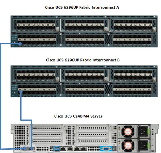
Figure 7 illustrates the port connectivity between the Fabric Interconnect and Cisco UCS C240 M4 server. Sixteen Cisco UCS C240 M4 servers are used in Master rack configurations.
Figure 7 Fabric Topology for Cisco UCS C240 M4
For more information on physical connectivity and single-wire management see:
For more information on physical connectivity illustrations and cluster setup, see:
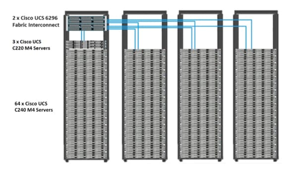
Figure 8 below depicts a 67 node cluster. Every server is connected to both Fabric Interconnect represented with dual link each with a 10 Gigabit Ethernet connectivity.
For more information on physical connectivity and single-wire management see:
For more information on physical connectivity illustrations and cluster setup, see:
Figure 8 below depicts a 67 node cluster. Each link in the figure represents 16 x 10 Gigabit Ethernet link from each of the 16 servers connecting to a Fabric Interconnect as a Direct Connect. Every server is connected to both Fabric Interconnect represented with dual link.
Figure 8 67 Nodes Cluster Configuration
Software Distributions and Versions
The software distribution required versions are listed below.
IBM BigInsights for Apache Hadoop
IBM InfoSphere BigInsights 3.0.0.0 is the version used in the document. For more information go to http://www-01.ibm.com/software/data/infosphere/biginsights/
Red Hat Enterprise Linux (RHEL)
The operating system supported is Red Hat Enterprise Linux 6.5. For more information visit http://www.redhat.com
Software Versions
The software versions tested and validated in this document are shown in Table 1.
| Layer |
Component |
Version or Release |
| Compute
|
Cisco UCS C240-M4 |
C240M4.2.0.3d |
| Cisco UCS C220-M4 |
C220M4.2.0.3d |
|
| Network |
Cisco UCS 6296UP |
UCS 2.2(3d)A |
| Cisco UCS VIC1227 Firmware |
4.0(1d) |
|
| Cisco UCS VIC1227 Driver |
2.1.1.66 |
|
| Storage |
LSI SAS 3108 |
24.5.0-0020 |
| Software
|
Red Hat Enterprise Linux Server |
6.5 (x86_64) |
| Cisco UCS Manager |
2.2(3d) |
|
| IBM InfoSphere BigInsights Enterprise Edition |
3.0.0.0 |
![]() The latest drivers can be downloaded from the link: https://software.cisco.com/download/release.html?mdfid=283862063&flowid=25886&softwareid=283853158&release=1.5.7d&relind=AVAILABLE&rellifecycle=&reltype=latest
The latest drivers can be downloaded from the link: https://software.cisco.com/download/release.html?mdfid=283862063&flowid=25886&softwareid=283853158&release=1.5.7d&relind=AVAILABLE&rellifecycle=&reltype=latest
![]() The Latest Supported RAID controller Driver is already included with the RHEL 6.5 operating system.
The Latest Supported RAID controller Driver is already included with the RHEL 6.5 operating system.
![]() Cisco UCS C240/C220 M4 Rack Servers are supported from Cisco UCS firmware 2.2(3d) onwards.
Cisco UCS C240/C220 M4 Rack Servers are supported from Cisco UCS firmware 2.2(3d) onwards.
Architecture
Fabric Configuration
This section provides details for configuring a fully redundant, highly available Cisco UCS 6296 fabric configuration.
1. Initial setup of the Cisco UCS Fabric Interconnect A and B.
2. Connect to UCS Manager using virtual IP address of using the web browser.
3. Launch UCS Manager.
4. Enable server and uplink ports.
5. Start discovery process.
6. Create pools and polices for service profile template.
7. Create Service Profile template and 67 Service profiles.
8. Associate Service Profiles to servers.
Performing Initial Setup of Cisco UCS 6296 Fabric Interconnects
This section describes the steps to perform initial setup of the Cisco UCS 6296 Fabric Interconnects A and B.
Configure Fabric Interconnect A
1. Connect to the console port on the first Cisco UCS 6296 Fabric Interconnect.
2. At the prompt to enter the configuration method, enter console to continue.
3. If asked to either perform a new setup or restore from backup, enter setup to continue.
4. Enter y to continue to set up a new Cisco UCS Fabric Interconnect.
5. Enter y to enforce strong passwords.
6. Enter the password for the admin user.
7. Enter the same password again to confirm the password for the admin user.
8. When asked if this fabric interconnect is part of a cluster, answer y to continue.
9. Enter A for the switch fabric.
10. Enter the cluster name for the system name.
11. Enter the Mgmt0 IPv4 address.
12. Enter the Mgmt0 IPv4 netmask.
13. Enter the IPv4 address of the default gateway.
14. Enter the cluster IPv4 address.
15. To configure DNS, answer y.
16. Enter the DNS IPv4 address.
17. Answer y to set up the default domain name.
18. Enter the default domain name.
19. Review the settings that were printed to the console, and if they are correct, answer yes to save the configuration.
20. Wait for the login prompt to make sure the configuration has been saved.
Configure Fabric Interconnect B
1. Connect to the console port on the second Cisco UCS 6296 Fabric Interconnect.
2. When prompted to enter the configuration method, enter console to continue.
3. The installer detects the presence of the partner Cisco UCS Fabric Interconnect and adds this fabric interconnect to the cluster. Enter y to continue the installation.
4. Enter the admin password that was configured for the first Fabric Interconnect.
5. Enter the Mgmt0 IPv4 address.
6. Answer yes to save the configuration.
7. Wait for the login prompt to confirm that the configuration has been saved.
For more information on configuring Cisco UCS 6200 Series Fabric Interconnect, see:
Logging Into Cisco UCS Manager
1. Open a Web browser and navigate to the Cisco UCS 6296 Fabric Interconnect cluster address.
2. Click the Launch link to download the Cisco UCS Manager software.
3. If prompted to accept security certificates, accept as necessary.
4. When prompted, enter admin for the username and enter the administrative password.
5. Click Login to log in to the Cisco UCS Manager.
Upgrading Cisco UCS Manager Software to Version 2.2(3d)
This document assumes the use of Cisco UCS Manager 2. 2(3d). Refer to Upgrading between Cisco UCS Manager 2.0 Releases to upgrade the Cisco UCS Manager software and UCS 6296 Fabric Interconnect software to version 2.2(3d). Also, make sure the Cisco UCS Manager C-Series version 2.2(3d) software bundles are installed on the Fabric Interconnects.
Managing Licenses for Additional Ports
Each Cisco UCS Fabric Interconnect comes with several port licenses that are factory installed and shipped with the hardware. Cisco UCS Fabric interconnects can be purchased fully licensed or partially licensed. Additional licenses can also be purchased after delivery. To install the additional licenses required for this 67 server cluster as followed in the CVD, follow the details provided in Managing Licenses. The Bill of Materials provides details for the additional licenses required.
Adding a Block of IP Addresses for KVM Access
These steps provide details for creating a block of KVM IP addresses for server access in the Cisco UCS environment.
To add a block of IP addresses, complete the following steps:
1. Select the LAN tab at the top of the left window.
2. Select Pools > IpPools > Ip Pool ext-mgmt.
3. Right-click IP Pool ext-mgmt.
4. Select Create Block of IPv4 Addresses.
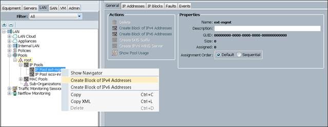
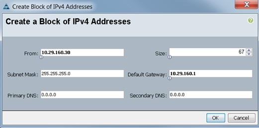
5. Enter the starting IP address of the block and number of IPs needed, as well as the subnet and
gateway information.
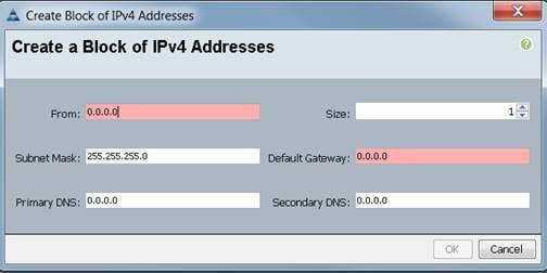
6. Click OK to create the IP block.
7. Click OK in the message box.
Enabling Uplink Port
To enable uplink ports, complete the following steps:
1. Select the Equipment tab on the top left of the window.
2. Select Equipment > Fabric Interconnects > Fabric Interconnect A (primary) > Fixed Module.
3. Expand the Unconfigured Ethernet Ports section.
4. Select port 1 that is connected to the uplink switch, right-click, then select Reconfigure > Configure as Uplink Port.
5. Select Show Interface and select 10GB for Uplink Connection.
6. A pop-up window appears to confirm your selection. Click Yes, then OK to continue.
7. Select Equipment > Fabric Interconnects > Fabric Interconnect B (subordinate) > Fixed Module.
8. Expand the Unconfigured Ethernet Ports section.
9. Select port number 1, which is connected to the uplink switch, right-click, then select Reconfigure > Configure as Uplink Port.
10. Select Show Interface and select 10GB for Uplink Connection.
11. A pop-up window appears to confirm your selection. Click Yes, then OK to continue.

Configuring VLANs
VLANs are configured as in shown in Table 2.
| VLAN |
Fabric |
NIC Port |
Function |
Failover |
| default(VLAN1) |
A |
eth0 |
Management, User connectivity |
Fabric Failover to B |
| vlan11_DATA1 |
B |
eth1 |
Hadoop |
Fabric Failover to A |
| vlan12_DATA2 |
A |
eth2 |
Hadoop with multiple NICs support |
Fabric Failover to B |
All of the VLANs created need to be trunked to the upstream distribution switch connecting the fabric interconnects. For this deployment, default VLAN1 is configured for management access (installing and configuring OS, clustershell commands, setup NTP, user connectivity, etc.), and vlan11_DATA1 is configured for Hadoop Data traffic.
With some Hadoop distributions supporting multiple NICs, where Hadoop uses multiple IP subnets for its data traffic, vlan12_DATA2 can be configured to carry Hadoop Data traffic allowing use of both the Fabrics (10 GigE on each Fabric allowing 20Gbps active-active connectivity).
Further, if there are other distributed applications co-existing in the same Hadoop cluster, then these applications could use vlan12_DATA2 providing full 10GigE connectivity to this application on a different fabric without affecting Hadoop Data traffic (here Hadoop is not enabled for multi-NIC).
![]() Use the default VLAN1 for management traffic.
Use the default VLAN1 for management traffic.
To configure VLANs in the Cisco UCS Manager GUI, complete the following steps:
1. Select the LAN tab in the left pane in the UCSM GUI.
2. Select LAN > VLANs.
3. Right-click the VLANs under the root organization.
4. Select Create VLANs to create the VLAN.

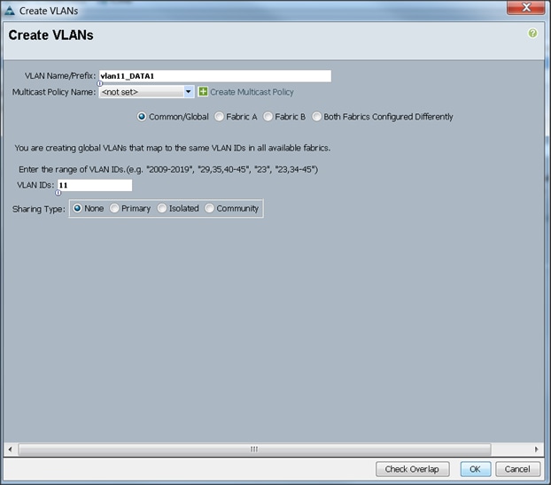
5. Enter vlan11_DATA1 for the VLAN Name.
6. Select Common/Global for the vlan11_DATA1.
7. Enter 11 on VLAN IDs of the Create VLAN IDs.
8. Click OK and then, click Finish.
9. Click OK in the success message box.
10. Select the LAN tab in the left pane again
11. Select LAN > VLANs.
12. Right-click the VLANs under the root organization.
13. Select Create VLANs to create the VLAN.
14. Enter vlan12_DATA2 for the VLAN Name.
15. Select Common/Global for the vlan12_DATA2.
16. Enter 12 on VLAN IDs of the Create VLAN IDs.
17. Click OK and then, click Finish.
Final list of VLANs created, as shown below:

Enabling Server Ports
To enable server ports, complete the following steps:
1. Select the Equipment tab on the top left of the window.
2. Select Equipment > Fabric Interconnects > Fabric Interconnect A (primary) > Fixed Module.
3. Expand the Unconfigured Ethernet Ports section.
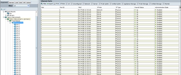
4. Select all the ports that are connected to the Servers right-click them, and select Reconfigure > Configure as a Server Port.
5. A pop-up window appears to confirm your selection. Click Yes, then OK to continue.
6. Select Equipment > Fabric Interconnects > Fabric Interconnect B (subordinate) > Fixed Module.
7. Expand the UnConfigured Ethernet Ports section.
8. Select all the ports that are connected to the Servers right-click them, and select Reconfigure > Configure as a Server Port.
9. A pop-up window appears to confirm your selection. Click Yes, then OK to continue.

Creating Pools for Service Profile Templates
Creating an Organization
Organizations are used as a means to arrange and restrict access to various groups within the IT organization, thereby enabling multi-tenancy of the compute resources. This document does not assume the use of Organizations; however the necessary steps are provided for future reference.
To configure an organization within the Cisco UCS Manager GUI, complete the following steps:
1. Click New on the top left corner in the right pane in the Cisco UCS Manager GUI.
2. Select Create Organization from the options
3. Enter a name for the organization.
4. (Optional) Enter a description for the organization.
5. Click OK.
6. Click OK in the success message box.
Creating MAC Address Pools
To create MAC address pools, complete the following steps:
1. Select the LAN tab on the left of the window.
2. Select Pools > root.
3. Right-click MAC Pools under the root organization.
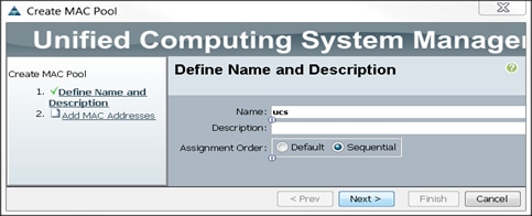
4. Select Create MAC Pool to create the MAC address pool. Enter ucs for the name of the MAC pool.
5. (Optional) Enter a description of the MAC pool.
6. Select Assignment Order Sequential.
7. Click Next.
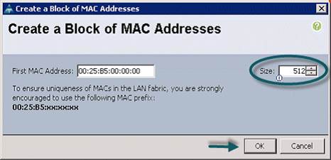
8. Click Add.
9. Specify a starting MAC address.
10. Specify a size of the MAC address pool, which is sufficient to support the available server resources.
11. Click OK.
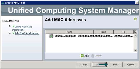
12. Click Finish.
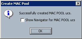
13. When the message box displays, click OK.
Creating a Server Pool
A server pool contains a set of servers. These servers typically share the same characteristics. Those characteristics can be their location in the chassis, or an attribute such as server type, amount of memory, local storage, type of CPU, or local drive configuration. You can manually assign a server to a server pool, or use server pool policies and server pool policy qualifications to automate the assignment
To configure the server pool within the Cisco UCS Manager GUI, complete the following steps:
1. Select the Servers tab in the left pane in the Cisco UCS Manager GUI.
2. Select Pools > root.
3. Right-click the Server Pools.
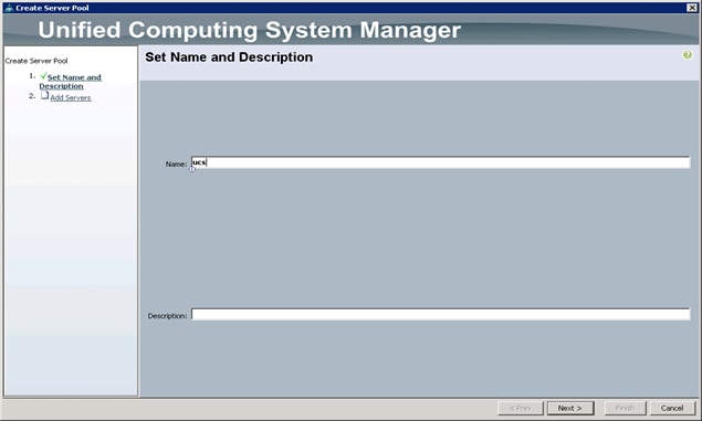
4. Select Create Server Pool.
5. Enter your required name (ucs) for the Server Pool in the name text box.
6. (Optional) enter a description for the organization.
7. Click Next > to add the servers.
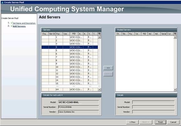
8. Select all the Cisco UCS C240 M4L servers to be added to the server pool you previously created (ucs), then Click >> to add them to the pool.
9. Click Finish.
10. Click OK and then click Finish.
Creating Policies for Service Profile Templates
Creating Host Firmware Package Policy
Firmware management policies allow the administrator to select the corresponding packages for a given server configuration. These include adapters, BIOS, board controllers, FC adapters, HBA options, ROM and storage controller properties as applicable.
To create a firmware management policy for a given server configuration using the Cisco UCS Manager GUI, complete the following steps:
1. Select the Servers tab in the left pane in the Cisco UCS Manager GUI.
2. Select Policies > root.
3. Right-click Host Firmware Packages.
4. Select Create Host Firmware Package.
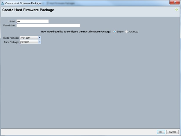
5. Enter your required Host Firmware package name (ucs).
6. Select Simple radio button to configure the Host Firmware package.
7. Select the appropriate Rack package that you have.
8. Click OK to complete creating the management firmware package.
9. Click OK.
Creating QoS Policies
To create the QoS policy for a given server configuration using the Cisco UCS Manager GUI, complete the following steps:
Best Effort Policy
1. Select the LAN tab in the left pane in the Cisco UCS Manager GUI.
2. Select Policies > root.
3. Right-click QoS Policies.
4. Select Create QoS Policy.
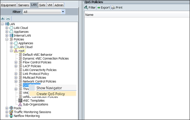
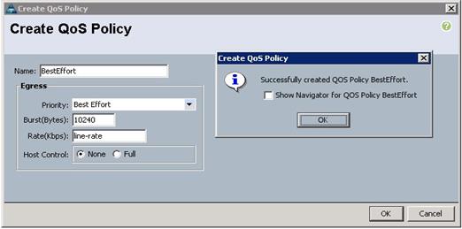
5. Enter BestEffort as the name of the policy.
6. Select BestEffort from the drop down menu.
7. Keep the Burst(Bytes) field as default (10240).
8. Keep the Rate(Kbps) field as default (line-rate).
9. Keep Host Control radio button as default (none).
10. Once the pop-up window appears, click OK to complete the creation of the Policy.
11. Select the LAN tab in the left pane in the Cisco UCS Manager GUI.
12. Select Policies > root.
13. Right-click QoS Policies.
14. Select Create QoS Policy.
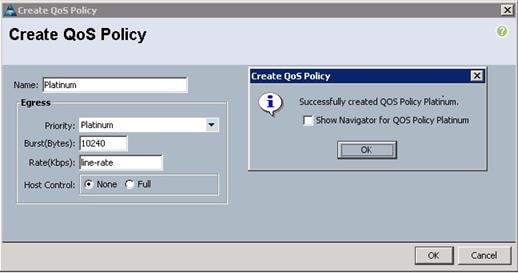
15. Enter Platinum as the name of the policy.
16. Select Platinum from the drop down menu.
17. Keep the Burst(Bytes) field as default (10240).
18. Keep the Rate(Kbps) field as default (line-rate).
19. Keep Host Control radio button as default (none).
20. Once the pop-up window appears, click OK to complete the creation of the Policy.
Setting Jumbo Frames
To set Jumbo frames and enabling QoS, complete the following steps:
1. Select the LAN tab in the left pane in the Cisco UCS Manager GUI.
2. Select LAN Cloud > QoS System Class.
3. In the right pane, select the General tab
4. In the Platinum row, enter 9000 for MTU.
5. Check the Enabled Check box next to Platinum.
6. In the Best Effort row, select best-effort for weight.
7. In the Fiber Channel row, select none for weight.
8. Click Save Changes.
9. Click OK.

Creating Local Disk Configuration Policy
To create local disk configuration in the Cisco UCS Manager GUI, complete the following steps:
1. Select the Servers tab on the left pane in the Cisco UCS Manager GUI.
2. Go to Policies > root.
3. Right-click Local Disk Configuration Policies.
4. Select Create Local Disk Configuration Policy.
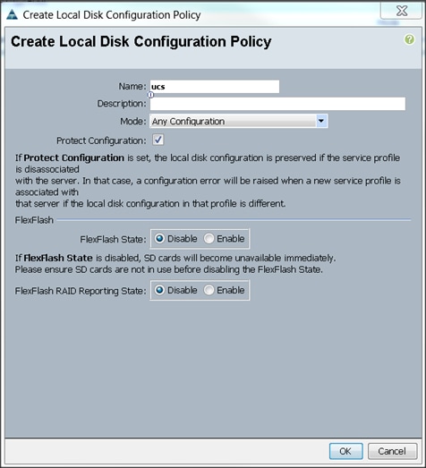
5. Enter ucs the local disk configuration policy name. as
6. Change the Mode to Any Configuration.
7. Check the Protect Configuration box.
8. Keep the FlexFlash State field as default (Disable).
9. Keep the FlexFlash RAID Reporting State field as default (Disable).
10. Click OK to complete the creation of the Local Disk Configuration Policy.
11. Click OK.
Creating Server BIOS Policy
The BIOS policy feature in Cisco UCS automates the BIOS configuration process. The traditional method of setting the BIOS is done manually and is often error-prone. By creating a BIOS policy and assigning the policy to a server or group of servers, you can enable transparency within the BIOS settings configuration.
![]() BIOS settings can have a significant performance impact, depending on the workload and the applications. The BIOS settings listed in this section is for configurations optimized for best performance which can be adjusted based on the application, performance and energy efficiency requirements.
BIOS settings can have a significant performance impact, depending on the workload and the applications. The BIOS settings listed in this section is for configurations optimized for best performance which can be adjusted based on the application, performance and energy efficiency requirements.
To create a server BIOS policy using the Cisco UCS Manager GUI, complete the following steps:
1. Select the Servers tab in the left pane in the UCS Manager GUI.
2. Select Policies > root.
3. Right-click BIOS Policies.
4. Select Create BIOS Policy.
5. Enter your preferred BIOS policy name (ucs).
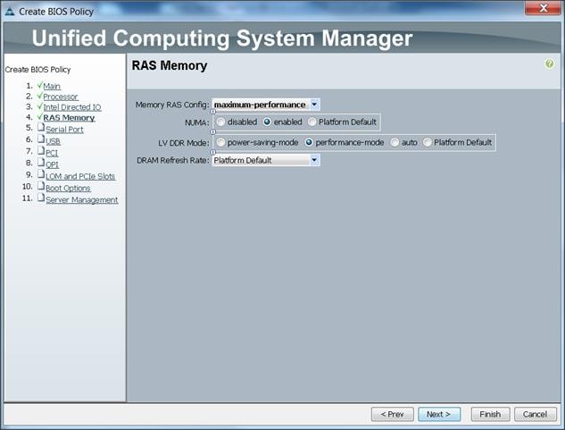
6. Change the BIOS settings as shown in the following figures:
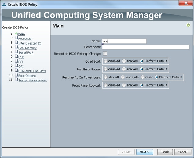
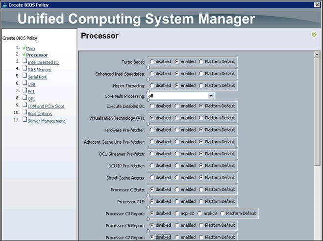
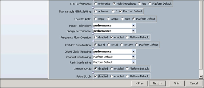
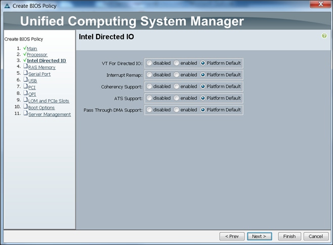
7. Click Finish to complete creating the BIOS policy.
8. Click OK.
Creating Boot Policy
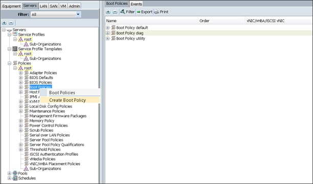
To create boot policies within the Cisco UCS Manager GUI, complete the following steps:
1. Select the Servers tab in the left pane in the Cisco UCS Manager GUI.
2. Select Policies > root.
3. Right-click the Boot Policies.
4. Select Create Boot Policy.
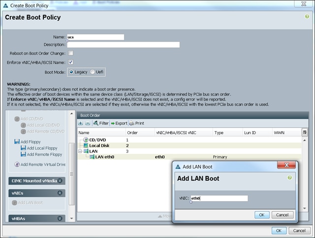
5. Enter ucs as the boot policy name.
6. (Optional) enter a description for the boot policy.
7. Keep the Reboot on Boot Order Change check box unchecked.
8. Keep Enforce vNIC/vHBA/iSCSI Name check box checked.
9. Keep Boot Mode Default (Legacy).
10. Expand Local Devices > Add CD/DVD and select Add Local CD/DVD.
11. Expand Local Devices and select Add Local Disk.
12. Expand vNICs and select Add LAN Boot and enter eth0.
13. Click OK to add the Boot Policy.
14. Click OK.
Creating Power Control Policy
To create Power Control policies within the Cisco UCS Manager GUI, complete the following steps:
1. Select the Servers tab in the left pane in the Cisco UCS Manager GUI.
2. Select Policies > root.
3. Right-click the Power Control Policies.
4. Select Create Power Control Policy.
5. Enter ucs as the Power Control policy name.
6. (Optional) enter a description for the boot policy.
7. Select No cap for Power Capping selection.
8. Click OK for the Power Control Policy.
9. Click OK.
Creating a Service Profile Template
To create a service profile template, complete the following steps:
1. Select the Servers tab in the left pane in the Cisco UCS Manager GUI.
2. Right-click Service Profile Templates.
3. Select Create Service Profile Template.

4. The Create Service Profile Template window appears.
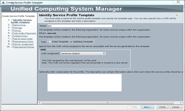
5. The steps below provide a detailed configuration procedure to identify the service profile template:
a. Name the service profile template as ucs. Select the Updating Template radio button.
b. In the UUID section, select Hardware Default as the UUID pool.
c. Click Next to continue to the next section.
Configuring Network Settings for the Template
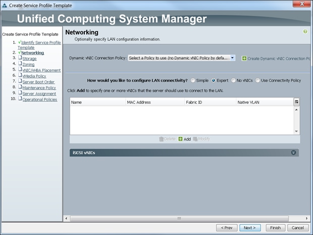
To configure network settings for the template, complete the following steps:
1. Keep the Dynamic vNIC Connection Policy field at the default.
2. Select Expert radio button for the option how would you like to configure LAN connectivity?
3. Click Add to add a vNIC to the template.
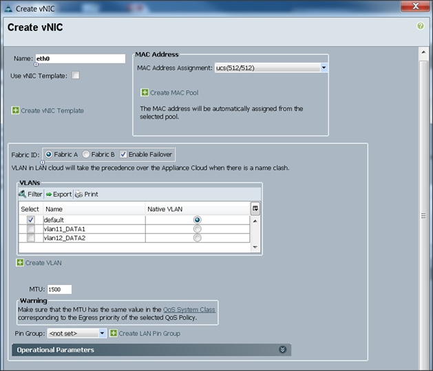
4. The Create vNIC window displays. Name the vNIC eth0.
5. Select ucs in the Mac Address Assignment pool.
6. Select the Fabric A radio button and check the Enable failover check box for the Fabric ID.
7. Check the default check box for VLANs and select the Native VLAN radio button.
8. Select MTU size as 1500
9. Select adapter policy as Linux
10. Select QoS Policy BestEffort.
11. Keep the Network Control Policy set to Default.
12. Keep the Connection Policies set to Dynamic vNIC.
13. Keep the Dynamic vNIC Connection Policy as <not set>.
14. Click OK.

15. Click Add to add a vNIC to the template.
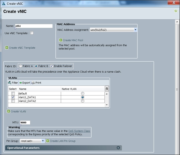
16. The Create vNIC window appears. Name the vNIC eth1.
17. Select ucs in the MAC Address Assignment pool.
18. Select the Fabric B radio button and check the Enable failover check box for the Fabric ID.
19. Check the vlan11_DATA1 check box for VLANs and select the Native VLAN radio button.
20. Select MTU size as 9000.
21. Select the adapter policy Linux.
22. Select QoS Policy Platinum.
23. Keep the Network Control Policy as Default.
24. Keep the Connection Policies as Dynamic vNIC.
25. Keep the Dynamic vNIC Connection Policy as <not set>.
26. Click OK.

27. Click Add to add a vNIC to the template.
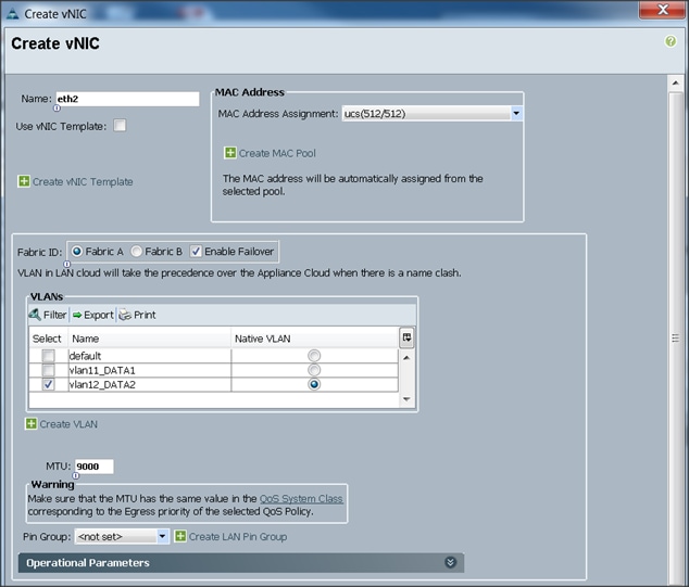
28. The Create vNIC window appears. Name the vNIC eth2.
29. Select ucs in the MAC Address Assignment pool.
30. Select the Fabric A radio button and check the Enable failover check box for the Fabric ID.
31. Check the vlan12_DATA2 check box for VLANs and select the Native VLAN radio button.
32. Select MTU size as 9000.
33. Select adapter policy as Linux.
34. Select QoS Policy as Platinum.
35. Keep the Network Control Policy as Default.
36. Keep the Connection Policies as Dynamic vNIC.
37. Keep the Dynamic vNIC Connection Policy as <not set>.
38. Click OK.

Configuring Storage Policy for the Template
To configure storage policies, complete the following steps:
1. Select ucs for the local disk configuration policy.
2. Select the No vHBAs radio button for the option for How would you like to configure SAN connectivity?
3. Click Next to continue to the next section.
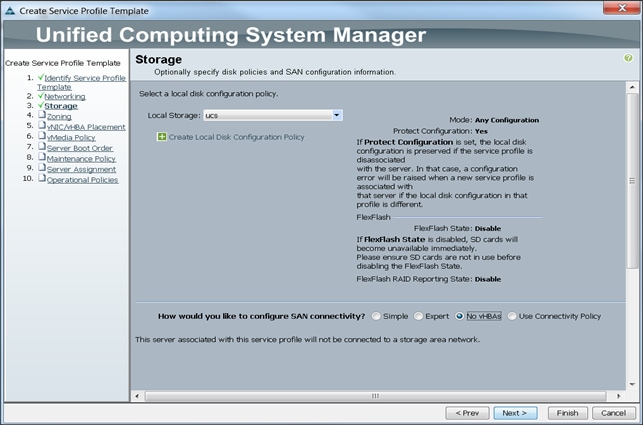
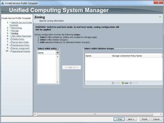
4. Click Next when the zoning window appears to go to the next section.
Configuring vNIC/vHBA Placement for the Template
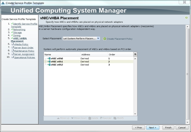
To configure vNIC/vHBA placement policy, complete the following steps:
1. Select the Default Placement Policy option for the Select Placement field.
2. Select eth0, eth1 and eth2 assign the vNICs in the following order:
a. eth0
b. eth1
c. eth2
3. Review to make sure that all of the vNICs were assigned in the appropriate order.
4. Click Next to continue to the next section.
Configuring the vMedia Policy for the Template
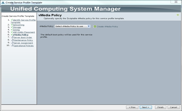
To configure the vMedia Policy for the template, complete the following steps:
1. Click Next when the vMedia Policy window appears to go to the next section.
Configuring Server Boot Order for the Template
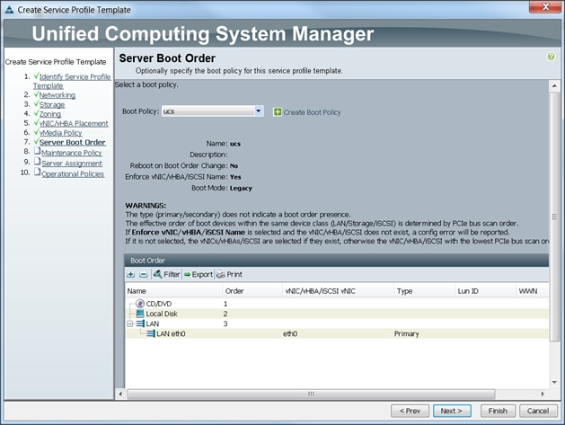
To set the boot order for servers, complete the following steps:
1. Select ucs in the Boot Policy name field.
2. Review to make sure that all of the boot devices were created and identified.
3. Verify that the boot devices are in the correct boot sequence.
4. Click OK.
5. Click Next to continue to the next section.
In the Maintenance Policy window, to apply the maintenance policy, complete the following steps:
6. Keep the Maintenance policy at no policy used by default.
7. Click Next to continue to the next section.
Configuring Server Assignment for the Template
In the Server Assignment window, to assign the servers to the pool, complete the following steps:
1. Select ucs for the Pool Assignment field.
2. Keep the Server Pool Qualification field at default.
3. Select ucs in Host Firmware Package.
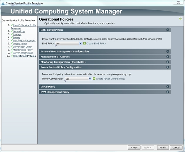
Configuring Operational Policies for the Template
In the Operational Policies Window, to configure operational policies for the template, complete the following steps:
1. Select ucs in the BIOS Policy field.
2. Select ucs in the Power Control Policy field.
3. Click Finish to create the Service Profile template.
4. Click OK in the pop-up window to proceed.
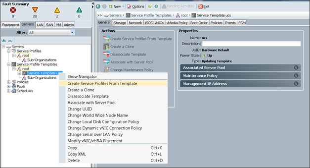
5. Select the Servers tab in the left pane of the UCS Manager GUI.
6. Go to Service Profile Templates > root.
7. Right-click Service Profile Templates ucs.
8. Select Create Service Profiles From Template.
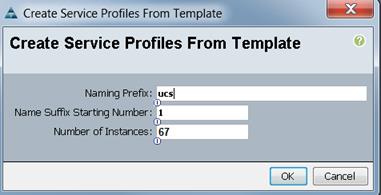
The Create Service Profile from Template window appears.
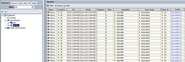
Association of the Service Profiles will take place automatically.
The Final Cisco UCS Manager window is shown below.
Configuring Disk Drives for the Operating System on Management Nodes
Namenode, Secondary Namenode, and job tracker have a different RAID configuration compared to Data nodes. These are three Cisco UCS C220 M4 Servers. This section details the configuration of disk drives for Operating System on these three Cisco C220 M4 servers (rhel1, rhel2 and rhel3). The first two disk drives are configured as RAID1, read ahead, cache is enabled, and write cache is enabled while battery is present. The first two disk drives (RAID 1) are used for operating system and remaining disk drives are used for data (any staging data) as described in the following sections.
![]() The Namenode, Secondary Namenode and Job tracker on Cisco C220 M4 are not used as data nodes.
The Namenode, Secondary Namenode and Job tracker on Cisco C220 M4 are not used as data nodes.
To configure Disk Drives for Operating System on Master Nodes (Cisco UCS C220 M4 servers) rhel1, rhel2 and rhel3, complete the following steps.
1. Log in to the Cisco UCS 6296 Fabric Interconnect and launch the Cisco UCS Manager application.
2. Select the Equipment tab.
3. In the navigation pane expand Rack-Mounts and then Servers.
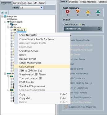
4. Right-click the server and select KVM Console.
5. Restart the server by using KVM Console, Macros > Static Macros > Ctrl-Alt-Del.
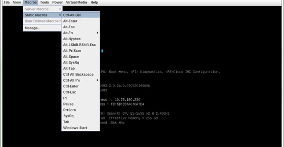
6. Press <Ctrl> - R to enter Cisco SAS Modular Raid Controller BIOS Configuration Utility.
7. Select the controller and press F2.
![]() Clear the Configuration if previous configurations are present.
Clear the Configuration if previous configurations are present.
8. Select Create Virtual Drive.
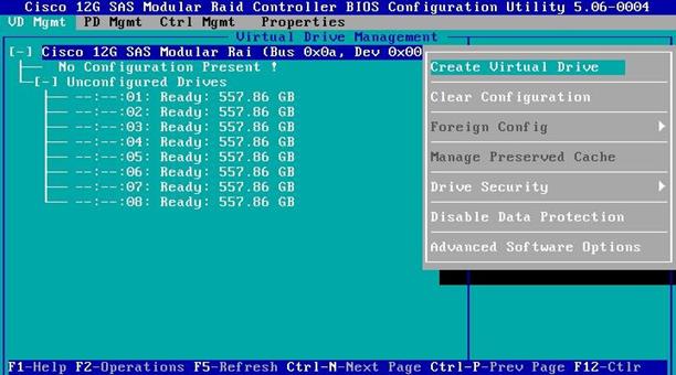
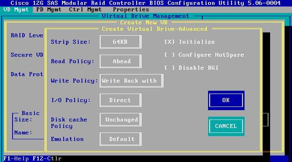
9. Select RAID level as RAID-1, select the first two drives and choose Advanced.
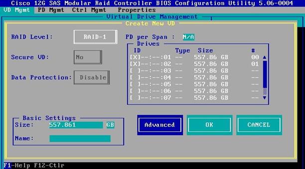
10. Select the following:
a. Strip Size is 64KB.
b. Read Policy is Ahead.
c. Write Policy is Write Back with BBU.
d. I/O Policy is Direct.
e. Disk Cache Policy is unchanged.
f. Emulation is Default.
11. Select Initialize.
![]() Initialization will destroy data on the virtual drives.
Initialization will destroy data on the virtual drives.
12. Select OK to continue.
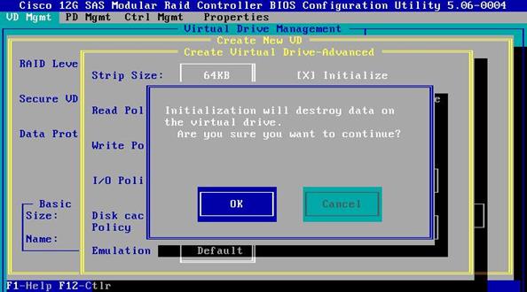
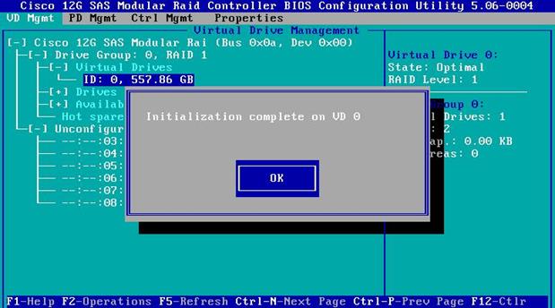
13. Select OK to continue.
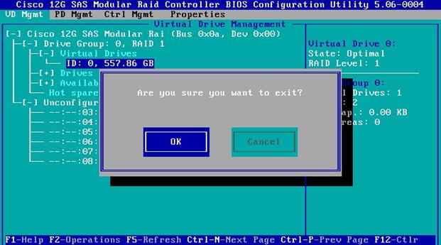
14. Press the ESC key, then select OK to exit the utility.
15. Restart the server by using KVM Console Menu, Macros > Static Macros > Ctrl-Alt-Del.
![]() The rest of the disk drives of the master nodes are configured using StorCli Command after installing the Operating System.
The rest of the disk drives of the master nodes are configured using StorCli Command after installing the Operating System.
Installing Red Hat Enterprise Linux 6.5 on C220 M4 Systems
There are multiple methods to install the Red Hat Linux operating system. The installation procedure described in this deployment guide uses the KVM console and virtual media from Cisco UCS Manager.
![]() RHEL 6.5 DVD/ISO is required for the installation.
RHEL 6.5 DVD/ISO is required for the installation.
To install the Red Hat Linux operating system, complete the following steps: Log in to the Cisco UCS 6296 Fabric Interconnect and launch the Cisco UCS Manager application.
1. Select the Equipment tab.
2. In the navigation pane expand Rack-Mounts and then Servers.
3. Right-click the server and select KVM Console.
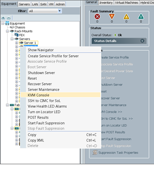
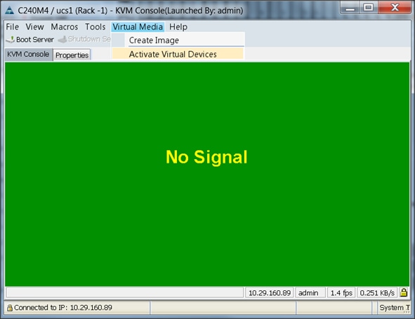
4. In the KVM window, select the Virtual Media tab.
5. Click the Activate Virtual Devices found in Virtual Media tab.
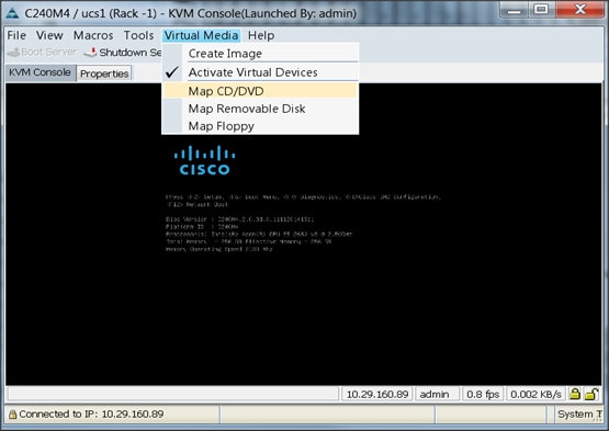
6. In the KVM window, select the Virtual Media tab and Click the Map CD/DVD.
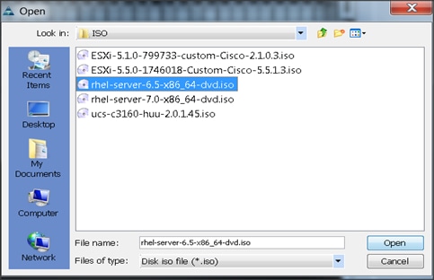
7. Browse to the Red Hat Enterprise Linux Server 6.5 installer ISO image file.
![]() The Red Hat Enterprise Linux 6.5 DVD is assumed to be on the client machine.
The Red Hat Enterprise Linux 6.5 DVD is assumed to be on the client machine.
8. Click Open to add the image to the list of virtual media.
9. In the KVM window, select the KVM tab to monitor during boot.
10. In the KVM window, select the Macros > Static Macros > Ctrl-Alt-Del button in the upper left corner.
11. Click OK.
12. Click OK to reboot the system.
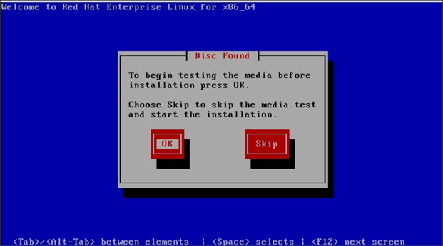
13. On reboot, the machine detects the presence of the Red Hat Enterprise Linux Server 6.5 install media.
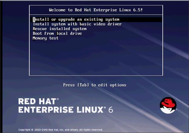
14. Select Install or Upgrade an Existing System.
15. Click Next.

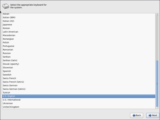
16. Select appropriate keyboard and click Next.
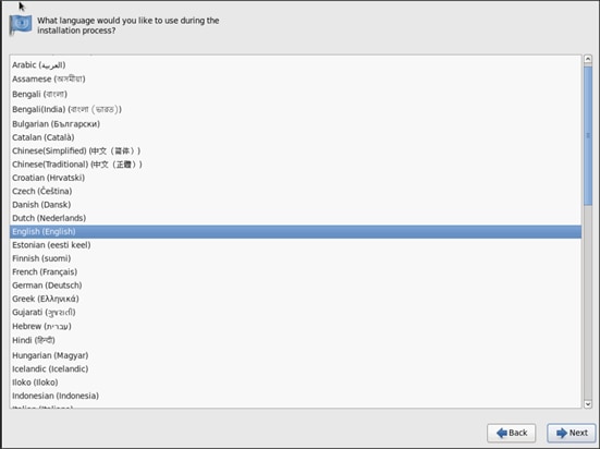
17. Select language of installation and click Next.
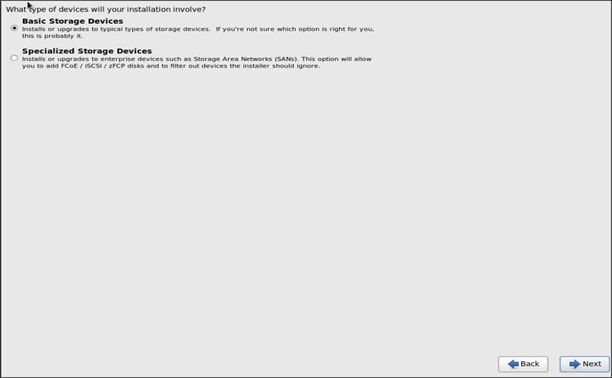
18. Select Basic Storage Devices and click Next.
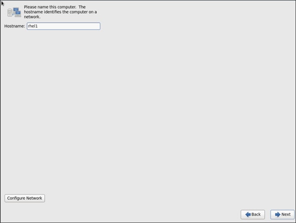
19. Provide the Hostname and click Next.
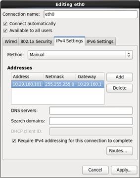
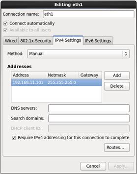
20. Configure Networking for the Host.
21. Select the appropriate Time Zone.
22. Click Skip to skip the media test and start the installation.
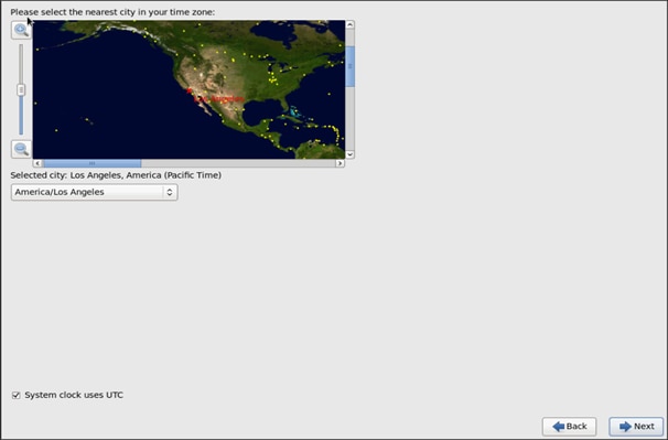
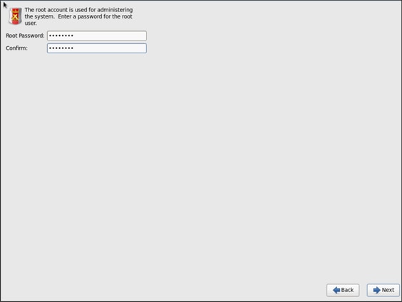
23. Enter the root Password and click Next.
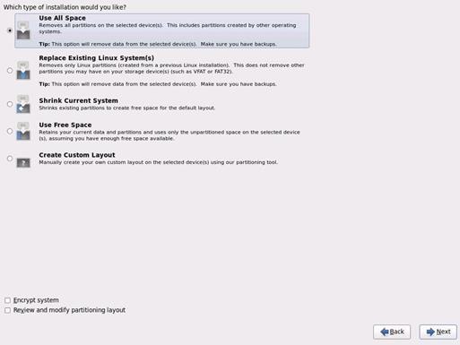
24. Choose Use All Space for Installation type. Click Next.
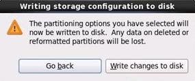
25. Click Write changes to disk.
26. Select Basic Server and click Next.
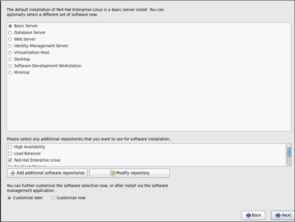
27. Once the installation is complete reboot the system.
28. Repeat the steps 1 to 28 to install Red Hat Enterprise Linux 6.5 on Servers 2 and 3.
![]() The OS installation and configuration of the nodes that is mentioned above can be automated through PXE boot or third party tools.
The OS installation and configuration of the nodes that is mentioned above can be automated through PXE boot or third party tools.
The hostnames and their corresponding IP addresses for all 67 nodes are shown in Table 3.
Table 3 Hostnames and IP Addresses
| Hostname |
eth0 |
eth1 |
eth2 |
| rhel1 |
10.29.160.101 |
192.168.11.101 |
192.168.12.101 |
| rhel2 |
10.29.160.102 |
192.168.11.102 |
192.168.12.102 |
| rhel3 |
10.29.160.103 |
192.168.11.103 |
192.168.12.103 |
| rhel4 |
10.29.160.104 |
192.168.11.104 |
192.168.12.104 |
| rhel5 |
10.29.160.105 |
192.168.11.105 |
192.168.12.105 |
| rhel6 |
10.29.160.106 |
192.168.11.106 |
192.168.12.106 |
| rhel7 |
10.29.160.107 |
192.168.11.107 |
192.168.12.107 |
| rhel8 |
10.29.160.108 |
192.168.11.108 |
192.168.12.108 |
| rhel9 |
10.29.160.109 |
192.168.11.109 |
192.168.12.109 |
| rhel10 |
10.29.160.110 |
192.168.11.110 |
192.168.12.110 |
| rhel11 |
10.29.160.111 |
192.168.11.111 |
192.168.12.111 |
| rhel12 |
10.29.160.112 |
192.168.11.112 |
192.168.12.112 |
| rhel13 |
10.29.160.113 |
192.168.11.113 |
192.168.12.113 |
| rhel14 |
10.29.160.114 |
192.168.11.114 |
192.168.12.114 |
| rhel15 |
10.29.160.115 |
192.168.11.115 |
192.168.12.115 |
| rhel16 |
10.29.160.116 |
192.168.11.116 |
192.168.12.116 |
| … |
… |
… |
… |
| rhel67 |
10.29.160.167 |
192.168.11.167 |
192.168.12.167 |
Installing Red Hat Enterprise Linux 6.5 using software RAID on Cisco UCS C240 M4 Systems
This section provides detailed procedures for installing Red Hat Enterprise Linux 6.5 using Software RAID (OS based Mirroring) on Cisco UCS C240 M4 servers (rhel4 through rhel67).
There are multiple methods to install the Red Hat Linux operating system. The installation procedure described in this deployment guide uses the KVM console and virtual media from Cisco UCS Manager.
![]() This requires RHEL 6.5 DVD/ISO for the installation.
This requires RHEL 6.5 DVD/ISO for the installation.
To install the Red Hat Linux operating system, complete the following steps:
1. Log in to the Cisco UCS 6296 Fabric Interconnect and launch the Cisco UCS Manager application.
2. Select the Equipment tab.
3. In the navigation pane expand Rack-Mounts and then Servers.
4. Right click on the server 4 and select KVM Console.
5. In the KVM window, select the Virtual Media tab.
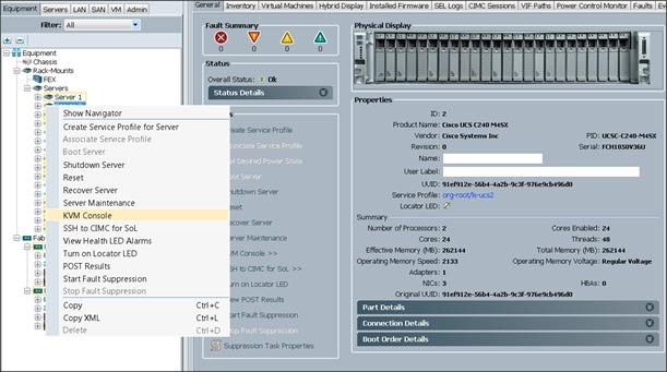
6. Click the Activate Virtual Devices found in the Virtual Media tab.
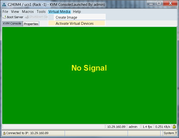
7. Click the Activate Virtual Devices found in Virtual Media tab.
8. In the KVM window, select the Virtual Media tab and click the Map CD/DVD.
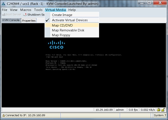
9. Browse to the Red Hat Enterprise Linux Server 6.5 installer ISO image file.
![]() The Red Hat Enterprise Linux 6.5 DVD is assumed to be on the client machine.
The Red Hat Enterprise Linux 6.5 DVD is assumed to be on the client machine.
10. Click Open to add the image to the list of virtual media.
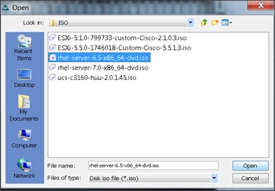
11. In the KVM window, select the KVM tab to monitor during boot.
12. In the KVM window, select the Macros > Static Macros > Ctrl-Alt-Del button in the upper left corner.
13. Click OK.
14. Click OK to reboot the system.
15. On reboot, the machine detects the presence of the Red Hat Enterprise Linux Server 6.5 install media.
16. Select the Install or Upgrade an Existing System.
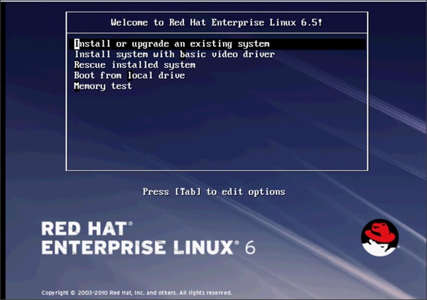
17. Skip the Media test and start the installation.
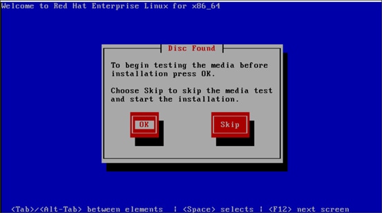
18. Click Next.
19. Select language of installation and click Next.
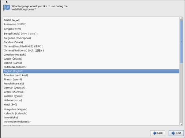
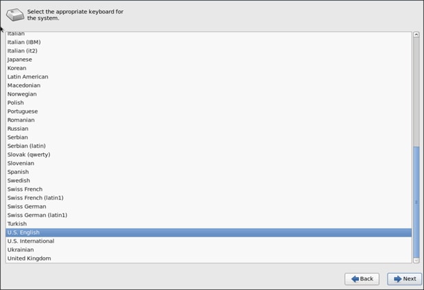
20. Select keyboard for the installation.
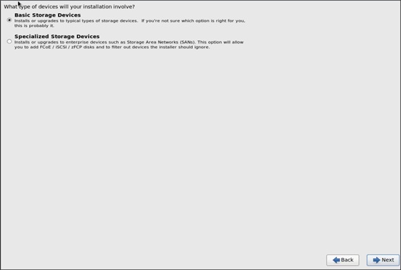
21. Select Basic Storage Devices and click Next.
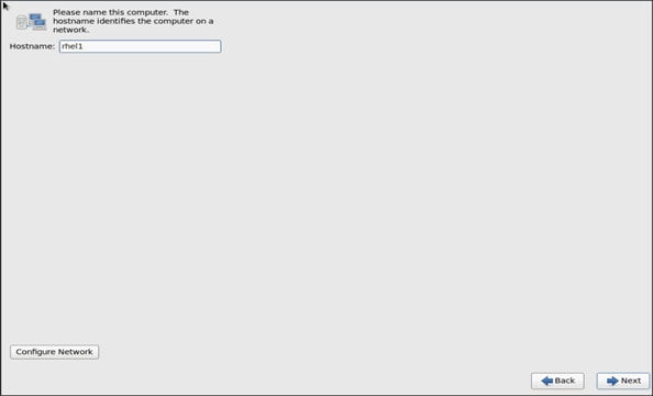
22. Provide the Hostname.
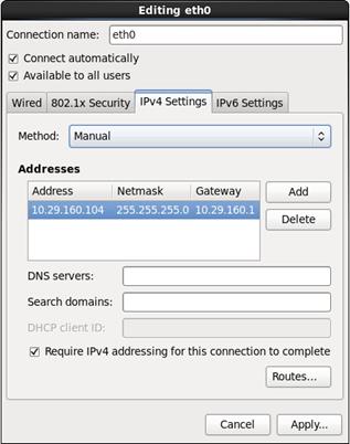
23. Configure Networking for the Host.
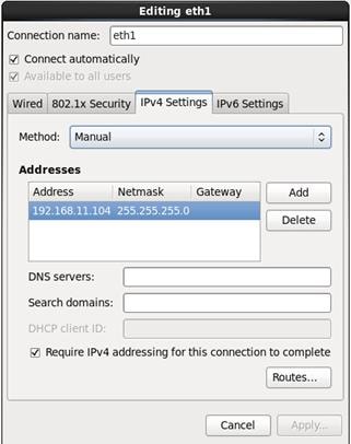
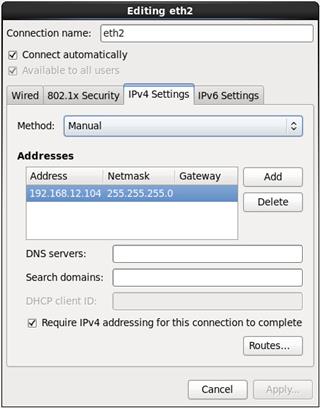
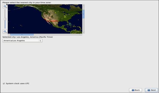
24. Select the appropriate Time Zone.
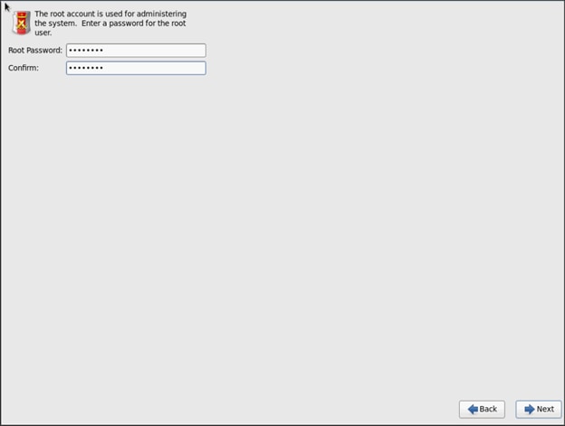
25. Select the root password.
![]() Configuring Disk Drives for Operating System on Data Nodes is accomplished through Redhat Linux Operating System (software RAID), and Configuration of disk drives for data is done using StorCli Command after installing OS, as described in section Configuring Data Drives for Datanode later in this document.
Configuring Disk Drives for Operating System on Data Nodes is accomplished through Redhat Linux Operating System (software RAID), and Configuration of disk drives for data is done using StorCli Command after installing OS, as described in section Configuring Data Drives for Datanode later in this document.
26. Choose Create custom layout for the Installation type.
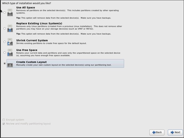
To create two software RAID 1 partitions for boot and / (root) partitions, complete the following steps:
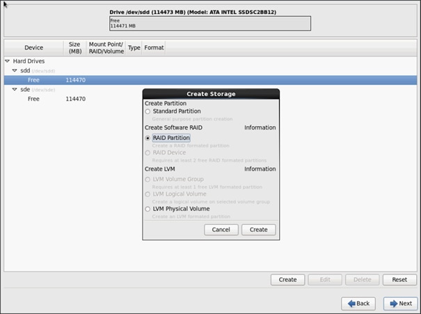
27. Choose free volume and click Create, then choose RAID Partition.
![]() The figure below shows a 120 GB hard drive in the partition. Optionally, a 480 GB hard drive can be used where we show using the 120 GB here.
The figure below shows a 120 GB hard drive in the partition. Optionally, a 480 GB hard drive can be used where we show using the 120 GB here.
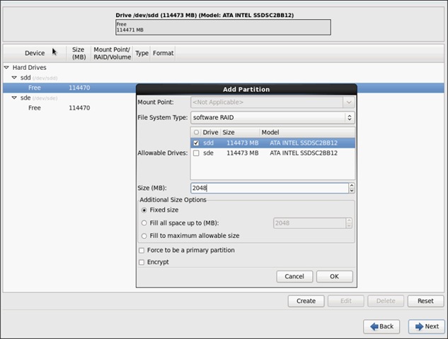
28. Choose “Software RAID” for File system Type and set size for Boot volume.
29. Do the same steps for the other free volume.
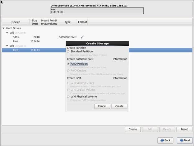
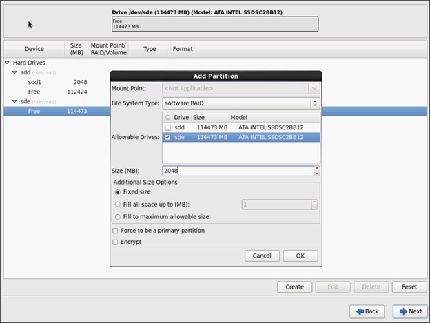
Create RAID partitions for root (/) partition on both the devices and use the rest of the available space.
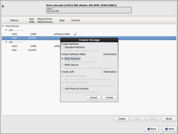
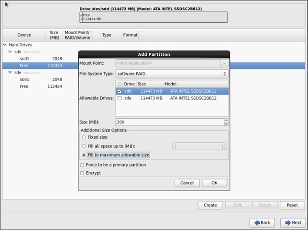
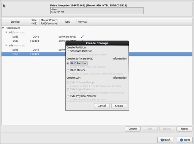
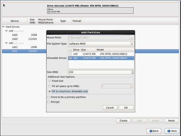
30. The above steps created 2 boot and 2 root (/) partitions.
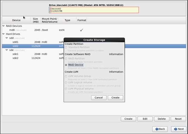
To create RAID1 Devices, complete the following steps:
1. Choose one of the boot partitions and click on Create > RAID Device.
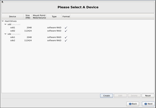
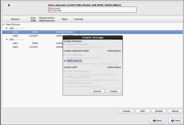
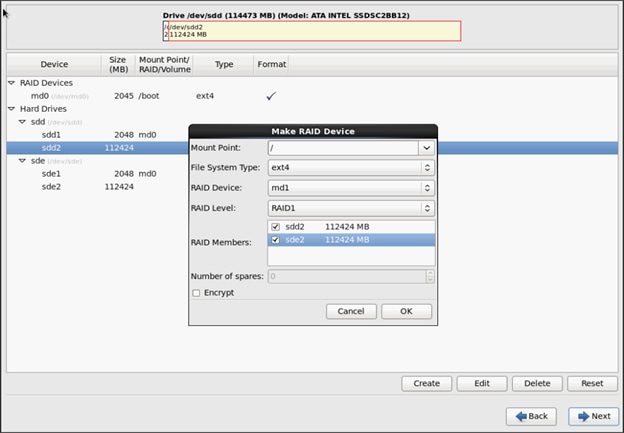
2. Choose this as /boot (boot device) and in RAID members, choose all the boot partitions created above in order to create a software RAID 1 for boot.
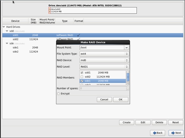
3. Similarly repeat for / partitions created above choosing both members with mount point as “/”.
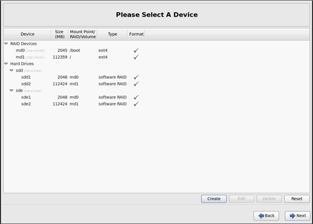
4. Click Next.
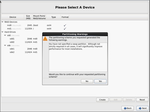
![]() Swap partition can be created using the similar steps, however, since these systems are high in memory, this step is skipped (click Yes).
Swap partition can be created using the similar steps, however, since these systems are high in memory, this step is skipped (click Yes).
5. Click Next and Format.
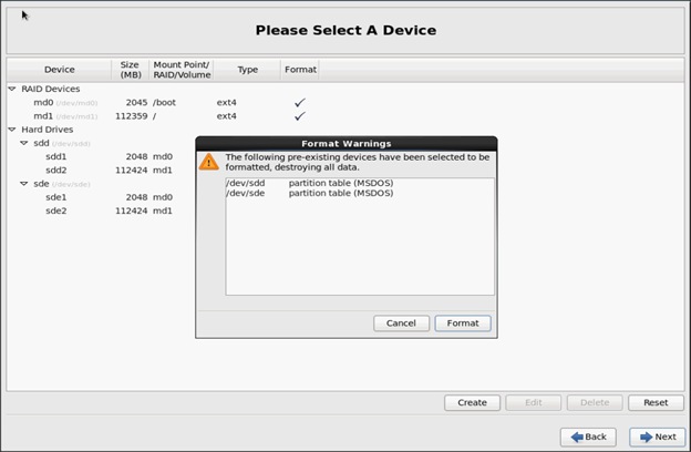
6. Select default settings and click Next.
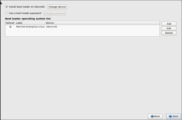
7. Continue with RHEL Installation as shown below.
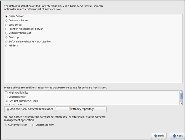
8. When the installation is complete reboot the system.
9. Repeat the steps 1 to 38 to install Red Hat Enterprise Linux 6.5 on Servers 5 through Server 67.
![]() The OS installation and configuration of the nodes that is mentioned above can be automated through PXE boot or third party tools.
The OS installation and configuration of the nodes that is mentioned above can be automated through PXE boot or third party tools.
The hostnames and their corresponding IP addresses are shown in Table 3 above.
Post OS Install Configuration
Choose one of the nodes of the cluster or a separate node as Admin Node for management such as InfoSphere BigInsights installation, cluster shell (a cluster wide parallel shell), creating a local Red Hat repo and others. In this document, we use rhel1 for this suppose.
Setup ClusterShell
ClusterShell (or clush) is a cluster wide shell that runs commands on several hosts in parallel.
1. From the system connected to the Internet download Cluster shell (clush) and install it on rhel1. Cluster shell is available from EPEL (Extra Packages for Enterprise Linux) repository.
wget http://dl.fedoraproject.org/pub/epel/6/x86_64/clustershell-1.6-1.el6.noarch.rpm
scp clustershell-1.6-1.el6.noarch.rpm rhel1:/root/
2. Login to rhel1 and install cluster shell.
yum –y install clustershell-1.6-1.el6.noarch.rpm
3. Edit the /etc/clustershell/groups file to include hostnames for all the nodes of the cluster. This set of hosts is taken when running clush with ‘-a’ option.
4. For 67 node cluster as in our CVD, set groups file as follows:
vi /etc/clustershell/groups
all: rhel[1-67].mgmt
![]() For more information and documentation on ClusterShell, visit https://github.com/cea-hpc/clustershell/wiki/UserAndProgrammingGuide.
For more information and documentation on ClusterShell, visit https://github.com/cea-hpc/clustershell/wiki/UserAndProgrammingGuide.
![]() Clustershell will not work if we have not ssh to the machine earlier (as it requires entry to be in known_hosts file), for instance, as in the case below for rhel<host> and rhel<host>.mgmt.
Clustershell will not work if we have not ssh to the machine earlier (as it requires entry to be in known_hosts file), for instance, as in the case below for rhel<host> and rhel<host>.mgmt.


Setting Up Password-less Login
To manage all of the clusters nodes from the admin node we need to setup password-less login. It assists in automating common tasks with clustershell (clush, a cluster wide parallel shell), and shell-scripts without having to use passwords.
Once Red Hat Linux is installed across all the nodes in the cluster, in order to enable password-less login across all the nodes, complete the following steps:
1. Login to the Admin Node (rhel1).
ssh 10.29.160.101
2. Run the ssh-keygen command to create both public and private keys on the admin node.
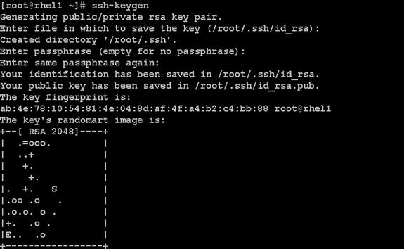
3. Then run the following command from the admin node to copy the public key id_rsa.pub to all the nodes of the cluster. ssh-copy-id appends the keys to the remote-host’s .
ssh/authorized_key.
for IP in {101..167}; do echo -n "$IP -> "; ssh-copy-id -i ~/.ssh/id_rsa.pub 10.29.160.$IP; done
4. Enter yes for Are you sure you want to continue connecting (yes/no)?
5. Enter the password of the remote host.
6. Repeat the same for user 'biadmin' since it is recommended for BI v3, a non-root user is used for installation and configuration.
7. On every node in your cluster, run the following command as both the biadmin user and root user. Select the default file storage location and leave the password blank.
ssh-keygen -t rsa
8. On the master node, run the following command as both the biadmin user and the root user to each node, and then from each node back to the master.
ssh-copy-id -i ~/.ssh/id_rsa.pub user@server_name
9. Ensure that you can log in to the remote server without a password.
ssh biadmin@server_name.com
Configuring /etc/hosts on the Admin Node
To create the host file across all the nodes in the cluster, complete the following steps:
1. Populate the host file with IP addresses and corresponding hostnames on the Admin node (rhel1).
vi/etc/hosts
127.0.0.1 localhost localhost.localdomain localhost4 localhost4.localdomain4
::1 localhost localhost.localdomain localhost6 localhost6.localdomain6
192.168.11.101 rhel1.cisco.com rhel1
192.168.11.102 rhel2.cisco.com rhel2
192.168.11.103 rhel3.cisco.com rhel3
192.168.11.104 rhel4.cisco.com rhel4
192.168.11.105 rhel5.cisco.com rhel5
192.168.11.106 rhel6.cisco.com rhel6
192.168.11.107 rhel7.cisco.com rhel7
192.168.11.108 rhel8.cisco.com rhel8
192.168.11.109 rhel9.cisco.com rhel9
192.168.11.110 rhel10.cisco.com rhel10
192.168.11.111 rhel11.cisco.com rhel11
192.168.11.112 rhel12.cisco.com rhel12
192.168.11.113 rhel13.cisco.com rhel13
192.168.11.114 rhel14.cisco.com rhel14
192.168.11.115 rhel15.cisco.com rhel15
192.168.11.116 rhel16.cisco.com rhel16
...
192.168.11.167 rhel67.cisco.com rhel67
192.168.12.101 rhel1-2.cisco.com rhel1-2
192.168.12.102 rhel2-2.cisco.com rhel2-2
192.168.12.103 rhel3-2.cisco.com rhel3-2
192.168.12.104 rhel4-2.cisco.com rhel4-2
192.168.12.105 rhel5-2.cisco.com rhel5-2
192.168.12.106 rhel6-2.cisco.com rhel6-2
192.168.12.107 rhel7-2.cisco.com rhel7-2
192.168.12.108 rhel8-2.cisco.com rhel8-2
192.168.12.109 rhel9-2.cisco.com rhel9-2
192.168.12.110 rhel10-2.cisco.com rhel10-2
192.168.12.111 rhel11-2.cisco.com rhel11-2
192.168.12.112 rhel12-2.cisco.com rhel12-2
192.168.12.113 rhel13-2.cisco.com rhel13-2
192.168.12.114 rhel14-2.cisco.com rhel14-2
192.168.12.115 rhel15-2.cisco.com rhel15-2
192.168.12.116 rhel16-2.cisco.com rhel16-2
...
192.168.12.167 rhel67-2.cisco.com rhel67-2
10.29.160.101 rhel1.mgmt
10.29.160.102 rhel2.mgmt
10.29.160.103 rhel3.mgmt
10.29.160.104 rhel4.mgmt
10.29.160.105 rhel5.mgmt
10.29.160.106 rhel6.mgmt
10.29.160.107 rhel7.mgmt
10.29.160.108 rhel8.mgmt
10.29.160.109 rhel9.mgmt
10.29.160.110 rhel10.mgmt
10.29.160.111 rhel11.mgmt
10.29.160.112 rhel12.mgmt
10.29.160.113 rhel13.mgmt
10.29.160.114 rhel14.mgmt
10.29.160.115 rhel15.mgmt
10.29.160.116 rhel16.mgmt
Configure /etc/hosts Files on All Nodes
Run the following command on the admin node (rhel1) to copy previously configured /etc/hosts file to all nodes.
clush –a –c /etc/hosts
Configuring DNS
This section details setting up DNS using dnsmasq as an example based on the /etc/hosts configuration setup in the earlier section.
To create the host file across all the nodes in the cluster, complete the following steps:
1. Disable Network manager on all nodes.
clush -a -b service NetworkManager stop
clush -a -b chkconfig NetworkManager off
2. Update /etc/resolv.conf file to point to Admin Node.
vi /etc/resolv.conf
nameserver 192.168.11.101
![]() This step is needed if setting up dnsmasq on Admin node. Otherwise, sthis file should be updated with the correct nameserver.
This step is needed if setting up dnsmasq on Admin node. Otherwise, sthis file should be updated with the correct nameserver.
3. Install and Start dnsmasq on Admin node
yum -y install dnsmasq
service dnsmasq start
chkconfig dnsmasq on
4. Deploy /etc/resolv.conf from the admin node (rhel1) to all the nodes via the following clush command:
clush -a -B -c /etc/resolv.conf
![]() A clush copy without -–dest copies to the same directory location as the source-file directory
A clush copy without -–dest copies to the same directory location as the source-file directory
5. Ensure DNS is working fine by running the following command on Admin node and any data-node.
[root@rhel2 ~]# nslookup rhel1
Server:192.168.11.101
Address:192.168.11.101#53
Name: rhel1
Address: 192.168.11.101 ç
[root@rhel2 ~]# nslookup rhel1.mgmt
Server:192.168.11.101
Address:192.168.11.101#53
Name: rhel1.mgmt
Address: 10.29.160.101 ç
[root@rhel2 ~]# nslookup 10.29.160.101
Server:192.168.11.101
Address:192.168.11.101#53
101.160.29.10.in-addr.arpa name = rhel1.mgmt. ç
Creating Red Hat Enterprise Linux (RHEL) 6.5 Local Repo
To create a repository using RHEL DVD or ISO on the admin node (in this deployment rhel1 is used for this purpose), create a directory with all the required RPMs, run the createrepo command and then publish the resulting repository.
1. Log on to rhel1. Create a directory that would contain the repository.
mkdir -p /var/www/html/rhelrepo
2. Copy the contents of the Red Hat DVD to /var/www/html/rhelrepo
3. Alternatively, if you have access to a Red Hat ISO Image, Copy the ISO file to rhel1.
scp rhel-server-6.5-x86_64-dvd.iso rhel1:/root/
Here we assume you have the Red Hat ISO file located in your present working directory.
mkdir -p /mnt/rheliso
mount -t iso9660 -o loop /root/rhel-server-6.5-x86_64-dvd.iso /mnt/rheliso/
4. Next, copy the contents of the ISO to the /var/www/html/rhelrepo directory.
cp -r /mnt/rheliso/* /var/www/html/rhelrepo

5. Now on rhel1 create a .repo file to enable the use of the yum command.
vi /var/www/html/rhelrepo/rheliso.repo
[rhel6.5]
name=Red Hat Enterprise Linux 6.5
baseurl=http://10.29.160.101/rhelrepo
gpgcheck=0
enabled=1
6. Now copy rheliso.repo file from /var/www/html/rhelrepo to /etc/yum.repos.d on rhel1
cp /var/www/html/rhelrepo/rheliso.repo /etc/yum.repos.d/
![]() Based on this repo file yum requires httpd to be running on rhel1 for other nodes to access the repository.
Based on this repo file yum requires httpd to be running on rhel1 for other nodes to access the repository.
7. Copy the rheliso.repo to all the nodes of the cluster.
clush -a -b -c /etc/yum.repos.d/rheliso.repo --dest=/etc/yum.repos.d/
![]()
8. To make use of repository files on rhel1 without httpd, edit the baseurl of repo file /etc/yum.repos.d/rheliso.repo to point repository location in the file system.
![]() This step is needed to install software on Admin Node (rhel1) using the repo (such as httpd, createrepo, etc.).
This step is needed to install software on Admin Node (rhel1) using the repo (such as httpd, createrepo, etc.).
vi /etc/yum.repos.d/rheliso.repo
[rhel6.5]
name=Red Hat Enterprise Linux 6.5
baseurl=file:///var/www/html/rhelrepo
gpgcheck=0
enabled=1
Creating the Red Hat Repository Database
1. Install the createrepo package on admin node (rhel1). Use it to regenerate the repository database(s) for the local copy of the RHEL DVD contents.
yum -y install createrepo

2. Run createrepo on the RHEL repository to create the repo database on admin node
cd /var/www/html/rhelrepo
createrepo
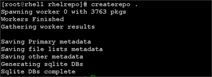
3. Finally, purge the yum caches after httpd is installed (steps in section “Install Httpd”)
Installing httpd
Setting up RHEL repo on the admin node requires httpd.
To set up RHEL repository on the admin node, complete the following steps:
1. Install httpd on the admin node to host repositories.
The Red Hat repository is hosted using HTTP on the admin node, this machine is accessible by all the hosts in the cluster.
yum –y install httpd
2. Add ServerName and make the necessary changes to the server configuration file.
vi /etc/httpd/conf/httpd.conf
ServerName 10.29.160.101:80

3. Start httpd.
service httpd start
chkconfig httpd on
4. Purge the yum caches after httpd is installed (step followed from section Setup Red Hat Repo).
clush -a -B yum clean all
clush –a –B yum repolist

![]() While suggested configuration is to disable SELinux as shown below, if for any reason SELinux needs to be enabled on the cluster, then ensure to run the following to make sure that the httpd is able to read the Yum repofiles.
While suggested configuration is to disable SELinux as shown below, if for any reason SELinux needs to be enabled on the cluster, then ensure to run the following to make sure that the httpd is able to read the Yum repofiles.
Upgrading Cisco Network Driver for VIC1227
The latest Cisco Network driver is required for performance and updates. The latest drivers can be downloaded from the link below:
1. In the ISO image, the required driver kmod-enic-2.1.1.66-rhel6u5.el6.x86_64.rpm can be located at \Linux\Network\Cisco\12x5x\RHEL\RHEL6.5
2. From a node connected to the Internet, download, extract and transfer kmod-enic-2.1.1.66-rhel6u5.el6.x86_64.rpm to rhel1 (admin node).
3. Install the rpm on all nodes of the cluster using the following clush commands. For this example the rpm is assumed to be in present working directory of rhel1.
[root@rhel1 ~]# clush -a -b -c kmod-enic-2.1.1.66-rhel6u5.el6.x86_64.rpm
[root@rhel1 ~]# clush -a -b "rpm -ivh kmod-enic-2.1.1.66-rhel6u5.el6.x86_64.rpm "
4. Ensure that the above installed version of kmod-enic driver is being used on all nodes by running the command “modinfo enic” on all nodes.
[root@rhel1 ~]# clush -a -B "modinfo enic | head -5"

NTP Configuration
The Network Time Protocol (NTP) is used to synchronize the time of all the nodes within the cluster. The Network Time Protocol daemon (ntpd) sets and maintains the system time of day in synchronism with the timeserver located in the admin node (rhel1). Configuring NTP is critical for any Hadoop Cluster. If server clocks in the cluster drift out of sync, serious problems will occur with HBase and other services.
![]() Installing an internal NTP server keeps your cluster synchronized even when an outside NTP server is inaccessible.
Installing an internal NTP server keeps your cluster synchronized even when an outside NTP server is inaccessible.
1. Configure /etc/ntp.conf on the admin node with the following contents:
vi /etc/ntp.conf
driftfile /var/lib/ntp/drift
restrict 127.0.0.1
restrict -6 ::1
server 127.127.1.0
fudge 127.127.1.0 stratum 10
includefile /etc/ntp/crypto/pw
keys /etc/ntp/keys
2. Create /root/ntp.conf on the admin node and copy it to all nodes.
vi /root/ntp.conf
server 10.29.160.101
driftfile /var/lib/ntp/drift
restrict 127.0.0.1
restrict -6 ::1
includefile /etc/ntp/crypto/pw
keys /etc/ntp/keys
3. Copy ntp.conf file from the admin node to /etc of all the nodes by executing the following command in the admin node (rhel1).
for SERVER in {102..168}; do scp /root/ntp.conf 10.29.160.$SERVER:/etc/ntp.conf; done
![]()

![]() Instead of the above for loop, this could be run as a clush command with “–w” option.
Instead of the above for loop, this could be run as a clush command with “–w” option.
clush -w rhel[2-68.
service ntpd start].mgmt –b –c /root/ntp.conf --dest=/etc
![]() Do not use the clush –a –b –c /root/ntp.conf --dest=/etc command as it overwrites /etc/ntp.conf on the admin node.
Do not use the clush –a –b –c /root/ntp.conf --dest=/etc command as it overwrites /etc/ntp.conf on the admin node.
4. Run the following to syncronize the time and restart NTP daemon on all nodes
clush -a -B "yum install -y ntpdate"
clush -a -b "ntpdate rhel1"
[root@rhel2 etc]# clush -a -b "service ntpd force-reload"
---------------
rhel[2-20] (19)
---------------
Shutting down ntpd: [ OK ]
Starting ntpd: [ OK ]
5. Ensure restart of NTP daemon across reboots.
clush -a -b "chkconfig ntpd on"
Enabling Syslog
Syslog must be enabled on each node to preserve logs regarding killed processes or failed jobs. Modern versions such as syslog-ng and rsyslog are possible, making it more difficult to be sure that a syslog daemon is present. One of the following commands should suffice to confirm that the service is properly configured:
clush -B -a rsyslogd -v
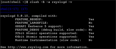
clush -B -a service rsyslog status
Setting ulimit
On each node, ulimit -n specifies the number of inodes that can be opened simultaneously. With the default value of 1024, the system appears to be out of disk space and shows no inodes available. This value should be set to 64000 on every node.
Higher values are unlikely to result in an appreciable performance gain.
1. For setting ulimit on Redhat, edit /etc/security/limits.conf on admin node rhel1 and add the following lines:
root soft nofile 64000s
root hard nofile 64000

2. If a non-root user is used to install BigInsights, please apply the following values. For example:
biadmin hard nofile 65536
biadmin soft nofile 65536
biadmin hard nproc 65536
biadmin soft nproc 65536
@biadmin hard nofile 65536
@biadmin soft nofile 65536
@biadmin hard nproc 65536
@biadmin soft nproc 65536
3. Copy the /etc/security/limits.conf file from admin node (rhel1) to all the nodes using the following command.
clush -a -b -c /etc/security/limits.conf --dest=/etc/security/
4. Edit /etc/security/limits.conf and add the following lines:
root soft nofile 64000
root hard nofile 64000
5. Check that the /etc/pam.d/su file contains the following settings:
#%PAM-1.0
auth sufficient pam_rootok.so
# Uncomment the following line to implicitly trust users in the "wheel" group.
#auth sufficient pam_wheel.so trust use_uid
# Uncomment the following line to require a user to be in the "wheel" group.
#auth required pam_wheel.so use_uid
auth include system-auth
account sufficient pam_succeed_if.so uid = 0 use_uid quiet
account include system-auth
password include system-auth
session include system-auth
session optional pam_xauth.so
6. Verify the ulimit setting with the following steps:
![]() ulimit values are applied on a new shell, running the command on a node on an earlier instance of a shell will show old values
ulimit values are applied on a new shell, running the command on a node on an earlier instance of a shell will show old values
7. Run the following command at a command line. The command should report 64000.
clush -B -a ulimit -n
Disabling SELinux
SELinux must be disabled during the install procedure and cluster setup. SELinux can be enabled after installation and while the cluster is running.
SELinux can be disabled by editing /etc/selinux/config and changing the SELINUX line to SELINUX=disabled. The following command will disable SELINUX on all nodes.
clush -a -b "sed -i 's/SELINUX=enforcing/SELINUX=disabled/g' /etc/selinux/config "
![]()
clush –a –b "setenforce 0"
![]() The above command may fail if SELinux is already disabled.
The above command may fail if SELinux is already disabled.
Set TCP Retries and Port range
Adjusting the tcp_retries parameter for the system network enables faster detection of failed nodes. Given the advanced networking features of UCS, this is a safe and recommended change (failures observed at the operating system layer are most likely serious rather than transitory). On each node, set the number of TCP retries to 5 can help detect unreachable nodes with less latency.
1. Edit the file /etc/sysctl.conf and on admin node rhel1 and add the following lines:
net.ipv4.tcp_retries2=5
net.ipv4.ip_local_port_range = 1024 64000
2. Copy the /etc/sysctl.conf file from admin node (rhel1) to all the nodes using the following command.
clush -a -b -c /etc/sysctl.conf --dest=/etc/
3. Load the settings from default sysctl file /etc/sysctl.conf by running
clush -B -a sysctl –p
Set kernel.pid_max
1. Edit the file /etc/sysctl.conf and on admin node rhel1 and add the following lines:
kernel.pid_max = 4194303
2. Copy the /etc/sysctl.conf file from admin node (rhel1) to all the nodes using the following command.
clush -a -b -c /etc/sysctl.conf --dest=/etc/
3. Load the settings from default sysctl file /etc/sysctl.conf by running
clush -B -a sysctl –p
Disabling the Linux Firewall
The default Linux firewall settings are far too restrictive for any Hadoop deployment. Since the UCS Big Data deployment will be in its own isolated network, there’s no need to leave the iptables service running.
clush -a -b "service iptables stop"
clush -a -b "chkconfig iptables off"
![]()
Disable Swapping
In order to reduce Swapping, run the following on all nodes. Variable vm.swappiness defines how often swap should be used. 0 is No Swapping, 60 default.
clush -a -b " echo 'vm.swappiness=0' >> /etc/sysctl.conf"
Load the settings from default sysctl file /etc/sysctl.conf
clush –a –b “sysctl –p”
Disable Transparent Huge Pages
Disabling Transparent Huge Pages (THP) reduces elevated CPU usage caused by THP. From the admin node, run the following commands.
clush -a -b "echo never >
/sys/kernel/mm/redhat_transparent_hugepage/enabled"
clush -a -b "echo never >
/sys/kernel/mm/redhat_transparent_hugepage/defrag"
The above command needs to be run for every reboot, hence, copy this command to /etc/rc.local so they are executed automatically for every reboot.
1. On Admin node, run the following commands:
rm –f /root/thp_disable
echo "echo never > /sys/kernel/mm/redhat_transparent_hugepage/enabled" >> /root/thp_disable
echo "echo never > /sys/kernel/mm/redhat_transparent_hugepage/defrag " >> /root/thp_disable
2. Copy file to each node.
clush –a –b –c /root/thp_disable
3. Append the content of file thp_disable to /etc/rc.local.
clush -a -b “cat /root/thp_disable >> /etc/rc.local”
Disable IPv6 Defaults
1. Disable IPv6 as the addresses used are IPv4.
clush -a -b “echo 'net.ipv6.conf.all.disable_ipv6 = 1' >> /etc/sysctl.conf”
clush -a -b “echo 'net.ipv6.conf.default.disable_ipv6 = 1' >> /etc/sysctl.conf”
clush -a -b “echo 'net.ipv6.conf.lo.disable_ipv6 = 1' >> /etc/sysctl.conf”
2. Load the settings from default sysctl file /etc/sysctl.conf
clush –a –b “sysctl –p”
Setting JAVA_HOME
1. Execute the following command on admin node (rhel1).
echo “export JAVA_HOME=/usr/lib/jvm/jre-1.7.0-openjdk.x86_64” >> /etc/profile
2. Copy the profile file from admin node (rhel1) to all the nodes using the following command.
clush -a -c /etc/profile
Configuring Data Drives on Master Nodes
This section describes steps to configure non-OS disk drives as RAID1 using StorCli command as described below. All the drives are going to be part of a single RAID1 volume. This volume can be used for staging any client data to be loaded to HDFS. This volume won’t be used for HDFS data.
Go to the website to download storcli: http://www.lsi.com/downloads/Public/RAID%20Controllers/RAID%20Controllers%20Common%20Files/1.14.12_StorCLI.zip
1. Extract the zip file and copy storcli-1.14.12-1.noarch.rpm from the linux directory.
2. Download storcli and its dependencies and transfer to Admin node.
scp storcli-1.14.12-1.noarch.rpm rhel1:/root/
3. Copy storcli rpm to all the nodes using the following commands:
clush -a -b -c /root/storcli-1.14.12-1.noarch.rpm --dest=/root/
4. Run the below command to install storcli on all the nodes.
clush -a -b rpm -ivh storcli-1.14.12-1.noarch.rpm
5. Run the following command to copy storcli64 to root directory.
cd /opt/MegaRAID/storcli/
cp storcli64 /root/

6. Copy storcli64 to all the nodes using the following commands:
clush -a -b -c /root/storcli64 --dest=/root/
7. Run the following script as root user on rhel1, rhel2 and rhel3 to create the virtual drives.
vi /root/raid1.sh
./storcli64 -cfgldadd r1[$1:1,$1:2,$1:3,$1:4,$1:5,$1:6,$1:7,$1:8,$1:9,$1:10,$1:11,$1:12,$1:13,$1:14,$1:15,$1:16,$1:17,$1:18,$1:19,$1:20,$1:21,$1:22,$1:23,$1:24] wb ra nocachedbadbbu strpsz1024 -a0
The above script requires enclosure ID as a parameter.
8. Run the following command to get enclosure id.
./storcli64 pdlist -a0 | grep Enc | grep -v 252 | awk '{print $4}' | sort | uniq -c | awk '{print $2}'
chmod 755 raid1.sh
9. Run the MegaCli script as follows:
./raid1.sh <EnclosureID> obtained by running the command above
WB: Write back
RA: Read Ahead
NoCachedBadBBU: Do not write cache when the BBU is bad.
Strpsz1024: Strip Size of 1024K
![]() The command above will not override any existing configuration. To clear and reconfigure existing configurations refer to Embedded MegaRAID Software Users Guide available at www.lsi.com.
The command above will not override any existing configuration. To clear and reconfigure existing configurations refer to Embedded MegaRAID Software Users Guide available at www.lsi.com.
Configuring Data Drives on Data Nodes
This section describes steps to configure non-OS disk drives as individual RAID0 volumes using StorCli command as described below. These volumes are going to be used for HDFS Data.
Issue the following command from the admin node to create the virtual drives with individual RAID 0 configurations on all the datanodes.
clush –w rhel[4-67] -B ./storcli64 -cfgeachdskraid0 WB RA direct NoCachedBadBBU strpsz1024 -a0
WB: Write back
RA: Read Ahead
NoCachedBadBBU: Do not write cache when the BBU is bad.
Strpsz1024: Strip Size of 1024K
![]() The command above will not override existing configurations. To clear and reconfigure existing configurations refer to Embedded MegaRAID Software Users Guide available at www.lsi.com.
The command above will not override existing configurations. To clear and reconfigure existing configurations refer to Embedded MegaRAID Software Users Guide available at www.lsi.com.
Configuring the Filesystem on all nodes
The following script will format and mount the available volumes on each node whether it is Master node or Data node. OS boot partition is going to be skipped. All drives are going to be mounted based on their UUID as /data/disk1, /data/disk2, and so on.
1. On the Admin node, create a file containing the following script.
To create partition tables and file systems on the local disks supplied to each of the nodes, run the following script as the root user on each node.
![]() The script assumes there are no partitions already existing on the data volumes. If there are partitions, then they have to be deleted first before running this script. This process is documented in the “Note” section at the end of the section.
The script assumes there are no partitions already existing on the data volumes. If there are partitions, then they have to be deleted first before running this script. This process is documented in the “Note” section at the end of the section.
vi /root/driveconf.sh
#!/bin/bash
#Commented because the script intermittently fails on some occasions
[[ "-x" == "${1}" ]] && set -x && set -v && shift 1
count=1
for X in /sys/class/scsi_host/host?/scan
do
echo '- - -' > ${X}
done
for X in /dev/sd?
do
echo "========"
echo $X
echo "========"
if [[ -b ${X} && `/sbin/parted -s ${X} print quit|/bin/grep -c boot` -ne 0]]
then
echo "$X bootable - skipping."
continue
else
Y=${X##*/}1
echo "Formatting and Mounting Drive => ${X}"
echo "y" | mkfs.ext4 -b 4096 -O dir_index,extent ${X}
(( $? )) && continue
#Identify UUID
UUID=`blkid ${X} | cut -d " " -f2 | cut -d "=" -f2 | sed 's/"//g'`
/bin/mkdir -p /data/disk${count}
(( $? )) && continue
echo "UUID of ${X} = ${UUID}, mounting ${X} using UUID on /data/disk${count}"
mount -vs -t ext4 -o nobarrier,noatime,nodiratime,nobh,nouser_xattr,data=writeback,commit=100 -U ${UUID} /data/disk${count}
(( $? )) && continue
echo "UUID=${UUID} /data/disk${count} ext4 nobarrier,noatime,nodiratime,nobh,nouser_xattr,data=writeback,commit=100 0 0" >> /etc/fstab
((count++))
fi
done
2. Run the following command to copy driveconf.sh to all the nodes.
chmod 755 /root/driveconf.sh
clush –a -B –c /root/driveconf.sh
3. Run the following command from the admin node to run the script across all data nodes.
clush –a –B /root/driveconf.sh
4. Run the following from the admin node to list the partitions and mount points.
clush –a -B df –h
clush –a -B mount
clush –a -B cat /etc/fstab
![]() In-case there is need to delete any partitions, it can be done so using the following.
In-case there is need to delete any partitions, it can be done so using the following.
5. Run command ‘mount’ to identify which drive is mounted to which device /dev/sd<?>
umount the drive for which partition is to be deleted and run fdisk to delete as shown below.
Care to be taken not to delete the OS partition as this will wipe out the OS.
mount
umount /data/disk1 # disk1 shown as example
(echo d; echo w;) | sudo fdisk /dev/sd<?>
Cluster Verification
The section describes the steps to create the script cluster_verification.sh that helps to verify CPU, memory, NIC, storage adapter settings across the cluster on all nodes. This script also checks additional prerequisites such as NTP status, SELinux status, ulimit settings, JAVA_HOME settings and JDK version, IP address and hostname resolution, Linux version and firewall settings.
1. Create the cluster_verification.sh script on the Admin node (rhel1):
vi cluster_verification.sh
#!/bin/bash
shopt -s expand_aliases
# Setting Color codes
green='\e[0;32m'
red='\e[0;31m'
NC='\e[0m' # No Color
echo -e "${green} === Cisco UCS Integrated Infrastructure for Big Data \ Cluster Verification === ${NC}"
echo ""
echo ""
echo -e "${green} ==== System Information ==== ${NC}"
echo ""
echo ""
echo -e "${green}System ${NC}"
clush -a -B " `which dmidecode` |grep -A2 '^System Information'"
echo ""
echo ""
echo -e "${green}BIOS ${NC}"
clush -a -B " `which dmidecode` | grep -A3 '^BIOS I'"
echo ""
echo ""
echo -e "${green}Memory ${NC}"
clush -a -B "cat /proc/meminfo | grep -i ^memt | uniq"
echo ""
echo ""
echo -e "${green}Number of Dimms ${NC}"
clush -a -B "echo -n 'DIMM slots: '; `which dmidecode` |grep -c \ '^[[:space:]]*Locator:'"
clush -a -B "echo -n 'DIMM count is: '; `which dmidecode` | grep \ "Size"| grep -c "MB""
clush -a -B " `which dmidecode` | awk '/Memory Device$/,/^$/ {print}' |\ grep -e '^Mem' -e Size: -e Speed: -e Part | sort -u | grep -v -e 'NO \ DIMM' -e 'No Module Installed' -e Unknown"
echo ""
echo ""
# probe for cpu info #
echo -e "${green}CPU ${NC}"
clush -a -B "grep '^model name' /proc/cpuinfo | sort -u"
echo ""
clush -a -B "`which lscpu` | grep -v -e op-mode -e ^Vendor -e family -e\ Model: -e Stepping: -e BogoMIPS -e Virtual -e ^Byte -e '^NUMA node(s)'"
echo ""
echo ""
# probe for nic info #
echo -e "${green}NIC ${NC}"
clush -a -B "`which ifconfig` | egrep '(^e|^p)' | awk '{print \$1}' | \ xargs -l `which ethtool` | grep -e ^Settings -e Speed"
echo ""
clush -a -B "`which lspci` | grep -i ether"
echo ""
echo ""
# probe for disk info #
echo -e "${green}Storage ${NC}"
clush -a -B "echo 'Storage Controller: '; `which lspci` | grep -i -e \ raid -e storage -e lsi"
echo ""
clush -a -B "dmesg | grep -i raid | grep -i scsi"
echo ""
clush -a -B "lsblk -id | awk '{print \$1,\$4}'|sort | nl"
echo ""
echo ""
echo -e "${green} ================ Software ======================= ${NC}"
echo ""
echo ""
echo -e "${green}Linux Release ${NC}"
clush -a -B "cat /etc/*release | uniq"
echo ""
echo ""
echo -e "${green}Linux Version ${NC}"
clush -a -B "uname -srvm | fmt"
echo ""
echo ""
echo -e "${green}Date ${NC}"
clush -a -B date
echo ""
echo ""
echo -e "${green}NTP Status ${NC}"
clush -a -B "ntpstat 2>&1 | head -1"
echo ""
echo ""
echo -e "${green}SELINUX ${NC}"
clush -a -B "echo -n 'SElinux status: '; grep ^SELINUX= \ /etc/selinux/config 2>&1"
echo ""
echo ""
echo -e "${green}IPTables ${NC}"
clush -a -B "`which chkconfig` --list iptables 2>&1"
echo ""
clush -a -B " `which service` iptables status 2>&1 | head -10"
echo ""
echo ""
echo -e "${green}CPU Speed${NC}"
clush -a -B "echo -n 'CPUspeed Service: '; `which service` cpuspeed \ status 2>&1"
clush -a -B "echo -n 'CPUspeed Service: '; `which chkconfig` --list \ cpuspeed 2>&1"
echo ""
echo ""
echo -e "${green}Java Version${NC}"
clush -a -B 'java -version 2>&1; echo JAVA_HOME is ${JAVA_HOME:-Not \ Defined!}'
echo ""
echo ""
echo -e "${green}Hostname Lookup${NC}"
clush -a -B " ip addr show"
echo ""
echo ""
echo -e "${green}Open File Limit${NC}"
clush -a -B 'echo -n "Open file limit(should be >32K): "; ulimit -n'
2. Change permissions to executable:
chmod 755 cluster_verification.sh
3. Run the Cluster Verification tool from the admin node. This can be run before starting Hadoop to identify any discrepancies in Post OS Configuration between the servers or during troubleshooting of any cluster / Hadoop issues.
./cluster_verification.sh
Installing IBM BigInsights for Apache Hadoop using the Graphical User Interface (GUI)
BigInsights provides a web-based GUI that installs and configures selected features and also displays the details of the progress of the installation. This console can be used to start and stop components, add or remove nodes, track MapReduce jobs statuses, analyze log records and the overall system health, view the contents of the distributed file system etc.
Download and Install BigInsights
From a host connected to the Internet, using a web browser, download the InfoSphere BigInsights installation files (iibi30_eval_x86_64.tar.gz) from the IBM website and transfer it to the admin node.
1. Transfer InfoSphere BigInsights files to rhel1
[root@jb ~]# scp iibi30_eval_x86_64.tar.gz rhel1:/home/
[root@rhel1 home]# tar -xvzf iibi30_eval_x86_64.tar.gz
2. Create user biadmin
[root@rhel1 ~]# clush -a -B "groupadd -g 123 biadmin"
[root@rhel1 ~]# clush -a -B "useradd –g biadmin -u 123 biadmin
[root@rhel1 ~]# clush -a -B "echo biadminpassw0rd | passwd biadmin --stdin"
![]() Password used for user biadmin is “biadminpassw0rd”
Password used for user biadmin is “biadminpassw0rd”
3. Add biadmin in /etc/sudoers on all the nodes.
[root@rhel1 ~]# clush -a "echo \"biadmin ALL=(ALL) NOPASSWD:ALL \" >> /etc/sudoers"
[root@rhel1 ~]# clush -a "echo \"%biadmin ALL=(ALL) NOPASSWD:ALL
\" >> /etc/sudoers"
4. On the rhel1 /etc/sudoers file. Comment out the following line.
Defaults requiretty
5. Add MaxStartups in sshd config file on all nodes.
[root@rhel1 ~]# echo "MaxStartups 50" >> /etc/ssh/sshd_config
[root@rhel1 ~]# clush -a -b -c /etc/ssh/sshd_config
6. Create directories for the data files and cache files for the distributed file system.
a. On all nodes create hdfs and mapred directories (only disk1).
[root@rhel1 ~]# clush –a “mkdir -p /data/disk1/hadoop/hdfs”
[root@rhel1 ~]# clush –a “mkdir -p /data/disk1/hadoop/mapred”
b. On non-maser nodes create hdfs and mapred directories (disk1 through disk12)
[root@rhel1 ~]# clush –w rhel[4-67] “mkdir -p /data/disk1/hadoop/hdfs”
..
[root@rhel1 ~]# clush –w rhel[4-67] “mkdir -p /data/disk12/hadoop/hdfs”
[root@rhel1 ~]# clush –w rhel[4-67] “mkdir -p /data/disk1/hadoop/mapred”
..
[root@rhel1 ~]# clush –w rhel[4-67] “mkdir -p /data/disk12/hadoop/mapred”
7. Make biadmin the owner of data directories.
[root@rhel1 ~]# clush -a "chown –R biadmin:biadmin /data/*"
8. Install expect numactl and ksh (if not already installed).
[root@rhel1 ~]# clush -a -B "yum -y install expect numactl ksh"
![]() If you get the following error: Installed size: 6.6 M
If you get the following error: Installed size: 6.6 M
Downloading Packages: http://9.30.75.202/rhelrepo/Packages/expect-5.44.1.15-5.el6_4.x86_64.rpm: [Error 14] PYCURL ERROR 7 - "couldn't connect to host" Trying other mirror. Start the http server: [root@rhel1 ~] service httpd start.
Add umask 022 in the root user's .bashrc file on all nodes. This makes the file permission executable by all users.ssh.
[root@rhel1 ~]# echo "umask 022" >> /root/.bashrc
[root@rhel1 ~]# clush -a –c /root/.bashrc
Start Installer Web Server
1. From the extracted biginsights directory run the start.sh script to start the installer web server.
[root@rhel1 biginsights-3.0.0.0-SNAPSHOT-enterprise-evaluation-Linux-amd64-b20140616_1652]# ./start.sh
artifacts/ibm-java-sdk-6.0-12.0-linux-x86_64.tgz
Running local precheck script
================================================
BigInsights Pre-Installation Check Script v1.2.2
================================================
Machine: rhel1
Architecture: xSeries
OS: Red Hat v6.4
================================================
[INFO] (CDYIN0017I) Running in INSTALL_PRE_UI mode.
Verify there is no install process in the background [OK]
Verify install ports not in use [OK]
Extracting Java
Java extraction complete, using JAVA_HOME=/home/biginsights-3.0.0.0-SNAPSHOT-enterprise-evaluation-Linux-amd64-b20140616_1652/_jvm/ibm-java-x86_64-60
Verifying port 8300 availability
port 8300 available
Starting BigInsights Installer
Deploying Installer EAR and WAR
Using GERONIMO_HOME: /home/biginsights-3.0.0.0-SNAPSHOT-enterprise-evaluation-Linux-amd64-b20140616_1652/installer-console
Using GERONIMO_TMPDIR: var/temp
Using JRE_HOME: /home/biginsights-3.0.0.0-SNAPSHOT-enterprise-evaluation-Linux-amd64-b20140616_1652/_jvm/ibm-java-x86_64-60/jre
Deployed BigInsights/BigInsightsInstallEAR/1.0/car
`-> BigInsightsInstall.jar
Using GERONIMO_HOME: /home/biginsights-3.0.0.0-SNAPSHOT-enterprise-evaluation-Linux-amd64-b20140616_1652/installer-console
Using GERONIMO_TMPDIR: var/temp
Using JRE_HOME: /home/biginsights-3.0.0.0-SNAPSHOT-enterprise-evaluation-Linux-amd64-b20140616_1652/_jvm/ibm-java-x86_64-60/jre
Deployed BigInsights/Installer/1.0/car @ /Install
Using GERONIMO_HOME: /home/biginsights-3.0.0. 0-SNAPSHOT-enterprise-evaluation-Linux-amd64-b2 0140616_1652/installer-console
Using GERONIMO_TMPDIR: var/temp
Using JRE_HOME: /home/biginsights-3.0.0. 0-SNAPSHOT-enterprise-evaluation-Linux-amd64-b2 0140616_1652/_jvm/ibm-java-x86_64-60/jre
Stopped
org.apache.geronimo.plugins/plugin-console- tomcat/2.1.8-wasce/car
BigInsights Installer started, please use a browser to access one of the following URL(s):
http://10.29.160.53:8300/Install
After you are finished, run the following command to stop the installer web server:
start.sh shutdown
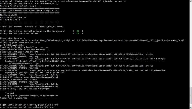
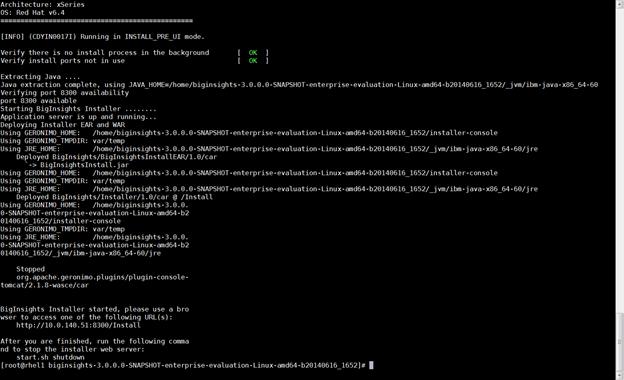
![]() The installer web server should be running throughout the installation process. Once installed, this is automatically shutdown. However if needed to shut down the installer web server manually, this can be done as shown above.
The installer web server should be running throughout the installation process. Once installed, this is automatically shutdown. However if needed to shut down the installer web server manually, this can be done as shown above.
BigInsights GUI
When the BigInsights Installer has started, access the BigInsights Install Wizard through the browser.
1. Point the browser to http://10.29.160.53:8300/Install
2. In BigInsights Welcome Panel shown below click Next.
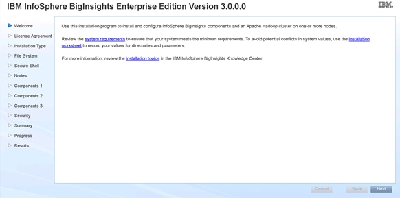
3. If acceptable to you, accept the terms of the license agreement, and click Next.
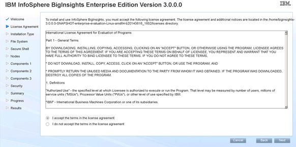
4. Check the Install InfoSphere BigInsights and click Next.
5. Enter the cluster name and other parameters as shown below.
Table 4 Directory Setup
| Directory |
Description |
| Cache directory |
Directory where the MapReduce intermediate data (map output data) is stored |
| Log directory |
Directory where MapReduce logs are written to |
| MapReduce system directory |
System directory where Hadoop stores its configuration data |
6. Set the Cache Directory to the following:
/data/disk1/hadoop/mapred/local,/data/disk2/hadoop/mapred/local,/data/disk3/hadoop/mapred/local,/data/disk4/hadoop/mapred/local,/data/disk5/hadoop/mapred/local,/data/disk6/hadoop/mapred/local,/data/disk7/hadoop/mapred/local,/data/disk8/hadoop/mapred/local,/data/disk9/hadoop/mapred/local,/data/disk10/hadoop/mapred/local,/data/disk11/hadoop/mapred/local,/data/disk12/hadoop/mapred/local
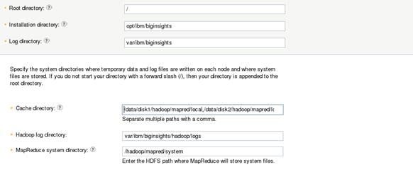
7. Select the checkbox Use the current user biadmin with sudo privileges to the current node only (enter biadmin's password) to make any necessary configuration changes.
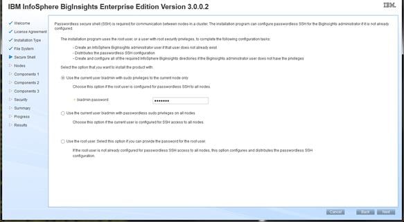
8. Click Add Nodes and enter Hostname Pattern Expression rhel[1-67].cisco.com in the Hosts field.
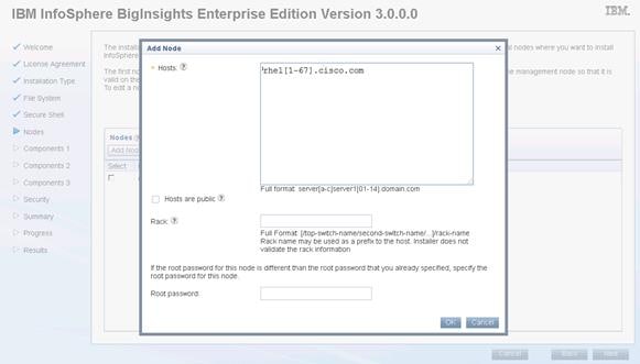
9. Make sure that Installer has located the correct hosts for the cluster and click Next.
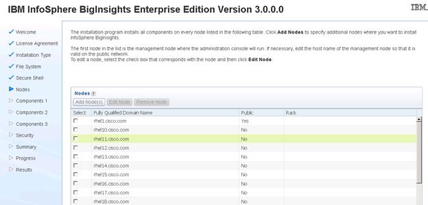
10. Enter all the parameters as shown in the figure below.
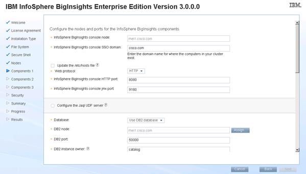
11. Enter the biadmin and DB2admin password. For this document they are biadminpassw0rd and db2passw0rd.
12. Enter the details for Big SQL as shown below. Use the following as the Big SQL data directory to spread the IO:
/data/disk1/bigsql/data,/data/disk2/bigsql/data,/data/disk3/bigsql/data,/data/disk4/bigsql/data,/data/disk5/bigsql/data,/data/disk6/bigsql/data,/data/disk7/bigsql/data,/data/disk8/bigsql/data,/data/disk9/bigsql/data,/data/disk10/bigsql/data,/data/disk11/bigsql/data,/data/disk12/bigsql/data
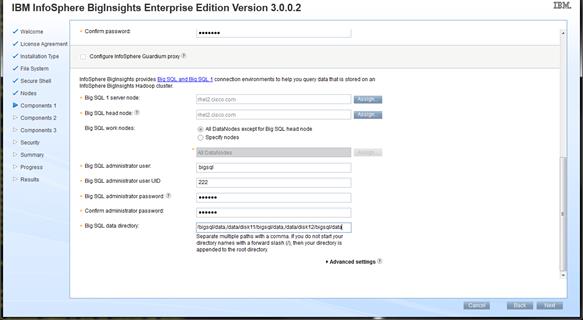
Role Assignment
The subsection deals with role assignment, port and directory details. The ports mentioned in the third column are the default ports and are mentioned for reference only.
![]() Do not change the ports listed in 0
Do not change the ports listed in 0
Table 5 Role and Port Assignments
| Service Name |
Host |
Details |
| NameNode |
rhel1 |
NameNode port: 9000 NameNode HTTP port: 50070 NameNode JMX port: 51170 Table and transaction logs directory: /data/disk1/hdfs/name,/data/disk2/hdfs/name,/data/disk3/hdfs/name,/data/disk4/hdfs/name,/data/disk5/hdfs/name,/data/disk6/hdfs/name,/data/disk7/hdfs/name,/data/disk8/hdfs/name,/data/disk9/hdfs/name,/data/disk10/hdfs/name,/data/disk11/hdfs/name,/data/disk12/hdfs/name |
| Secondary NameNode |
rhel2 |
Secondary NameNode HTTP port: 50090 Secondary NameNode data directories: /data/disk1/hdfs/datasecondary,/data/disk2/hdfs/datasecondary,/data/disk3/hdfs/datasecondary,/data/disk4/hdfs/datasecondary,/data/disk5/hdfs/datasecondary,/data/disk6/hdfs/datasecondary,/data/disk7/hdfs/datasecondary,/data/disk8/hdfs/datasecondary,/data/disk9/hdfs/datasecondary,/data/disk10/hdfs/datasecondary,/data/disk11/hdfs/datasecondary,/data/disk12/hdfs/datasecondary |
| Big SQL |
rhel2 |
|
| JobTracker |
rhel3 |
JobTracker port: 9001 JobTracker HTTP port: 50030 JobTracker JMX port: 51130 |
| DataNode and Tasktracker Nodes |
rhel[4-67] |
DataNode port: 50010 DataNode IPC port: 50020 DataNode HTTP port: 50075 DataNode JMX port: 51110 TaskTracker HTTP port: 50060 Data directory: /data/disk1/hdfs/data,/data/disk2/hdfs/data,/data/disk3/hdfs/data,/data/disk4/hdfs/data,/data/disk5/hdfs/data,/data/disk6/hdfs/data,/data/disk7/hdfs/data,/data/disk8/hdfs/data,/data/disk9/hdfs/data,/data/disk10/hdfs/data,/data/disk11/hdfs/data,/data/disk12/hdfs/data |
| HBase Master HBase Region Server |
rhel2 rhel[4-67] |
Master UI port: 60010 Region server UI port: 60030 Root directory: /hbase |
| Zookeeper |
rhel[1-3] |
ZooKeeper port: 2181 |
| Oozie Server |
rhel1 |
Oozie port: 8280 |
13. In the Namenode section. Click the Assign button and choose rhel1 from the list.
14. In the Secondary namenode section. Click the Assign button and choose rhel2 from the list.
15. For DataNode and TaskTraker nodes select the checkbox. Use all nodes except the NameNode, JobTracker, and Secondary NameNode nodes.
16. For Data directory enter:
/data/disk1/hadoop/hdfs,/data/disk2/hadoop/hdfs,/data/disk3/hadoop/hdfs,/data/disk4/hadoop/hdfs,/data/disk5/hadoop/hdfs,/data/disk6/hadoop/hdfs,/data/disk7/hadoop/hdfs,/data/disk8/hadoop/hdfs,/data/disk9/hadoop/hdfs,/data/disk10/hadoop/hdfs,/data/disk11/hadoop/hdfs,/data/disk12/hadoop/hdfs
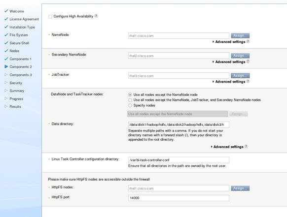
17. Verify the Advanced Settings such as ports assignment and click Next.
![]() We choose default port assignment for the purpose of this document.
We choose default port assignment for the purpose of this document.
18. In the HBase section, click Assign and choose rhel2.cisco.com as HBase master server nodes.
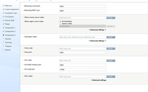
19. In the Zookeeper section, click Assign and choose rhel1, rhel2 and rhel3 as Zookeeper nodes.
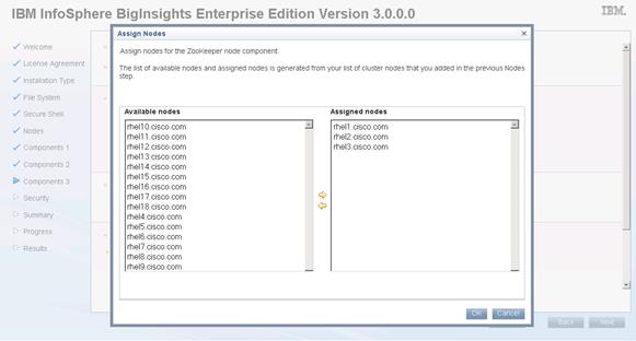
20. In the Oozie section, click Assign and choose rhel1 as Oozie node.
21. In the Alert section, click Assign and choose rhel1 as Alert node.
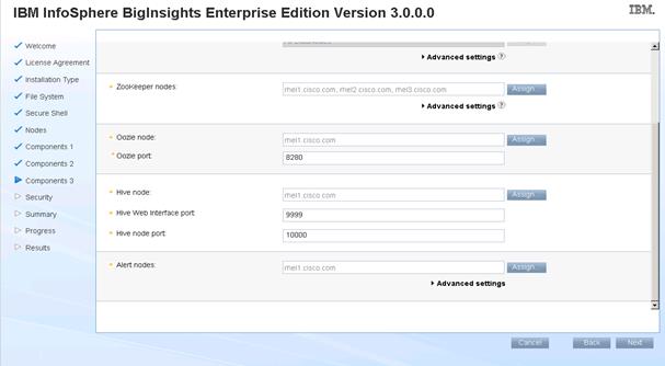
22. For security settings, Select PAM with flat file authentication (you might consider another
setting for your environment), then click Next.
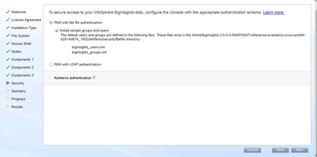
23. Review the installation settings and click Install.
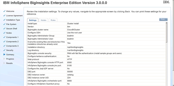
24. Biginsights Installation completed successfully. Review the details and click Finish.
BigInsights Installation web application is automatically stopped after successful installation.
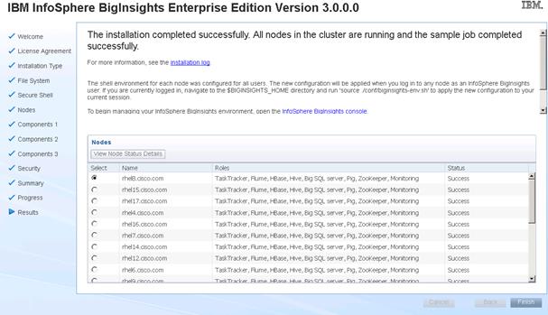
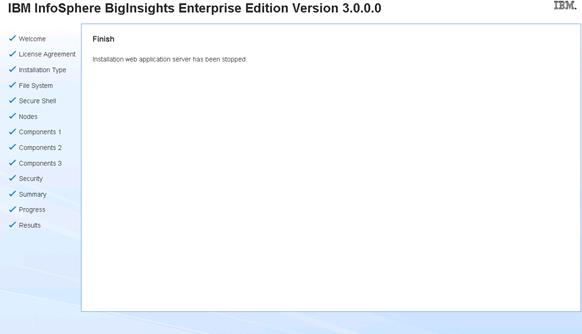
To run any application using the BigInsights, log into http://10.29.160.53:8080.
Bill of Materials
This section provides the BOM for the 67 node Performance and Capacity Balanced Cluster. See 0for BOM for the master rack, 0 for expansion racks (rack 2 to 4), 0and 0for software components.
Table 6 Bill of Materials for Base Rack
| Part Number |
||
| UCSC-C220-M4S |
UCS C220 M4 SFF w/o CPU mem HD PCIe PSU rail kit |
3 |
| UCSC-MRAID12G-2GB |
Cisco 12Gbps SAS 2GB FBWC Cache module (Raid 0/1/5/6) |
19 |
| UCSC-MLOM-CSC-02 |
Cisco UCS VIC1227 VIC MLOM - Dual Port 10Gb SFP+ |
19 |
| UCS-SD120G0KSB-EV |
120 GB 2.5 inch Enterprise Value 6G SATA SSD (BOOT) |
32 |
| UCSC-PSU1-770W |
770W AC Hot-Plug Power Supply for 1U C-Series Rack Server |
6 |
| UCSC-HS-C220M4 |
Heat Sink for UCS C220 M4 Rack Server |
6 |
| UCSC-SCCBL240 |
Supercap cable 250mm |
16 |
| A03-D600GA2 |
600GB 6Gb SAS 10K RPM SFF HDD/hot plug/drive sled mounted |
24 |
| UCS-L-6200-10G-C |
2rd Gen FI License to connect C-direct only |
68 |
| UCS-BLKE-6200 |
UCS 6200 Series Expansion Module Blank |
6 |
| UCS 6296UP Fan Module |
UCS 6296UP Fan Module |
8 |
| CAB-N5K6A-NA |
Power Cord 200/240V 6A North America |
4 |
| UCS-FI-E16UP |
UCS 6200 16-port Expansion module/16 UP/ 8p LIC |
4 |
| RACK-UCS2 |
Cisco R42610 standard rack w/side panels |
1 |
| RP208-30-1P-U-2= |
Cisco RP208-30-U-2 Single Phase PDU 20x C13 4x C19 (Country Specific) |
2 |
| CON-UCW3-RPDUX |
UC PLUS 24X7X4 Cisco RP208-30-U-X Single Phase PDU 2x (Country Specific) |
6 |
Table 7 Optional Base Rack Materials
| UCS-SD480G0KSB-EV |
480 GB 2.5 inch Enterprise Value 6G SATA SSD (BOOT) |
32 |
![]() You can use the 480 GB Boot SSD in place of the 120 GB SSDs.
You can use the 480 GB Boot SSD in place of the 120 GB SSDs.
Table 8 Bill of Material for Expansion Racks
| Part Number |
Description |
Quantity |
| UCSC-C240-M4L |
UCS C240 M4 LFF 12 HD w/o CPU mem HD PCIe PS railkt w/expdr |
48 |
| UCSC-MRAID12G |
Cisco 12G SAS Modular Raid Controller |
48 |
| UCSC-MRAID12G-2GB |
Cisco 12Gbps SAS 2GB FBWC Cache module (Raid 0/1/5/6) |
48 |
| UCSC-MLOM-CSC-02 |
Cisco UCS VIC1227 VIC MLOM - Dual Port 10Gb SFP+ |
48 |
| CAB-9K12A-NA |
Power Cord 125VAC 13A NEMA 5-15 Plug North America |
96 |
| UCSC-PSU2V2-1200W |
1200W V2 AC Power Supply for 2U C-Series Servers |
96 |
| UCSC-RAILB-M4 |
Ball Bearing Rail Kit for C220 M4 and C240 M4 rack servers |
48 |
| UCSC-HS-C240M4 |
Heat Sink for UCS C240 M4 Rack Server |
96 |
| UCSC-SCCBL240 |
Supercap cable 250mm |
48 |
| UCS-CPU-E52680D |
2.50 GHz E5-2680 v3/120W 12C/30MB Cache/DDR4 2133MHz |
96 |
| UCS-MR-1X162RU-A |
16GB DDR4-2133-MHz RDIMM/PC4-17000/dual rank/x4/1.2v |
384 |
| UCS-HD6T7KS3-E |
6TB SAS 7.2K RPM 3.5 inch HDD/hot plug/drive sled mounted |
576 |
| UCS-SD120G0KSB-EV |
120 GB 2.5 inch Enterprise Value 6G SATA SSD (BOOT) |
96 |
| SFP-H10GB-CU3M= |
10GBASE-CU SFP+ Cable 3 Meter |
96 |
| RACK-UCS2 |
Cisco R42610 standard rack w/side panels |
3 |
| RP208-30-1P-U-2= |
Cisco RP208-30-U-2 Single Phase PDU 20x C13 4x C19 (Country Specific) |
6 |
| CON-UCW3-RPDUX |
UC PLUS 24X7X4 Cisco RP208-30-U-X Single Phase PDU 2x (Country Specific) |
18 |
Table 9 Optional Expansion Rack Materials
| UCS-SD480G0KSB-EV |
480 GB 2.5 inch Enterprise Value 6G SATA SSD (BOOT) |
96 |
![]() You can use the 480 GB Boot SSD in place of the 120 GB SSDs.
You can use the 480 GB Boot SSD in place of the 120 GB SSDs.
Table 10 Red Hat Enterprise Linux License
| Red Hat Enterprise Linux |
||
| RHEL-2S-1G-3A |
Red Hat Enterprise Linux |
67 |
| CON-ISV1-RH2S1G3A |
3 year Support for Red Hat Enterprise Linux |
67 |
Table 11 Table 9 IBM BigInsights for Apache Hadoop
| IBM BigInsights for Apache Hadoop |
||
| NA [Procured directly from IBM] |
IBM BigInsights for Apache Hadoop |
67 |
Hadoop has evolved into a leading data management platform across all verticals. The Cisco UCS Integrated Infrastructures for Big Data with IBM BigInsights for Apache Hadoop offers a dependable deployment model for enterprise Hadoop that offer a fast and predictable path for businesses to unlock value in big data.
The configuration detailed in the document can be extended to clusters of various sizes depending on what application demands. Up to 80 servers (5 racks) can be supported with no additional switching in a single Cisco UCS domain with no network over-subscription. Scaling beyond 5 racks (80 servers) can be implemented by interconnecting multiple UCS domains using Nexus 6000/7000 Series switches or Application Centric Infrastructure (ACI), scalable to thousands of servers and to hundreds of petabytes storage, and managed from a single pane using UCS Central.
Raghunath Nambiar, Distinguished Engineer, Cisco Systems, Inc.
Raghunath’s current responsibilities include emerging technologies and big data strategy at Cisco's Data Center Business Group.
Karthik Kulkarni, Technical Marketing Engineer, Data Center Solutions Group, Cisco Systems, Inc.
Karthik is a big data solutions architect focusing on big data infrastructure and performance.
Stewart Tate, Senior Technical Staff Member, IBM Silicon Valley Lab in San Jose, California.
Stewart has over 30 years of IBM experience and is currently responsible for the design, development, and deployment of one of the largest big data clusters within IBM.
Jesse Chen, Senior big data performance engineer, IBM Analytics group.
Acknowledgements
· Manankumar Trivedi, Cisco Systems, Inc.
· Ashwin Manjunatha, Cisco Systems, Inc.
· Michael Thomas, Cisco Systems, Inc.
· Barbara Dixon, Technical Writer, Cisco Systems, Inc.

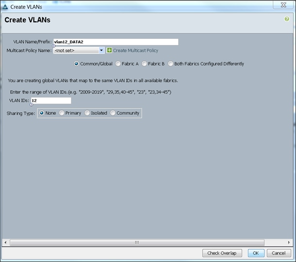
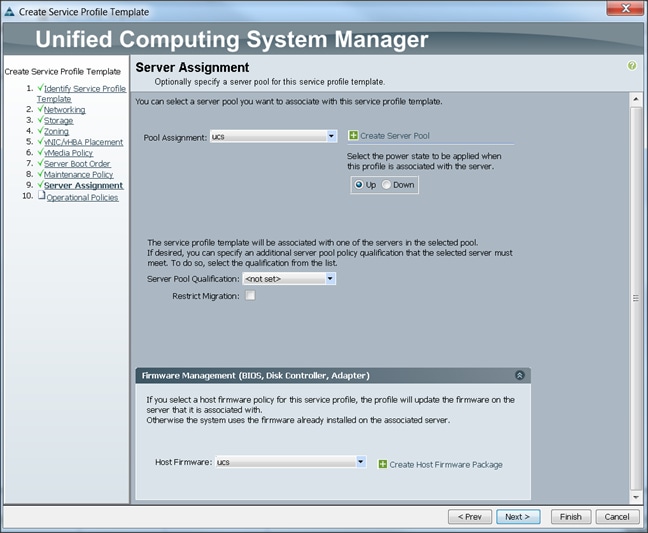
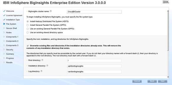
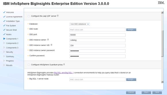
 Feedback