Cisco UCS Integrated Infrastructure for Big Data and Analytics with Hortonworks Data Platform 3.0
Available Languages

Cisco UCS Integrated Infrastructure for Big Data and Analytics with Hortonworks Data Platform 3.0
Design and Deployment Guide of Cisco Integrated Infrastructure for Big Data with Hortonworks Data Platform 3.0 and Cisco UCS C480 M5L Platform
Last Updated: October 21, 2019

About the Cisco Validated Design Program
The Cisco Validated Design (CVD) program consists of systems and solutions designed, tested, and documented to facilitate faster, more reliable, and more predictable customer deployments. For more information, go to:
http://www.cisco.com/go/designzone.
ALL DESIGNS, SPECIFICATIONS, STATEMENTS, INFORMATION, AND RECOMMENDATIONS (COLLECTIVELY, "DESIGNS") IN THIS MANUAL ARE PRESENTED "AS IS," WITH ALL FAULTS. CISCO AND ITS SUPPLIERS DISCLAIM ALL WARRANTIES, INCLUDING, WITHOUT LIMITATION, THE WARRANTY OF MERCHANTABILITY, FITNESS FOR A PARTICULAR PURPOSE AND NONINFRINGEMENT OR ARISING FROM A COURSE OF DEALING, USAGE, OR TRADE PRACTICE. IN NO EVENT SHALL CISCO OR ITS SUPPLIERS BE LIABLE FOR ANY INDIRECT, SPECIAL, CONSEQUENTIAL, OR INCIDENTAL DAMAGES, INCLUDING, WITHOUT LIMITATION, LOST PROFITS OR LOSS OR DAMAGE TO DATA ARISING OUT OF THE USE OR INABILITY TO USE THE DESIGNS, EVEN IF CISCO OR ITS SUPPLIERS HAVE BEEN ADVISED OF THE POSSIBILITY OF SUCH DAMAGES.
THE DESIGNS ARE SUBJECT TO CHANGE WITHOUT NOTICE. USERS ARE SOLELY RESPONSIBLE FOR THEIR APPLICATION OF THE DESIGNS. THE DESIGNS DO NOT CONSTITUTE THE TECHNICAL OR OTHER PROFESSIONAL ADVICE OF CISCO, ITS SUPPLIERS OR PARTNERS. USERS SHOULD CONSULT THEIR OWN TECHNICAL ADVISORS BEFORE IMPLEMENTING THE DESIGNS. RESULTS MAY VARY DEPENDING ON FACTORS NOT TESTED BY CISCO.
CCDE, CCENT, Cisco Eos, Cisco Lumin, Cisco Nexus, Cisco StadiumVision, Cisco TelePresence, Cisco WebEx, the Cisco logo, DCE, and Welcome to the Human Network are trademarks; Changing the Way We Work, Live, Play, and Learn and Cisco Store are service marks; and Access Registrar, Aironet, AsyncOS, Bringing the Meeting To You, Catalyst, CCDA, CCDP, CCIE, CCIP, CCNA, CCNP, CCSP, CCVP, Cisco, the Cisco Certified Internetwork Expert logo, Cisco IOS, Cisco Press, Cisco Systems, Cisco Systems Capital, the Cisco Systems logo, Cisco Unified Computing System (Cisco UCS), Cisco UCS B-Series Blade Servers, Cisco UCS C-Series Rack Servers, Cisco UCS S-Series Storage Servers, Cisco UCS Manager, Cisco UCS Management Software, Cisco Unified Fabric, Cisco Application Centric Infrastructure, Cisco Nexus 9000 Series, Cisco Nexus 7000 Series. Cisco Prime Data Center Network Manager, Cisco NX-OS Software, Cisco MDS Series, Cisco Unity, Collaboration Without Limitation, EtherFast, EtherSwitch, Event Center, Fast Step, Follow Me Browsing, FormShare, GigaDrive, HomeLink, Internet Quotient, IOS, iPhone, iQuick Study, LightStream, Linksys, MediaTone, MeetingPlace, MeetingPlace Chime Sound, MGX, Networkers, Networking Academy, Network Registrar, PCNow, PIX, PowerPanels, ProConnect, ScriptShare, SenderBase, SMARTnet, Spectrum Expert, StackWise, The Fastest Way to Increase Your Internet Quotient, TransPath, WebEx, and the WebEx logo are registered trademarks of Cisco Systems, Inc. and/or its affiliates in the United States and certain other countries.
All other trademarks mentioned in this document or website are the property of their respective owners. The use of the word partner does not imply a partnership relationship between Cisco and any other company. (0809R)
© 2019 Cisco Systems, Inc. All rights reserved.
Table of Contents
Cisco UCS Integrated Infrastructure for Big Data and Analytics
Cisco Unified Computing System
Cisco UCS 6300 Series Fabric Interconnects
Cisco UCS C-Series Rack-Mount Servers
Cisco UCS Virtual Interface Cards
Software Distributions and Versions
Hortonworks Data Platform (HDP 3.0.1)
Red Hat Enterprise Linux (RHEL)
Perform Initial Setup of Cisco UCS 6332 Fabric Interconnects
Configure Fabric Interconnect A
Configure Fabric Interconnect B
Upgrade Cisco UCS Manager Software to Version 4.0(2a)
Add a Block of IP Addresses for KVM Access
Create Pools for Service Profile Templates
Create Policies for Service Profile Templates
Create Host Firmware Package Policy
Create the Local Disk Configuration Policy
Create Service Profile Template
Configure the Storage Provisioning for the Template
Configure Network Settings for the Template
Configure the vMedia Policy for the Template
Configure the Server Boot Order for the Template
Configure the Server Assignment for the Template
Configure the Operational Policies for the Template
Install Red Hat Enterprise Linux 7.5
Create the Red Hat Enterprise Linux (RHEL) 7.5 Local Repository
Create the Red Hat Repository Database
Set Up All Nodes to Use the RHEL Repository
Upgrade the Cisco Network Driver for VIC1387
Disable Transparent Huge Pages
Configure Data Drives on Name Node and Other Management Nodes
Configure Data Drives on Data Nodes
Configure the Filesystem for NameNodes and Datanodes
Prerequisites for HDP Installation
Install and Setup Ambari Server on rhel1
Setup Ambari Server On Admin Node(Rhel1)
Summary of the Installation Process
High Availability for HDFS NameNode and YARN ResourceManager
Configure the HDFS NameNode High Availability
Configure the YARN ResourceManger HA
HDP Post OS Deployment – Enable GPU Isolation and Scheduling
Install the Prerequisites for CUDA
Download and Setup NVIDIA CUDA Deep Neural Network library (cuDNN)
Install nvidia-docker in GPU Nodes
Configure YARN to Running Docker Containers
Run Docker on YARN Using the YARN Service API
Run Docker Container with GPU on YARN
Apache Hadoop YARN Distributed Shell
Run TensorFlow Container Using YARN Distributed Shell
Years ago, most enterprises relied on batch processing to unlock the value of big data and achieved intelligence. As data size and data sources grew, it also drove a demand for real-time analysis which was catered by Spark and Spark streaming for business-critical decisions. In today’s digital world where sensors, Internet of Things (IoT) devices, social media, and online transactions are generating enormous amount of data and companies are struggling to find ways how to better process this data to generate insights and innovation. This drove the next generation of Hadoop which enables Artificial Intelligence and Machine Learning (AI/ML) with deep learning allowing deep learning frameworks and faster compute with CPUs and GPUs to solve problems driving the next generation of platforms.
The emerging trend of Artificial Intelligence requires large amounts of data for its training and Hadoop is a natural fit for storing and retrieving these large amounts of data. Many machine learning tasks especially, deep learning requires the use of GPUs, a specialized, very high-performance processor that is massively parallel in nature. This solution focuses on Hadoop accelerating AI natively where GPUs are part of a Hadoop cluster and are natively scheduled by Hadoop schedulers to process massive amounts of data stored in the same cluster.
Building next-generation big data architecture requires simplified and centralized management, high performance, and a linearly-scaling infrastructure and software platform. Cisco UCS Integrated Infrastructure for Big Data and Analytics with Hortonworks Data Platform (HDP) is an optimal choice where world class performance and reliability are base requirements. It is the strong foundation upon which solutions are built. The Cisco UCS reference architecture has been designed to scale from a small starting solution to thousands of servers and hundreds of petabytes of storage with ease, and all managed from a single pane of glass. Cisco UCS reference architecture also provides the customer with the flexibility an AI workload demands proving choice of server with 2,4,6 or 8 GPUs in a single server catering to different AI compute requirements.
The Hortonworks Data Platform (HDP) is the industry’s enterprise-ready open-source Apache Hadoop framework for distributed storage and processing of large datasets. HDP 3.0 bring the capability of managing and scheduling GPUs, Docker containers into Hadoop enabling AI workloads natively in Hadoop. HDP also enables agile application deployment in a containerized micro-services architecture. Containerization makes it possible to run multiple versions of applications for AI/ML/DL workloads. Furthermore, HDP also supports third-party applications in Docker containers and native YARN containers.
Introduction
Both big data and machine learning technology have progressed to the point where they are being implemented in production systems running 24x7. There exists a very clear need for a proven, dependable, high-performance platform for the ingestion, processing, storage and analysis of the data, as well as the seamless dissemination of the output, results and insights of the analysis.
This solution implements the Cisco UCS Integrated Infrastructure for Big Data and Analytics, a world-class platform specifically designed for demanding workloads that is both easy to scale and easy to manage, even as the requirements grow to thousands of servers and petabytes of storage; and Hortonworks Data Platform, an integrated set of tools designed to enable flexible, fast access to the entire data store, while enabling AI workloads on servers with GPUs.
This CVD implements the following:
· Hortonworks Data Platform 3.0 on Cisco UCS Integrated Infrastructure for Big Data and Analytics
· Install and Enable Docker to be used by YARN 2.0
· Enable CUDA for the GPUs
· Enable GPU as a resource to the Docker Containers through NVIDIA-docker v1
· Enable GPU isolation and scheduling (with Docker Containers) through YARN 2.0
· Downloading a TensorFlow image from NVIDIA Cloud (NGC)
· Adding trusted registries for Docker for YARN 2.0
· Execute a sample TensorFlow job accessing data from Hadoop and running on a Docker container with GPU as a resource scheduled by YARN 2.0
· Installation and setup of the above through Apache Ambari
Caveats and Limitations
The following is beyond the scope of this CVD and therefore is not addressed.
Docker Networking
YARN does not manage Docker networks or Docker multi-host networking. In the implementation of this CVD, container(s) in one host cannot communicate with container(s) in another host.
· Docker Swarm and other docker container orchestration such as Kubernetes are not supported by HDP as they might be competing with YARN
· This document considers TensorFlow or other AI applications in only standalone container spawned and scheduled through YARN 2.0. Distributed TensorFlow and other framework support is expected in later release and will be added as part of addendum
NVIDIA-Docker
· As of this release of Hortonworks and this CVD, only nvidia-docker v1 is supported with HDP 3.0
Many companies recognizing the immense potential of big data and AI/ML technology, are gearing-up to leverage these new capabilities, building-out departments and increasing hiring. However, these efforts face a new set of challenges:
· Making the data available to the diverse set of people who need it
· Enabling access to high-performance computing resources, GPUs, that also scale with data growth
· Allowing people to work with the data using the environments in which they are familiar
· Publishing their results so the organization can make use of it
· Enabling the automated production of those results
· Managing the data for compliance and governance
· Scaling the system as the data grows
· Managing and administering the system in an efficient, cost-effective way
This solution is based on the Cisco UCS Integrated Infrastructure for Big Data and Analytics and includes computing, storage, connectivity, and unified management capabilities to help companies manage the immense amount of data being collected. It is built on the Cisco Unified Computing System (Cisco UCS) infrastructure using Cisco UCS 6332 Series Fabric Interconnects and Cisco UCS C-Series Rack Servers. This architecture is specifically designed for performance and linear scalability for big data and machine learning workloads.
Audience
The intended audience of this document includes, but not limited to, sales engineers, field consultants, professional services, IT managers, partner engineering and customers who want to deploy the Hortonworks Data Platform (HDP 3.0) on Cisco UCS Integrated Infrastructure for Big Data and Analytics. You are assumed to have intermediate level of knowledge for Apache Hadoop and Cisco UCS based scale-out infrastructure.
Purpose of this Document
This document describes the architecture and step by step guidelines of deployment procedures for Hortonworks Data Platform (HDP) 3.0.1 on a 28-node Cisco UCS C240 M5 cluster based on Cisco UCS Integrated Infrastructure for Big Data and Analytics.
Solution Summary
This CVD describes in detail the process for installing Hortonworks 3.0.1 with Apache Spark and Docker containers including the configuration details of the cluster. The current version of Cisco UCS Integrated Infrastructure for Big Data and Analytics offers the following configurations depending on the compute and storage requirements as shown in Table 1.
Table 1 Cisco UCS Integrated Infrastructure for Big Data and Analytics Configuration Options
|
|
Performance (UCS-SP-C240M5-A2) |
Capacity (UCS-SPC240M5L-S1) |
High Capacity (UCS-SP-S3260-BV) |
| Servers |
16 x Cisco UCS C240 M5 Rack Servers with SFF drives |
16 x Cisco UCS C240 M5 Rack Servers with LFF drives |
8 x Cisco UCS S3260 Storage Servers |
| CPU |
2 x Intel Xeon Processor Scalable Family 6132 (2 x 14 cores, 2.6 GHz) |
2 x Intel Xeon Processor Scalable Family 4110 (2 x 8 cores, 2.1 GHz) |
2 x Intel Xeon Processor Scalable Family 6132 (2 x 14 cores, 2.6 GHz) |
| Memory |
6 x 32 GB 2666 MHz (192 GB) |
6 x 32 GB 2666 MHz (192 GB) |
6 x 32 GB 2666 MHz (192 GB) |
| Boot |
M.2 with 2 x 240-GB SSDs |
M.2 with 2 x 240-GB SSDs |
M.2 with 2 x 240-GB SSDs |
| Storage |
24 x 2.4 TB 10K rpm SFF SAS HDDs or 12 x 1.6 TB Enterprise Value SATA SSDs |
12 x 8 TB 7.2K rpm LFF SAS HDDs + 2 SFF rear hot-swappable 1.6 TB Enterprise Value SATA SSDs |
24 x 6 TB 7.2K rpm LFF SAS HDDs |
| VIC |
40 Gigabit Ethernet (Cisco UCS VIC 1387) |
40 Gigabit Ethernet (Cisco UCS VIC 1387) |
40 Gigabit Ethernet (Cisco UCS VIC 1387) |
| Storage Controller |
Cisco 12-Gbps SAS Modular RAID Controller with 4-GB flash-based write cache (FBWC) or Cisco 12-Gbps Modular SAS Host Bus Adapter (HBA) |
Cisco 12-Gbps SAS Modular RAID Controller with 2-GB flash-based write cache (FBWC) or Cisco 12-Gbps Modular SAS Host Bus Adapter (HBA) |
Cisco 12-Gbps SAS Modular RAID Controller with 4-GB flash-based write cache (FBWC) |
| Network Connectivity |
Cisco UCS 6332 Fabric Interconnect |
Cisco UCS 6332 Fabric Interconnect |
Cisco UCS 6332 Fabric Interconnect |
| GPU (Optional) |
2 x NVIDIA TESLA V100 with 32G memory each |
2 x NVIDIA TESLA V100 with 32G memory each |
|
Table 2 High Density GPU Nodes for Data Nodes
|
|
Starter |
High Performance |
| Servers |
4 x Cisco UCS C480 M5 Rack Servers |
4 x Cisco UCS C480 ML M5 Rack Servers |
| CPU |
2 x Intel Xeon Processor Scalable Family 6142 (2 x 16 cores, 2.6 GHz) |
2 x Intel Xeon Processor Scalable Family 6142 (2 x 16 cores, 2.6 GHz) |
| Memory |
12 x 32 GB DDR4 (384 GB) |
12 x 32 GB DDR4 (384 GB) |
| Boot |
M.2 with 2 x 960-GB SSDs |
M.2 with 2 x 960-GB SSDs |
| Storage |
24 x 1.8 TB 10K rpm SFF SAS HDDs or 12 x 1.6 TB Enterprise Value SATA SSDs |
24 x 1.8 TB 10K rpm SFF SAS HDDs or 12 x 1.6 TB Enterprise Value SATA SSDs |
| VIC |
40 Gigabit Ethernet (Cisco UCS VIC 1387) |
40 Gigabit Ethernet (Cisco UCS VIC 1387) |
| Storage Controller |
Cisco 12-Gbps SAS Modular RAID Controller with 4-GB flash-based write cache (FBWC) or Cisco 12-Gbps Modular SAS Host Bus Adapter (HBA) |
Cisco 12-Gbps SAS Modular RAID Controller with 4-GB flash-based write cache (FBWC) or Cisco 12-Gbps Modular SAS Host Bus Adapter (HBA) |
| Network Connectivity |
Cisco UCS 6332 Fabric Interconnect |
Cisco UCS 6332 Fabric Interconnect |
| GPU |
4 x NVIDIA TESLA V100 with 32G memory each |
8 x NVIDIA TESLA V100 with 32G memory each and with NVlink |
Figure 1 illustrates a 16-node starter cluster. The first rack (left) has 16 Cisco UCS C240 M5 servers. Each link in the figure represents a 40 Gigabit Ethernet link from each of the 16 servers directly connected to a Fabric Interconnect. The second rack (right) has 8 x Cisco UCS C240 M5 servers and 4 x Cisco UCS C480 ML M5 Servers. Every server is connected to both Fabric Interconnects.
![]() High density GPU servers have higher storage for OS M.2 drives for docker volumes on the OS drives.
High density GPU servers have higher storage for OS M.2 drives for docker volumes on the OS drives.
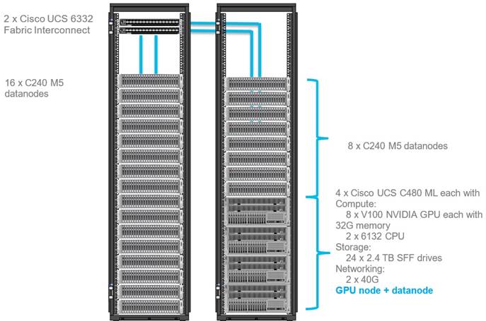
![]() Each Cisco UCS C480 ML M5 has 8 x NVIDIA SXM2 V100 32GB modules with NVLink interconnect. Each Cisco UCS C240 M5 supports up to two PCIe GPU adapters with NVIDIA Tesla V100. For more information about Cisco UCS C240 M5 Sever installation and GPU card configuration rules, go to https://www.cisco.com/c/en/us/td/docs/unified_computing/ucs/c/hw/C240M5/install/C240M5/C240M5_appendix_0101.html
Each Cisco UCS C480 ML M5 has 8 x NVIDIA SXM2 V100 32GB modules with NVLink interconnect. Each Cisco UCS C240 M5 supports up to two PCIe GPU adapters with NVIDIA Tesla V100. For more information about Cisco UCS C240 M5 Sever installation and GPU card configuration rules, go to https://www.cisco.com/c/en/us/td/docs/unified_computing/ucs/c/hw/C240M5/install/C240M5/C240M5_appendix_0101.html
![]() Power requirements per rack must be calculated since the exact values will change based on the power needs of the GPUs.
Power requirements per rack must be calculated since the exact values will change based on the power needs of the GPUs.
![]() 2 x Cisco UCS 6454 Fabric Interconnects can also be used in this reference design. For more information about Cisco UCS 6454 FI, go to https://www.cisco.com/c/en/us/products/collateral/servers-unified-computing/datasheet-c78-741116.html. Cisco UCS 6332 series FI supports 40 Gb end-to-end and is a good choice for higher bandwidth and faster connections. Cisco UCS 6454 can be considered, if you prefer to use 10/25Gb connections and get faster 40/100 Gb uplinks or move to 25Gb in the future.
2 x Cisco UCS 6454 Fabric Interconnects can also be used in this reference design. For more information about Cisco UCS 6454 FI, go to https://www.cisco.com/c/en/us/products/collateral/servers-unified-computing/datasheet-c78-741116.html. Cisco UCS 6332 series FI supports 40 Gb end-to-end and is a good choice for higher bandwidth and faster connections. Cisco UCS 6454 can be considered, if you prefer to use 10/25Gb connections and get faster 40/100 Gb uplinks or move to 25Gb in the future.
Scaling the Solution
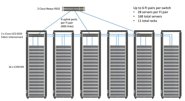
Figure 2 illustrates how to scale the solution. Each pair of Cisco UCS 6332 Fabric Interconnects has 28 Cisco UCS C240 M5 servers connected to it. This allows for four uplinks from each Fabric Interconnect to the Cisco Nexus 9332 switch. Six pairs of 6332 FI’s can connect to a single switch with four uplink ports each. With 28 servers per FI, a total of 168 servers can be supported. Additionally, the can scale to thousands of nodes with the Nexus 9500 series family of switches.
Cisco UCS Integrated Infrastructure for Big Data and Analytics
The Cisco UCS Integrated Infrastructure for Big Data and Analytics solution for Hortonworks Data Platform on Cisco UCS Integrated Infrastructure for Big Data and Analytics, is a highly scalable architecture designed to meet a variety of scale-out application demands with seamless data integration and management integration capabilities built using the components described in this section.
Cisco Unified Computing System
Cisco Unified Computing System is a next-generation solution for blade and rack server computing. Cisco UCS integrates a low-latency; lossless 10 and 40 Gigabit Ethernet unified network fabric with enterprise-class, x86-architecture servers. Cisco UCS is an integrated, scalable, multi-chassis platform in which all resources participate in a unified management domain. Cisco UCS accelerates the delivery of new services simply, reliably, and securely through end-to-end provisioning and migration support for both virtualized and non-virtualized systems. Cisco UCS fuses access layer networking and servers. This high-performance, next-generation server system provides a data center with a high degree of workload agility and scalability.
Cisco UCS 6300 Series Fabric Interconnects
Cisco UCS 6300 Series Fabric Interconnects provide high-bandwidth, low-latency connectivity for servers, with integrated, unified management provided for all connected devices by Cisco UCS Manager (UCSM). Deployed in redundant pairs, Cisco fabric interconnects offer the full active-active redundancy, performance, and exceptional scalability needed to support the large number of nodes that are typical in clusters serving big data applications. Cisco UCS Manager enables rapid and consistent server configuration using service profiles, automating ongoing system maintenance activities such as firmware updates across the entire cluster as a single operation. Cisco UCS Manager also offers advanced monitoring with options to raise alarms and send notifications about the health of the entire cluster.
The Cisco UCS 6300 series Fabric interconnects are a core part of Cisco UCS, providing low-latency, lossless 10 and 40 Gigabit Ethernet, Fiber Channel over Ethernet (FCoE), and Fiber Channel functions with management capabilities for the entire system. All servers attached to Fabric interconnects become part of a single, highly available management domain.
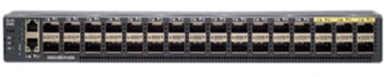
Figure 3 Cisco UCS 6332 UP 32 -Port Fabric Interconnect
Cisco UCS C-Series Rack-Mount Servers
Cisco UCS C-Series Rack-Mount Servers keep pace with Intel Xeon processor innovation by offering the latest processors with increased processor frequency and improved security and availability features. With the increased performance provided by the Intel Xeon Scalable Family Processors, Cisco UCS C-Series servers offer an improved price-to-performance ratio. They also extend Cisco UCS innovations to an industry-standard rack-mount form factor, including a standards-based unified network fabric, Cisco VN-Link virtualization support, and Cisco Extended Memory Technology.
It is designed to operate both in standalone environments and as part of Cisco UCS managed configuration, these servers enable organizations to deploy systems incrementally—using as many or as few servers as needed—on a schedule that best meets the organization’s timing and budget. Cisco UCS C-Series servers offer investment protection through the capability to deploy them either as standalone servers or as part of Cisco UCS. One compelling reason that many organizations prefer rack-mount servers is the wide range of I/O options available in the form of PCIe adapters. C-Series servers support a broad range of I/O options, including interfaces supported by Cisco and adapters from third parties.
Cisco UCS C240 M5 Rack-Mount Server
The Cisco UCS C240 M5 Rack-Mount Server (Figure 4) is a 2-socket, 2-Rack-Unit (2RU) rack server offering industry-leading performance and expandability. It supports a wide range of storage and I/O-intensive infrastructure workloads, from big data and analytics to collaboration. Cisco UCS C-Series Rack Servers can be deployed as standalone servers or as part of a Cisco Unified Computing System managed environment to take advantage of Cisco’s standards-based unified computing innovations that help reduce customers’ Total Cost of Ownership (TCO) and increase their business agility.
In response to ever-increasing computing and data-intensive real-time workloads, the enterprise-class Cisco UCS C240 M5 server extends the capabilities of the Cisco UCS portfolio in a 2RU form factor. It incorporates the Intel Xeon Scalable processors, supporting up to 20 percent more cores per socket, twice the memory capacity, and five times more
Non-Volatile Memory Express (NVMe) PCI Express (PCIe) Solid-State Disks (SSDs) compared to the previous generation of servers. These improvements deliver significant performance and efficiency gains that will improve your application performance. The Cisco UCS C240 M5 delivers outstanding levels of storage expandability with exceptional performance, along with the following:
· Latest Intel Xeon Scalable CPUs with up to 28 cores per socket
· Up to 24 DDR4 DIMMs for improved performance
· Up to 26 hot-swappable Small-Form-Factor (SFF) 2.5-inch drives, including 2 rear hot-swappable SFF drives (up to 10 support NVMe PCIe SSDs on the NVMe-optimized chassis version), or 12 Large-Form- Factor (LFF) 3.5-inch drives plus 2 rear hot-swappable SFF drives
· Support for 12-Gbps SAS modular RAID controller in a dedicated slot, leaving the remaining PCIe Generation 3.0 slots available for other expansion cards
· Modular LAN-On-Motherboard (mLOM) slot that can be used to install a Cisco UCS Virtual Interface Card (VIC) without consuming a PCIe slot, supporting dual 10- or 40-Gbps network connectivity
· Dual embedded Intel x550 10GBASE-T LAN-On-Motherboard (LOM) ports
· Modular M.2 or Secure Digital (SD) cards that can be used for boot
Figure 4 Cisco UCS C240 M5 Rack-Mount Server – Front View
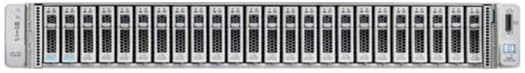

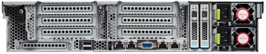
Figure 5 Cisco UCS C240 M5 Rack-Mount Server – Rear View
Cisco UCS C480 M5 Rack-Mount Server
The Cisco UCS C480 M5 Rack-Mount Server is a storage and I/O-optimized enterprise-class rack-mount server that delivers industry-leading performance for in-memory databases, big data analytics, virtualization, Virtual Desktop Infrastructure (VDI), and bare-metal applications. The Cisco UCS C480 M5 (Figure 6) delivers outstanding levels of expandability and performance for standalone or Cisco Unified Computing System managed environments in a 4RU form-factor. Because of its modular design, you pay for only what you need. It offers these capabilities:
· Latest Intel Xeon Scalable processors with up to 28 cores per socket and support for two-or four-processor configurations
· 2666-MHz DDR4 memory and 48 DIMM slots for up to 6 Terabytes (TB) of total memory
· 12 PCI Express (PCIe) 3.0 slots
- Six x 8 full-height, full length slots
- Six x16 full-height, full length slots
· Flexible storage options with support up to 32 Small-Form-Factor (SFF) 2.5-inch, SAS, SATA, and PCIe NVMe disk drives
· Cisco 12-Gbps SAS Modular RAID Controller in a dedicated slot
· Internal Secure Digital (SD) and M.2 boot options
· Dual embedded 10 Gigabit Ethernet LAN-On-Motherboard (LOM) ports
Figure 6 Cisco UCS C480 M5 Rack-Mount Server – Front View

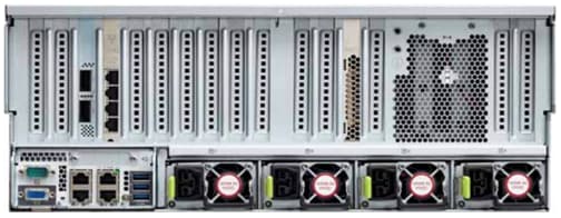
Figure 7 Cisco UCS C480 M5 Rack-Mount Server – Rear View
For more information about Cisco UCS C480 M5 Rack Server, go to: https://www.cisco.com/c/en/us/products/collateral/servers-unified-computing/ucs-c-series-rack-servers/datasheet-c78-739291.html
Cisco UCS C480 ML M5 Rack Server
The Cisco UCS C480 ML M5 Rack Server is a purpose-built server for Deep Learning. It is storage and I/O optimized to deliver an industry-leading performance for training Models. The Cisco UCS C480 ML M5 delivers outstanding levels of storage expandability and performance options for standalone or Cisco Unified Computing System managed environments in a 4RU form factor. Because of its modular design, you pay for only what you need. It offers these capabilities:
· 8 NVIDIA SXM2 V100 32G modules with NVLink interconnect
· Latest Intel Xeon Scalable processors with up to 28 cores per socket and support for two processor configurations
· 2666-MHz DDR4 memory and 24 DIMM slots for up to 3 terabytes (TB) of total memory
· 4 PCI Express (PCIe) 3.0 slots for 100G UCS VIC 1495
· Flexible storage options with support for up to 24 Small-Form-Factor (SFF) 2.5-inch, SAS/SATA Solid-State Disks (SSDs) and Hard-Disk Drives (HDDs)
· Up to 6 PCIe NVMe disk drives
· Cisco 12-Gbps SAS Modular RAID Controller in a dedicated slot
· M.2 boot options
· Dual embedded 10 Gigabit Ethernet LAN-On-Motherboard (LOM) ports
Figure 8 Cisco UCS C480 ML M5 Purpose Built Deep Learning Server – Front View

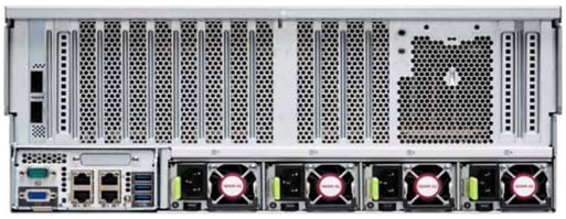
Figure 9 Cisco UCS C480 ML M5 Purpose Built Deep Learning Server – Rear View
For more information about Cisco UCS C480 ML M5 Server, go to: https://www.cisco.com/c/dam/en/us/products/collateral/servers-unified-computing/ucs-c-series-rack-servers/c480m5-specsheet-ml-m5-server.pdf
Table 3 lists the features and benefits of Cisco UCS C480 ML M5 Server.
Table 3 Feature and Benefits for Cisco UCS C480 ML M5 Server
| Feature |
Benefits |
| 8 x NVIDIA SXM2 V100 32GB modules with NVLink interconnect |
Fast Deep Learning model training
|
| Modular storage support with up to 24 front accessible hot-swappable Hard Disk Drives (HDDs) and Solid-State Disks (SSDs) |
Modularity to right-size storage options to match training requirements Flexibility to expand as storage needs increase |
| High-capacity memory support of up to 3 TB using 128-GB DIMMs |
Large memory footprint to deliver performance and capacity for large model training |
| Up to 6 PCIe NVMe drives |
Up to 6 Gen3 x4 lanes NVMe drives for extreme I/O performance for faster model training |
| Support for up to 4 PCIe Generation 3.0 slots
|
Support for up to four 10/25 or 40/100G Cisco VICs |
| Hot-swappable, redundant power supplies |
Increased high availability |
| Integrated dual 10-Gbps Ethernet |
Increased network I/O performance and additional network options |
Cisco UCS Virtual Interface Cards
Cisco UCS Virtual Interface Cards (VICs) are unique to Cisco. Cisco UCS Virtual Interface Cards incorporate next-generation converged network adapter (CNA) technology from Cisco and offer dual 10- and 40-Gbps ports designed for use with Cisco UCS servers. Optimized for virtualized networking, these cards deliver high performance and bandwidth utilization, and support up to 256 virtual devices.
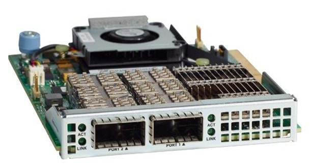
The Cisco UCS Virtual Interface Card 1387 offers dual-port Enhanced Quad Small Form-Factor Pluggable (QSFP+) 40 Gigabit Ethernet and Fiber Channel over Ethernet (FCoE) in a modular-LAN-on-motherboard (mLOM) form factor. The mLOM slot can be used to install a Cisco VIC without consuming a PCIe slot providing greater I/O expandability.
Figure 10 Cisco UCS VIC 1387
For more information about Cisco UCS Adapters, go to: https://www.cisco.com/c/en/us/products/interfaces-modules/unified-computing-system-adapters/index.html
Cisco UCS Manager
Cisco UCS Manager (UCSM) resides within the Cisco UCS 6300 Series Fabric Interconnect. It makes the system self-aware and self-integrating, managing all of the system components as a single logical entity. Cisco UCS Manager can be accessed through an intuitive GUI, a CLI, or an XML API. Cisco UCS Manager uses service profiles to define the personality, configuration, and connectivity of all resources within Cisco UCS, radically simplifying provisioning of resources so that the process takes minutes instead of days. This simplification allows IT departments to shift their focus from constant maintenance to strategic business initiatives.
For more information about Cisco UCS Manger, go to: https://www.cisco.com/c/en/us/products/servers-unified-computing/ucs-manager/index.html
NVIDIA GPU
Graphics Processing Units or GPUs are specialized processors designed to render images, animation and video for computer displays. They perform this task by running many operations simultaneously. While the number and kinds of operations they can do are limited, they make up for it by being able run many thousands in parallel. As the graphics capabilities of GPUs increased, it soon became apparent that the massive parallelism of GPUs could be put to other uses beside rendering graphics.
NVIDIA GPU used in this document, NVIDIA Tesla V100, is advanced data center GPU built to accelerate AI, HPC, and graphics. It is powered by NVIDIA Volta architecture, comes in 16 and 32 GB configurations.
NVIDIA GPUs bring two key advantages to the table. First, they make possible solutions that were simply not computationally possible before. Second, by providing the same processing power as scores of traditional CPUs they reduce the requirements for rack space, power, networking and cooling in the data center.
NVIDIA CUDA
GPUs are very good at running the same operation on different data simultaneously. This is often referred to as single instruction, multiple data, or SIMD. This is exactly what’s needed to render graphics but many other computing problems can benefit from this approach. As a result, NVIDIA created CUDA. CUDA is a parallel computing platform and programming model that makes it possible to use a GPU for many general-purpose computing tasks via commonly used programming languages like C and C++.
In addition to the general-purpose computing capabilities that CUDA enables there is also a special CUDA library for deep learning called the CUDA Deep Neural Network library, or cuDNN. cuDNN makes it easier to implement deep machine learning architectures that take full advantage of the GPU’s capabilities.
Hortonworks Data Platform
The Hortonworks Data Platform (HDP 3.0.1) delivers essential capabilities in a completely open, integrated and tested platform that is ready for enterprise usage. With Hadoop YARN at its core, HDP provides flexible enterprise data processing across a range of data processing engines, paired with comprehensive enterprise capabilities for governance, security and operations.
All the integration of the entire solution is thoroughly tested and fully documented. By taking the guesswork out of building out a Hadoop deployment, HDP gives a streamlined path to success in solving real business problems.
Hortonworks Data Platform (HDP) 3.0 delivers significant new features, including the ability to launch apps in a matter of minutes and address new use cases for high-performance deep learning and machine learning apps. In addition, this new version of HDP enables enterprises to gain value from their data faster, smarter, in a hybrid environment.
Apache Ambari
Apache Ambari is a completely open source management platform. It performs provisioning, managing, securing, and monitoring Apache Hadoop clusters. Apache Ambari is a part of Hortonworks Data Platform and it allows enterprises to plan and deploy HDP cluster. It also provides ongoing cluster maintenance and management.
Ambari provides an intuitive Web UI as well as an extensive REST API framework which is very useful for automating cluster operations.
Below are the core benefits that Hadoop operators get with Ambari:
· Simplified Installation, Configuration and Management. Easily and efficiently create, manage and monitor clusters at scale. Takes the guesswork out of configuration with Smart Configs and Cluster Recommendations. Enables repeatable, automated cluster creation with Ambari Blueprints.
· Centralized Security Setup. Reduce the complexity to administer and configure cluster security across the entire platform. Helps automate the setup and configuration of advanced cluster security capabilities such as Kerberos and Apache Ranger.
· Full Visibility into Cluster Health. Ensure your cluster is healthy and available with a holistic approach to monitoring. Configures predefined alerts — based on operational best practices — for cluster monitoring. Captures and visualizes critical operational metrics — using Grafana — for analysis and troubleshooting. Integrated with Hortonworks SmartSense for proactive issue prevention and resolution.
· Highly Extensible and Customizable. Fit Hadoop seamlessly into your enterprise environment. Highly extensible with Ambari Stacks for bringing custom services under management, and with Ambari Views for customizing the Ambari Web UI.
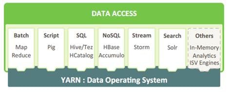
HDP for Data Access
With YARN at its foundation, HDP provides a range of processing engines that allow users to interact with data in multiple and parallel ways, without the need to stand up individual clusters for each data set/application. Some applications require batch while others require interactive SQL or low-latency access with NoSQL. Other applications require search, streaming or in-memory analytics. Apache Solr, Storm and Spark fulfill those needs respectively.
To function as a true data platform, the YARN-based architecture of HDP enables the widest possible range of access methods to coexist within the same cluster avoiding unnecessary and costly data silos.
As shown in Figure 11, HDP Enterprise natively provides for the following data access types:
· Batch – Apache MapReduce has served as the default Hadoop processing engine for years. It is tested and relied upon by many existing applications.
· Interactive SQL Query - Apache Hive is the de facto standard for SQL interactions at petabyte scale within Hadoop. Hive delivers interactive and batch SQL querying across the broadest set of SQL semantics.
· Search - HDP integrates Apache Solr to provide high-speed indexing and sub-second search times across all your HDFS data.
· Scripting - Apache Pig is a scripting language for Hadoop that can run on MapReduce or Apache Tez, allowing you to aggregate, join and sort data.
· Low-latency access via NoSQL - Apache HBase provides extremely fast access to data as a columnar format, NoSQL database. Apache Accumulo also provides high-performance storage and retrieval, but with fine-grained access control to the data.
· Streaming - Apache Storm processes streams of data in real time and can analyze and take action on data as it flows into HDFS.
Docker Containerization
Hortonworks Data Platform (HDP 3.0) makes use of container technology. Containers are conceptually similar to virtual machines, but instead of virtualizing the hardware, a container virtualizes the operating system. With a VM there is an entire operating system sitting on top of the hypervisor. Containers dispense with this time-consuming and resource hungry requirement by sharing the host system’s kernel. As a result, a container is far smaller, and its lightweight nature means they can be instantiated quickly. In fact, they can be instantiated so quickly that new application architectures are possible.
Docker is an open-source project that performs operating-system-level virtualization, also known as "containerization." It uses Linux kernel features like namespaces and control groups to create containers. These features are not new, but Docker has taken these concepts and improved them in the following ways:
· Ease of use: Docker makes easier for anyone — developers, systems admins, architects and others — to take advantage of containers in order to quickly build and test portable applications. It allows anyone to package an application on their development system, which can then run unmodified on any cloud or bare metal server. The basic idea is to create a “build once, run anywhere” system.
· Speed: Docker containers are very fast with a small footprint. Ultimately, containers are just sandboxed environments running on the kernel, so they take up few resources. You can create and run a Docker container in seconds. Compare this to a VM which takes much longer because it has to boot up a full virtual operating system every time.
· Modularity: Docker makes it easy to take an application and breaks its functionality into separate individual containers. These containers can then be spun up and run as needed. This is particularly useful for cases where an application needs to hold and lock a particular resource, like a GPU, and then release it once it’s done using it. Modularity also enables each component, i.e., container to be updated independently.
· Scalability: modularity enables scalability. With different parts of the system running in different containers it becomes possible, and with Docker, it becomes easy to connect these containers together to create an application, which can then be scaled out as needed.
YARN Support For Docker
Containerization provides YARN support for Docker containers, which makes it easier to bundle libraries and dependencies along with their application, allowing third-party applications to run on Apache Hadoop (for example, containerized applications), enabling:
· Faster time to deployment by enabling third-party apps.
· The ability to run multiple versions of an application, enabling users to rapidly create features by developing and testing new versions of services without disrupting old ones.
· Improved resource utilization and increased task throughput for containers, yielding faster time to market for services.
· Orchestration of stateless distributed applications.
· Packaging libraries for Spark application, eliminating the need for operations to deploy those libraries cluster wide.
Figure 12 Containerized Application on Apache Hadoop YARN 3.1
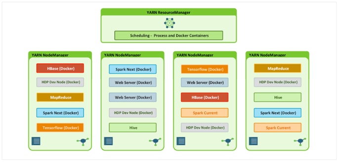
As shown in Figure 12, YARN Services Framework in addition with Docker containerization, it is now possible to run both existing Hadoop frameworks, such as Hive, Spark, etc., and new containerized workloads on the same underlying infrastructure. Apache Hadoop 3.1 further improved these capabilities to enable advanced use cases such as TensorFlow and HBase.
NVIDIA Docker
Docker containers are platform-agnostic, but also hardware-agnostic. This presents a problem when using specialized hardware such as NVIDIA GPUs which require kernel modules and user-level libraries to operate. As a result, Docker does not natively support NVIDIA GPUs within containers.
One of the early workarounds to this problem was to fully install the NVIDIA drivers inside the container and map in the character devices corresponding to the NVIDIA GPUs (for example, /dev/nvidia0) on launch. This solution is brittle because the version of the host driver must exactly match the version of the driver installed in the container. This requirement drastically reduced the portability of these early containers, undermining one of Docker’s more important features.
To enable portability in Docker images that leverage NVIDIA GPUs, NVIDIA developed nvidia-docker, an open-source project hosted on GitHub that provides the two critical components needed for portable GPU-based containers:
driver-agnostic CUDA images; and a Docker command line wrapper that mounts the user mode components of the driver and the GPUs (character devices) into the container at launch.
nvidia-docker is essentially a wrapper around the docker command that transparently provisions a container with the necessary components to execute code on the GPU.
![]() As of the publishing of this CVD, Hortonworks only supports nvidia-docker version 1.
As of the publishing of this CVD, Hortonworks only supports nvidia-docker version 1.
GPU Pooling and Isolation
GPU pooling and isolation allows GPU to be a first-class resource type in Hadoop, making it easier for customers to run machine learning and deep learning workloads.
· Compute-intensive analytics require not only a large compute pool, but also a fast and expensive processing pool with GPUs in tandem
· Customers can share cluster-wide GPU resources without having to dedicate a GPU node to a single tenant or workload
· GPU isolation dedicates a GPU to an application so that no other application has access to that GPU
When it comes to resource scheduling, it is important to recognize GPU as a resource. YARN extends the resource model to more flexible mode which makes it easier to add new countable resource-types. When GPU is added as resource type, YARN can schedule applications on GPU machines. Furthermore, by specifying the number of requested GPU to containers, YARN can find machines with available GPUs to satisfy container requests.
Figure 13 YARN Scheduling for GPU/Non-GPU Applications
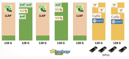
![]() When GPU scheduling is enabled, YARN can schedule non-GPU applications such as LLAP, Tez, and etc. to servers without GPU. Moreover, YARN can allocate GPU applications such as TensorFlow, Caffe, MXNet, and so on, to servers with GPU.
When GPU scheduling is enabled, YARN can schedule non-GPU applications such as LLAP, Tez, and etc. to servers without GPU. Moreover, YARN can allocate GPU applications such as TensorFlow, Caffe, MXNet, and so on, to servers with GPU.
Red Hat Ansible Automation
Red Hat Ansible Automation is a powerful IT automation tool. It is capable of provisioning numerous types of resources and deploying applications. It can configure and manage devices and operating system components. Due to its simplicity, extensibility, and portability, this solution extensively utilizes Ansible for performing repetitive deployment steps across the nodes.
![]() For more information about Ansible, go to: https://www.redhat.com/en/technologies/management/ansible
For more information about Ansible, go to: https://www.redhat.com/en/technologies/management/ansible
Requirements
This CVD describes the architecture and deployment procedures for Hortonworks Data Platform (HDP) 3.0.1 on a 28 Cisco UCS C240 M5 node cluster based on Cisco UCS Integrated Infrastructure for Big Data and Analytics. The solution goes into detail configuring HDP 3.0.1 on the Cisco UCS Integrated infrastructure for Big Data. In addition, it also details the configuration for Hortonworks Dataflow for various use cases.
The cluster configuration consists of the following:
· 2 Cisco UCS 6332UP Fabric Interconnects
· 24 Cisco UCS C240 M5 Rack-Mount servers
· 4 Cisco UCS C480 ML M5 Rack-Mount server
· 8 NVIDIA GPU in each Cisco UCS C480 ML M5
· 2 Cisco R42610 standard racks
· 4 Vertical Power distribution units (PDUs) (Country Specific) per rack
Rack and PDU Configuration
Each rack consists of two vertical PDUs. The first rack consists of two Cisco UCS 6332UP Fabric Interconnects, 16 Cisco UCS C240 M5 Rack Servers connected to each of the vertical PDUs for redundancy; thereby ensuring availability during power source failure. The second rack consists of 8 Cisco UCS C240 M5 Servers and 4 Cisco UCS C480 ML M5 connected to each of the vertical PDUs for redundancy; thereby ensuring availability during power source failure, similar to the first rack.
![]() Please contact your Cisco representative for country specific information.
Please contact your Cisco representative for country specific information.
Table 4 Port Configuration on Fabric Interconnects
| Port Type |
Port Number |
| Network |
29-32 |
| Server |
1-28 |
Cabling for Cisco UCS C240 M5
The Cisco UCS C240 M5 rack server is equipped with 2 x Intel Xeon Processor Scalable Family 6132 (2 x 14 cores, 2.6 GHz), 192 GB of memory, Cisco UCS Virtual Interface Card 1387 Cisco 12-Gbps SAS Modular Raid Controller with 4-GB FBWC, 26 x 1.8 TB 10K rpm SFF SAS HDDs or 12 x 1.6 TB Enterprise Value SATA SSDs, M.2 with 2 x 240-GB SSDs for Boot.
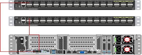
Figure 14 illustrates the port connectivity between the Fabric Interconnect, and Cisco UCS C240 M5 server. Sixteen Cisco UCS C240 M5 servers are used in Master rack configurations.
Figure 14 Cisco UCS C240 M5 and 6300 Series Fabric Interconnect Port Connectivity
For information about physical connectivity and single-wire management go to:
For more information about physical connectivity illustrations and cluster setup, go to:
Software Distributions and Versions
The software distributions required versions are listed below.
Hortonworks Data Platform (HDP 3.0.1)
The Hortonworks Data Platform supported is HDP 3.0.1. For more information, go to: http://www.hortonworks.com.
Red Hat Enterprise Linux (RHEL)
The operating system supported is Red Hat Enterprise Linux 7.5. For more information, go to: http://www.redhat.com.
Software Versions
The software versions tested and validated in this document are shown in Table 5.
| Layer |
Component |
Version or Release |
| Compute |
Cisco UCS C240 M5 |
C240M5.4.0.2a |
| Cisco UCS C480 ML M5 |
|
|
| Network |
Cisco UCS 6332 |
UCS 4.0(2a) |
| Cisco UCS VIC1387 Firmware |
4.3(2a) |
|
| Cisco UCS VIC1387 Driver |
3.1.137.5 |
|
| Storage |
SAS Expander |
65.02.15.00 |
| Cisco 12G Modular Raid controller |
50.6.0-1952 |
|
| Software |
Red Hat Enterprise Linux Server |
7.5 |
| Cisco UCS Manager |
4.0(2a) |
|
| HDP |
3.0.1 |
|
| Docker |
1.13.1 |
|
| Ansible |
2.4.6.0 |
|
| Nvidia-docker |
1.0.1 |
|
| GPU |
CUDA |
9.2 |
| NVIDIA GPU Driver |
396.44 |
![]() The latest drivers can be downloaded from this link:
The latest drivers can be downloaded from this link:
https://software.cisco.com/download/home/283862063/type/283853158/release/3.1%25283%2529.
![]() The latest supported RAID controller driver is already included with the RHEL 7.5 operating system.
The latest supported RAID controller driver is already included with the RHEL 7.5 operating system.
![]() Cisco UCS C240 M5 Rack Servers with Intel Scalable Processor Family CPUs are supported from Cisco UCS firmware 3.2 onwards.
Cisco UCS C240 M5 Rack Servers with Intel Scalable Processor Family CPUs are supported from Cisco UCS firmware 3.2 onwards.
Fabric Configuration
This section provides the details to configure a fully redundant, highly available Cisco UCS 6332 fabric configuration. The following is the high-level workflow to setup Cisco UCS:
· Initial setup of the Fabric Interconnect A and B
· Connect to Cisco UCS Manager using virtual IP address of using the web browser
· Launch Cisco UCS Manager
· Enable server and uplink ports
· Start discovery process
· Create pools and polices for service profile template
· Create Service Profile template
· Create service profile for each server from service profile template
· Associate Service Profiles to servers5
Perform Initial Setup of Cisco UCS 6332 Fabric Interconnects
This section describes the initial setup of the Cisco UCS 6332 Fabric Interconnects A and B.
Configure Fabric Interconnect A
To configure Fabric Interconnect A, follow these steps:
1. Connect to the console port on the first Cisco UCS 6332 Fabric Interconnect.
2. At the prompt to enter the configuration method, enter console to continue.
3. If asked to either perform a new setup or restore from backup, enter setup to continue.
4. Enter y to continue to set up a new Fabric Interconnect.
5. Enter y to enforce strong passwords.
6. Enter the password for the admin user.
7. Enter the same password again to confirm the password for the admin user.
8. When asked if this fabric interconnect is part of a cluster, answer y to continue.
9. Enter A for the switch fabric.
10. Enter the cluster name for the system name.
11. Enter the Mgmt0 IPv4 address.
12. Enter the Mgmt0 IPv4 netmask.
13. Enter the IPv4 address of the default gateway.
14. Enter the cluster IPv4 address.
15. To configure DNS, answer y.
16. Enter the DNS IPv4 address.
17. Answer y to set up the default domain name.
18. Enter the default domain name.
19. Review the settings that were printed to the console, and if they are correct, answer yes to save the configuration.
20. Wait for the login prompt to make sure the configuration has been saved.
Configure Fabric Interconnect B
To configure Fabric Interconnect B, follow these steps:
1. Connect to the console port on the second Cisco UCS 6332 Fabric Interconnect.
2. When prompted to enter the configuration method, enter console to continue.
3. The installer detects the presence of the partner Fabric Interconnect and adds this fabric interconnect to the cluster. Enter y to continue the installation.
4. Enter the admin password that was configured for the first Fabric Interconnect.
5. Enter the Mgmt0 IPv4 address.
6. Answer yes to save the configuration.
7. Wait for the login prompt to confirm that the configuration has been saved.
For more information about configuring Cisco UCS 6332 Series Fabric Interconnect, go to:
Log Into Cisco UCS Manager
To log into Cisco UCS Manager, follow these steps:
1. Open a Web browser and navigate to the Cisco UCS 6332 Fabric Interconnect cluster address.
2. Click the Launch link to download the Cisco UCS Manager software.
3. If prompted to accept security certificates, accept as necessary.
4. When prompted, enter admin for the username and enter the administrative password.
5. Click Login to log in to the Cisco UCS Manager.
Upgrade Cisco UCS Manager Software to Version 4.0(2a)
This document assumes the use of UCS 4.0(2a). Refer to the Cisco UCS 4.0 Release (upgrade Cisco UCS Manager software and UCS 6332 Fabric Interconnect software to version 4.0(2a). Also, make sure the Cisco UCS C-Series version 4.0(2a) software bundles are installed on the Fabric Interconnects.
![]() Upgrading Cisco UCS firmware is beyond the scope of this document. However for complete Cisco UCS Install and Upgrade Guides, go to: https://www.cisco.com/c/en/us/support/servers-unified-computing/ucs-manager/products-installation-guides-list.html
Upgrading Cisco UCS firmware is beyond the scope of this document. However for complete Cisco UCS Install and Upgrade Guides, go to: https://www.cisco.com/c/en/us/support/servers-unified-computing/ucs-manager/products-installation-guides-list.html
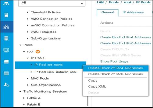
Add a Block of IP Addresses for KVM Access
To create a block of KVM IP addresses for server access in the Cisco UCS environment, follow these steps:
1. Select the LAN tab at the top of the left window.
2. Select Pools > root > IpPools > Ip Pool ext-mgmt.
3. Right-click IP Pool ext-mgmt.
4. Select Create Block of IPv4 Addresses.
Figure 15 Adding a Block of IPv4 Addresses for KVM Access Part 1
5. Enter the starting IP address of the block and number of IPs needed, as well as the subnet and gateway information.
Figure 16 Adding Block of IPv4 Addresses for KVM Access Part 2
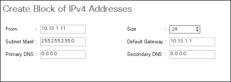
6. Click OK to create the IP block.
7. Click OK in the message box.
Enable Uplink Ports
To enable uplinks ports, follow these steps:
1. Select the Equipment tab on the top left of the window.
2. Select Equipment > Fabric Interconnects > Fabric Interconnect A (primary) > Fixed Module.
3. Expand the Unconfigured Ethernet Ports section.
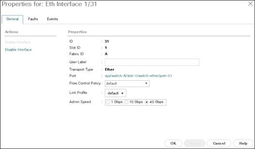
4. Select port 29-32 that is connected to the uplink switch, right-click, then select Reconfigure > Configure as Uplink Port.
5. Select Show Interface and select 40GB for Uplink Connection.
6. A pop-up window appears to confirm your selection. Click Yes then OK to continue.
7. Select Equipment > Fabric Interconnects > Fabric Interconnect B (subordinate) > Fixed Module.
8. Expand the Unconfigured Ethernet Ports section.
9. Select port number 29-32, which is connected to the uplink switch, right-click, then select Reconfigure > Configure as Uplink Port.
10. Select Show Interface and select 40GB for Uplink Connection.
11. A pop-up window appears to confirm your selection. Click Yes then OK to continue.
Figure 17 Enabling Uplink Ports Part1
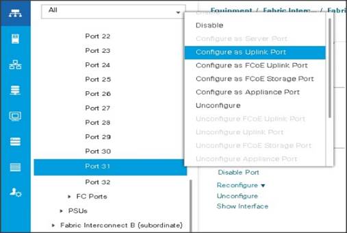
Figure 17 Enabling Uplink Ports Part2
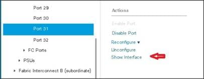
Figure 18 Enabling Uplink Ports Part 3
Configure VLANs
VLANs are configured as in shown in Table 6.
| VLAN |
NIC Port |
Function |
| VLAN13 |
eth0 |
Data |
The NIC will carry the data traffic from VLAN13. A single vNIC is used in this configuration and the Fabric Failover feature in Fabric Interconnects will take care of any physical port down issues. It will be a seamless transition from an application perspective.
To configure VLANs in the Cisco UCS Manager GUI, follow these steps:
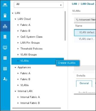
1. Select the LAN tab in the left pane in the UCSM GUI.
2. Select LAN > LAN Cloud > VLANs.
3. Right-click the VLANs under the root organization.
4. Select Create VLANs to create the VLAN.
Figure 19 Creating a VLAN
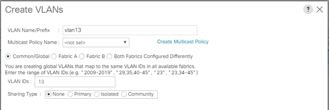
5. Enter vlan13 for the VLAN Name.
6. Keep multicast policy as <not set>.
7. Select Common/Global for vlan16.
8. Enter 13 in the VLAN IDs field for the Create VLAN IDs.
9. Click OK and then, click Finish.
10. Click OK in the success message box.
Figure 20 Creating VLAN for Data
11. Click OK and then click Finish.
Enable Server Ports
To enable server ports, follow these steps:
1. Select the Equipment tab on the top left of the window.
2. Select Equipment > Fabric Interconnects > Fabric Interconnect A (primary) > Fixed Module.
3. Expand the Unconfigured Ethernet Ports section.
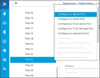
4. Select all the ports that are connected to the Servers right-click them and select Reconfigure > Configure as a Server Port.
5. A pop-up window appears to confirm your selection. Click Yes then OK to continue.
6. Select Equipment > Fabric Interconnects > Fabric Interconnect B (subordinate) > Fixed Module.
7. Expand the Unconfigured Ethernet Ports section.
8. Select all the ports that are connected to the Servers right-click them, and select Reconfigure > Configure as a Server Port.
9. A pop-up window appears to confirm your selection. Click Yes, then OK to continue.
Figure 21 Enabling Server Ports
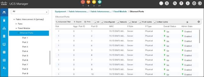
After the Server Discovery, Port 29-32 will be a Network Port and 1-28 will be Server Ports.
Figure 22 Ports Status after the Server Discover
Create Pools for Service Profile Templates
Create an Organization
Organizations are used as a means to arrange and restrict access to various groups within the IT organization, thereby enabling multi-tenancy of the compute resources. This document does not assume the use of Organizations; however, the necessary steps are provided for future reference.
To configure an organization within the Cisco UCS Manager GUI, follow these steps:
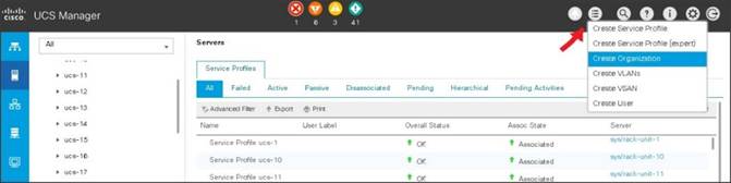
1. Click Quick Action icon on the top right corner in the right pane in the Cisco UCS Manager GUI.
2. Select Create Organization from the options
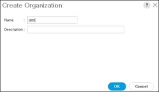
3. Enter a name for the organization.
4. (Optional) Enter a description for the organization.
5. Click OK.
6. Click OK in the success message box.
Create MAC Address Pools
To create MAC address pools, follow these steps:
1. Select the LAN tab on the left of the window.
2. Select Pools > root > MAC Pools
3. Right-click MAC Pools under the root organization.
4. Select Create MAC Pool to create the MAC address pool. Enter ucs for the name of the MAC pool.
5. (Optional) Enter a description of the MAC pool.
6. Select Assignment Order Sequential.
7. Click Next.
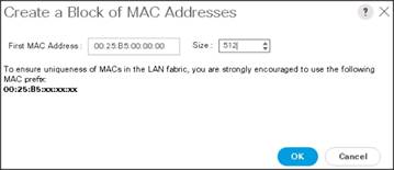
8. Click Add.
9. Specify a starting MAC address.
10. Specify a size of the MAC address pool, which is sufficient to support the available server resources.
11. Click OK.
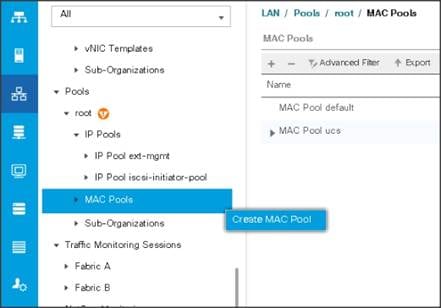
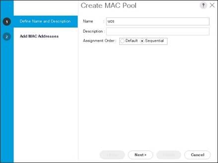
Figure 23 Specifying first MAC Address and Size
12. Click Finish.
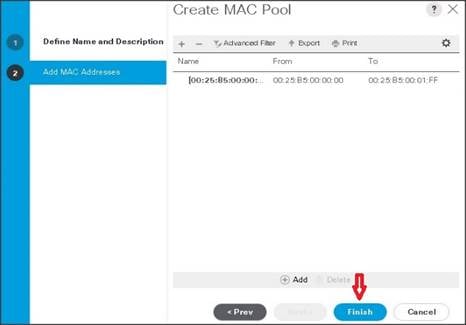
13. When the message box displays, click OK.

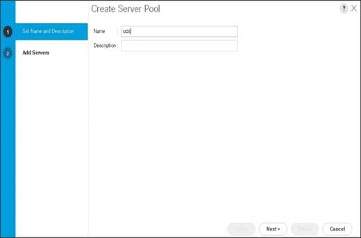
Create a Server Pool
A server pool contains a set of servers. These servers typically share the same characteristics. Those characteristics can be their location in the chassis, or an attribute such as server type, amount of memory, local storage, type of CPU, or local drive configuration. You can manually assign a server to a server pool or use server pool policies and server pool policy qualifications to automate the assignment.
To configure the server pool within the Cisco UCS Manager GUI, follow these steps:
1. Select the Servers tab in the left pane in the Cisco UCS Manager GUI.
2. Select Pools > root.
3. Right-click the Server Pools.
4. Select Create Server Pool.
5. Enter your required name (ucs) for the Server Pool in the name text box.
6. (Optional) enter a description for the organization.
7. Click Next > to add the servers.
8. Select all the Cisco UCS C240M5 servers to be added to the server pool that was previously created (ucs), then Click >> to add them to the pool.
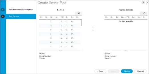
9. Click Finish.
10. Click OK and then click Finish.
Create Policies for Service Profile Templates
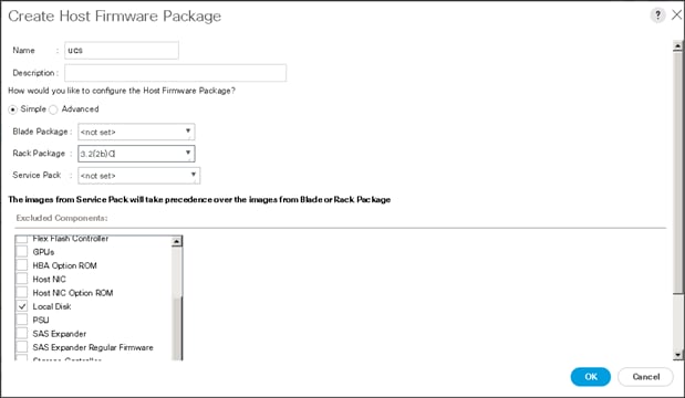
Create Host Firmware Package Policy
Firmware management policies allow the administrator to select the corresponding packages for a given server configuration. These include adapters, BIOS, board controllers, FC adapters, HBA options, and storage controller properties as applicable.
To create a firmware management policy for a given server configuration using the Cisco UCS Manager GUI, follow these steps:
1. Select the Servers tab in the left pane in the UCS Manager GUI.
2. Select Policies > root.
3. Right-click Host Firmware Packages.
4. Select Create Host Firmware Package.
5. Enter the required Host Firmware package name (ucs).
6. Select Simple radio button to configure the Host Firmware package.
7. Select the appropriate Rack package that has been installed.
8. Click OK to complete creating the management firmware package
9. Click OK.
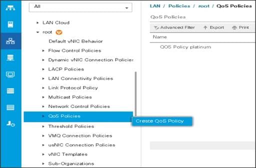
Create QoS Policies
To create the QoS policy for a given server configuration using the Cisco UCS Manager GUI, follow these steps:
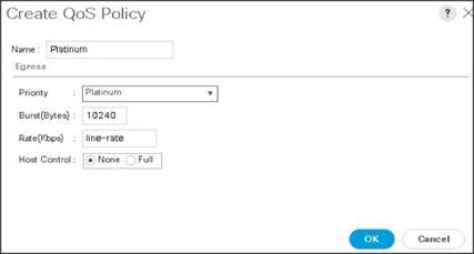
Platinum Policy
1. Select the LAN tab in the left pane in the Cisco UCS Manager GUI.
2. Select Policies > root.
3. Right-click QoS Policies.
4. Select Create QoS Policy.
5. Enter Platinum as the name of the policy.
6. Select Platinum from the drop-down list.
7. Keep the Burst(Bytes) field set to default (10240).
8. Keep the Rate(Kbps) field set to default (line-rate).
9. Keep Host Control radio button set to default (none).
10. When the pop-up window appears, click OK to complete the creation of the Policy.
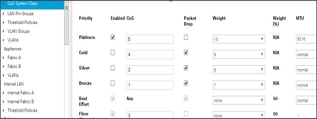
Set Jumbo Frames
To set Jumbo frames and enable QoS, follow these steps:
1. Select the LAN tab in the left pane in the Cisco UCS Manager GUI.
2. Select LAN Cloud > QoS System Class.
3. In the right pane, select the General tab
4. In the Platinum row, enter 9216 for MTU.
5. Check the Enabled Check box next to Platinum.
6. In the Best Effort row, select none for weight.
7. In the Fiber Channel row, select none for weight.
8. Click Save Changes.
9. Click OK.
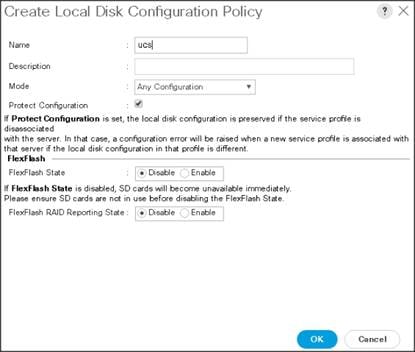
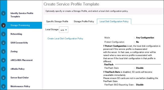
Create the Local Disk Configuration Policy
To create local disk configuration in the Cisco UCS Manager GUI, follow these steps:
1. Select the Servers tab on the left pane in the Cisco UCS Manager GUI.
2. Go to Policies > root.
3. Right-click Local Disk Config Policies.
4. Select Create Local Disk Configuration Policy.
5. Enter ucs as the local disk configuration policy name.
6. Change the Mode to Any Configuration. Check the Protect Configuration box.
7. Keep the FlexFlash State field as default (Disable).
8. Keep the FlexFlash RAID Reporting State field as default (Disable).
9. Click OK to complete the creation of the Local Disk Configuration Policy.
10. Click OK.
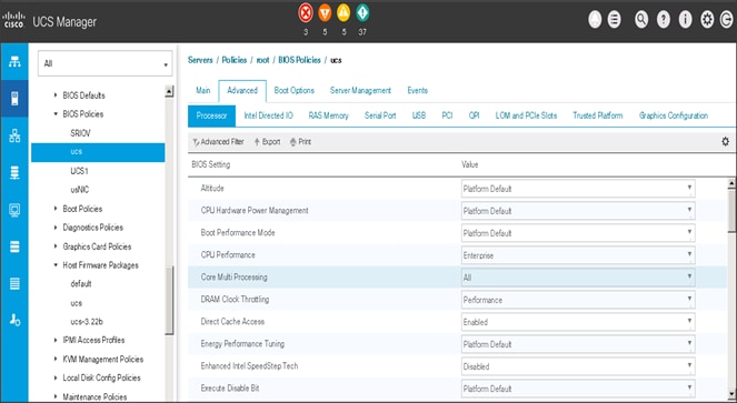
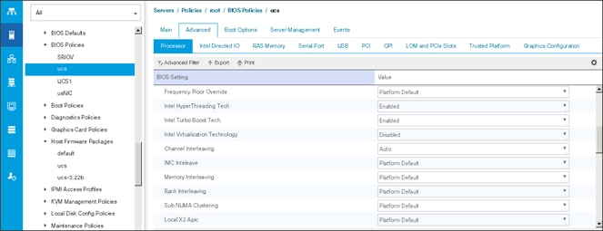
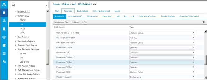
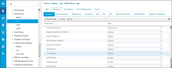
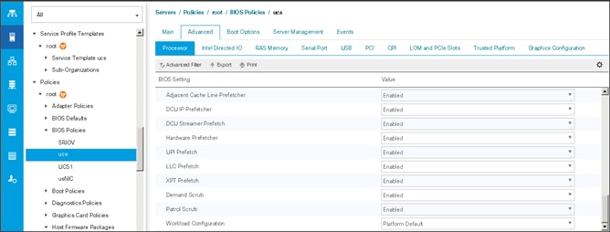
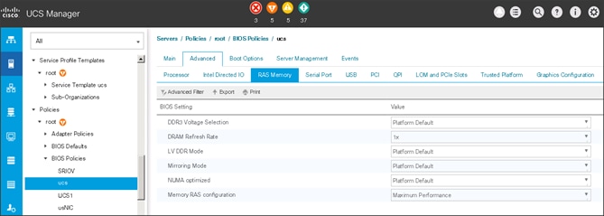
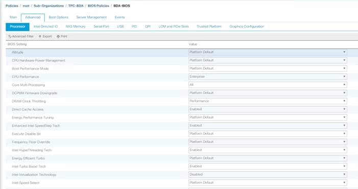
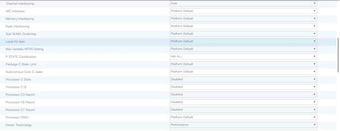
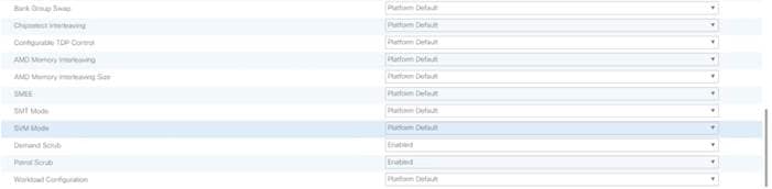
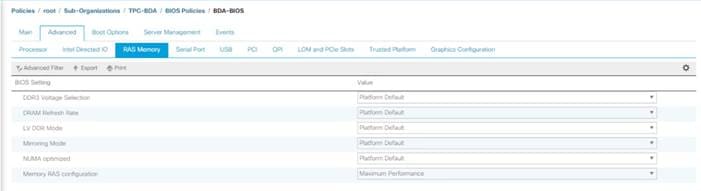
Create the Server BIOS Policy
The BIOS policy feature in Cisco UCS automates the BIOS configuration process. The traditional method of setting the BIOS is manually and is often error-prone. By creating a BIOS policy and assigning the policy to a server or group of servers, can enable transparency within the BIOS settings configuration.
![]() BIOS settings can have a significant performance impact, depending on the workload and the applications. The BIOS settings listed in this section is for configurations optimized for best performance which can be adjusted based on the application, performance, and energy efficiency requirements.
BIOS settings can have a significant performance impact, depending on the workload and the applications. The BIOS settings listed in this section is for configurations optimized for best performance which can be adjusted based on the application, performance, and energy efficiency requirements.
To create a server BIOS policy using the Cisco UCS Manager GUI, follow these steps:
1. Select the Servers tab in the left pane in the UCS Manager GUI.
2. Select Policies > root.
3. Right-click BIOS Policies.
4. Select Create BIOS Policy.
5. Enter your preferred BIOS policy name (ucs).
6. Change the BIOS settings as shown in the following figures.
7. Only changes that need to be made are in the Processor and RAS Memory settings.
Create the Boot Policy
To create boot policies within the Cisco UCS Manager GUI, follow these steps:
1. Select the Servers tab in the left pane in the UCS Manager GUI.
2. Select Policies > root.
3. Right-click the Boot Policies.
4. Select Create Boot Policy.
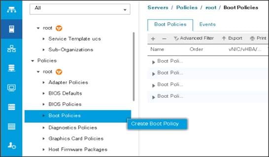
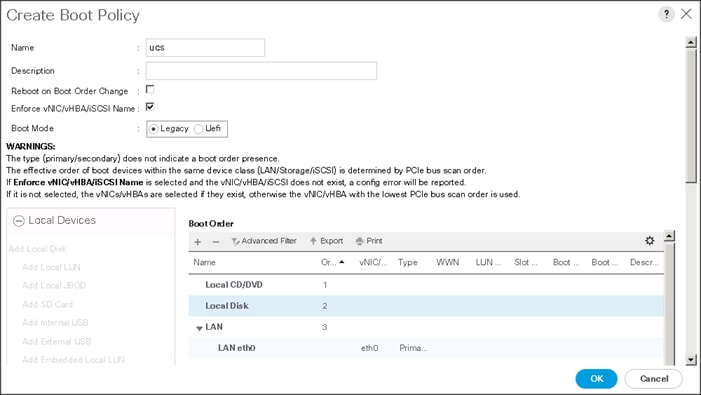
5. Enter ucs as the boot policy name.
6. (Optional) enter a description for the boot policy.
7. Keep the Reboot on Boot Order Change check box unchecked.
8. Keep Enforce vNIC/vHBA/iSCSI Name check box checked.
9. Keep Boot Mode Default (Legacy).
10. Expand Local Devices > Add CD/DVD and select Add Local CD/DVD.
11. Expand Local Devices and select Add Local Disk.
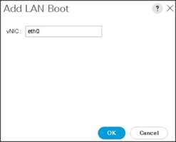
12. Expand vNICs and select Add LAN Boot and enter eth0.
13. Click OK to add the Boot Policy.
14. Click OK.
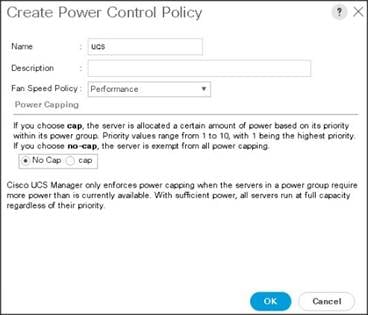
Create Power Control Policy
To create Power Control policies within the Cisco UCS Manager GUI, follow these steps:
1. Select the Servers tab in the left pane in the Cisco UCS Manager GUI.
2. Select Policies > root.
3. Right-click the Power Control Policies.
4. Select Create Power Control Policy.
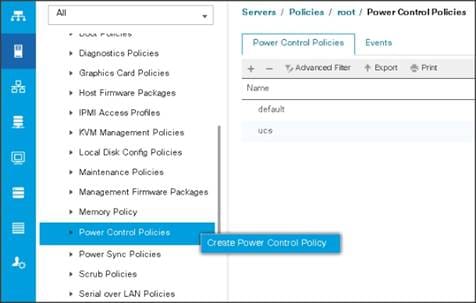
5. Enter ucs as the Power Control policy name.
6. (Optional) enter a description for the boot policy.
7. Select Performance for Fan Speed Policy.
8. Select No cap for Power Capping selection.
9. Click OK to create the Power Control Policy.
10. Click OK.
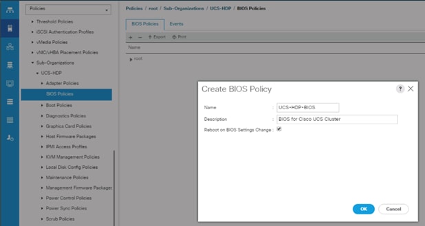
Create Server BIOS Policy
To create a server BIOS policy for the Cisco UCS environment, follow these steps:
1. In Cisco UCS Manager, click the Servers tab in the navigation pane.
2. Select Policies > root > Sub-Organization > UCS-HDP > BIOS Policies.
3. Right-click BIOS Policies.
4. Select Create BIOS Policy.
5. Enter C240M5-BIOS as the BIOS policy name.
Figure 24 BIOS Configuration

Create Service Profile Template
To create the Service Profile Template, follow these steps:
1. Select the Servers tab in the left pane in the Cisco UCS Manager GUI.
2. Right-click Service Profile Templates.
3. Select Create Service Profile Template.
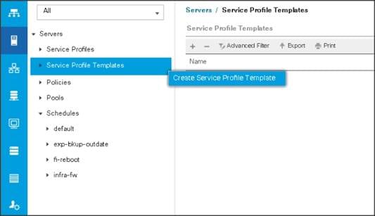
The Create Service Profile Template window appears.
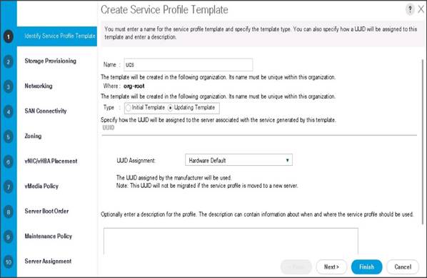
To identify the service profile template, follow these steps:
1. Name the service profile template as ucs. Select the Updating Template radio button.
2. In the UUID section, select Hardware Default as the UUID pool.
3. Click Next to continue to the next section.
Configure the Storage Provisioning for the Template
To configure storage policies, follow these steps:
1. Go to the Local Disk Configuration Policy tab and select ucs for the Local Storage.
2. Click Next to continue to the next section.
3. Click Next once the Networking window appears to go to the next section.
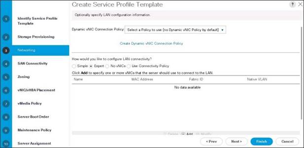
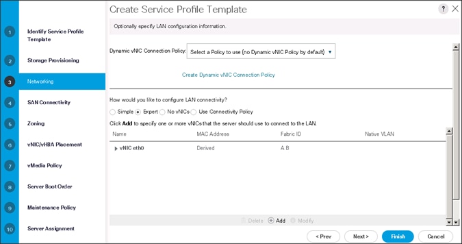
Configure Network Settings for the Template
To configure the network settings for the templates, follow these steps:
1. Keep the Dynamic vNIC Connection Policy field at the default.
2. Select Expert radio button for the option how would you like to configure LAN connectivity?
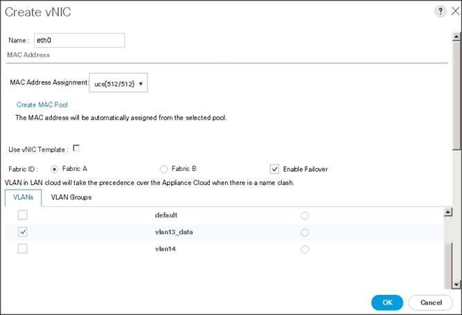
3. Click Add to add a vNIC to the template.
4. The Create vNIC window displays. Name the vNIC as eth0.
5. Select ucs in the Mac Address Assignment pool.
6. Select the Fabric A radio button and check the Enable failover check box for the Fabric ID.
7. Check the VLAN13 check box for VLANs and select the Native VLAN radio button.
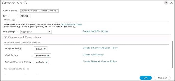
8. Select MTU size as 9000.
9. Select adapter policy as Linux.
10. Select QoS Policy as Platinum.
11. Keep the Network Control Policy as Default.
12. Click OK.
![]() Optionally, Network Bonding can be setup on the vNICs for each host for redundancy as well as for increased throughput.
Optionally, Network Bonding can be setup on the vNICs for each host for redundancy as well as for increased throughput.
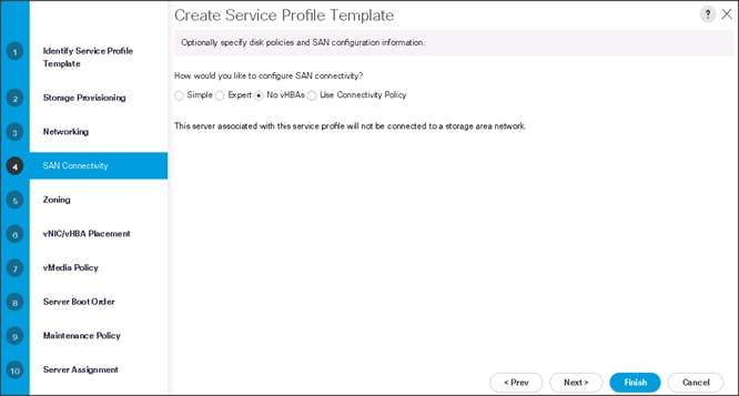
13. Click Next to continue with SAN Connectivity.
14. Select no vHBAs for How would you like to configure SAN Connectivity?
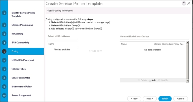
15. Click Next to continue with Zoning.
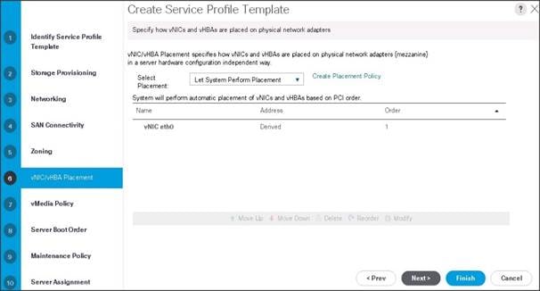
16. Click Next to continue with vNIC/vHBA placement.
17. Click Next to configure vMedia Policy.
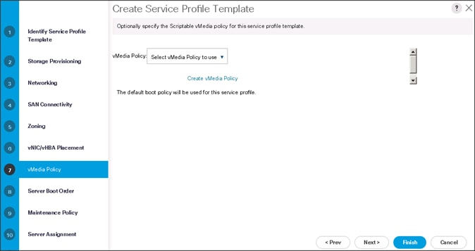
Configure the vMedia Policy for the Template
To configure the vMedia policy for the template, follow these steps:
1. Click Next once the vMedia Policy window appears to go to the next section.
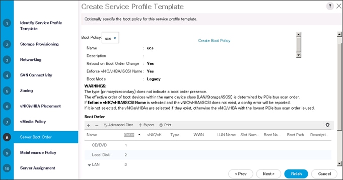
Configure the Server Boot Order for the Template
To set the boot order for the servers, follow these steps:
1. Select ucs in the Boot Policy name field.
2. Review to make sure that all of the boot devices were created and identified.
3. Verify that the boot devices are in the correct boot sequence.
4. Click OK.
5. Click Next to continue to the next section.
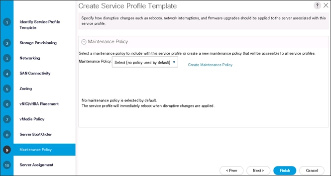
6. In the Maintenance Policy window, apply the maintenance policy.
7. Keep the Maintenance policy at no policy used by default. Click Next to continue to the next section.
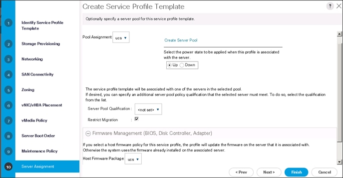
Configure the Server Assignment for the Template
To assign the servers to the pool, In the Server Assignment window, follow these steps:
1. Select ucs for the Pool Assignment field.
2. Select the power state to be Up.
3. Keep the Server Pool Qualification field set to <not set>.
4. Check the Restrict Migration check box.
5. Select ucs in Host Firmware Package.
Configure the Operational Policies for the Template
To configure the operational policies for the template, in the Operational Policies Window, follow these steps:
1. Select ucs in the BIOS Policy field.
2. Select ucs in the Power Control Policy field.
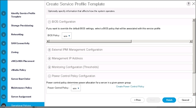
3. Click Finish to create the Service Profile template.
4. Click OK in the pop-up window to proceed.
5. Select the Servers tab in the left pane of the Cisco UCS Manager GUI.
6. Go to Service Profile Templates > root.
7. Right-click Service Profile Templates ucs.
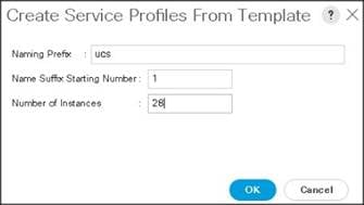
8. Select Create Service Profiles From Template.
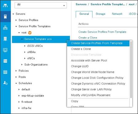
The Create Service Profiles from Template window appears.
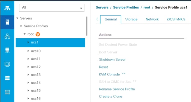
Association of the Service Profiles will take place automatically.
Install Red Hat Enterprise Linux 7.5
This section provides detailed procedures to install Red Hat Enterprise Linux 7.5 using Software RAID (OS based Mirroring) on Cisco UCS C240 M5 servers. There are multiple ways to install the Red Hat Linux operating system. The installation procedure described in this deployment guide uses the KVM console and virtual media from Cisco UCS Manager.
![]() This installation requires RHEL 7.5 DVD/ISO.
This installation requires RHEL 7.5 DVD/ISO.
To install the Red Hat Linux 7.5 operating system, follow these steps:
1. Log into the Cisco UCS 6332 Fabric Interconnect and launch the Cisco UCS Manager application.
2. Select the Equipment tab.
3. In the navigation pane expand Rack-Mounts and then Servers.
4. In the right pane, click the KVM Console >>.
5. Click OK on the KVM Console – Select IP address pop-up window.
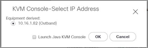
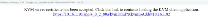
6. Click the link to launch the KVM console.
7. Point the cursor over the top right corner, select the Virtual Media tab.
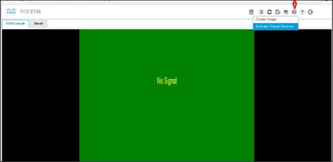
8. Click the Activate Virtual Devices found in Virtual Media tab.
9. Click the Virtual Media tab again to select CD/DVD.
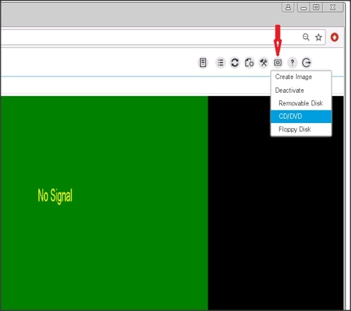
10. Select Choose File in the Virtual Disk Management windows.
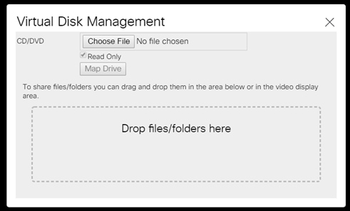
11. Browse to the Red Hat Enterprise Linux Server 7.5 installer ISO image File.
![]() The Red Hat Enterprise Linux 7.5 DVD is assumed to be on the client machine.
The Red Hat Enterprise Linux 7.5 DVD is assumed to be on the client machine.
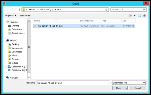
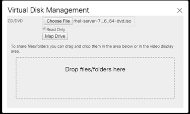
12. Click Open to add the image to the list of virtual media.
13. Click Map Drive after selecting the .iso file.
14. In the KVM window, select the KVM tab to monitor during boot.
15. In the KVM window, select the Macros > Static Macros > Ctrl-Alt-Del button in the upper left corner.
16. Click OK.
17. Click OK to reboot the system.
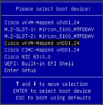
18. Press F6 key on the keyboard to select install media.
![]() Press F6 on your keyboard as soon as possible when the screen below appears to avoid the server reboot again.
Press F6 on your keyboard as soon as possible when the screen below appears to avoid the server reboot again.
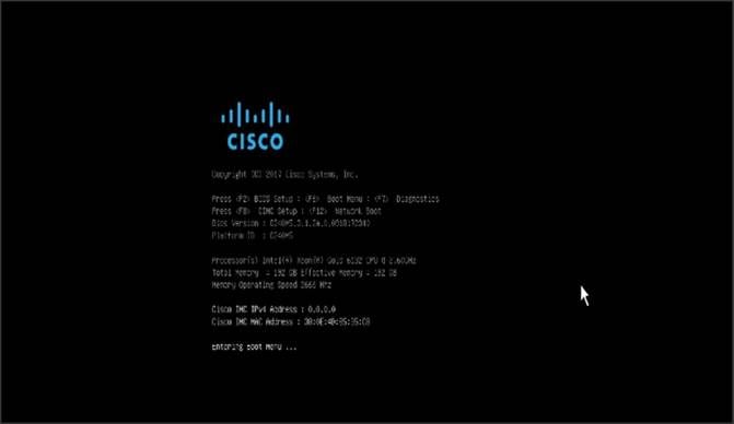
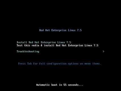
19. On reboot, the machine detects the presence of the Red Hat Enterprise Linux Server 7.5 install media.
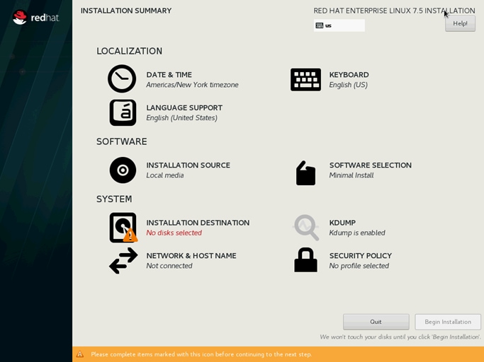
20. Select the Install Red Hat Enterprise Linux 7.5.
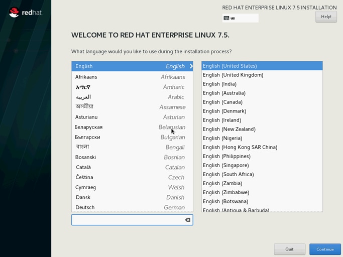
21. Skip the Media test and start the installation. Select language of installation and click Continue.
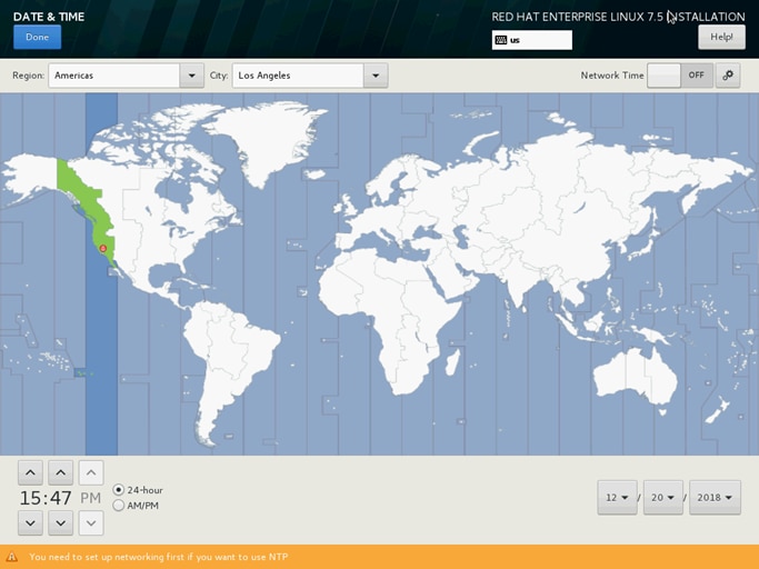
22. Select Date and time, which pops up another window as shown below:
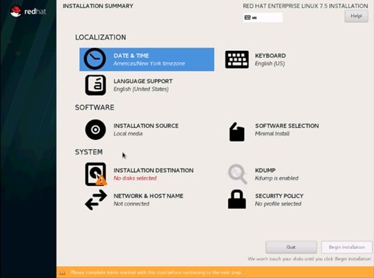
23. Select the location on the map, set the time, and click Done.
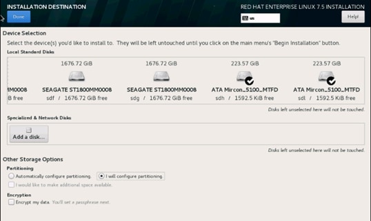
24. Click INSTALLATION DESTINATION.
25. This opens a new window with the boot disks. Make the selection and choose I will configure partitioning. Click Done.
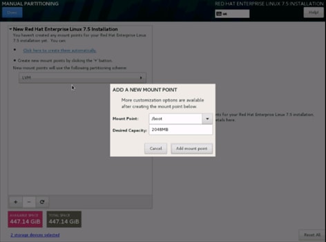
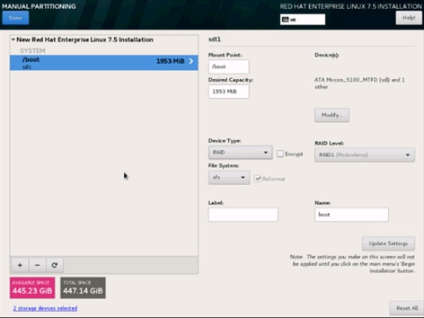
26. This opens the new window for creating the partitions. Click the + sign to add a new partition as shown below, boot partition of size 2048 MB.
27. Click Add MountPoint to add the partition.
28. Change the Device type to RAID and make sure the RAID Level is RAID1 (Redundancy) and click Update Settings to save the changes.
29. Click the + sign to create the swap partition of size 2048 MB as shown below.
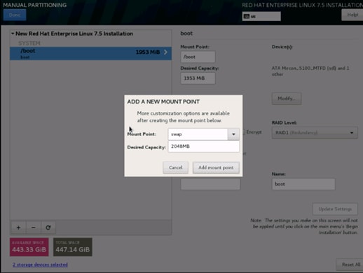
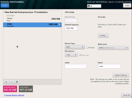
30. Change the Device type to RAID and RAID level to RAID1 (Redundancy) and click Update Settings.
31. Click + to add the / partition. The size can be left empty, so it uses the remaining capacity and click Add Mountpoint.
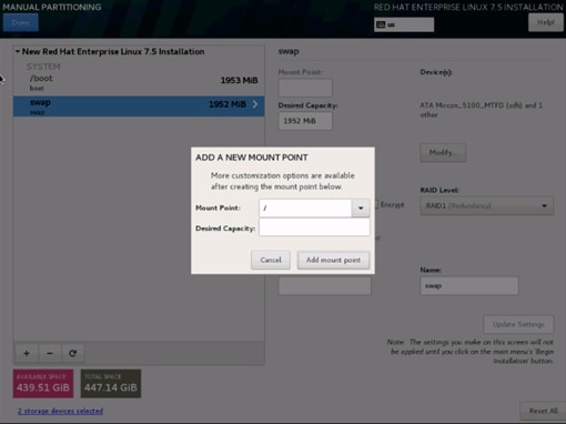
32. Change the Device type to RAID and RAID level to RAID1 (Redundancy). Click Update Settings.
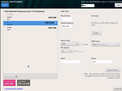
33. Click Done to return to the main screen and continue the Installation.
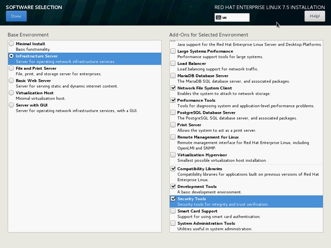
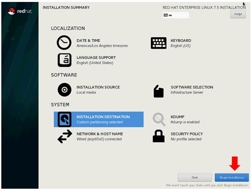
34. Click SOFTWARE SELECTION.
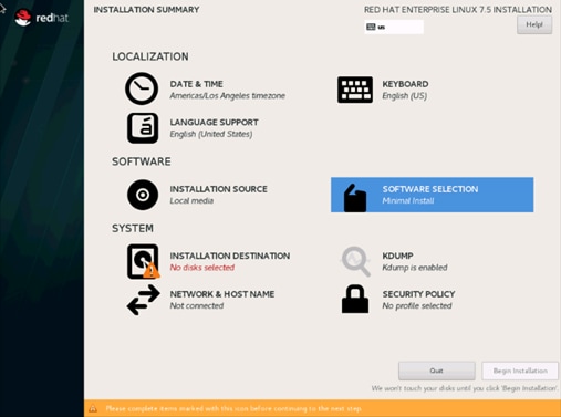
35. Select Infrastructure Server and select the Add-Ons as noted below. Click Done.
36. Click NETWORK & HOSTNAME and configure Hostname and Networking for the Host.
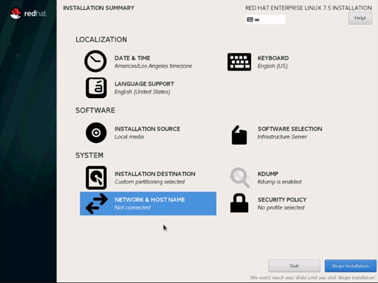
37. Type in the hostname as shown below.
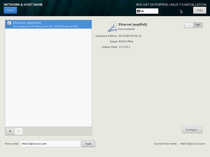
38. Click Configure to open the Network Connectivity window. Click IPV4Settings.
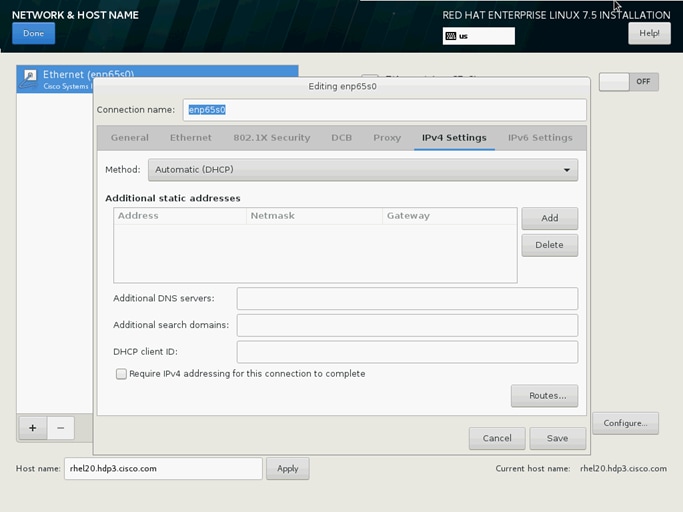
39. Change the Method to Manual and click Add to enter the IP Address, Netmask, and Gateway details.

40. Click Save and update the hostname and turn Ethernet ON. Click Done to return to the main menu.

41. Click Begin Installation on the Main menu.
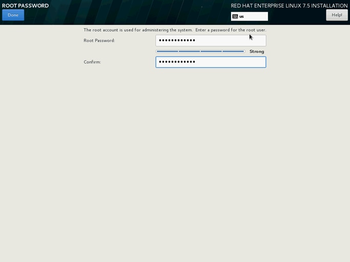
42. Select Root Password in the User Settings.
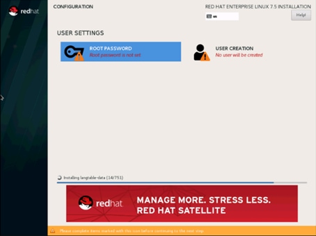
43. Enter the Root Password and click Done.
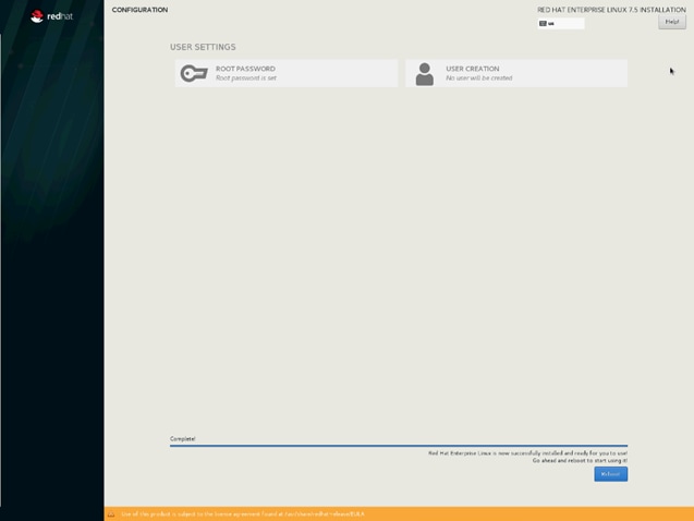
44. When the installation is complete reboot the system.
45. Repeat the steps to install Red Hat Enterprise Linux 7.5 on the remaining servers.
![]() The OS installation and configuration of the nodes that is mentioned above can be automated through PXE boot or third-party tools.
The OS installation and configuration of the nodes that is mentioned above can be automated through PXE boot or third-party tools.
The hostnames and their corresponding IP addresses are shown in Table 7.
Table 7 Hostnames and IP Addresses
| Hostname |
eth0 |
| rhel1 |
10.16.1.31 |
| rhel2 |
10.16.1.32 |
| rhel3 |
10.16.1.33 |
| rhel4 |
10.16.1.34 |
| rhel1 |
10.16.1.35 |
| rhel6 |
10.16.1.36 |
| rhel7 |
10.16.1.37 |
| rhel8 |
10.16.1.38 |
| rhel9 |
10.16.1.39 |
| rhel10 |
10.16.1.40 |
| rhel11 |
10.16.1.41 |
| rhel12 |
10.16.1.42 |
| rhel13 |
10.16.1.43 |
| rhel14 |
10.16.1.44 |
| rhel15 |
10.16.1.45 |
| rhel16 |
10.16.1.46 |
| … |
… |
| rhel24 |
10.16.1.54 |
![]() Multi-homing configuration is not recommended in this design, so please assign only one network interface on each host.
Multi-homing configuration is not recommended in this design, so please assign only one network interface on each host.
![]() For simplicity outbound NATing is configured for internet access when desired such as accessing public repos and/or accessing Red Hat Content Delivery Network. However, configuring outbound NAT is beyond the scope of this document.
For simplicity outbound NATing is configured for internet access when desired such as accessing public repos and/or accessing Red Hat Content Delivery Network. However, configuring outbound NAT is beyond the scope of this document.
Post OS Install Configuration
Choose one of the nodes of the cluster or a separate node as the Admin Node for management such as HDP installation, Ansible, creating a local Red Hat repo and so on. In this document, rhel1 has been used for this purpose.
Configure /etc/hosts
Setup /etc/hosts on the Admin node; this is a pre-configuration to setup DNS as shown in the next section.
![]() For the purpose of simplicity, /etc/hosts file is configured with hostnames in all the nodes. However, in large scale production grade deployment, DNS server setup is highly recommended. Furthermore, /etc/hosts file is not copied into containers running on the platform.
For the purpose of simplicity, /etc/hosts file is configured with hostnames in all the nodes. However, in large scale production grade deployment, DNS server setup is highly recommended. Furthermore, /etc/hosts file is not copied into containers running on the platform.
Below are the sample A records for DNS configuration within Linux environment.
$ORIGIN hdp3.cisco.com.
rhel1 A 10.16.1.31
rhel2 A 10.16.1.32
rhel3 A 10.16.1.33
…
…
rhel28 A 10.16.1.59
To create the host file on the admin node, follow these steps:
1. Log into the Admin Node (rhel1).
#ssh 10.16.1.31
2. Populate the host file with IP addresses and corresponding hostnames on the Admin node (rhel1) and other nodes as follows:
3. On Admin Node (rhel1):
# cat /etc/hosts
127.0.0.1 localhost localhost.localdomain localhost4 localhost4.localdomain4
::1 localhost localhost.localdomain localhost6 localhost6.localdomain6
10.16.1.31 rhel1 rhel1.hdp3.cisco.com
10.16.1.32 rhel2 rhel2.hdp3.cisco.com
10.16.1.33 rhel3 rhel3.hdp3.cisco.com
10.16.1.34 rhel4 rhel4.hdp3.cisco.com
10.16.1.35 rhel5 rhel5.hdp3.cisco.com
10.16.1.36 rhel6 rhel6.hdp3.cisco.com
10.16.1.37 rhel7 rhel7.hdp3.cisco.com
10.16.1.38 rhel8 rhel8.hdp3.cisco.com
10.16.1.39 rhel9 rhel9.hdp3.cisco.com
10.16.1.40 rhel10 rhel10.hdp3.cisco.com
10.16.1.41 rhel11 rhel11.hdp3.cisco.com
10.16.1.42 rhel12 rhel12.hdp3.cisco.com
10.16.1.43 rhel13 rhel13.hdp3.cisco.com
10.16.1.44 rhel14 rhel14.hdp3.cisco.com
10.16.1.45 rhel15 rhel15.hdp3.cisco.com
10.16.1.46 rhel16 rhel16.hdp3.cisco.com
10.16.1.47 rhel17 rhel17.hdp3.cisco.com
Set Up the Passwordless Login
To manage all of the clusters nodes from the admin node password-less login needs to be setup. It assists in automating common tasks with Ansible, and shell-scripts without having to use passwords.
To enable a passwordless login across all the nodes when Red Hat Linux is installed across all the nodes in the cluster, follow these steps:
1. Log into the Admin Node (rhel1).
#ssh 10.13.1.31
2. Run the ssh-keygen command to create both public and private keys on the admin node.
# ssh-keygen -N '' -f ~/.ssh/id_rsa
Figure 25 ssh-keygen
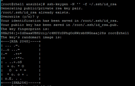
3. Run the following command from the admin node to copy the public key id_rsa.pub to all the nodes of the cluster. ssh-copy-id appends the keys to the remote-host’s .ssh/authorized_keys.
# for i in {1..17}; do echo "copying rhel$i.hdp3.cisco.com"; ssh-copy-id -i ~/.ssh/id_rsa.pub root@rhel$i.hdp3.cisco.com; done;
4. Enter yes for Are you sure you want to continue connecting (yes/no)?
5. Enter the password of the remote host.
Create the Red Hat Enterprise Linux (RHEL) 7.5 Local Repository
To create the repository using RHEL DVD or ISO on the admin node (in this deployment rhel1 is used for this purpose), create a directory with all the required RPMs, run the createrepo command and then publish the resulting repository.
1. Log into rhel1. Create a directory that would contain the repository.
# mkdir -p /var/www/html/rhelrepo
2. Copy the contents of the Red Hat DVD to /var/www/html/rhelrepo
3. Alternatively, if you have access to a Red Hat ISO Image, Copy the ISO file to rhel1.
4. Log back into rhel1 and create the mount directory.
# scp rhel-server-7.5-x86_64-dvd.iso rhel1:/root/
# mkdir -p /mnt/rheliso
# mount -t iso9660 -o loop /root/rhel-server-7.5-x86_64-dvd.iso /mnt/rheliso/
5. Copy the contents of the ISO to the /var/www/html/rhelrepo directory.
# cp -r /mnt/rheliso/* /var/www/html/rhelrepo
6. On rhel1 create a .repo file to enable the use of the yum command.
# vi /var/www/html/rhelrepo/rheliso.repo
[rhel7.5]
name=Red Hat Enterprise Linux 7.5
baseurl=http://10.16.1.31/rhelrepo
gpgcheck=0
enabled=1
7. Copy rheliso.repo file from /var/www/html/rhelrepo to /etc/yum.repos.d on rhel1.
# cp /var/www/html/rhelrepo/rheliso.repo /etc/yum.repos.d/
![]() Based on this repo file yum requires httpd to be running on rhel1 for other nodes to access the repository.
Based on this repo file yum requires httpd to be running on rhel1 for other nodes to access the repository.
8. To make use of repository files on rhel1 without httpd, edit the baseurl of repo file /etc/yum.repos.d/rheliso.repo to point repository location in the file system.
![]() This step is needed to install software on Admin Node (rhel1) using the repo (such as httpd, create-repo, etc.)
This step is needed to install software on Admin Node (rhel1) using the repo (such as httpd, create-repo, etc.)
# vi /etc/yum.repos.d/rheliso.repo
[rhel7.5]
name=Red Hat Enterprise Linux 7.5
baseurl=file:///var/www/html/rhelrepo
gpgcheck=0
enabled=1
Create the Red Hat Repository Database
To create the Red Hat repository database, follow these steps:
1. Install the createrepo package on admin node (rhel1). Use it to regenerate the repository database(s) for the local copy of the RHEL DVD contents.
# yum -y install createrepo
2. Run createrepo on the RHEL repository to create the repo database on admin node
# cd /var/www/html/rhelrepo
# createrepo .
Figure 26 createrepo
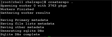
Set Up Ansible
To set up Ansible, follow these steps:
1. Download Ansible rpm from the following link:
https://releases.ansible.com/ansible/rpm/release/epel-7-x86_64/ansible-2.4.6.0-1.el7.ans.noarch.rpm
# wget https://releases.ansible.com/ansible/rpm/release/epel-7-x86_64/ansible-2.4.6.0-1.el7.ans.noarch.rpm
![]() For more information about to download and install Ansible engine, please follow the link https://access.redhat.com/articles/3174981
For more information about to download and install Ansible engine, please follow the link https://access.redhat.com/articles/3174981
2. Run the following command to install ansible.
# yum localinstall -y ansible-2.4.6.0-1.el7.ans.noarch.rpm
3. Verify Ansible installation by running the following commands.
# ansible –version
# ansible localhost -m ping
[WARNING]: provided hosts list is empty, only localhost is available. Note that the implicit localhost does not match 'all'
localhost | SUCCESS => {
"changed": false,
"failed": false,
"ping": "pong"
}
4. Prepare the host inventory file for Ansible as shown below. Various host groups have been created based on any specific installation requirements of certain hosts.
[root@rhel1 ~]# cat /etc/ansible/hosts
[admin]
rhel1.hdp3.cisco.com
[namenodes]
rhel1.hdp3.cisco.com
rhel2.hdp3.cisco.com
rhel3.hdp3.cisco.com
[datanodes]
rhel4.hdp3.cisco.com
rhel5.hdp3.cisco.com
rhel6.hdp3.cisco.com
rhel7.hdp3.cisco.com
rhel8.hdp3.cisco.com
rhel9.hdp3.cisco.com
rhel10.hdp3.cisco.com
rhel11.hdp3.cisco.com
rhel12.hdp3.cisco.com
rhel13.hdp3.cisco.com
rhel14.hdp3.cisco.com
rhel15.hdp3.cisco.com
rhel16.hdp3.cisco.com
rhel17.hdp3.cisco.com
rhel18.hdp3.cisco.com
rhel19.hdp3.cisco.com
rhel20.hdp3.cisco.com
rhel21.hdp3.cisco.com
rhel22.hdp3.cisco.com
rhel23.hdp3.cisco.com
rhel24.hdp3.cisco.com
rhel25.hdp3.cisco.com
rhel26.hdp3.cisco.com
rhel27.hdp3.cisco.com
rhel28.hdp3.cisco.com
[nodeswithgpu]
rhel25.hdp3.cisco.com
rhel26.hdp3.cisco.com
rhel27.hdp3.cisco.com
rhel28.hdp3.cisco.com
[nodes]
rhel1.hdp3.cisco.com
rhel2.hdp3.cisco.com
rhel3.hdp3.cisco.com
rhel4.hdp3.cisco.com
rhel5.hdp3.cisco.com
rhel6.hdp3.cisco.com
rhel7.hdp3.cisco.com
rhel8.hdp3.cisco.com
rhel9.hdp3.cisco.com
rhel10.hdp3.cisco.com
rhel11.hdp3.cisco.com
rhel12.hdp3.cisco.com
rhel13.hdp3.cisco.com
rhel14.hdp3.cisco.com
rhel15.hdp3.cisco.com
rhel16.hdp3.cisco.com
rhel17.hdp3.cisco.com
rhel18.hdp3.cisco.com
rhel19.hdp3.cisco.com
rhel20.hdp3.cisco.com
rhel21.hdp3.cisco.com
rhel22.hdp3.cisco.com
rhel23.hdp3.cisco.com
rhel24.hdp3.cisco.com
rhel25.hdp3.cisco.com
rhel26.hdp3.cisco.com
rhel27.hdp3.cisco.com
rhel28.hdp3.cisco.com
5. Verify host group by running the following commands. Figure 26 shows the outcome of the ping command.
# ansible nodeswithgpu -m ping
Figure 27 Ansible – Ping Hosts
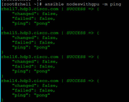
Install httpd
Setting up the RHEL repository on the admin node requires httpd. To set up RHEL repository on the admin node, follow these steps:
1. Install httpd on the admin node to host repositories:
![]() The Red Hat repository is hosted using HTTP on the admin node; this machine is accessible by all the hosts in the cluster.
The Red Hat repository is hosted using HTTP on the admin node; this machine is accessible by all the hosts in the cluster.
# yum –y install httpd
2. Add ServerName and make the necessary changes to the server configuration file:
# vi /etc/httpd/conf/httpd.conf
ServerName 10.16.1.31:80
3. Start httpd:
# service httpd start
# chkconfig httpd on
Set Up All Nodes to Use the RHEL Repository
To set up all noes to use the RHEL repository, follow these steps:
![]() Based on this repository file, yum requires httpd to be running on rhel1 for other nodes to access the repository.
Based on this repository file, yum requires httpd to be running on rhel1 for other nodes to access the repository.
1. Copy the rheliso.repo to all the nodes of the cluster:
# ansible nodes -m copy -a “src=/var/www/html/rhelrepo/rheliso.repo dest=/etc/yum.repos.d/.”
2. Copy the /etc/hosts file to all nodes:
# ansible nodes -m copy -a “src=/etc/hosts dest=/etc/hosts”
3. Purge the yum caches:
# ansible nodes -a “yum clean all”
# ansible nodes -a “yum repolist”
![]() While suggested configuration is to disable SELinux as shown below, if for any reason SELinux needs to be enabled on the cluster, then ensure to run the following to make sure that the httpd is able to read the Yum repofiles.
While suggested configuration is to disable SELinux as shown below, if for any reason SELinux needs to be enabled on the cluster, then ensure to run the following to make sure that the httpd is able to read the Yum repofiles.
Upgrade the Cisco Network Driver for VIC1387
The latest Cisco Network driver is required for performance and updates. The latest drivers can be downloaded from the link below:
https://software.cisco.com/download/home/283862063/type/283853158/release/4.0.2
In the ISO image, the required driver kmod-enic-…..rpm can be located at Network\Cisco\VIC\RHEL\RHEL7.5.
1. From a node connected to the Internet, download, extract and transfer kmod-enic-.rpm to rhel1 (admin node).
2. Copy the rpm on all nodes of the cluster using the following Ansible commands. For this example, the rpm is assumed to be in present working directory of rhel1:
[root@rhel1 ~]# ansible all -m copy -a "src=/root/kmod-enic-3.1.137.5-700.16.rhel7u5.x86_64.rpm dest=/root/."
3. Use the yum module to install the enic driver rpm file on all the nodes through Ansible:
[root@rhel1 ~]# ansible all –m yum –a “name=/root/kmod-enic-3.1.137.5-700.16.rhel7u5.x86_64.rpm state=present”
4. Make sure that the above installed version of kmod-enic driver is being used on all nodes by running the command "modinfo enic" on all nodes:
[root@rhel1 ~]# ansible all -m command -a “modinfo enic”
5. It is recommended to download the kmod-megaraid driver for higher performance. The RPM can be found in the same package at: \Linux\Storage\LSI\Cisco_Storage_12G_SAS_RAID_controller\RHEL\RHEL7.5
Install xfsprogs
From the admin node rhel1 run the command shown below to Install xfsprogs on all the nodes for xfs filesystem:
# ansible all -m yum -a “name=xfsprogs state=present”
Set Up JAVA
To setup JAVA, follow these steps:
![]() HDP 3.01 requires JAVA 8.
HDP 3.01 requires JAVA 8.
1. Download jdk-7u75-linux-x64.rpm and scp the rpm to admin node (rhel1) from the link (http://www.oracle.com/technetwork/java/javase/downloads/jdk8-downloads-2133151.html )
2. Copy JDK rpm to all nodes:
# ansible nodes -m copy -a "src=/root/jdk-8u181-linux-x64.rpm dest=/root/."
3. Extract and Install JDK on all nodes:
# ansible all -m command -a "rpm -ivh jdk-8u181-linux-x64.rpm"
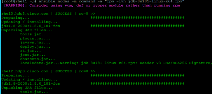
4. Create the following files java-set-alternatives.sh and java-home.sh on admin node (rhel1):
vi java-set-alternatives.sh
#!/bin/bash
for item in java javac javaws jar jps javah javap jcontrol jconsole jdb; do
rm -f /var/lib/alternatives/$item
alternatives --install /usr/bin/$item $item /usr/java/jdk1.8.0_181-amd64/bin/$item 9
alternatives --set $item /usr/java/jdk1.8.0_181-amd64/bin/$item
done
vi java-home.sh
export JAVA_HOME=/usr/java/jdk1.8.0_181-amd64
5. Make the two java scripts created above executable:
chmod 755 ./java-set-alternatives.sh ./java-home.sh
6. Copying java-set-alternatives.sh to all nodes.
ansible nodes -m copy -a “src=/root/java-set-alternatives.sh dest=/root/.”
ansible nodes -m file -a "dest=/root/java-set-alternatives.sh mode=755"
ansible nodes -m copy -a “src=/root/java-home.sh dest=/root/.”
ansible nodes -m file -a "dest=/root/java-home.sh mode=755"
7. Setup Java Alternatives
[root@rhel1 ~]# ansible all -m shell -a "/root/java-set-alternatives.sh"
8. Make sure correct java is setup on all nodes (should point to newly installed java path).
# ansible all -m shell -a "alternatives --display java | head -2"
9. Setup JAVA_HOME on all nodes.
# ansible all -m shell -a "source /root/java-home.sh"
10. Display JAVA_HOME on all nodes.
# ansible all -m command -a "echo $JAVA_HOME"
11. Display current java –version.
# ansible all -m command -a "java -version"
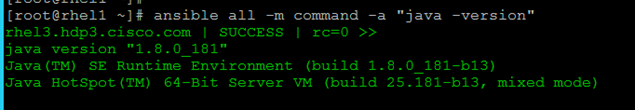
Configure NTP
The Network Time Protocol (NTP) is used to synchronize the time of all the nodes within the cluster. The Network Time Protocol daemon (ntpd) sets and maintains the system time of day in synchronism with the timeserver located in the admin node (rhel1). Configuring NTP is critical for any Hadoop Cluster. If server clocks in the cluster drift out of sync, serious problems will occur with HBase and other services.
# ansible all -m yum -a “name=ntp state=present”
![]() Installing an internal NTP server keeps your cluster synchronized even when an outside NTP server is inaccessible.
Installing an internal NTP server keeps your cluster synchronized even when an outside NTP server is inaccessible.
1. Configure /etc/ntp.conf on the admin node only with the following contents:
# vi /etc/ntp.conf
driftfile /var/lib/ntp/drift
restrict 127.0.0.1
restrict -6 ::1
server 127.127.1.0
fudge 127.127.1.0 stratum 10
includefile /etc/ntp/crypto/pw
keys /etc/ntp/keys
2. Create /root/ntp.conf on the admin node and copy it to all nodes:
# vi /root/ntp.conf
server 10.16.1.31
driftfile /var/lib/ntp/drift
restrict 127.0.0.1
restrict -6 ::1
includefile /etc/ntp/crypto/pw
keys /etc/ntp/keys
3. Copy ntp.conf file from the admin node to /etc of all the nodes by executing the following commands in the admin node (rhel1):
# ansible nodes -m copy -a “src=/root/ntp.conf dest=/etc/ntp.conf”
4. Run the following to syncronize the time and restart NTP daemon on all nodes:
# ansible all -m service -a “name=ntpd state=stopped”
# ansible all -m command -a “ntpdate rhel1.hdp3.cisco.com”
# ansible all -m service -a “name=ntpd state=started”
5. Make sure to restart of NTP daemon across reboots:
# ansible all -a "systemctl enable ntpd"
6. Verify NTP is up and running in all nodes by running the following commands:
# ansible all -a “systemctl status ntpd”
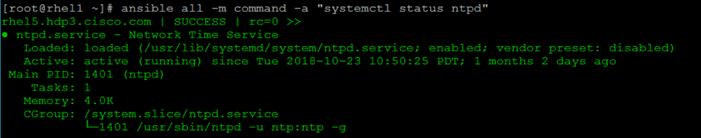
![]() Alternatively, the new Chrony service can be installed, that is quicker to synchronize clocks in mobile and virtual systems.
Alternatively, the new Chrony service can be installed, that is quicker to synchronize clocks in mobile and virtual systems.
7. Install the Chrony service:
# ansible all -m yum -a “name=chrony state=present”
8. Activate the Chrony service at boot:
# ansible all -a “systemctl enable chronyd”
9. Start the Chrony service:
# ansible all -m service -a “name=chronyd state=started”systemctl start chronyd
The Chrony configuration is in the /etc/chrony.conf file, configured similar to /etc/ntp.conf.
Enable Syslog
Syslog must be enabled on each node to preserve logs regarding killed processes or failed jobs. Modern versions such as syslog-ng and rsyslog are possible, making it more difficult to be sure that a syslog daemon is present.
One of the following commands should suffice to confirm that the service is properly configured:
# ansible all -m command -a “rsyslogd –v”
# ansible all -m command -a “service rsyslog status”
Set ulimit
On each node, ulimit -n specifies the number of inodes that can be opened simultaneously. With the default value of 1024, the system appears to be out of disk space and shows no inodes available. This value should be set to 64000 on every node.
Higher values are unlikely to result in an appreciable performance gain.
To set ulimit, follow these steps:
1. For setting the ulimit on Redhat, edit /etc/security/limits.conf on admin node rhel1 and add the following lines:
root soft nofile 64000
root hard nofile 64000

2. Copy the /etc/security/limits.conf file from admin node (rhel1) to all the nodes using the following command:
# ansible nodes -m copy -a “src=/etc/security/limits.conf dest=/etc/security/limits.conf”
3. Make sure that the /etc/pam.d/su file contains the following settings:
#%PAM-1.0
auth sufficient pam_rootOK.so
# Uncomment the following line to implicitly trust users in the "wheel" group.
#auth sufficient pam_wheel.so trust use_uid
# Uncomment the following line to require a user to be in the "wheel" group.
#auth required pam_wheel.so use_uid
auth include system-auth
account sufficient pam_succeed_if.so uid = 0 use_uid quiet
account include system-auth
password include system-auth
session include system-auth
session optional pam_xauth.so
![]() The ulimit values are applied on a new shell, running the command on a node on an earlier instance of a shell will show old values.
The ulimit values are applied on a new shell, running the command on a node on an earlier instance of a shell will show old values.
Disable SELinux
SELinux must be disabled during the install procedure and cluster setup. SELinux can be enabled after installation and while the cluster is running.
SELinux can be disabled by editing /etc/selinux/config and changing the SELINUX line to SELINUX=disabled.
To disable SELinux, follow these steps:
1. The following command will disable SELINUX on all nodes:
# ansible nodes -m shell -a "sed –i 's/SELINUX=enforcing/SELINUX=disabled/g' /etc/selinux/config"
# ansible nodes -m shell -a "setenforce 0"
![]() The command (above) may fail if SELinux is already disabled. This require reboot to take effect.
The command (above) may fail if SELinux is already disabled. This require reboot to take effect.
2. Reboot the machine, if needed for SELinux to be disabled in case it does not take effect. It can be checked using the following command:
# ansible nodes –a “sestatus”
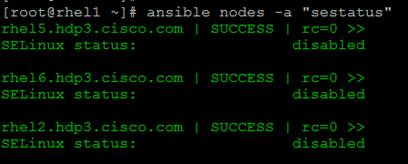
Set TCP Retries
Adjusting the tcp_retries parameter for the system network enables faster detection of failed nodes. Given the advanced networking features of UCS, this is a safe and recommended change (failures observed at the operating system layer are most likely serious rather than transitory).
To set TCP retries, follow these steps:
![]() On each node, set the number of TCP retries to 5 can help detect unreachable nodes with less latency.
On each node, set the number of TCP retries to 5 can help detect unreachable nodes with less latency.
1. Edit the file /etc/sysctl.conf and on admin node rhel1 and add the following lines:
net.ipv4.tcp_retries2=5
2. Copy the /etc/sysctl.conf file from admin node (rhel1) to all the nodes using the following command:
# ansible nodes -m copy -a “src=/etc/sysctl.conf dest=/etc/sysctl.conf”
3. Load the settings from default sysctl file /etc/sysctl.conf by running the following command:
# ansible nodes -m command -a “sysctl -p”
Disable the Linux Firewall
The default Linux firewall settings are far too restrictive for any Hadoop deployment. Since the UCS Big Data deployment will be in its own isolated network there is no need for that additional firewall.
# ansible all -m command -a "firewall-cmd --zone=public --add-port=80/tcp --permanent"
# ansible all -m command -a "firewall-cmd --reload"
# ansible all -m command -a “systemctl disable firewalld”
Disable Swapping
To disable swapping, follow these steps:
1. In order to reduce Swapping, run the following on all nodes. Variable vm.swappiness defines how often swap should be used, 60 is default:
# ansible all -m shell -a “echo 'vm.swappiness=1' >> /etc/sysctl.conf"
2. Load the settings from default sysctl file /etc/sysctl.conf and verify the content of sysctl.conf:
# ansible all -m shell -a "sysctl –p"
# ansible all -m shell -a “cat /etc/sysctl.conf”
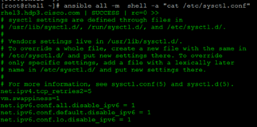
Disable Transparent Huge Pages
Disabling Transparent Huge Pages (THP) reduces elevated CPU usage caused by THP.
To disable Transparent Huge Pages, follow these steps:
1. The following commands must be run for every reboot, so copy this command to /etc/rc.local so they are executed automatically for every reboot:
# ansible all -m shell -a "echo never > /sys/kernel/mm/transparent_hugepage/enabled”
# ansible all -m shell -a "echo never > /sys/kernel/mm/transparent_hugepage/defrag"
2. On the Admin node, run the following commands:
#rm –f /root/thp_disable
#echo "echo never > /sys/kernel/mm/transparent_hugepage/enabled" >>
/root/thp_disable
#echo "echo never > /sys/kernel/mm/transparent_hugepage/defrag " >>
/root/thp_disable
3. Copy file to each node:
# ansible nodes -m copy -a “src=/root/thp_disable dest=/root/thp_disable”
4. Append the content of file thp_disable to /etc/rc.local:
# ansible nodes -m shell -a “cat /root/thp_disable >> /etc/rc.local”
Disable IPv6 Defaults
To disable IPv6 defaults, follow these steps:
1. Disable IPv6 as the addresses used are IPv4:
# ansible all -m shell -a "echo 'net.ipv6.conf.all.disable_ipv6 = 1' >> /etc/sysctl.conf"
# ansible all -m shell -a "echo 'net.ipv6.conf.default.disable_ipv6 = 1' >> /etc/sysctl.conf"
# ansible all -m shell -a "echo 'net.ipv6.conf.lo.disable_ipv6 = 1' >> /etc/sysctl.conf"
2. Load the settings from default sysctl file /etc/sysctl.conf:
# ansible all -m shell -a "sysctl –p"
Configure Data Drives on Name Node and Other Management Nodes
This section describes the steps to configure non-OS disk drives as RAID1 using the StorCli command. All drives are part of a single RAID1 volume. This volume can be used for staging any client data to be loaded to HDFS. This volume will not be used for HDFS data.
To configure data drives on Name node and other nodes, follow these steps:
1. From the website download storcli https://www.broadcom.com/support/download-search/?pg=&pf=&pn=&po=&pa=&dk=storcli.
2. Extract the zip file and copy storcli-1.14.12-1.noarch.rpm from the linux directory.
3. Download storcli and its dependencies and transfer to Admin node:
#scp storcli-1.14.12-1.noarch.rpm rhel1:/root/
4. Copy storcli rpm to all the nodes using the following commands:
# ansible all -m copy -a “src=/root/storcli-1.14.12-1.noarch.rpm dest=/root/.”
5. Run this command to install storcli on all the nodes:
# ansible all -m shell -a “rpm -ivh storcli-1.14.12-1.noarch.rpm”
6. Run this command to copy storcli64 to root directory:
# ansible all -m shell -a “cp /opt/MegaRAID/storcli/storcli64 /root/.”
7. Run this command to check the state of the disks:
# ansible all -m shell -a "./storcli64 /c0 show"
![]() If the drive state shows up as JBOD, creating RAID in the subsequent steps will fail with the error “The specified physical disk does not have the appropriate attributes to complete the requested command.”
If the drive state shows up as JBOD, creating RAID in the subsequent steps will fail with the error “The specified physical disk does not have the appropriate attributes to complete the requested command.”
8. If the drive state shows up as JBOD, it can be converted into Unconfigured Good using Cisco UCSM or storcli64 command. Following steps should be performed if the state is JBOD.
9. Get the enclosure id as follows:
ansible all -m shell -a "./storcli64 pdlist -a0 | grep Enc | grep -v 252 | awk '{print $4}' | sort | uniq -c | awk '{print $2}'"
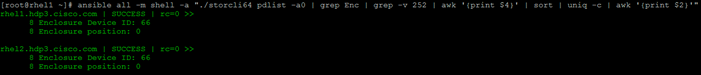
![]() It is observed that some earlier versions of storcli64 complains about above mentioned command as if it is deprecated. In this case, please ./storcli64 /c0 show all| awk '{print $1}'| sed -n '/[0-9]:[0-9]/p'|awk '{print substr($1,1,2)}'|sort -u command to determine enclosure id.
It is observed that some earlier versions of storcli64 complains about above mentioned command as if it is deprecated. In this case, please ./storcli64 /c0 show all| awk '{print $1}'| sed -n '/[0-9]:[0-9]/p'|awk '{print substr($1,1,2)}'|sort -u command to determine enclosure id.
10. Convert to unconfigured good:
ansible datanodes -m command -a "./storcli64 /c0 /e66 /sall set good force"
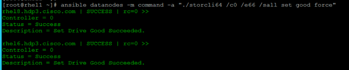
11. Verify status by running the following command:
# ansible datanodes -m command -a "./storcli64 /c0 /e66 /sall show"
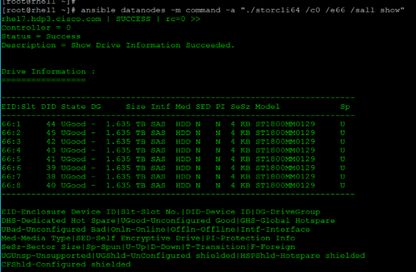
12. Run this script as root user on rhel1 to rhel3 to create the virtual drives for the management nodes:
#vi /root/raid1.sh
./storcli64 -cfgldadd r1[$1:1,$1:2,$1:3,$1:4,$1:5,$1:6,$1:7,$1:8,$1:9,$1:10,$1:11,$1:12,$1:13,$1:14,$1:15,$1:16,$1:17,$1:18,$1:19,$1:20,$1:21,$1:22,$1:23,$1:24] wb ra nocachedbadbbu strpsz1024 -a0
![]() The script (above) requires enclosure ID as a parameter.
The script (above) requires enclosure ID as a parameter.
13. Run the following command to get enclosure id:
#./storcli64 pdlist -a0 | grep Enc | grep -v 252 | awk '{print $4}' | sort | uniq -c | awk '{print $2}'
#chmod 755 raid1.sh
14. Run MegaCli script:
#./raid1.sh <EnclosureID> obtained by running the command above
WB: Write back
RA: Read Ahead
NoCachedBadBBU: Do not write cache when the BBU is bad.
Strpsz1024: Strip Size of 1024K
![]() The command (above) will not override any existing configuration. To clear and reconfigure existing configurations refer to Embedded MegaRAID Software Users Guide available: www.broadcom.com.
The command (above) will not override any existing configuration. To clear and reconfigure existing configurations refer to Embedded MegaRAID Software Users Guide available: www.broadcom.com.
15. Run the following command. State should change to Online:
ansible namenodes -m command -a "./storcli64 /c0 /e66 /sall show"
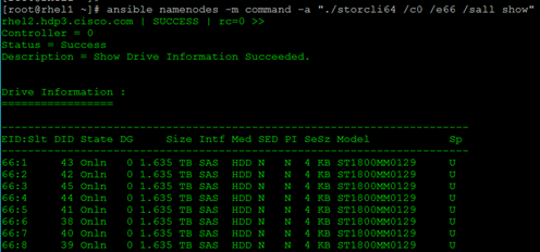
16. State can also be verified in UCSM as show below in Equipment>Rack-Mounts>Servers>Server # under Inventory/Storage/Disk tab:
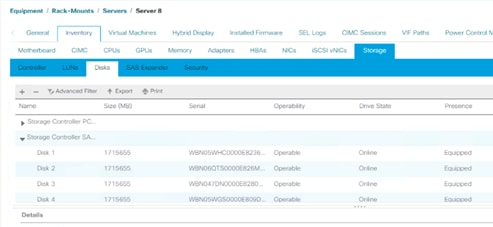
Configure Data Drives on Data Nodes
To configure non-OS disk drives as individual RAID0 volumes using StorCli command, follow these steps. These volumes will be used for HDFS Data.
1. Issue the following command from the admin node to create the virtual drives with individual RAID 0 configurations on all the data nodes:
[root@rhel1 ~]# ansible datanodes -m command -a "./storcli64 -cfgeachdskraid0 WB RA direct NoCachedBadBBU strpsz1024 -a0"
rhel7.hdp3.cisco.com | SUCCESS | rc=0 >>
Adapter 0: Created VD 0
Configured physical device at Encl-66:Slot-7.
Adapter 0: Created VD 1
Configured physical device at Encl-66:Slot-6.
Adapter 0: Created VD 2
Configured physical device at Encl-66:Slot-8.
Adapter 0: Created VD 3
Configured physical device at Encl-66:Slot-5.
Adapter 0: Created VD 4
Configured physical device at Encl-66:Slot-3.
Adapter 0: Created VD 5
Configured physical device at Encl-66:Slot-4.
Adapter 0: Created VD 6
Configured physical device at Encl-66:Slot-1.
Adapter 0: Created VD 7
Configured physical device at Encl-66:Slot-2.
…… Omitted Ouput
24 physical devices are Configured on adapter 0.
Exit Code: 0x00
![]() The command (above) will not override existing configurations. To clear and reconfigure existing configurations, refer to the Embedded MegaRAID Software Users Guide available at www.broadcom.com.
The command (above) will not override existing configurations. To clear and reconfigure existing configurations, refer to the Embedded MegaRAID Software Users Guide available at www.broadcom.com.
Configure the Filesystem for NameNodes and Datanodes
The following script formats and mounts the available volumes on each node whether it is NameNode or Data node. OS boot partition will be skipped. All drives are mounted based on their UUID as /data/disk1, /data/disk2, etc. To configure the filesystem for NameNodes and DataNodes, follow these steps:
1. From the Admin node, create partition tables and file systems on the local disks supplied to each of the nodes, run the following script as the root user on each node:
![]() The script assumes there are no partitions already existing on the data volumes. If there are partitions, delete them before running the script. This process is documented in section Delete Partitions.
The script assumes there are no partitions already existing on the data volumes. If there are partitions, delete them before running the script. This process is documented in section Delete Partitions.
#vi /root/driveconf.sh
#!/bin/bash
[[ "-x" == "${1}" ]] && set -x && set -v && shift 1
count=1
for X in /sys/class/scsi_host/host?/scan
do
echo '- - -' > ${X}
done
for X in /dev/sd?
do
list+=$(echo $X " ")
done
for X in /dev/sd??
do
list+=$(echo $X " ")
done
for X in $list
do
echo "========"
echo $X
echo "========"
if [[ -b ${X} && `/sbin/parted -s ${X} print quit|/bin/grep -c boot` -
ne 0
]]
then
echo "$X bootable - skipping."
continue
else
Y=${X##*/}1
echo "Formatting and Mounting Drive => ${X}"
166
/sbin/mkfs.xfs –f ${X}
(( $? )) && continue
#Identify UUID
UUID=`blkid ${X} | cut -d " " -f2 | cut -d "=" -f2 | sed 's/"//g'`
/bin/mkdir -p /data/disk${count}
(( $? )) && continue
echo "UUID of ${X} = ${UUID}, mounting ${X} using UUID on
/data/disk${count}"
/bin/mount -t xfs -o inode64,noatime,nobarrier -U ${UUID}
/data/disk${count}
(( $? )) && continue
echo "UUID=${UUID} /data/disk${count} xfs inode64,noatime,nobarrier 0
0" >> /etc/fstab
((count++))
fi
done
2. Run the following command to copy driveconf.sh to all the nodes:
# chmod 755 /root/driveconf.sh
# ansible datanodes -m copy -a “src=/root/driveconf.sh dest=/root/.”
# ansible nodes -m file -a "dest=/root/driveconf.sh mode=755"
3. Run the following command from the admin node to run the script across all data nodes:
# ansible datanodes -m shell -a “/root/driveconf.sh”
4. Run the following from the admin node to list the partitions and mount points:
# ansible datanodes -m shell -a “df –h”
# ansible datanodes -m shell -a “mount”
# ansible datanodes -m shell -a “cat /etc/fstab”
Delete Partitions
To delete a partition, follow these steps:
1. Run the mount command (‘mount’) to identify which drive is mounted to which device /dev/sd<?>
2. umount the drive for which partition is to be deleted and run fdisk to delete as shown below.
![]() Be sure not to delete the OS partition since this will wipe out the OS.
Be sure not to delete the OS partition since this will wipe out the OS.
# mount
# umount /data/disk1 ç (disk1 shown as example)
#(echo d; echo w;) | sudo fdisk /dev/sd<?>
Cluster Verification
This section describes the steps to create the script cluster_verification.sh that helps to verify the CPU, memory, NIC, and storage adapter settings across the cluster on all nodes. This script also checks additional prerequisites such as NTP status, SELinux status, ulimit settings, JAVA_HOME settings and JDK version, IP address and hostname resolution, Linux version and firewall settings.
To verify a cluster, follow these steps:
1. Create the script cluster_verification.sh as shown, on the Admin node (rhel1).
#vi cluster_verification.sh
#!/bin/bash
shopt -s expand_aliases,
# Setting Color codes
green='\e[0;32m'
red='\e[0;31m'
NC='\e[0m' # No Color
echo -e "${green} === Cisco UCS Integrated Infrastructure for Big Data and Analytics \ Cluster Verification === ${NC}"
echo ""
echo ""
echo -e "${green} ==== System Information ==== ${NC}"
echo ""
echo ""
echo -e "${green}System ${NC}"
ansible all -m shell -a "dmidecode |grep -A2 'System Information'"
echo ""
echo ""
echo -e "${green}BIOS ${NC}"
ansible all -m shell -a "dmidecode | grep -A3 'BIOS Information'"
echo ""
echo ""
echo -e "${green}Memory ${NC}"
ansible all -m shell -a "cat /proc/meminfo | grep -i ^memt | uniq"
echo ""
echo ""
echo -e "${green}Number of Dimms ${NC}"
ansible all -m shell -a "echo 'DIMM Slots:'; dmidecode |grep -c \ '^[[:space:]]*Locator:'"
ansible all -m shell -a "echo 'DIMM Count is:'; dmidecode |grep -c \ '^[[:space:]]*Locator:'"
ansible all -m shell -a "dmidecode | awk '/Memory Device$/,/^$/ {print}' | grep -e '^Mem' -e Size: -e Speed: -e Part | sort -u | grep -v -e 'NO \ DIMM' -e 'No Module Installed' -e Unknown"
echo ""
echo ""
# probe for cpu info #
echo -e "${green}CPU ${NC}"
ansible all -m shell -a "grep '^model name' /proc/cpuinfo | sort -u"
echo ""
ansible all -m shell -a "lscpu | grep -v -e op-mode -e ^Vendor -e family -e\ Model: -e Stepping: -e BogoMIPS -e Virtual -e ^Byte -e '^NUMA node(s)'"
echo ""
echo ""
# probe for nic info #
echo -e "${green}NIC ${NC}"
ansible all -m shell -a "ifconfig | egrep '(^e|^p)' | awk '{print \$1}' | \ xargs -l `which ethtool` | grep -e ^Settings -e Speed"
echo ""
ansible all -m shell -a "lspci | grep -i ether"
echo ""
echo ""
# probe for disk info #
echo -e "${green}Storage ${NC}"
ansible all -m shell -a "echo 'Storage Controller: '; `which lspci` | grep -i -e \ raid -e storage -e lsi"
echo ""
ansible all -m shell -a "dmesg | grep -i raid | grep -i scsi"
echo ""
ansible all -m shell -a "lsblk -id | awk '{print \$1,\$4}'|sort | nl"
echo ""
echo ""
echo -e "${green} ================ Software ======================= ${NC}"
echo ""
echo ""
echo -e "${green}Linux Release ${NC}"
ansible all -m shell -a "cat /etc/*release | uniq"
echo ""
echo ""
echo -e "${green}Linux Version ${NC}"
ansible all -m shell -a "uname -srvm | fmt"
echo ""
echo ""
echo -e "${green}Date ${NC}"
ansible all -m shell -a "date"
echo ""
echo ""
echo -e "${green}NTP Status ${NC}"
ansible all -m shell -a "ntpstat 2>&1 | head -1"
echo ""
echo ""
echo -e "${green}SELINUX ${NC}"
ansible all -m shell -a "echo -n 'SElinux status: '; grep ^SELINUX= \ /etc/selinux/config 2>&1"
echo ""
echo ""
ansible all -m shell -a "echo 'CPUspeed Service: '; service cpuspeed status 2>&1"
ansible all -m shell -a "echo 'CPUspeed Service: '; chkconfig --list cpuspeed 2>&1"
echo ""
echo ""
echo -e "${green}Java Version${NC}"
ansible all -m shell -a "java -version 2>&1; echo JAVA_HOME is ${JAVA_HOME}"
echo ""
echo ""
echo -e "${green}Hostname LoOKup${NC}"
ansible all -m shell -a "ip addr show"
echo ""
echo ""
echo -e "${green}Open File Limit${NC}"
ansible all -m shell -a "echo 'Open file limit(should be >32K): '; ulimit -n"
2. Change permissions to executable:
# chmod 755 cluster_verification.sh
3. Run the Cluster Verification tool from the admin node. This can be run before starting Hadoop to identify any discrepancies in Post OS Configuration between the servers or during troubleshooting of any cluster / Hadoop issues:
#./cluster_verification.sh
Install HDP 3.0.1
HDP is an enterprise grade, hardened Hadoop distribution. HDP combines Apache Hadoop and its related projects into a single tested and certified package. HPD 3.0.1 components are depicted in below. This section details how to install HDP 3.0.1 on the cluster.
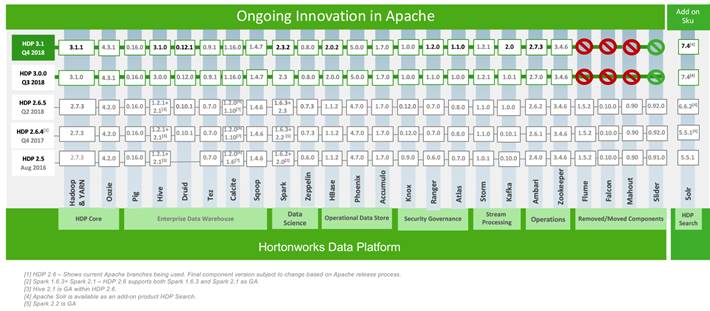
Prerequisites for HDP Installation
This section details the prerequisites for the HDP installation, such as setting up HDP repositories.
Hortonworks Repository
1. From a host connected to the Internet, create a Hortonworks folder and download the Hortonworks repositories as shown below, then transfer it to the admin node.
![]() If the admin node is connected to the internet via outbound NAT, repositories can be downloaded directly into the admin node.
If the admin node is connected to the internet via outbound NAT, repositories can be downloaded directly into the admin node.
# mkdir -p /tmp/Hortonworks/
# cd /tmp/Hortonworks
2. Download Hortonworks HDP repo:
# wget http://public-repo-1.hortonworks.com/HDP/centos7/3.x/updates/3.0.1.0/HDP-3.0.1.0-centos7-rpm.tar.gz
--2018-10-13 11:02:02-- http://public-repo-1.hortonworks.com/HDP/centos7/3.x/updates/3.0.1.0/HDP-3.0.1.0-centos7-rpm.tar.gz
Resolving public-repo-1.hortonworks.com (public-repo-1.hortonworks.com)... 13.35.121.86, 13.35.121.14, 13.35.121.127, ...
Connecting to public-repo-1.hortonworks.com (public-repo-1.hortonworks.com)|13.35.121.86|:80... connected.
HTTP request sent, awaiting response... 200 OK
ength: 8964079720 (8.3G) [application/x-tar]
Saving to: ‘HDP-3.0.1.0-centos7-rpm.tar.gz’
100%[======================================================================================================================>] 8,964,079,720 50.3MB/s in 2m 42s
2018-10-13 11:04:44 (52.9 MB/s) - ‘HDP-3.0.1.0-centos7-rpm.tar.gz’ saved [8964079720/8964079720]
3. Download Hortonworks HDP-Utils repo:
# wget http://public-repo-1.hortonworks.com/HDP-UTILS-1.1.0.22/repos/centos7/HDP-UTILS-1.1.0.22-centos7.tar.gz
--2018-10-13 11:05:30-- http://public-repo-1.hortonworks.com/HDP-UTILS-1.1.0.22/repos/centos7/HDP-UTILS-1.1.0.22-centos7.tar.gz
Resolving public-repo-1.hortonworks.com (public-repo-1.hortonworks.com)... 13.35.121.86, 13.35.121.127, 13.35.121.14, ...
Connecting to public-repo-1.hortonworks.com (public-repo-1.hortonworks.com)|13.35.121.86|:80... connected.
HTTP request sent, awaiting response... 200 OK
Length: 90606616 (86M) [application/x-tar]
Saving to: ‘HDP-UTILS-1.1.0.22-centos7.tar.gz’
100%[========================================================================================================================>] 90,606,616 45.0MB/s in 1.9s
2018-10-13 11:05:33 (45.0 MB/s) - ‘HDP-UTILS-1.1.0.22-centos7.tar.gz’ saved [90606616/90606616]
4. Download HDP-GPL repo:
# wget http://public-repo-1.hortonworks.com/HDP-GPL/centos7/3.x/updates/3.0.1.0/HDP-GPL-3.0.1.0-centos7-gpl.tar.gz
--2018-10-13 12:10:45-- http://public-repo-1.hortonworks.com/HDP-GPL/centos7/3.x/updates/3.0.1.0/HDP-GPL-3.0.1.0-centos7-gpl.tar.gz
Resolving public-repo-1.hortonworks.com (public-repo-1.hortonworks.com)... 13.35.121.120, 13.35.121.127, 13.35.121.86, ...
Connecting to public-repo-1.hortonworks.com (public-repo-1.hortonworks.com)|13.35.121.120|:80... connected.
HTTP request sent, awaiting response... 200 OK
Length: 162054 (158K) [application/x-tar]
Saving to: ‘HDP-GPL-3.0.1.0-centos7-gpl.tar.gz’
100%[=======================================================================================================================>] 162,054 --.-K/s in 0.1s
2018-10-13 12:10:45 (1.27 MB/s) - ‘HDP-GPL-3.0.1.0-centos7-gpl.tar.gz’ saved [162054/162054]
5. Download the Ambari repo:
# wget http://public-repo-1.hortonworks.com/ambari/centos7/2.x/updates/2.7.1.0/ambari-2.7.1.0-centos7.tar.gz
6. Copy the repository directory to the admin node (rhel1):
# scp -r /tmp/Hortonworks/ rhel1:/var/www/html/
7. Extract the tar ball:
[root@rhel1 Hortonworks]# tar -zxvf HDP-3.0.1.0-centos7-rpm.tar.gz
[root@rhel1 Hortonworks]# tar -zxvf HDP-UTILS-1.1.0.22-centos7.tar.gz
[root@rhel1 Hortonworks]# tar -zxvf HDP-GPL-3.0.1.0-centos7-gpl.tar.gz
[root@rhel1 Hortonworks]# tar -zxvf ambari-2.7.1.0-centos7.tar.gz
8. Create HDP repo with the following contents:
[root@rhel1]# cat /etc/yum.repos.d/hdp.repo
[HDP-3.0.1.0]
name= Hortonworks Data Platform Version - HDP-3.0.1.0
baseurl= http://rhel1.hdp3.cisco.com/Hortonworks/HDP/centos7/3.0.1.0-187
gpgcheck=0
enabled=1
priority=1
[HDP-GPL-3.0.1.0]
name=Hortonworks GPL Version - HDP-GPL-3.0.1.0
baseurl= http://rhel1.hdp3.cisco.com/Hortonworks/HDP-GPL/centos7/3.0.1.0-187
gpgcheck=0
enabled=1
priority=1
[HDP-UTILS-1.1.0.22]
name=Hortonworks Data Platform Utils Version - HDP-UTILS-1.1.0.22
baseurl= http://rhel1.hdp3.cisco.com/Hortonworks/HDP-UTILS/centos7/1.1.0.22
gpgcheck=0
enabled=1
priority=1
![]() To verify the files, go to: http://rhel1.hdp3.cisco.com/Hortonworks.
To verify the files, go to: http://rhel1.hdp3.cisco.com/Hortonworks.
vi /etc/yum.repos.d/ambari.repo
[Updates-ambari-2.7.1.0]
name=ambari-2.7.1.0 - Updates
baseurl=http://rhel1.hdp3.cisco.com/Hortonworks/ambari/centos7/2.7.1.0-169
gpgcheck=0
enabled=1
priority=1
10. From the admin node copy the repo files to /etc/yum.repos.d/ of all the nodes of the cluster:
# ansible nodes -m copy -a "src=/etc/yum.repos.d/hdp.repo dest=/etc/yum.repos.d/."
# ansible nodes -m copy -a "src=/etc/yum.repos.d/ambari.repo dest=/etc/yum.repos.d/."
Downgrade Snappy on All Nodes
Downgrade snappy on all data nodes by running this command from admin node:
# ansible all -m command -a “yum -y downgrade snappy”
HDP Installation
To install HDP, complete the following the steps:
Install and Setup Ambari Server on rhel1
1. Run the following command in rhel1 to install ambary-server:
#yum -y install ambari-server
Loaded plugins: langpacks, product-id, search-disabled-repos, subscription-manager
This system is not registered with an entitlement server. You can use subscription-manager to register.
Resolving Dependencies
--> Running transaction check
---> Package ambari-server.x86_64 0:2.7.1.0-169 will be installed
--> Processing Dependency: postgresql-server >= 8.1 for package: ambari-server-2.7.1.0-169.x86_64
--> Running transaction check
---> Package postgresql-server.x86_64 0:9.2.23-3.el7_4 will be installed
--> Processing Dependency: postgresql-libs(x86-64) = 9.2.23-3.el7_4 for package: postgresql-server-9.2.23-3.el7_4.x86_64
--> Processing Dependency: postgresql(x86-64) = 9.2.23-3.el7_4 for package: postgresql-server-9.2.23-3.el7_4.x86_64
--> Processing Dependency: libpq.so.5()(64bit) for package: postgresql-server-9.2.23-3.el7_4.x86_64
--> Running transaction check
---> Package postgresql.x86_64 0:9.2.23-3.el7_4 will be installed
---> Package postgresql-libs.x86_64 0:9.2.23-3.el7_4 will be installed
--> Finished Dependency Resolution
Dependencies Resolved
==================================================================================================================================================================
Package Arch Version Repository Size
==================================================================================================================================================================
Installing:
ambari-server x86_64 2.7.1.0-169 Updates-ambari-2.7.1.0 353 M
Installing for dependencies:
postgresql x86_64 9.2.23-3.el7_4 rhel7.5 3.0 M
postgresql-libs x86_64 9.2.23-3.el7_4 rhel7.5 234 k
postgresql-server x86_64 9.2.23-3.el7_4 rhel7.5 3.8 M
Transaction Summary
==================================================================================================================================================================
Install 1 Package (+3 Dependent packages)
Total download size: 360 M
Installed size: 452 M
Downloading packages:
(1/4): postgresql-libs-9.2.23-3.el7_4.x86_64.rpm | 234 kB 00:00:00
(2/4): postgresql-9.2.23-3.el7_4.x86_64.rpm | 3.0 MB 00:00:00
(3/4): postgresql-server-9.2.23-3.el7_4.x86_64.rpm | 3.8 MB 00:00:00
(4/4): ambari-server-2.7.1.0-169.x86_64.rpm | 353 MB 00:00:03
------------------------------------------------------------------------------------------------------------------------------------------------------------------
Total 109 MB/s | 360 MB 00:00:03
Running transaction check
Running transaction test
Transaction test succeeded
Running transaction
Installing : postgresql-libs-9.2.23-3.el7_4.x86_64 1/4
Installing : postgresql-9.2.23-3.el7_4.x86_64 2/4
Installing : postgresql-server-9.2.23-3.el7_4.x86_64 3/4
Installing : ambari-server-2.7.1.0-169.x86_64 4/4
Verifying : postgresql-9.2.23-3.el7_4.x86_64 1/4
Verifying : postgresql-libs-9.2.23-3.el7_4.x86_64 2/4
Verifying : postgresql-server-9.2.23-3.el7_4.x86_64 3/4
Verifying : ambari-server-2.7.1.0-169.x86_64 4/4
Installed:
ambari-server.x86_64 0:2.7.1.0-169
Dependency Installed:
postgresql.x86_64 0:9.2.23-3.el7_4 postgresql-libs.x86_64 0:9.2.23-3.el7_4 postgresql-server.x86_64 0:9.2.23-3.el7_4
Complete!
Install PostgreSQL in rhel2
The PostgreSQL database is used by Ambari, Hive, and Oozie services.
The rhel2 hosts the Hive and Oozie services and Ambari Server is installed on rhel1. To install, follow these steps:
1. Log into rhel2.
2. Install Red Hat Package Manager (RPM) according to the requirements of your operating system:
yum install https://yum.postgresql.org/9.6/redhat/rhel-7-x86_64/pgdg-redhat96-9.6-3.noarch.rpm
3. Install PostgreSQL version 9.5 or later:
yum install postgresql96-server postgresql96-contrib postgresql96
4. Initialize the database as shown in the below figure by running the following command:
/usr/pgsql-9.6/bin/postgresql96-setup initdb
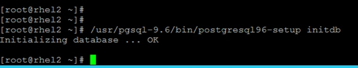
5. Start PostgreSQL:
# systemctl enable postgresql-9.6.service
# systemctl start postgresql-9.6.service
6. Open /var/lib/pgsql/9.6/data/postgresql.conf and update to the following:
listen_addresses = '*'
7. Update these files on rhel2 in the location chosen to install the databases for Hive, Oozie and Ambari, using the host ip addresses:
[root@rhel2 ~]# cat /var/lib/pgsql/9.6/data/pg_hba.conf|tail -n 20
# TYPE DATABASE USER ADDRESS METHOD
# "local" is for Unix domain socket connections only
#local all all peer
# IPv4 local connections:
#host all all 127.0.0.1/32 ident
# IPv6 local connections:
host all all ::1/128 ident
# Allow replication connections from localhost, by a user with the
# replication privilege.
#local replication postgres peer
#host replication postgres 127.0.0.1/32 ident
#host replication postgres ::1/128 ident
local all postgres peer
local all all md5
host all postgres,hive,oozie 10.16.1.32/24 md5
host all ambari 10.16.1.31/24 md5
[root@rhel2 ~]#
![]() Before adding new entries, comment the old entries as mentioned above.
Before adding new entries, comment the old entries as mentioned above.
8. Restart PostgreSQL:
# systemctl stop postgresql-9.6.service
# systemctl start postgresql-9.6.service
9. Run the following:
sudo -u postgres psql
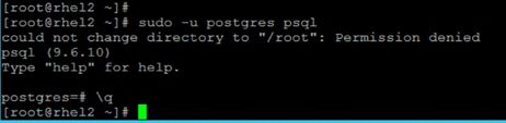
![]() For more information about setting up PostgreSQL, go to: https://docs.hortonworks.com/HDPDocuments/Ambari-2.7.1.0/bk_ambari-installation/content/install-postgres.html
For more information about setting up PostgreSQL, go to: https://docs.hortonworks.com/HDPDocuments/Ambari-2.7.1.0/bk_ambari-installation/content/install-postgres.html
Create Database for Ambari
To create the database for Ambari, follow these steps:
1. Run the following commands mentioned below in bold to create and prepare database for Ambari:
[root@rhel2 ~]# sudo -u postgres psql
could not change directory to "/root": Permission denied
psql (9.6.10)
Type "help" for help.
postgres=# \dt
No relations found.
postgres=#
postgres=#
postgres=# create database ambari;
CREATE DATABASE
postgres=# create user ambari with password 'bigdata';
CREATE ROLE
postgres=# grant all privileges on database ambari to ambari;
GRANT
postgres=# \connect ambari;
You are now connected to database "ambari" as user "postgres".
ambari=# create schema ambari authorization ambari;
CREATE SCHEMA
ambari=# alter schema ambari owner to ambari;
ALTER SCHEMA
ambari=# alter role ambari set search_path to 'ambari', 'public';
ALTER ROLE
ambari=# \q
2. Restart PostgreSQL:
[[root@rhel2 ~]# systemctl restart postgresql-9.6.service
3. Verify the ambari user by logging into psql:
# psql -U ambari -d ambari
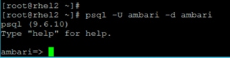
4. Load the Ambari Server database schema:
![]() Pre-load the Ambari database schema into your PostgreSQL database using the schema script.
Pre-load the Ambari database schema into your PostgreSQL database using the schema script.
5. Find the Ambari-DDL-Postgres-CREATE.sql file in the /var/lib/ambari-server/resources/ directory of the Ambari Server host after you have installed Ambari Server.
6. Copy /var/lib/ambari-server/resources/ from rhel1 to rhel2:/tmp/.
[root@rhel1 ~]# scp -r /var/lib/ambari-server/resources/* rhel2:/tmp/
7. Run the following command to launch the Ambari-DDL-Postgres-CREATE.sql script:
[root@rhel2 tmp]# cd /tmp
[root@rhel2 tmp]# psql -U ambari -d ambari
Password for user ambari:
psql (9.6.10)
Type "help" for help.
ambari=> \i Ambari-DDL-Postgres-CREATE.sql
CREATE TABLE
CREATE TABLE
CREATE TABLE
…… OUTPUT OMITTED ----
8. Check the table is created by running \dt command:
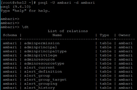
9. Restart PostgreSQL:
[root@rhel2 ~]# systemctl restart postgresql-9.6.service
Create Database for Hive
Run the following command as shown in bold to create and prepare database for Hive:
[root@rhel2 ~]# sudo -u postgres psql
could not change directory to "/root": Permission denied
psql (9.6.10)
Type "help" for help.
postgres=# create database hive;
CREATE DATABASE
postgres=# create user hive with password 'bigdata';
CREATE ROLE
postgres=# grant all privileges on database hive to hive;
GRANT
postgres=# \q
[root@rhel2 ~]#
Create Database for Oozie
Run the following command to create and prepare database for Oozie:
[root@rhel2 ~]# sudo -u postgres psql
could not change directory to "/root": Permission denied
psql (9.6.10)
Type "help" for help.
postgres=# create database oozie;
CREATE DATABASE
postgres=# create user oozie with password 'bigdata';
CREATE ROLE
postgres=# grant all privileges on database oozie to oozie;
GRANT
postgres=# \q
[root@rhel2 ~]#
Setup Ambari Server On Admin Node(Rhel1)
To setup the Ambari server, follow these steps:
1. Install the PostgreSQL JDBC driver:
[root@rhel1 2.7.1.0-169]# yum -y install postgresql-jdbc*
Loaded plugins: langpacks, product-id, search-disabled-repos, subscription-manager
This system is not registered with an entitlement server. You can use subscription-manager to register.
Resolving Dependencies
--> Running transaction check
---> Package postgresql-jdbc.noarch 0:9.2.1002-5.el7 will be installed
--> Processing Dependency: jpackage-utils for package: postgresql-jdbc-9.2.1002-5.el7.noarch
--> Processing Dependency: java for package: postgresql-jdbc-9.2.1002-5.el7.noarch
--> Running transaction check
---> Package java-1.8.0-openjdk.x86_64 1:1.8.0.161-2.b14.el7 will be installed
2. Configure Ambari server to use the JDBC driver for connectivity to Ambari database in PostgreSQL:
[root@rhel1 2.7.1.0-169]# ambari-server setup --jdbc-db=postgres --jdbc-driver=/usr/share/java/postgresql-jdbc.jar
Using python /usr/bin/python
Setup ambari-server
Copying /usr/share/java/postgresql-jdbc.jar to /var/lib/ambari-server/resources/postgresql-jdbc.jar
If you are updating existing jdbc driver jar for postgres with postgresql-jdbc.jar. Please remove the old driver jar, from all hosts. Restarting services that need the driver, will automatically copy the new jar to the hosts.
JDBC driver was successfully initialized.
Ambari Server 'setup' completed successfully.
3. Setup Ambari Server by running the following command:
[root@rhel1 ~]# ambari-server setup -j $JAVA_HOME
Using python /usr/bin/python
Setup ambari-server
Checking SELinux...
SELinux status is 'disabled'
Customize user account for ambari-server daemon [y/n] (n)? n
Adjusting ambari-server permissions and ownership...
Checking firewall status...
Checking JDK...
WARNING: JAVA_HOME /usr/java/jdk1.8.0_181-amd64 must be valid on ALL hosts
WARNING: JCE Policy files are required for configuring Kerberos security. If you plan to use Kerberos,please make sure JCE Unlimited Strength Jurisdiction Policy Files are valid on all hosts.
Check JDK version for Ambari Server...
JDK version found: 8
Minimum JDK version is 8 for Ambari. Skipping to setup different JDK for Ambari Server.
Checking GPL software agreement...
GPL License for LZO: https://www.gnu.org/licenses/old-licenses/gpl-2.0.en.html
Enable Ambari Server to download and install GPL Licensed LZO packages [y/n] (n)? y
Completing setup...
Configuring database...
Enter advanced database configuration [y/n] (n)? y
Configuring database...
==============================================================================
Choose one of the following options:
[1] - PostgreSQL (Embedded)
[2] - Oracle
[3] - MySQL / MariaDB
[4] - PostgreSQL
[5] - Microsoft SQL Server (Tech Preview)
[6] - SQL Anywhere
[7] - BDB
==============================================================================
Enter choice (4):
Hostname (rhel2.hdp3.cisco.com):
Port (5432):
Database name (ambari):
Postgres schema (ambari):
Username (ambari):
Enter Database Password (bigdata):
Configuring ambari database...
Configuring remote database connection properties...
WARNING: Before starting Ambari Server, you must run the following DDL against the database to create the schema: /var/lib/ambari-server/resources/Ambari-DDL-Postgres-CREATE.sql
Proceed with configuring remote database connection properties [y/n] (y)? y
Extracting system views...
.....
Adjusting ambari-server permissions and ownership...
Ambari Server 'setup' completed successfully.
4. Start the Ambari Server:
[root@rhel1 ~]# ambari-server start
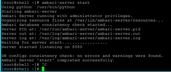
5. To check status of Ambari Server, run the following command:
# ambari-server status
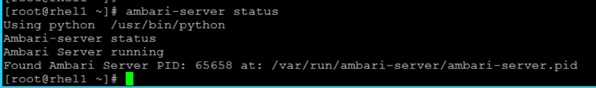
Launch the Ambari Server
When the Ambari service starts, access the Ambari Install Wizard through the browser. To launch the Ambari server, follow these steps:
1. Point the browser to http://<ip address for rhel1>:8080 or http://rhel1.hdp3.cisco.com:8080
The Ambari Login screen opens.
2. Log into the Ambari Server using the default username/password: admin/admin. This can be changed at a later period of time.
3. When logged in the “Welcome to Apache Ambari” window opens.
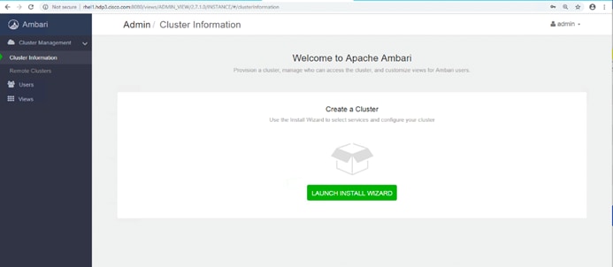
Create the Cluster
To create the cluster, follow these steps:
1. To create a cluster click “LAUNCH INSTALL WIZARD.”
2. From the Get started page type “Cisco_HDP” for the name for the cluster.
3. Click Next.
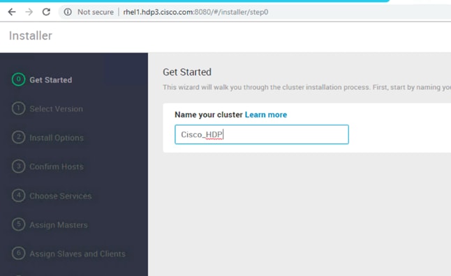
Select Version
To select the version, follow these steps:
1. In the Select Version section, choose the HDP 3.0.1.0 version.
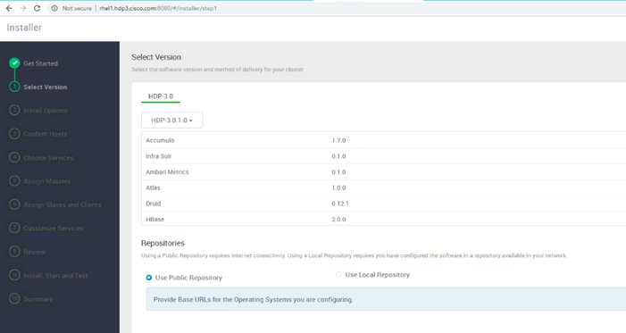
2. Under Repositories, select “Use Local Repository.”
3. Update the Redhat 7 HDP-3.0 URL to http://rhel1.hdp3.cisco.com/Hortonworks/HDP/centos7/3.0.1.0-187/
4. Update the Redhat 7 HDP-3.0-GPL URL to http://rhel1.hdp3.cisco.com/Hortonworks/HDP-GPL/centos7/3.0.1.0-187/
5. Update the Redhat 7 HDP-UTILS-1.1.0.22 to http://rhel1.hdp3.cisco.com/Hortonworks/HDP-UTILS/centos7/1.1.0.22/

![]() Make sure there are no trailing spaces after the URLs.
Make sure there are no trailing spaces after the URLs.
Select Hosts
To build up the cluster, you need to provide the general information about how you want to set up the cluster. This requires providing the Fully Qualified Domain Name (FQDN) of each of the hosts. You also need to provide access to the private key file that was created in Set Up Password-less SSH; this is used to locate all the hosts in the system and to access and interact with them securely.
1. Use the Target Hosts text box to enter the list of host names, one per line. Ranges inside brackets can also be used to indicate larger sets of hosts.
2. Select the option Provide your SSH Private Key in the Ambari cluster install wizard.
3. Copy the contents of the file /root/.ssh/id_rsa on rhel1 and paste it in the text area provided by the Ambari cluster install wizard.
![]() Make sure there is no extra white space after the text-----END RSA PRIVATE KEY-----
Make sure there is no extra white space after the text-----END RSA PRIVATE KEY-----
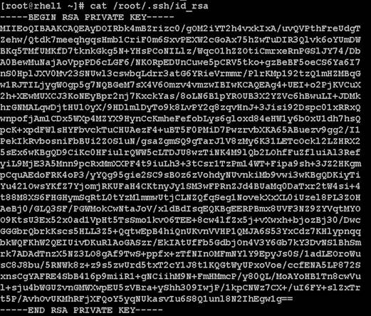
4. Click the Register and Confirm to continue.
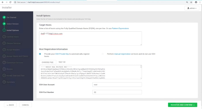
Hostname Pattern Expressions
1. Click OK in the Host Name Pattern Expressions popup.
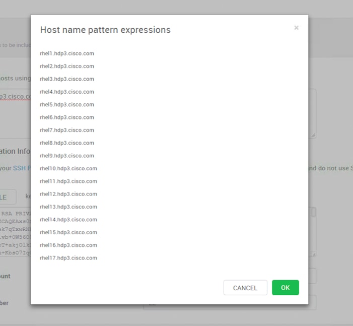
Confirm Hosts
Confirm Hosts helps ensure that Ambari has located the correct hosts for the cluster and checks those hosts to make sure they have the correct directories, packages, and processes to continue the install.
To confirm host, follow these steps:
1. If any host was selected in error, remove it by selecting the appropriate checkboxes and clicking the grey Remove Selected button.
2. To remove a single host, click the small white Remove button in the Action column.
3. When the list of hosts is confirmed, click Next.
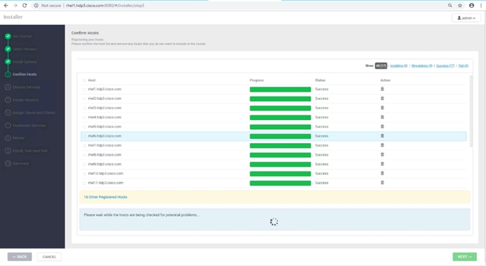
Choose Services
HDP is made up of a number of components. Go to Hortonworks Understand the Basics for more information.
To choose services, follow these steps:
1. Select all to preselect all items.
2. When you have made your selections, click Next.
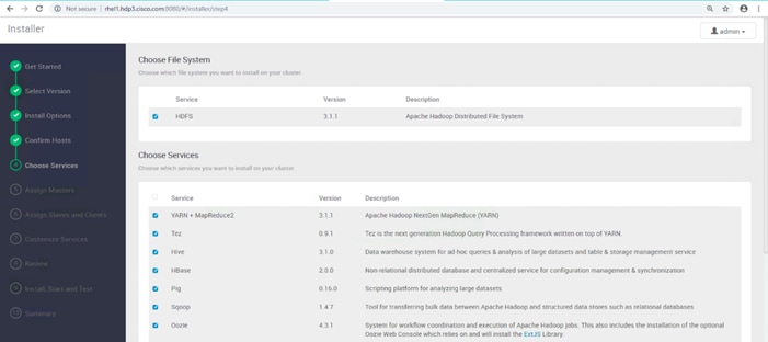
Assign Masters
The Ambari installation wizard attempts to assign the master nodes for various services that have been selected to appropriate hosts in the cluster, as listed in Table 8. The right column shows the current service assignments by host, with the hostname and its number of CPU cores and amount of RAM indicated.
1. Reconfigure the service assignments to match Table 8 shown below.
Table 8 Reconfigure the service assignments
| Service Name |
Host |
| NameNode |
rhel1, rhel3 (HA) |
| SNameNode |
rhel2 |
| History Server |
rhel2 |
| App Timeline Server |
rhel2 |
| Resource Manager |
rhel2, rhel3 (HA) |
| Hive Metastore |
rhel2 |
| WebHCat Server |
rhel2 |
| HiveServer2 |
rhel2 |
| HBase Master |
rhel2 |
| Oozie Server |
rhel1 |
| Zookeeper |
rhel1, rhel2, rhel3 |
| Spark History Server |
rhel2 |
| SmartSense HST Server |
rhel1 |
| Grafana |
rhel1 |
| Atlas Metadata Server |
rhel2 |
| Metrics Collector |
rhel1 |
2. Click Next.
Assign Slaves and Clients
The Ambari install wizard attempts to assign the slave components (DataNodes, NFSGateway, NodeManager, RegionServers, Supervisor, and Client) to appropriate hosts in the cluster.
To assign slaves and clients, follow these steps:
1. Reconfigure the service assignment to match the values shown in Table 9.
2. Assign DataNode, NodeManager, RegionServer, and Supervisor on nodes rhel3- rhel28.
3. Assign Client to all nodes.
4. Click Next.
Table 9 Services and Hostnames
| Client Service Name |
Host |
| DataNode |
rhel4-rhel28 |
| NFSGateway |
rhel1 |
| NodeManager |
rhel4-rhel28 |
| RegionServer |
rhel4-rhel28 |
| Supervisor |
rhel4-rhel28 |
| Client |
All nodes, rhel1-rhel28 |
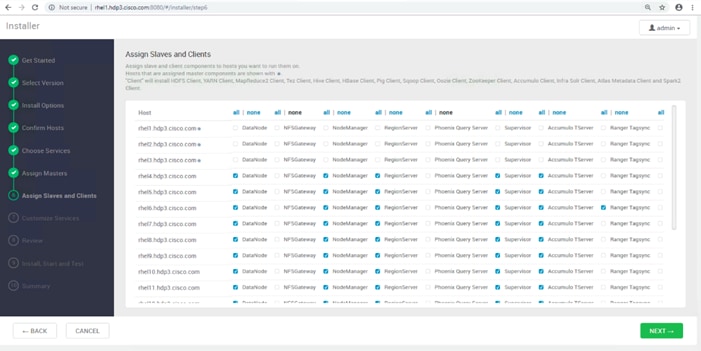
Customize Services
This section shows the tabs that manage configuration settings for Hadoop components. The wizard attempts to set reasonable defaults for each of the options here, but this can be modified to meet specific requirements. The following sections provide configuration guidance that should be refined to meet specific use case requirements.
The following changes need to be made:
· Memory and service level settings for each component and service level tuning.
· Customize the log locations of all the components to make sure growing logs do not cause the SSDs to run out of space.
Credentials
Specify the credentials as per your organizational policies for services in CREDENTIALS tab as shown below.
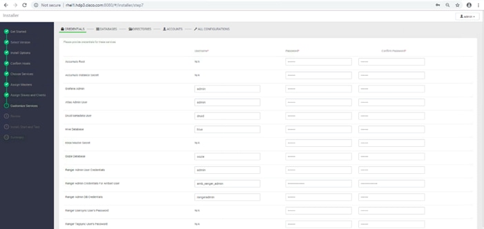
Databases
In the DATABASES tab, to configure the database for DRUID, HIVE, OOZIE, and RANGER, follow these steps:
1. Configure DRUID as shown below.
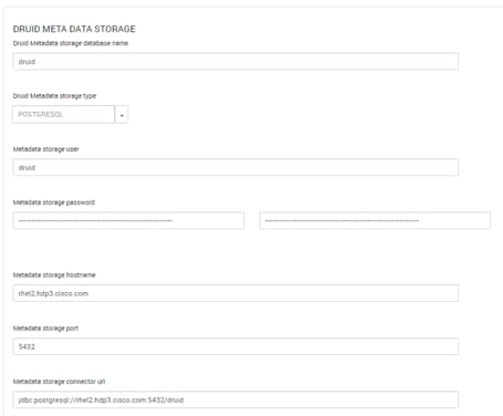
2. Change the default log location by finding the Log Dir property and modifying the /var prefix to /data/disk1.
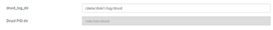
3. Configure HIVE:
a. Select Existing PostgreSQL database in the Hive Database drop-down list.
b. Enter Database Name as hive
c. Enter Database Username as hive
d. Enter Database URL as jdbc:postgresql://rhel2.hdp3.cisco.com/hive
e. Enter Database password (use the password created during hive database setup in earlier steps; for example, bigdata)
f. Click TEST CONNECTION to verify the connectivity
g. In Advanced tab, Change the default log location by filtering the Log Dir property and modifying the /var prefix to /data/disk1.
h. Change the WebHCat log directory by filtering the Log Dir property and modifying the /var prefix to /data/disk1.
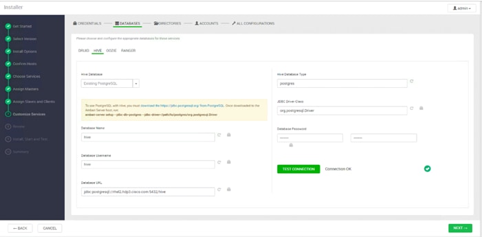
4. Configure OOZIE:
a. Select Existing PostgreSQL database in the Hive Database drop-down list.
b. Enter Database Name as oozie.
c. Enter Database Username as oozie.
d. Enter Database URL as jdbc:postgresql://rhel2.hdp3.cisco.com/oozie.
e. Enter Database password (use the password created during hive database setup in earlier steps; for example, bigdata).
f. Click TEST CONNECTION to verify the connectivity.
g. In Advanced tab, Change the default log location by filtering the Log Dir property and modifying the /var prefix to /data/disk1.
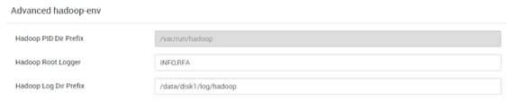

5. Configure RANGER:
a. Select POSTGRES from DB FLAVOR drop-down list.
b. Provide a Ranger DB name. For example, ranger.
c. Provide Ranger DB Username such as rangeradmin.
d. Enter JDBC connect string for a Ranger Database as jdbc:postgresql//rhel2.dhp3.cisco.com:54323/ranger.
e. Ranger DB Host as rhel2.hdp3.cisco.com.
f. Enter Ranger DB password. (Ranger database is not previously created. provide password string that would be configured in the DB. For example, bigdata).
g. Select “Yes” for Setup Database and Database User.
h. Enter “postgres” in Database Administrator (DBA) username.
i. Enter Database Administrator (DBA) password.
j. Enter jdbc:postgresql://rhel2.hdp3.cisco.com:5432/postgres in JDBC connect string for root user.
k. Update Ranger Admin Log Dir from /var to /data/disk1.
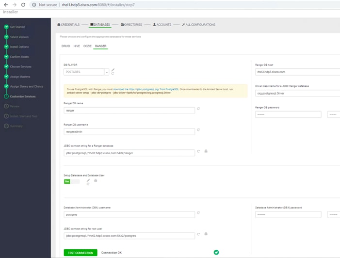
HDFS
1. In Ambari, select the HDFS Service tab and use the “Search” box to filter for the properties mentioned in Table 10 and update their values.
2. Update the following HDFS configurations in Ambari.
Table 10 HDFS Configurations in Ambari
| Property Name |
Value |
| NameNode Java Heap Size |
4096 |
| Hadoop maximum Java heap size |
4096 |
| DataNode maximum Java heap size |
4096 |
| Datanode failed disk toleration |
5 |
3. Change the default log location by filtering the Log Dir property and modifying the /var prefix to /data/disk1.
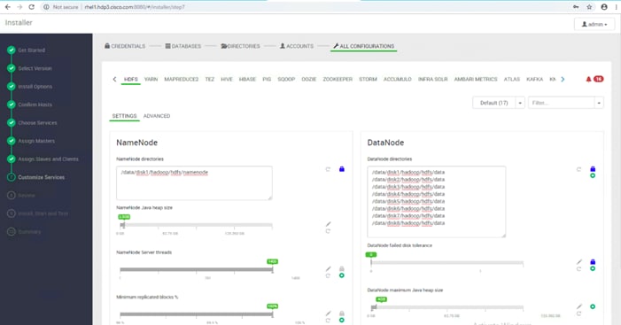
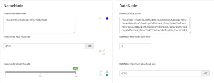
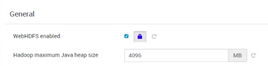
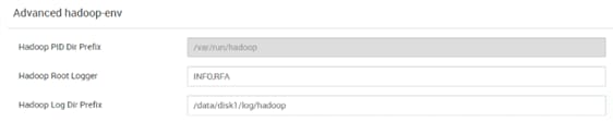
MapReduce2
1. In Ambari, choose the MapReduce Service tab and update the values as shown below.
2. Under the MapReduce2 tab, change the default log location by finding the Log Dir property and modifying the /var prefix to /data/disk1.
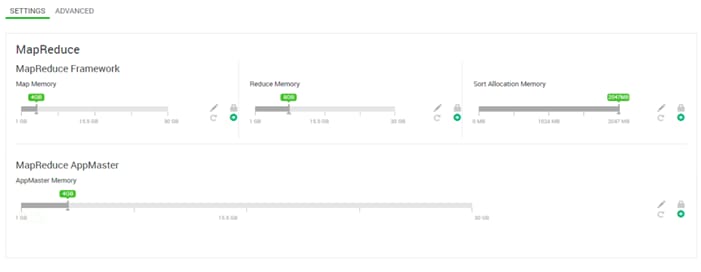
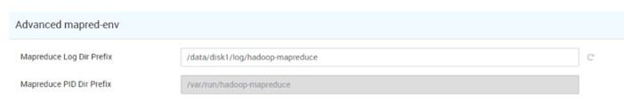
YARN
1. In Ambari, select the YARN Service, and update the following as shown in Table 11.
| Property Name |
Value |
| ResourceManager Java heap size |
4096 |
| NodeManager Java heap size |
2048 |
| YARN Java heap size |
4096 |
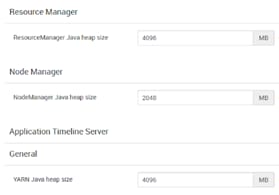
2. Under YARN tab, change the default log location by filtering the Log Dir property and modifying the /var prefix to /data/disk1.

![]() YARN requires other configurations such as config group, node labeling, enabling docker runtime, CPU/GPU scheduling and isolation, and so on, which can be found in section High Availability for HDFS NameNode and YARN ResourceManager.
YARN requires other configurations such as config group, node labeling, enabling docker runtime, CPU/GPU scheduling and isolation, and so on, which can be found in section High Availability for HDFS NameNode and YARN ResourceManager.
![]() High availability for NameNode and YARN Resource Manager can be configured using Ambari or also on non-Ambari clusters. This deployment guide covers the configuration of high availability using Ambari – Use the Ambari wizard interface to configure HA of the components.
High availability for NameNode and YARN Resource Manager can be configured using Ambari or also on non-Ambari clusters. This deployment guide covers the configuration of high availability using Ambari – Use the Ambari wizard interface to configure HA of the components.
HBase
Under the HBase tab, change the default log location by finding the Log Dir property and modifying the /var prefix to /data/disk1.
![]()
Zookeeper
Under the Zookeeper tab, change the default log location by filtering the Log Dir property and modifying the /var prefix to /data/disk1.
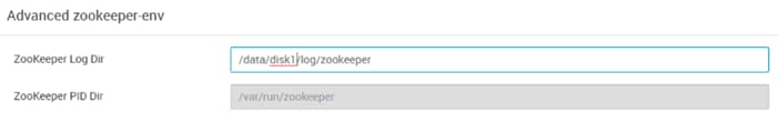
Storm
Under the Storm tab, change the default log location by finding the Log Dir property and modifying the /var prefix to /data/disk1.
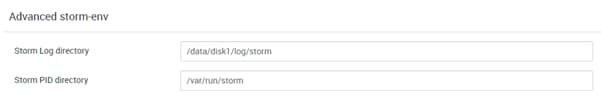
Ambari Metrics
1. Choose the Ambari Metrics Service and expand the General tab and make the changes shown below.
2. Enter the Grafana Admin password as per organizational policy.
3. Change the default log location for Metrics Collector, Metrics Monitor and Metrics Grafana by finding the Log Dir property and modifying the /var prefix to /data/disk1.
4. Change the default data dir location for Metrics Grafana by finding the data Dir property and modifying the /var prefix to /data/disk1.
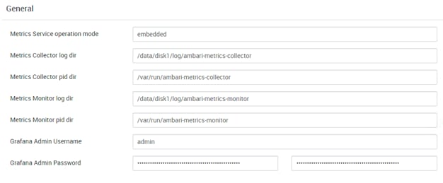
Accumulo
Select Accumulo Service and change the default log location by finding the Log Dir property and modifying the /var prefix to /data/disk1.

Atlas
Under the Atlas tab, change the default log location by finding the Log Dir property and modifying the /var prefix to /data/disk1.
Kafka
Under the Kafka tab, change the default log location by finding the Log Dir property and modifying the /var prefix to /data/disk1.
Knox
1. Select the Knox Service tab and expand the Knox gateway tab and make the changes shown below.
2. Enter the Knox Master Secret password as per organizational policy.
3. For Knox, change the gateway port to 8444 to ensure no conflicts with local HTTP server.

SmartSense
The SmartSense account requires the Hortonworks support subscription. Subscribers can populate the properties as shown below.
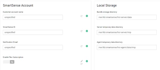
Spark
Select the Spark tab, change the default log location by finding the Log Dir property and modifying the /var prefix to /data/disk1.
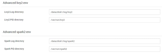
Review
The assignments that have been made are displayed. Check to make sure all is correct before clicking the Deploy button. If any changes are necessary, use the left navigation bar to return to the appropriate screen.
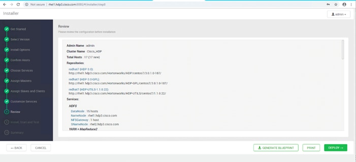
Deploy
When the review is complete, click the DEPLOY button.
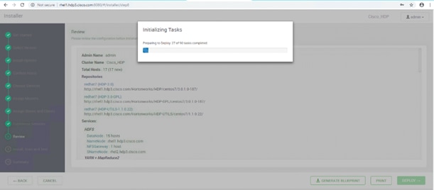
Follow the installation process. Watch for warnings and failure by clicking on the link as shown below.
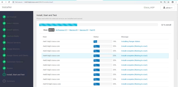
Summary of the Installation Process
On the Summary page click “COMPLETE.”
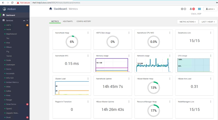
High Availability for HDFS NameNode and YARN ResourceManager
High availability for NameNode and YARN Resource Manager can be configured using Ambari or also on non-Ambari clusters. This deployment guide covers the configuration of high availability using Ambari – Use the Ambari wizard interface to configure HA of the components.
The Ambari web UI provides a wizard-driven user experience that allows to configure high availability of the components in many Hortonworks Data Platform (HDP) stack services. The high availability of the components are achieved by setting up primary and secondary components. In the event that the primary component fails or becomes unresponsive, services failover to secondary component. After configuring the high availability for a service, Ambari enables you to manage and disable (roll back) the high availability of components within that service.
Configure the HDFS NameNode High Availability
The HDFS NameNode high availability feature enables you to run redundant NameNodes in the same cluster in an Active/Passive configuration with a hot standby. This eliminates the NameNode as a potential single point of failure (SPOF) in an HDFS cluster. With the release of Hadoop 3.0, you can configure more than one backup NameNode.
Prior to the release of Hadoop 2.0, the NameNode represented a single point of failure (SPOF) in an HDFS cluster. Each cluster had a single NameNode, and if that machine or process became unavailable, the cluster as a whole would be unavailable until the NameNode was either restarted or brought up on a separate machine. This situation impacted the total availability of the HDFS cluster in two major ways:
· In the case of an unplanned event such as a machine crash, the cluster would be unavailable until an operator restarted the NameNode.
· Planned maintenance events such as software or hardware upgrades on the NameNode machine would result in periods of cluster downtime.
HDFS NameNode HA avoids this by facilitating either a fast failover to one or more backup NameNodes during machine crash, or a graceful administrator-initiated failover during planned maintenance.
![]() Secondary NameNode is not required in high availability configuration because the Standby node also performs the tasks of the Secondary NameNode.
Secondary NameNode is not required in high availability configuration because the Standby node also performs the tasks of the Secondary NameNode.
Active NameNode honors all the client requests and the Standby NameNode acts as a backup. The Standby NameNode keeps its state synchronized with Active NameNode through a group of JournalNodes(JNs). When the Active node performs any namespace modification, the Active node durably logs a modification record to a majority of these JNs. The Standby node reads the edits from the JNs and continuously watches the JNs for changes to the edit log.
Prerequisites for NameNode High Availability
The following are the prerequisites for NameNode high availability:
· NameNode Machine: Hardware for Active and Standby node should be exactly identical.
· JournalNodes Machine: JournalNode daemon is relatively lightweight, therefore it can be co-located on machines with other Hadoop daemons; it is typically located on the management nodes.
· There MUST be at least three JournalNodes, because the edit log modifications must be written to a majority of JNs. This allows the system tolerate failure of a single machine. You may also run more than three JournalNodes, but in order to increase the number of failures that the system can tolerate, you must run an odd number of JNs (3, 5, 7, and so on).
· ZooKeeper Machines: For automatic failover capability, an existing Zookeeper cluster must exist. The Zookeeper service can also co-exist with other Hadoop daemons.
· In HA Cluster, the Standby NameNode also performs the checkpoints of the namespace state, therefore do not deploy a Secondary NameNode, CheckpointNode, or BackupNode in an high availability cluster.
Deploy the NameNode High Availability Cluster
To deploy the NameNode high availability on a Ambari managed cluster, follow these steps:
![]() High availability cannot accept HDFS cluster names that include underscore (_).
High availability cannot accept HDFS cluster names that include underscore (_).
1. Log into Ambari. Click HDFS > CONFIGS. Click the ACTIONS drop-down list and click Enable NameNode HA to launch the wizard.
Figure 29 Enable NameNode HA
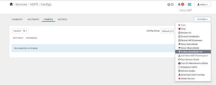
2. Step 1 launches the Enable NameNode HA wizard. On the Get Started page, specify the Nameservice ID as shown below. Click Next.
Figure 30 Enable NameNode HA Wizard – Get Started
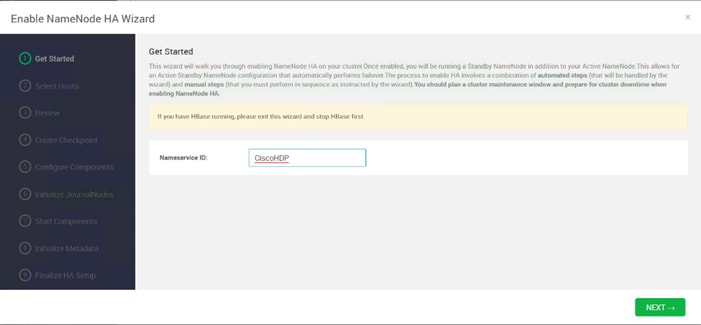
3. On the Select Hosts page, select the Additional NameNode and JournalNode. Click Next.
Figure 31 Enable NameNode HA Wizard – Select Hosts
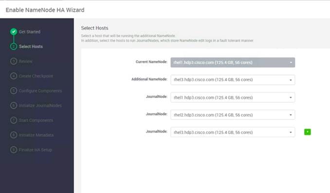
4. On the Review page, confirm the selection. To change any values, click Back, or to continue click Next.
Figure 32 Enable NameNode HA Wizard – Review
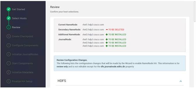
5. Create a checkpoint on the NameNode on the linux server (rhel1.hdp3.cisco.com) as shown below.
Figure 33 Enable NameNode HA Wizard – Create Checkpoint
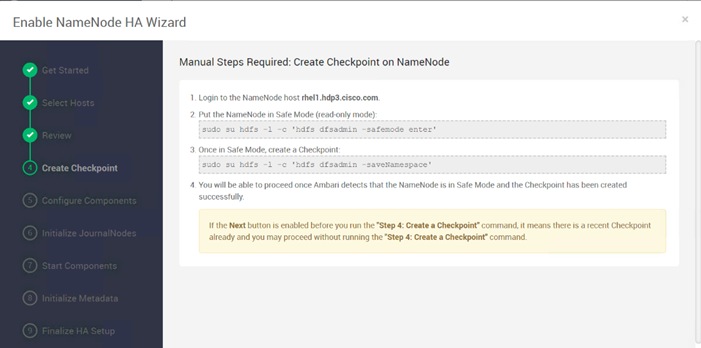
6. SSH to current NameNode, rhel1.hdp3.cisco.com and run the following commands:
[root@rhel1 ~]# sudo su hdfs -l -c 'hdfs dfsadmin -safemode enter'
Safe mode is ON
[root@rhel1 ~]# sudo su hdfs -l -c 'hdfs dfsadmin -saveNamespace'
Save namespace successful
[root@rhel1 ~]#
Figure 34 Current NameNode – Safe Mode and Create Checkpoint Command
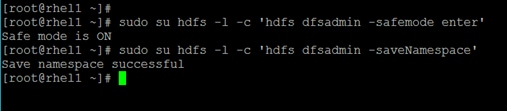
7. Return to the Ambari web UI, verify that the Checkpoint was created. Click Next.
8. See the progress bar on the Configure Components page. When the configuration steps are completed, click Next.
Figure 35 Enable NameNode HA Wizard – Configure Components
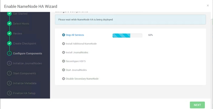
9. Initialize the JournalNodes as shown below.
Figure 36 Enable NameNode HA Wizard – Initialize JournalNodes
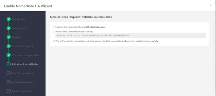
10. SSH to the current NameNode, for example rhel1.hdp3.cisco.com.
11. Run the following command:
[root@rhel1 ~]# sudo su hdfs -l -c 'hdfs namenode -initializeSharedEdits'
Figure 37 Initialize JournalNodes
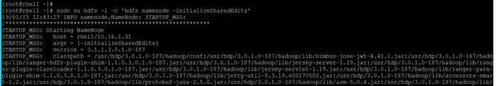
12. Return to the Ambari UI, when Ambari detects success, click Next.
13. On the Start Components page, when completed, click Next.
Figure 38 Enable NameNode HA Wizard – Start Components
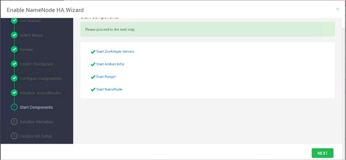
14. On the Initialize Metadata page, add the information as shown below.
Figure 39 Enable NameNode HA Wizard – Initialize Metadata
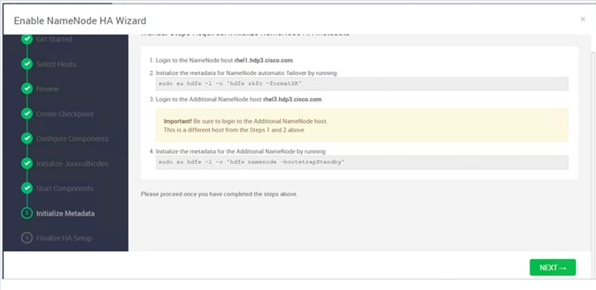
15. SSH to rhel1.hdp3.cisco.com and run the following command:
[root@rhel1 ~]# sudo su hdfs -l -c 'hdfs zkfc -formatZK'
Figure 40 Initialize the Metadata for NameNode

16. SSH to an additional NameNode, for example, rhel3.hdp3.cisco.com and run the following command:
[root@rhel3 ~]# sudo su hdfs -l -c 'hdfs namenode -bootstrapStandby'
Figure 41 Initialize the Metadata for Additional NameNode
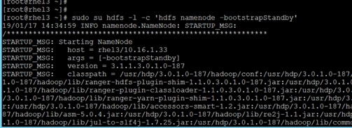
17. Return to the Ambari web UI, click NEXT. Click OK on the confirmation pop-up window. Make sure the initialization of metadata was performed in NameNode and an additional NameNode as mentioned in step 15 and 16.
Figure 42 Enable NameNode HA Wizard – Confirmation for Initialize the Metadata
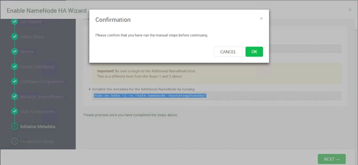
18. On the Finalize HA Setup page, you can see the progress bar as the high availability completes.
Figure 43 Enable NameNode HA Wizard – Finalize High Availability Setup
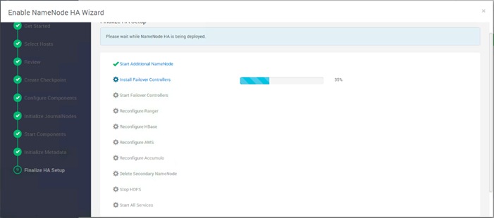
19. Click COMPLETE when done.
20. Click HDFS > SUMMARY tab, verify the Active and Standby NameNode. The Quick Links pane also shows that rhel1.hdp3.cisco.com is running the Active NameNode and rhel3.hdp3.cisco.com is running in Standby NameNode.
Figure 44 Ambari – HDFS – Summary Information
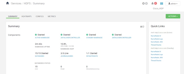
Configure the YARN ResourceManger HA
This section provides instructions on setting up the ResourceManager (RM) HA feature in a HDFS cluster. The Active and Standby ResourceManagers embed the ZooKeeper based ActiveStandbyElector to determine which RM should be active.
Prerequisites for ResourceManager HA
· The servers where Active and Standby RMs are run should have identical hardware.
· For automated failover configurations, there must be an existing Zookeeper cluster available. The ZooKeeper service nodes can be co-located with the other Hadoop daemons.
![]() At least three ZooKeeper servers must be running.
At least three ZooKeeper servers must be running.
Deploy the ResourceManager HA
ResourceManager HA can be configured manually or through Ambari. These instructions are based on configuring ResourceManager HA using Ambari.
To setup ResourceManager HA, follow these steps:
1. From the Ambari web UI, click Services > YARN. Click the ACTIONS drop-down list and select Enable ResourceManager HA.
Figure 45 Services/YARN - Enable ResourceManger HA
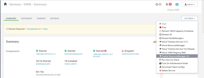
2. This launches the ResourceManager HA wizard as shown below. Click NEXT.
Figure 46 Enable ResourceManager HA Wizard – Get Started
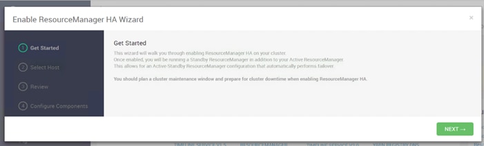
3. From the Select Host page, select the host for Additional Resource Manager. Click NEXT.
Figure 47 Enable ResourceManger HA Wizard – Select Host
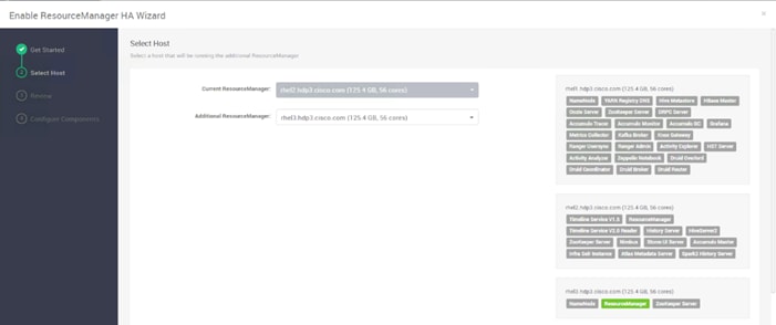
4. Proceed to the Review page.
Figure 48 Enable ResourceManager HA Wizard - Review
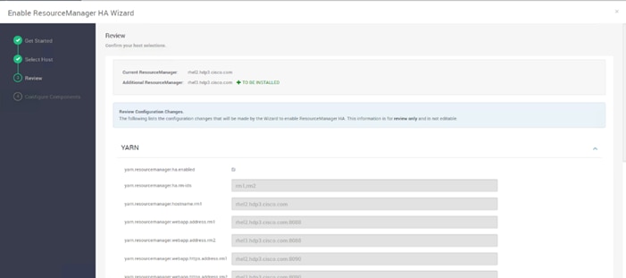
5. The Configure Components page shows the progress bar as the Additional ResourceManager is being deployed.
Figure 49 Enable ResourceManager HA Wizard – Configure Components
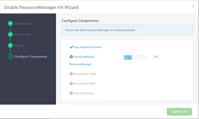
6. Click COMPLETE when done.
![]() It was observed that in certain circumstances, services might fail to restart. Click COMPLETE and restart the services in Ambari dashboard.
It was observed that in certain circumstances, services might fail to restart. Click COMPLETE and restart the services in Ambari dashboard.
7. Verify the ResourceManger HA setup by clicking Services > YARN > SUMMARY tab. The Quick Links pane identifies Active and Standby ResourceManager.
Figure 50 Services/YARN/Summary – Verify ResourceManger HA
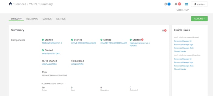
HDP Post OS Deployment – Enable GPU Isolation and Scheduling
One of the prerequisites for HDP to enable GPU isolation and scheduling, is CUDA. CUDA itself also has prerequisites. The order of installation is as follows:
· Install CUDA prerequisites
· CUDA
![]() This CVD incorporates Cisco UCS C480 ML M5 with 8 V100 GPUs; the following steps detail how to enable GPU as a Hadoop resource.
This CVD incorporates Cisco UCS C480 ML M5 with 8 V100 GPUs; the following steps detail how to enable GPU as a Hadoop resource.
· Cisco UCS C480 ML M5 resource inventory as seen through Cisco UCS Manager
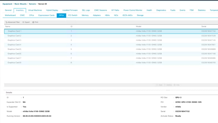
Install the Prerequisites for CUDA
To install the prerequisites for CUDA, follow these steps:
![]() Details to install CUDA can be found here: http://docs.nvidia.com/cuda/cuda-installation-guide-linux/index.html.
Details to install CUDA can be found here: http://docs.nvidia.com/cuda/cuda-installation-guide-linux/index.html.
![]() These commands are run as root or sudo.
These commands are run as root or sudo.
1. List GPUs and CPUs installed:
[root@rhel1 ~]# ansible nodeswithgpu -m shell -a "lspci | grep -i nvidia"
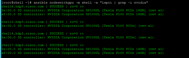
[root@rhel1 ~]# ansible nodeswithgpu -m shell -a "lscpu"
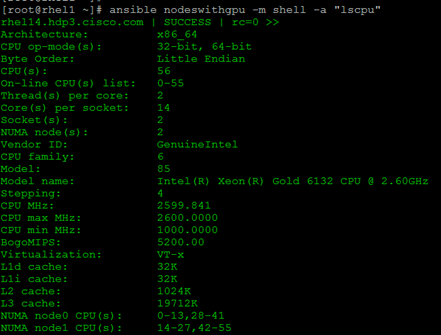
Install GCC
To install GCC, follow these steps:
1. Make sure gcc is installed in the system:
[root@rhel1 ~]# ansible nodeswithgpu -m shell -a "gcc --version"
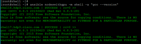
Install Kernel Headers and Installation Packages
The CUDA Driver requires that the kernel headers and development packages for the running version of the kernel are installed at the time of the driver installation, as well as whenever the driver is rebuilt. For example, if your system is running kernel version 3.17.4-301, the 3.17.4-301 kernel headers and development packages must also be installed.
ansible nodeswithgpu -m shell -a "uname -r"
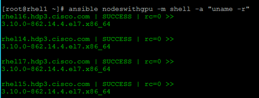
[root@rhel1 ~]# ansible nodeswithgpu -m yum -a "name=kernel-devel-$(uname -r) state=present"
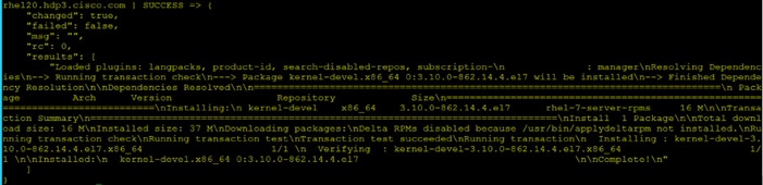
[root@rhel1 ~]# ansible nodeswithgpu -m yum -a "name=kernel-headers-$(uname -r) state=present"
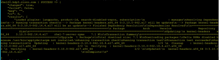
Install DKMS
The NVIDIA driver RPM packages depend on other external packages, such as DKMS. Those packages are only available on third-party repositories, such as EPEL.
To install DKMS, follow these steps:
http://rpmfind.net/linux/rpm2html/search.php?query=dkms for RHEL 7.x
RHEL 7.x http://rpmfind.net/linux/epel/7/x86_64/Packages/d/dkms-2.6.1-1.el7.noarch.rpm
1. Copy dkms rpm to all the GPU servers:
[root@rhel1 ~]# ansible nodeswithgpu -m copy -a "src=/root/dkms-2.6.1-1.el7.noarch.rpm dest=/root/."
2. Install dkms with yum install:
[root@rhel1 ~]# ansible nodeswithgpu -m command -a "yum install -y /root/dkms-2.6.1-1.el7.noarch.rpm"
Install NVIDIA GPU Drivers
To install the NVIDIA GPU drivers, follow these steps:
1. Download this NVIDIA GPU driver from http://www.nvidia.com/Download/index.asp?lang=en-us
2. For the NVIDIA driver download, select the product type, Series, Product, OS, and CUDA toolkit.
![]() For this deployment, select 9.2 for CUDA Toolkit.
For this deployment, select 9.2 for CUDA Toolkit.
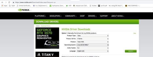
3. Click SEARCH. The selected driver is shown below.
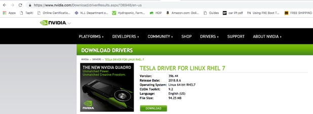
4. Click DOWNLOAD. The download link can be captured by right-clicking AGREE & DOWNLOAD as shown below.
[root@rhel1 ~]# wget http://us.download.nvidia.com/tesla/396.44/nvidia-diag-driver-local-repo-rhel7-396.44-1.0-1.x86_64.rpm
5. Copy the .rpm file in all the GPU nodes as shown below.
[root@rhel1 ~]# ansible nodeswithgpu -m copy -a "src=/root/nvidia-diag-driver-local-repo-rhel7-396.44-1.0-1.x86_64.rpm dest=/root/."
6. Install the driver by running the following command:
[root@rhel1 ~]# ansible nodeswithgpu -m command -a "rpm -ivh /root/nvidia-diag-driver-local-repo-rhel7-396.44-1.0-1.x86_64.rpm"
rhel16.hdp3.cisco.com | SUCCESS | rc=0 >>
Preparing... ########################################
Updating / installing...
nvidia-diag-driver-local-repo-rhel7-39########################################warning: /root/nvidia-diag-driver-local-repo-rhel7-396.44-1.0-1.x86_64.rpm: Header V3 RSA/SHA512 Signature, key ID 7fa2af80: NOKEY
Install CUDA
To install CUDA, follow these steps:
1. Download CUDA 9.2.
![]() TensorFlow needs CUDA; make sure that the version of CUDA is supported by TensorFlow before installing CUDA. Earlier versions of CUDA are here: https://developer.nvidia.com/cuda-toolkit-archive.
TensorFlow needs CUDA; make sure that the version of CUDA is supported by TensorFlow before installing CUDA. Earlier versions of CUDA are here: https://developer.nvidia.com/cuda-toolkit-archive.
The latest version of CUDA is available here:
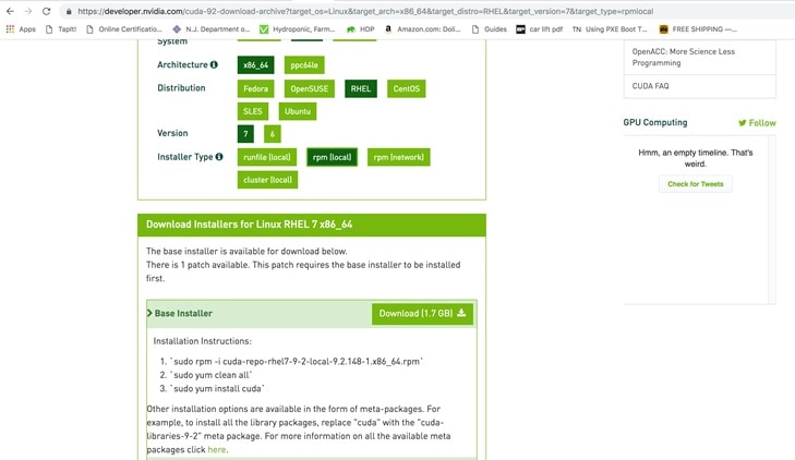
[root@rhel1 ~]# wget https://developer.nvidia.com/compute/cuda/9.2/Prod2/local_installers/cuda-repo-rhel7-9-2-local-9.2.148-1.x86_64
2. Copy .rpm file to all GPU nodes as follows:
[root@rhel1 ~]# ansible nodeswithgpu -m copy -a "src=/root/cuda-repo-rhel7-9-2-local-9.2.148-1.x86_64.rpm dest=/root/."
3. Install CUDA in all GPU nodes by running the following set of commands:
[root@rhel1 ~]# ansible nodeswithgpu -m shell -a "rpm -i cuda-repo-rhel7-9-2-local-9.2.148-1.x86_64.rpm"
[root@rhel1 ~]# ansible nodeswithgpu -m shell -a "yum clean all"
[root@rhel1 ~]# ansible nodeswithgpu -m shell -a "yum -y install cuda"
Download and Setup NVIDIA CUDA Deep Neural Network library (cuDNN)
Download cuDNN 9.2
1. Download cuDNN from https://developer.nvidia.com/cudnn for the same CUDA version.
2. Copy cuNN into all the GPU servers.
https://developer.nvidia.com/rdp/cudnn-archive
![]() This step may require to join the NVIDIA developer community.
This step may require to join the NVIDIA developer community.
3. Run the following Ansible commands in all GPU nodes to setup cuDNN:
[root@rhel1 ~]# ansible nodeswithgpu -m copy -a "src=/root/cudnn-9.2-linux-x64-v7.1.tgz dest=/root/."
[root@rhel1 ~]# ansible nodeswithgpu -m shell -a "tar -xzvf cudnn-9.2-linux-x64-v7.1.tgz"
[root@rhel1 ~]# ansible nodeswithgpu -m shell -a "cp /root/cuda/include/cudnn.h /usr/local/cuda-9.2/include"
[root@rhel1 ~]# ansible nodeswithgpu -m shell -a "cp /root/cuda/lib64/libcudnn* /usr/local/cuda-9.2/lib64"
[root@rhel1 ~]# ansible nodeswithgpu -m shell -a "chmod a+r /usr/local/cuda-9.2/include/cudnn.h /usr/local/cuda-9.2/lib64/libcudnn*"
Post Installation Steps
1. Add CUDA in PATH and LD_LIBRARY_PATH variable in all the GPU nodes.
2. The PATH and LD_LIBRARY_PATH variable need to include /usr/local/<cuda>/bin:
export PATH=/usr/local/cuda-9.2/bin${PATH:+:${PATH}}
export LD_LIBRARY_PATH=/usr/local/cuda-9.2/lib64${LD_LIBRARY_PATH:+:${LD_LIBRARY_PATH}}
3. Reboot the GPU nodes:
# ansible nodeswithgpu -a "/sbin/reboot"
![]() The SSH and Ansible connection will disconnect with this command.
The SSH and Ansible connection will disconnect with this command.
![]() For more information, go to: https://docs.nvidia.com/cuda/cuda-installation-guide-linux/index.html#post-installation-actions.
For more information, go to: https://docs.nvidia.com/cuda/cuda-installation-guide-linux/index.html#post-installation-actions.
Verify Drivers
To verify the drivers have been installed, run the following commands in all GPU nodes as shown below:
[root@rhel1 ~]# ansible nodeswithgpu -a "nvidia-smi"
Or on specific node
[root@rhel1 ~]# ansible rhel20.hdp3.cisco.com -a "nvidia-smi"
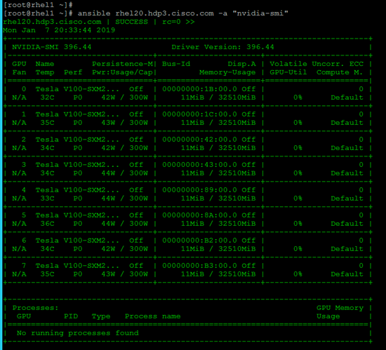
[root@rhel1 ~]# ansible nodeswithgpu -m shell -a "/usr/local/cuda-9.2/bin/nvcc --version"
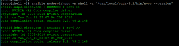
[root@rhel1 ~]# ansible nodeswithgpu -m shell -a "export NVIDIA_DRIVER_VERSION=396.44"
Install and Configure Docker
Prerequisites
Docker Version
Docker only supports systems with modern kernel as it is highly dependent on Linux OS kernel version and its capabilities.
YARN requires Docker should be setup and installed in all NodeManger hosts where Docker containers will run. It is important to consider these recommendations before installing Docker to be used by YARN.
Docker 1.12.5 is required at a minimum. However, it is recommended to use the latest version.
Storage Driver
It was observed through testing that device mapper using LVM is generally stable. However, high writes to the container root file system, device mapper exhibit panics. Overlay and Overlay2 perform significantly better than device mapper and recommended. In this reference architecture Overlay2 has been used.
Networking
YARN has support for running Docker containers on a user specified network, however, it does not manage the Docker networks. Administrators are expected to create the networks prior to running the containers. Node labels can be used to isolate particular networks. It is vital to read and understand the Docker networking documentation. Swarm based options are not recommended, however, overlay networks can be used if setup using an external store, such as etcd.
YARN will ask Docker for the networking details, such as IP address and hostname. As a result, all networking types are supported. Set the environment variable YARN_CONTAINER_RUNTIME_DOCKER_CONTAINER_NETWORK to specify the network to use.
Host networking is only recommended for testing. If the network where the NodeManagers are running has a sufficient number of IP addresses. The bridge networking with --fixed-cidr option works well. Each NodeManager is allocated a small portion of the larger IP space, and then allocates those IP addresses to containers.
To use an administrator defined network, add the network to docker.allowed.networks in container-executor.cfg and yarn.nodemanger.runtime.linux.docker.allowed-container-networks in yarn-site.xml .
![]() Setting up Docker Networking is beyond the scope of this CVD. This CVD focuses on standalone container for TensorFlow on YARN. Hadoop YARN is adding support for distributed TensorFlow applications and will be added as addendum when it is supported.
Setting up Docker Networking is beyond the scope of this CVD. This CVD focuses on standalone container for TensorFlow on YARN. Hadoop YARN is adding support for distributed TensorFlow applications and will be added as addendum when it is supported.
Image Management
Images can be preloaded on all NodeManager hosts or they can be implicitly pulled at runtime if they are available in a public Docker registry, such as Docker hub. If the image does not exist on the NodeManager and cannot be pulled, the container will fail.
![]() For AI framework specific images, it is recommend using Docker images from NG Cloud, which is described in subsequent sections of this document.
For AI framework specific images, it is recommend using Docker images from NG Cloud, which is described in subsequent sections of this document.
![]() It is also recommended to have a private Docker image repository. This CVD details the setup of a private registry for simplicity but doesn’t go into details on a registry setup with high availability and is provided only as an example.
It is also recommended to have a private Docker image repository. This CVD details the setup of a private registry for simplicity but doesn’t go into details on a registry setup with high availability and is provided only as an example.
Install Docker
To install Docker, follow these steps:
1. Uninstall any previous version of Docker completely by running the following command:
# yum remove docker docker-client docker-client-latest docker-common docker-latest docker-latest-logrotate docker-logrotate docker-selinux docker-engine-selinux docker-engine
2. Remove any existing Docker repository:
# rm /etc/yum.repos.d/docker*.repo
3. Docker has been released as part of Extra channel in Red Hat Enterprise Linux. When the extra channel has been enabled, docker packages can be installed. To register and subscribe a system to Red Hat customer portal, attached the required pool, and enable the extras channel, run the following commands:
# subscription-manager register --username <userid> --password <password>
# subscription-manager list --available
# subscription-manager attach --pool=<pool id>
# subscription-manager repos --disable='*'
# subscription-manager repos --enable="rhel-7-server-extras-rpms"
4. Install Docker by running the following command:
# ansible datanodes -m yum -a “name=docker state=present”
5. Start the Docker service:
# ansible datanodes -a “systemctl start docker”
# anaible datanodes -a “systemctl enable docker”
6. Verify Docker by running the following command:
# ansible datanodes -a “docker info”
Install nvidia-docker in GPU Nodes
To install nvidia-docker in GPU nodes, follow these steps:
1. In order for the Docker container to see GPU as a resource, you need to install nvidia-docker v1 plugin.
2. Add the package repositories:
# distribution=$(. /etc/os-release;echo $ID$VERSION_ID)
# ansible nodeswithgpu -m shell -a “curl -s -L https://nvidia.github.io/nvidia-docker/$distribution/nvidia-docker.repo | sudo tee /etc/yum.repos.d/nvidia-docker.repo”
3. Install nvidia-docker v1:
# ansible nodeswithgpu -m command -a “yum install -y nvidia-docker”
![]() nvidia-docker2 is not supported by HDP 3.0. Make sure you install nvidia-docker.
nvidia-docker2 is not supported by HDP 3.0. Make sure you install nvidia-docker.
4. Start the nvidia-docker service:
# ansible nodeswithgpu -m shell -a “systemctl start nvidia-docker”
# ansible nodeswithgpu -m shell -a “systemctl enable nvidia-docker”
5. Test nvidia-smi with the latest CUDA image. SSH to the node with GPU and run the following command:
# nvidia-docker run --rm nvidia/cuda:9.2-base nvidia-smi
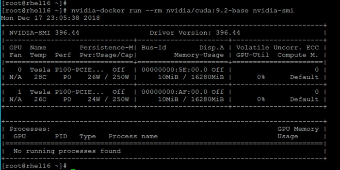
![]() For more information, go to: https://github.com/NVIDIA/nvidia-docker
For more information, go to: https://github.com/NVIDIA/nvidia-docker
6. Verify that the /var/lib/nvidia-docker/volumes/nvidia_driver/$NVIDIA_DRIVER_VERSION/ directory was created:
# ls /var/lib/nvidia-docker/volumes/nvidia_driver
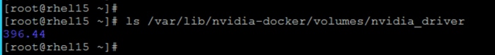
7. Run the following command to verify the nvidia-docker plugin:
[root@rhel15 lib64]# docker volume ls
[root@rhel15 lib64]# docker inspect volume nvidia_driver_396.44
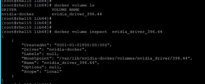
8. Use the following Docker command to verify that HDP can access the GPU:
# NVIDIA_DRIVER_VERSION=396.44
# docker run --device=/dev/nvidiactl --device=/dev/nvidia-uvm --device=/dev/nvidia0 -v /var/lib/nvidia-docker/volumes/nvidia_driver/$NVIDIA_DRIVER_VERSION/:/usr/local/nvidia/ -it nvidia/cuda:9.2-base /usr/local/nvidia/bin/nvidia-smi
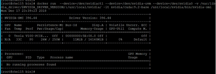
![]() On a multi-GPU server, the output of this command will show exactly one GPU. This is because we have run this sample docker container with only one device (/dev/nvidia0).
On a multi-GPU server, the output of this command will show exactly one GPU. This is because we have run this sample docker container with only one device (/dev/nvidia0).
Configure Docker
After Docker and nvidia-docker are installed, the following process is the minimum recommended configuration. To configure Docker, follow these steps:
![]() Configuring the storage driver is not included.
Configuring the storage driver is not included.
1. Edit /etc/docker/daemon.json and add the following options:
{
"live-restore" : true,
"debug" : true
}
![]() Live-restore keeps the container alive during daemon downtime.
Live-restore keeps the container alive during daemon downtime.
2. Restart Docker service:
ansible datanodes -m command -a “systemctl daemon-reload”
ansible datanodes -m command -a “systemctl restart docker”
Configure YARN to Running Docker Containers
YARN provides isolation through the use of cgroups. Docker also has cgroup management built in. If isolation through cgroups if desired, the only recommended solution is to use YARN’s cgroup management at this time. YARN will create the cgroup hierarchy and set the --cgroup-parent flag when launching the container.
The cgroupdriver must be set to cgroupfs in all datanodes where Docker is running. Ensure that Docker is running using the --exec-opt native.cgroupdriver=cgroupfs docker daemon option.
To configure YARN to run Docker containers, follow these steps:
vi /usr/lib/systemd/system/docker.service
1. Find and fix the cgroupdriver. If it is not there, it should be added.
--exec-opt native.cgroupdriver=cgroupfs \
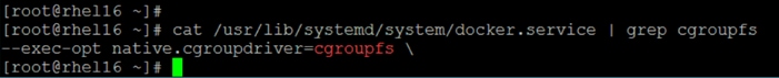
![]() The commands (above) should be configured on all the nodes where Docker is installed, on the datanodes.
The commands (above) should be configured on all the nodes where Docker is installed, on the datanodes.
2. The version of Docker may include oci-hooks that expect to use the systemd cgroup driver. Search for oci on your system and remove these files. For example:
[root@rhel1 ansible]# ansible datanodes -m shell -a " [ -f /usr/libexec/oci/hooks.d/oci-systemd-hook ] && echo 'File exist' || echo 'File does not exist'"
3. If it exists, run the following:
[root@rhel1 ansible]# ansible datanodes -m shell -a "rm -f /usr/libexec/oci/hooks.d/oci-systemd-hook”
ansible datanodes -m shell -a " [ -f /usr/libexec/oci/hooks.d/oci-register-machine] && echo 'File exist' || echo 'File does not exist'"
4. If it exists, remove the file:
ansible datanodes -m shell -a "rm -f /usr/libexec/oci/hooks.d/oci-register-machine”
Enable Cgroups
To set up the CGroup hierarchy, run the following command:
1. Create the following script in admin node:
[root@rhel1 ~]# vi hadoop-yarn.sh
mkdir -p /sys/fs/cgroup/cpu/hadoop-yarn
chown -R yarn /sys/fs/cgroup/cpu/hadoop-yarn
mkdir -p /sys/fs/cgroup/memory/hadoop-yarn
chown -R yarn /sys/fs/cgroup/memory/hadoop-yarn
mkdir -p /sys/fs/cgroup/blkio/hadoop-yarn
chown -R yarn /sys/fs/cgroup/blkio/hadoop-yarn
mkdir -p /sys/fs/cgroup/net_cls/hadoop-yarn
chown -R yarn /sys/fs/cgroup/net_cls/hadoop-yarn
mkdir -p /sys/fs/cgroup/devices/hadoop-yarn
chown -R yarn /sys/fs/cgroup/devices/hadoop-yarn
[root@rhel1 ~]#
2. Copy the script in all datanodes and run the script as shown below:
# ansible datanodes -m copy -a "src=/root/hadoop-yarn.sh dest=/root/."
# ansible datanodes -m file -a "dest=/root/hadoop-yarn.sh mode=755"
# ansible datanodes -m shell -a "/root/hadoop-yarn.sh"
![]() It is important to note that CGroup hierarchy MUST be created on every reboot of NodeManager node(s), otherwise the YARN NodeManager service will not start. It is recommend to be auto run on every system reboot and nodemanager reboot.
It is important to note that CGroup hierarchy MUST be created on every reboot of NodeManager node(s), otherwise the YARN NodeManager service will not start. It is recommend to be auto run on every system reboot and nodemanager reboot.
3. To enable cgroups on an Ambari cluster, select YARN > CONFIGS on the Ambari dashboard, then click CPU Isolation under CPU. Click Save.
4. Enable Docker Runtime by selecting YARN > CONFIGS > SETTINGS on the Ambari dashboard as shown below.
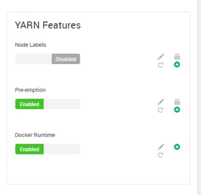
5. Set the following properties for Advanced yarn-site in Ambari.
Table 12 Advanced yarn-site Properties
| Properties |
Value |
| yarn.nodemanager.runtime.linux.allowed-runtimes |
default,docker |
| yarn.nodemanager.runtime.linux.docker.capabilities |
CHOWN,DAC_OVERRIDE,FSETID,FOWNER,MKNOD,NET_RAW,SETGID,SETUID, SETFCAP,SETPCAP,NET_BIND_SERVICE,SYS_CHROOT,KILL,AUDIT_WRITE |
| yarn.nodemanager.runtime.linux.docker.privilegedcontainers. allowed |
false |
| yarn.nodemanager.runtime.linux.docker.allowed-containernetworks |
host,bridge |
| yarn.nodemanager.runtime.linux.docker.default-containernetwork |
bridge |
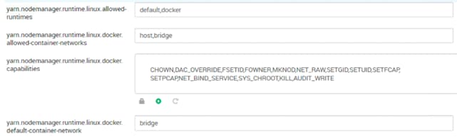
6. Configure the following isolation properties in YARN. In Ambari, click YARN > CONFIGS > ADVANCED. Properties can also be configured in the /etc/hadoop/conf/yarn-site.xml on the ResourceManager and NodeManager nodes. Configure and verify properties listed in Table 13 in Ambari so that changes get applied to all the respective nodes.
Table 13 YARN – Isolation Properties
| Property |
Value |
| yarn.nodemanager.container-executor.class |
org.apache.hadoop.yarn.server.nodemanager.LinuxContainerExecutor |
| yarn.nodemanager.linux-container-executor.cgroups.hierarchy |
/hadoop-yarn |
| yarn.nodemanager.linux-container-executor.cgroups.mount |
false |
| yarn.nodemanager.linux-container-executor.cgroups.mount-path |
/sys/fs/cgroup |
| yarn.nodemanager.linux-container-executor.cgroups.strict-resource-usage |
false |
| yarn.nodemanager.linux-container-executor.group |
hadoop |
| yarn.nodemanager.linux-container-executor.resources-handler.class |
org.apache.hadoop.yarn.server.nodemanager.util.CgroupsLCEResourcesHandler |
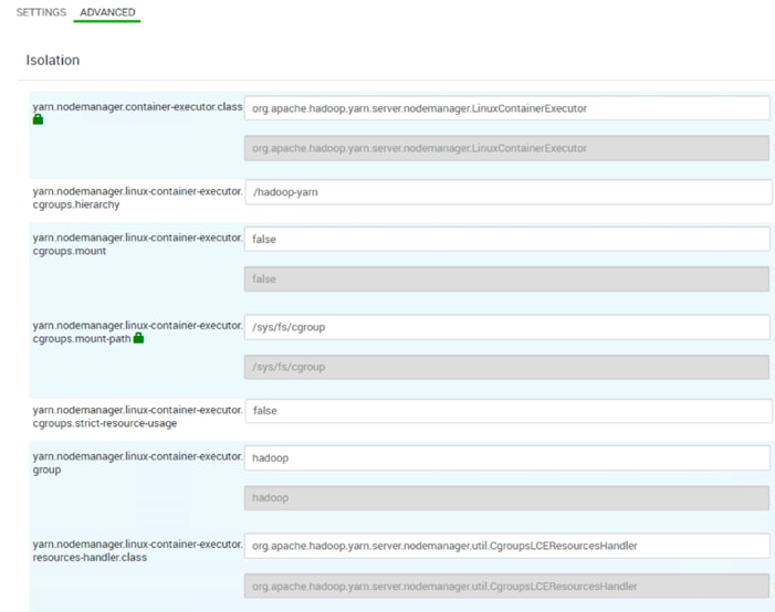
![]() To leverage YARN cgroup support, the NodeManager must be configured to use LinuxContainerExecutor. The Docker YARN integration also requires this container executor.
To leverage YARN cgroup support, the NodeManager must be configured to use LinuxContainerExecutor. The Docker YARN integration also requires this container executor.
7. Configure the following properties for Container Executor in YARN. Some properties are pre-set as per YARN recommendation.
Table 14 YARN – Container Executor Properties
| Properties |
Values |
| Docker Allowed Read-only Mounts |
/sys/fs/cgroup |
| Docker Binary |
/usr/bin/docker |
| Minimum user ID for submitting job |
50 |
| Yarn CGroup Hierarchy |
/hadoop-yarn |
8. The administrator must define the volume whitelist in container-executor.cfg by setting docker.allowed.ro-mounts and docker.allowed.rw-mounts to the list of parent directories that are allowed to be mounted.
The application submitter requests the required volumes at application submission time using the YARN_CONTAINER_RUNTIME_DOCKER_MOUNTS environment variable.
![]() Be careful when enabling this feature. Enabling access to directories such as, but not limited to, /, /etc, /run, or /home is not advisable and can result in containers negatively impacting the host or leaking sensitive information.
Be careful when enabling this feature. Enabling access to directories such as, but not limited to, /, /etc, /run, or /home is not advisable and can result in containers negatively impacting the host or leaking sensitive information.
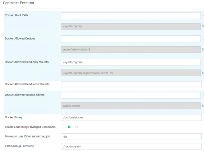
![]() /hadoop/yarn/local is a default Docker ro-mount. However, these are not mounted by default but are allowed to be mounted
/hadoop/yarn/local is a default Docker ro-mount. However, these are not mounted by default but are allowed to be mounted
CPU jobs are constrained with CPU scheduling and cgroups enabled, but by default these are flexible limits. If spare CPU cycles are available, containers are allowed to exceed the CPU limits set for them. With flexible limits, the amount of CPU resources available for containers to use can vary based on cluster usage; the amount of CPU available in the cluster at any given time.
You can use cgroups to set strict limits on CPU usage. When strict limits are enabled, each process receives only the amount of CPU resources it requests. With strict limits, a CPU process will receive the same amount of cluster resources every time it runs.
Strict limits are not enabled (set to false) by default for property yarn.nodemanager.linux-container-executor.cgroups.strict-resourceusage as shown above.
![]() Regardless of whether this property is true or false, at no point will the total container CPU usage exceed the limit set in yarn.nodemanager.resource.percentage-physical-cpu-limit.
Regardless of whether this property is true or false, at no point will the total container CPU usage exceed the limit set in yarn.nodemanager.resource.percentage-physical-cpu-limit.
9. Set the Percentage of CPU used by YARN. Set the percentage of CPU that can be allocated for YARN containers. In most cases, the default value of 100 percent should be used. If you have another process that needs to run on a node that also requires CPU resources, you can lower the percentage of CPU allocated to YARN to free up resources for the other process.
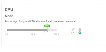 1
1
10. Click SAVE. Restart All Affected Services as shown below.
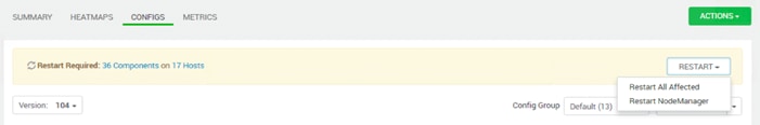
![]() These steps (above) configure the YARN Node Manager to run LinuxContainerExecutor in non-secure mode, just for demonstration purposes, so that all Docker containers scheduled by YARN will run as a ‘nobody’ user. Kerberized cluster with cgroups enabled is recommended for production.
These steps (above) configure the YARN Node Manager to run LinuxContainerExecutor in non-secure mode, just for demonstration purposes, so that all Docker containers scheduled by YARN will run as a ‘nobody’ user. Kerberized cluster with cgroups enabled is recommended for production.
Run Docker on YARN Using the YARN Service API
To deploy the web server using YARN service API, follow these steps:
1. Create the following Yarn file and save it to /tmp/httpdserver.json.
[root@rhel1 tmp]# cat httpdserver.json
{
"name":"httpd-service",
"version":"1.0.0",
"lifetime":"3600",
"configuration":{
"properties":{
"docker.network":"bridge"
}
},
"components":[
{
"name":"httpd",
"number_of_containers":1,
"artifact":{
"id":"centos/httpd-24-centos7:latest",
"type":"DOCKER"
},
"launch_command":"/usr/bin/run-httpd",
"resource":{
"cpus":1,
"memory":"1024"
},
"configuration":{
"files":[
{
"type":"TEMPLATE",
"dest_file":"/var/www/html/index.html",
"properties":{
"content":"<html><header><title>Title</title></header><body>Hello from ${COMPONENT_INSTANCE_NAME}!</body></html>"
}
}
]
}
}
]
}
[root@rhel1 tmp]#
2. Submit the HTTP application using the YARN CLI:
# yarn app -launch my-httpd httpdserver.json
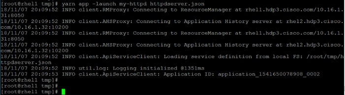
3. Get the IP address httpd container and the node where it is scheduled by running the following command:
[root@rhel1 tmp]# yarn app -status my-httpd
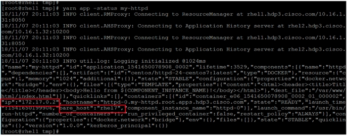
4. Verify the application through YARN ResourceManager web UI:
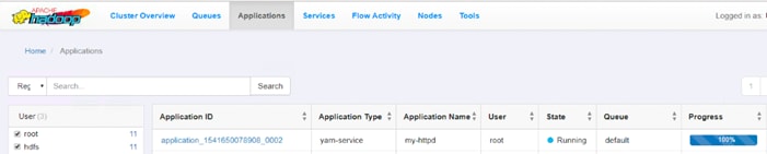
5. SSH to rhel7 and using curl, perform a GET request to the HTTP server on port 8080 using the IP address obtained in previous step:
# curl http://172.17.0.2:8080
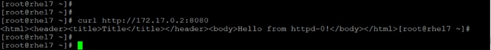
6. Run the following command to verify if Docker container is provisioned:
# docker ps -a
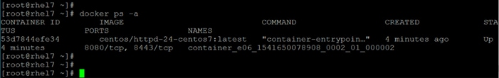
Run Docker Container with GPU on YARN
A GPU is a specialized processor that can be used to accelerate highly parallelized computationally-intensive workloads. Because of their computational power, GPUs have been found to be particularly well-suited to deep learning workloads. Ideally, CPUs and GPUs should be used in tandem for data engineering and data science workloads. A typical machine learning workflow involves data preparation, model training, model scoring, and model fitting. You can use existing general-purpose CPUs for each stage of the workflow, and optionally accelerate the math-intensive steps with the selective application of special-purpose GPUs. For example, GPUs allow you to accelerate model fitting using frameworks such as TensorFlow, Caffe, PyTorch, Keras, MXNet, and Microsoft Cognitive Toolkit (CNTK).
By enabling GPU support, data scientists can share GPU resources available on HDP nodes. Users can request a specific number of GPU instances, up to the total number available on a node, which are then allocated to the running session or job for the duration of the run.
Prerequisites
· Currently, only NVIDIA GPUs are supported by YARN
· NVIDIA drivers must be pre-installed in YARN node managers
When Docker is used as container runtime context, nvidia-docker 1.0 needs to be installed (the current supported version is YARN for nvidia-docker).
Enable GPU through Ambari
This section provides instructions about how to enable GPU support in HDP through Ambari.
If you have HDP cluster where datanodes with GPU installed and datanodes without GPU installed, you must create host groups. Enabling GPU in Ambari for non-GPU nodes will complain on restarting NodeManager service. Therefore, it is important to separate out the GPU nodes configuration by creating host group for GPU nodes.
Ambari initially assigns all hosts in your cluster to one default configuration group for each service you install. For example, after deploying a three-node cluster with default configuration settings, each host belongs to one configuration group that has default configuration settings for the HDFS service.
Create a New Host Configuration Group
To create host group, follow these steps:
1. Click a service name, for example, here we need to create host group for YARN. Click YARN > CONFIGS.
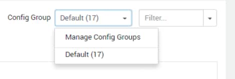
2. In Configs, click Manage Config Groups.
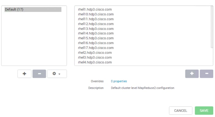
3. Click + icon on the left pane to create new configuration group. Create New Configuration Group window will pop-up as shown below. Provide a name to the configuration group. For example, GPU-Nodes
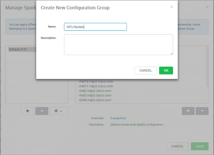
4. Click the newly created configuration group in the left pane and click + icon to add hosts to this group as shown below. Select hosts that has GPU and leave the non-GPU nodes in default configuration group.
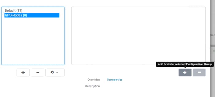
5. Click the check box on the hosts that have GPU installed as shown below. Click OK when done.
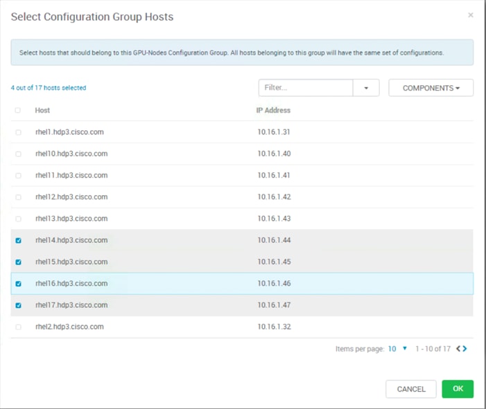
6. Click SAVE to save the configuration group as shown below.
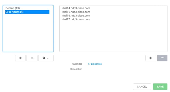
Enable GPU
To enable GPU, follow these steps:
1. Under default config group. In the GPU section, provide absolute path for nvidia-smi as shown below.
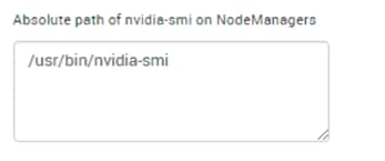
2. Select the GPU Nodes configuration group from Config group drop-down list created in the earlier steps as shown below. Select YARN > CONFIGS.
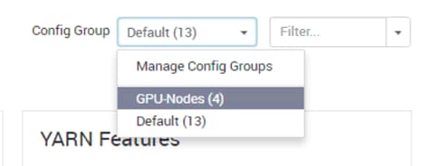
3. Click Enabled for GPU.
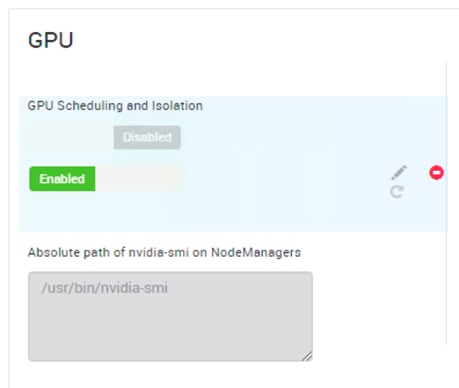
4. Verify Advanced yarn-site with the following:
| Properties |
Values |
| GPU docker plugin |
nvidia-docker-v1 (default) |
| GPU docker plugin endpoint for Nvidia Docker Version 1 |
http://localhost:3476/v1.0/docker/cli |
5. Click ADVANCED tab and verify the config for yarn.resource-types in Resource Types section as shown below.
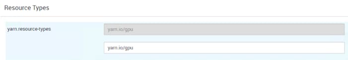
![]() For non-GPU nodes config group which is default in this case, make sure yarn.resource-types should also be yarn.io/gpu
For non-GPU nodes config group which is default in this case, make sure yarn.resource-types should also be yarn.io/gpu
6. Verify and/or apply the following settings for Container Executor in YARN config for GPU-nodes configuration group.
Table 15 YARN – Container Executor for GPU Properties
| Properties |
Values |
| CGroup Root Path |
/sys/fs/cgroup |
| Docker Allowed Devices |
regex:^/dev/nvidia.*$ |
| Docker Allowed Read-only Mounts |
/sys/fs/cgroup,regex:^nvidia_driver_.*$ |
| Docker Allowed Volume-drivers |
nvidia-docker |
| Docker Binary |
/usr/bin/nvidia-docker |
| Yarn CGroup Hierarchy |
/hadoop-yarn |
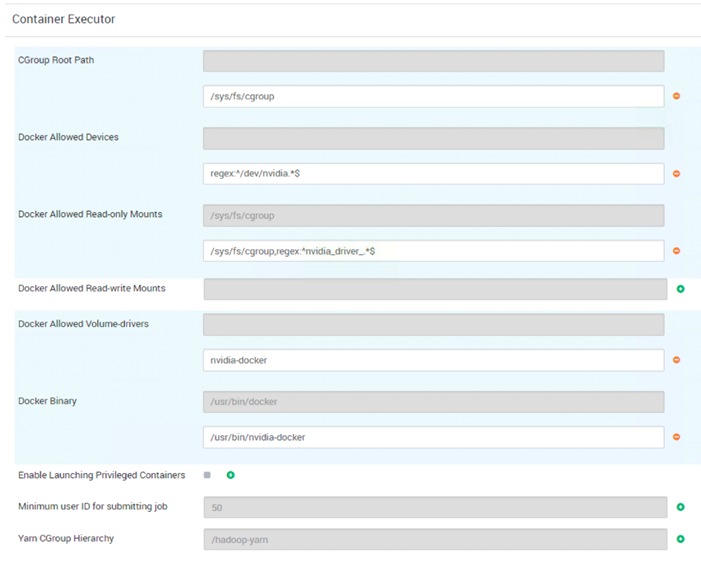
7. Click SAVE and RESTSRT for all affected services in Ambari.
Verify YARN Configurations
All of the configurations make changes in /etc/hadoop/conf/yarn-site.xml and /etc/hadoop/conf/container-executor.cfg file. To verify the YARN configurations, follow these steps:
1. For Non-GPU nodes, contents of /etc/hadoop/conf/container-executor.cfg file are in this reference design.
[root@rhel4 ~]# cat /etc/hadoop/conf/container-executor.cfg
#/*
# * Licensed to the Apache Software Foundation (ASF) under one
# * or more contributor license agreements. See the NOTICE file
# * distributed with this work for additional information
# * regarding copyright ownership. The ASF licenses this file
# * to you under the Apache License, Version 2.0 (the
# * "License"); you may not use this file except in compliance
# * with the License. You may obtain a copy of the License at
# *
# * http://www.apache.org/licenses/LICENSE-2.0
# *
# * Unless required by applicable law or agreed to in writing, software
# * distributed under the License is distributed on an "AS IS" BASIS,
# * WITHOUT WARRANTIES OR CONDITIONS OF ANY KIND, either express or implied.
# * See the License for the specific language governing permissions and
# * limitations under the License.
# */
yarn.nodemanager.local-dirs=/hadoop/yarn/local,/data/disk1/hadoop/yarn/local
yarn.nodemanager.log-dirs=/hadoop/yarn/log,/data/disk1/hadoop/yarn/log
yarn.nodemanager.linux-container-executor.group=hadoop
banned.users=hdfs,yarn,mapred,bin
min.user.id=50
[docker]
module.enabled=true
docker.binary=/usr/bin/docker
docker.allowed.capabilities=CHOWN,DAC_OVERRIDE,FSETID,FOWNER,MKNOD,NET_RAW,SETGID,SETUID,SETFCAP,SETPCAP,NET_BIND_SERVICE,SYS_CHROOT,KILL,AUDIT_WRITE
docker.allowed.devices=
docker.allowed.networks=host,bridge
docker.allowed.ro-mounts=/hadoop/yarn/local,/data/disk1/hadoop/yarn/local,/sys/fs/cgroup
docker.allowed.rw-mounts=/hadoop/yarn/local,/data/disk1/hadoop/yarn/local,/hadoop/yarn/log,/data/disk1/hadoop/yarn/log,
docker.privileged-containers.enabled=false
docker.trusted.registries=local,centos,hortonworks
docker.allowed.volume-drivers=
[gpu]
module.enabled=false
[cgroups]
root=
yarn-hierarchy=/hadoop-yarn
[root@rhel4 ~]#
2. For GPU nodes, contents of /etc/hadoop/conf/container-executor.cfg file are in this reference design.
[root@rhel16 ~]# cat /etc/hadoop/conf/container-executor.cfg
#/*
# * Licensed to the Apache Software Foundation (ASF) under one
# * or more contributor license agreements. See the NOTICE file
# * distributed with this work for additional information
# * regarding copyright ownership. The ASF licenses this file
# * to you under the Apache License, Version 2.0 (the
# * "License"); you may not use this file except in compliance
# * with the License. You may obtain a copy of the License at
# *
# * http://www.apache.org/licenses/LICENSE-2.0
# *
# * Unless required by applicable law or agreed to in writing, software
# * distributed under the License is distributed on an "AS IS" BASIS,
# * WITHOUT WARRANTIES OR CONDITIONS OF ANY KIND, either express or implied.
# * See the License for the specific language governing permissions and
# * limitations under the License.
# */
yarn.nodemanager.local-dirs=/hadoop/yarn/local,/data/disk1/hadoop/yarn/local
yarn.nodemanager.log-dirs=/hadoop/yarn/log,/data/disk1/hadoop/yarn/log
yarn.nodemanager.linux-container-executor.group=hadoop
banned.users=hdfs,yarn,mapred,bin
min.user.id=50
[docker]
module.enabled=true
docker.binary=/usr/bin/nvidia-docker
docker.allowed.capabilities=CHOWN,DAC_OVERRIDE,FSETID,FOWNER,MKNOD,NET_RAW,SETGID,SETUID,SETFCAP,SETPCAP,NET_BIND_SERVICE,SYS_CHROOT,KILL,AUDIT_WRITE
docker.allowed.devices=regex:^/dev/nvidia.*$
docker.allowed.networks=host,bridge
docker.allowed.ro-mounts=/hadoop/yarn/local,/data/disk1/hadoop/yarn/local,/sys/fs/cgroup,regex:^nvidia_driver_.*$
docker.allowed.rw-mounts=/hadoop/yarn/local,/data/disk1/hadoop/yarn/local,/hadoop/yarn/log,/data/disk1/hadoop/yarn/log,
docker.privileged-containers.enabled=false
docker.trusted.registries=local,centos,hortonworks
docker.allowed.volume-drivers=nvidia-docker
[gpu]
module.enabled=true
[cgroups]
root=/sys/fs/cgroup
yarn-hierarchy=/hadoop-yarn
[root@rhel16 ~]#
3. Launch the YARN Web UI and verify cluster overview as shown below.
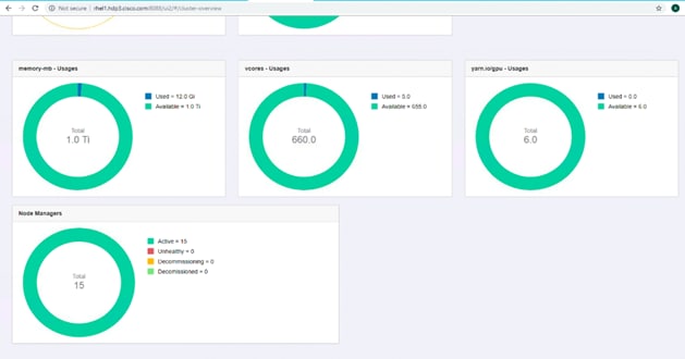
4. Click Nodes and select a node as shown below.
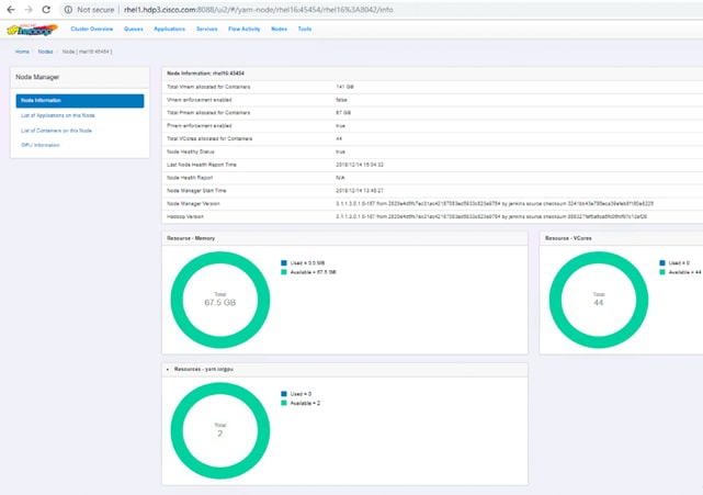
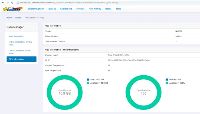
Setting Up Docker Registry
Private trusted registry is required to provision YARN container. This topic provides basic information about deploying and configuring a registry.
![]() This is a sample registry to showcase the use-case and not recommended for Production grade setup.
This is a sample registry to showcase the use-case and not recommended for Production grade setup.
Designate a Server for Docker and Start the Registry
To designate a server for Docker and start the registry, follow these steps:
1. Designate a server in the cluster for the Docker registry. Minimal resources are required, but sufficient disk space is needed to store the images and metadata. Docker must be installed and running.
2. Optional: By default, data will only be persisted within the container. If you would like to persist the data on the host, you can customize the bind mounts using the -v option.
3. Create /var/lib/registry folder:
# mkdir /var/lib/registry
4. Configure Docker to allow pulling from this insecure registry. Modify /etc/docker/daemon.json on all nodes in the cluster to include the following configuration options:
# cat /etc/docker/daemon.json
{
"live-restore" : true,
"debug" : true,
"insecure-registries" : ["linuxjh.hdp3.cisco.com:5000"]
}
5. Restart Docker on all nodes.
6. Provision the registry container by running the following command:
docker run -d -p 5000:5000 --restart=always --name registry -v /mnt/registry:/var/lib/registry registry:2
7. Verify the registry container is provisioned by running docker ps command:
[root@LinuxJB ~]# docker ps -a
CONTAINER ID IMAGE COMMAND CREATED STATUS PORTS NAMES
037d176d2576 registry:2 "/entrypoint.sh /etc…" 14 minutes ago Up 4 minutes 0.0.0.0:5000->5000/tcp registry
[root@LinuxJB ~]#
Test the Docker Registry
To test the Docker registry, follow these steps:
1. Pull the Docker image as shown in below:
[root@linuxjh dockerfile]# docker pull nvidia/cuda:9.2-base
9.2-base: Pulling from nvidia/cuda
18d680d61657: Already exists
0addb6fece63: Already exists
78e58219b215: Already exists
eb6959a66df2: Already exists
c7f8a5420911: Pull complete
f20e55ec643a: Pull complete
964bd7cf2ca3: Pull complete
Digest: sha256:de51e247fe0ecfde0fca7ef2d11285db79bd8afc0ef5adf7aade6aee4a9f5f72
Status: Downloaded newer image for nvidia/cuda:9.2-base
2. Tag the image:
[root@linuxjh dockerfile]# docker tag nvidia/cuda:9.2-base linuxjh.hdp3.cisco.com:5000/nvidia-cuda-cisco-demo
3. Push the image into private registry:
[root@LinuxJB ~]# docker push linuxjh. linuxjh.hdp3.cisco.com:5000/nvidia-cuda-cisco-demo
The push refers to repository [linuxjh.hdp3.cisco.com:5000/nvidia-cuda-cisco-demo]
ece4f9fdef59: Pushed
ad5345cbb119: Pushed
ef68f6734aa4: Pushed
latest: digest: sha256:87e9b6904b4286b8d41bba4461c0b736835fcc218f7ecbe5544b53fdd467189f size: 1778
[root@LinuxJB ~]#
Apache Hadoop YARN Distributed Shell
To run the YARN distributed shell with docker container having GPU as a resource, follow these steps:
1. Use the following command to run the distributed shell and GPU without a Docker container:
# export DJAR=”/usr/hdp/current/hadoop-yarn-client/hadoop-yarn-applications-distributedshell.jar”
# yarn jar $DJAR -jar $DJAR -shell_command "/usr/bin/nvidia-smi;sleep 120" -container_resources memory-mb=1024,vcores=1,yarn.io/gpu=1 -num_containers 1 -node_label_expression "gpu"
![]() Node labels can be created and assign to nodes containing GPU, so that YARN schedule the container where the GPU is installed. For configuring node labels, go to: https://docs.hortonworks.com/HDPDocuments/HDP3/HDP-3.0.1/data-operating-system/content/configuring_node_labels.html
Node labels can be created and assign to nodes containing GPU, so that YARN schedule the container where the GPU is installed. For configuring node labels, go to: https://docs.hortonworks.com/HDPDocuments/HDP3/HDP-3.0.1/data-operating-system/content/configuring_node_labels.html
2. Use the following command to run the distributed shell and GPU with a Docker container:
yarn jar $DJAR -jar $DJAR -shell_env YARN_CONTAINER_RUNTIME_TYPE=docker -shell_env YARN_CONTAINER_RUNTIME_DOCKER_IMAGE=linuxjh.hdp3.cisco.com:5000/nvidia-cuda-cisco-demo -shell_command "nvidia-smi;sleep 120" -container_resources memory-mb=1024,vcores=1,yarn.io/gpu=1 -num_containers 1 -node_label_expression "gpu"
3. On the YARN web UI, find the application and the node where it is provisioned as shown below and click prelaunch.out for _000002 container
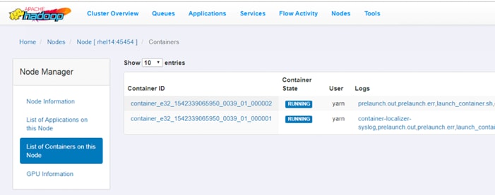
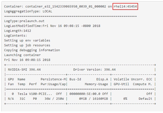
4. As shown in the figure above, the container is running in rhel14 node. ssh to rhel14 and run the following command:
[root@rhel14 ~]# docker ps
CONTAINER ID IMAGE COMMAND CREATED STATUS PORTS NAMES
37a3ba06cfe0 local/nvidia-cuda "bash /data/disk1/ha…" 58 seconds ago Up 58 seconds container_e32_1542339065950_0039_01_000002
[root@rhel14 ~]#
Run TensorFlow Container Using YARN Distributed Shell
In this example, Nvidia GPU Cloud (NGC) is used as the repository for AI frameworks Docker image. The TensorFlow Docker container image is pulled from NGC which is aligned to the CUDA installed on the server pulling the image.
To deploy TensorFlow container with YARN distributed shell, follow these steps:
1. Pull the tensorflow docker image as shown below:
# docker pull nvcr.io/nvidia/tensorflow:18.07-py3
2. Tag the image:
docker tag nvcr.io/nvidia/tensorflow:18.07-py3 linuxjh.hdp3.cisco.com:5000/nvcr-tf18.07-demo
3. Push the image to private registry:
1. [root@linuxjh dockerfile]# docker push linuxjh.hdp3.cisco.com:5000/nvcr-tf18.07-demo
2. The push refers to repository [linuxjh.hdp3.cisco.com:5000/nvcr-tf18.07-demo]
3. d36fbb9466ff: Preparing
4. 7101bec62098: Preparing
5. 7359bbd5e7f6: Preparing
6. ba881f735df8: Preparing
7. df07f5454848: Preparing
8. d36fbb9466ff: Pushed
9. 3211ba387e89: Mounted from nvcr-tf-demo
10. fc45365a529d: Mounted from nvcr-tf-demo
11. 0191fba0370f: Mounted from nvcr-tf-demo
12. f77fe3a5de0b: Mounted from nvcr-tf-demo
13.
14. [root@linuxjh dockerfile]# docker image ls
15. REPOSITORY TAG IMAGE ID CREATED SIZE
16. linuxjh.hdp3.cisco.com:5000/nvcr-tf18.07-demo latest a9950e6bf1b5 4 minutes ago 4.49GB
4. Run YARN distributed shell to provision tensorflow docker container in GPU nodes:
# export DJAR="/usr/hdp/current/hadoop-yarn-client/hadoop-yarn-applications-distributedshell.jar"
[root@rhel1 tmp]# yarn jar $DJAR -jar $DJAR -shell_env YARN_CONTAINER_RUNTIME_TYPE=docker -shell_env YARN_CONTAINER_RUNTIME_DOCKER_IMAGE=linuxjh.hdp3.cisco.com:5000/nvcr-tf18.07-demo -shell_command "python -c 'import tensorflow as tf; sess=tf.Session();print(sess.run(tf.constant(65)*tf.constant(445)))';sleep 300" -container_resources memory-mb=4096,vcores=2,yarn.io/gpu=6 -num_containers 1 -node_label_expression "c480ml"
![]() The node label was used in the command (above) so that YARN provisions the docker container in the node with GPU. In this reference example, rhel20.hdp3.cisco.com was assigned a node label named “c480ml”
The node label was used in the command (above) so that YARN provisions the docker container in the node with GPU. In this reference example, rhel20.hdp3.cisco.com was assigned a node label named “c480ml”
Below is the output of this command. Output has been truncated for simplicity:
[root@rhel1 tmp]# yarn jar $DJAR -jar $DJAR -shell_env YARN_CONTAINER_RUNTIME_TYPE=docker -shell_env YARN_CONTAINER_RUNTIME_DOCKER_IMAGE=linuxjh.hdp3.cisco.com:5000/nvcr-tf18.07-demo -shell_command "python -c 'import tensorflow as tf; sess=tf.Session();print(sess.run(tf.constant(65)*tf.constant(445)))';sleep 300" -container_resources memory-mb=4096,vcores=2,yarn.io/gpu=6 -num_containers 1 -node_label_expression "c480ml"
19/01/16 11:56:48 INFO distributedshell.Client: Initializing Client
19/01/16 11:56:48 INFO distributedshell.Client: Running Client
19/01/16 11:56:48 INFO client.RMProxy: Connecting to ResourceManager at rhel1.hdp3.cisco.com/10.16.1.31:8050
19/01/16 11:56:49 INFO client.AHSProxy: Connecting to Application History server at rhel2.hdp3.cisco.com/10.16.1.32:10200
19/01/16 11:56:49 INFO distributedshell.Client: Got Cluster metric info from ASM, numNodeManagers=16
19/01/16 11:56:49 INFO distributedshell.Client: Got Cluster node info from ASM
19/01/16 11:56:49 INFO distributedshell.Client: Got node report from ASM for, nodeId=rhel14:45454, nodeAddress=rhel14:8042, nodeRackName=/default-rack, nodeNumContainers=0
19/01/16 11:56:49 INFO distributedshell.Client: Got node report from ASM for, nodeId=rhel9:45454, nodeAddress=rhel9:8042, nodeRackName=/default-rack, nodeNumContainers=0
19/01/16 11:56:49 INFO distributedshell.Client: Got node report from ASM for, nodeId=rhel5:45454, nodeAddress=rhel5:8042, nodeRackName=/default-rack, nodeNumContainers=0
19/01/16 11:56:49 INFO distributedshell.Client: Got node report from ASM for, nodeId=rhel15:45454, nodeAddress=rhel15:8042, nodeRackName=/default-rack, nodeNumContainers=0
19/01/16 11:56:49 INFO distributedshell.Client: Got node report from ASM for, nodeId=rhel8:45454, nodeAddress=rhel8:8042, nodeRackName=/default-rack, nodeNumContainers=0
… Output truncated for readability
…
…
…
19/01/16 12:02:06 INFO distributedshell.Client: Got application report from ASM for, appId=11, clientToAMToken=null, appDiagnostics=, appMasterHost=rhel20.hdp3.cisco.com/10.16.1.50, appQueue=default, appMasterRpcPort=-1, appStartTime=1547668610305, yarnAppState=RUNNING, distributedFinalState=UNDEFINED, appTrackingUrl=http://rhel1.hdp3.cisco.com:8088/proxy/application_1547666438624_0011/, appUser=root
19/01/16 12:02:07 INFO distributedshell.Client: Got application report from ASM for, appId=11, clientToAMToken=null, appDiagnostics=, appMasterHost=rhel20.hdp3.cisco.com/10.16.1.50, appQueue=default, appMasterRpcPort=-1, appStartTime=1547668610305, yarnAppState=RUNNING, distributedFinalState=UNDEFINED, appTrackingUrl=http://rhel1.hdp3.cisco.com:8088/proxy/application_1547666438624_0011/, appUser=root
19/01/16 12:02:08 INFO distributedshell.Client: Got application report from ASM for, appId=11, clientToAMToken=null, appDiagnostics=, appMasterHost=rhel20.hdp3.cisco.com/10.16.1.50, appQueue=default, appMasterRpcPort=-1, appStartTime=1547668610305, yarnAppState=RUNNING, distributedFinalState=UNDEFINED, appTrackingUrl=http://rhel1.hdp3.cisco.com:8088/proxy/application_1547666438624_0011/, appUser=root
19/01/16 12:02:09 INFO distributedshell.Client: Got application report from ASM for, appId=11, clientToAMToken=null, appDiagnostics=, appMasterHost=rhel20.hdp3.cisco.com/10.16.1.50, appQueue=default, appMasterRpcPort=-1, appStartTime=1547668610305, yarnAppState=RUNNING, distributedFinalState=UNDEFINED, appTrackingUrl=http://rhel1.hdp3.cisco.com:8088/proxy/application_1547666438624_0011/, appUser=root
19/01/16 12:02:10 INFO distributedshell.Client: Got application report from ASM for, appId=11, clientToAMToken=null, appDiagnostics=, appMasterHost=rhel20.hdp3.cisco.com/10.16.1.50, appQueue=default, appMasterRpcPort=-1, appStartTime=1547668610305, yarnAppState=RUNNING, distributedFinalState=UNDEFINED, appTrackingUrl=http://rhel1.hdp3.cisco.com:8088/proxy/application_1547666438624_0011/, appUser=root
19/01/16 12:02:11 INFO distributedshell.Client: Got application report from ASM for, appId=11, clientToAMToken=null, appDiagnostics=, appMasterHost=rhel20.hdp3.cisco.com/10.16.1.50, appQueue=default, appMasterRpcPort=-1, appStartTime=1547668610305, yarnAppState=FINISHED, distributedFinalState=SUCCEEDED, appTrackingUrl=http://rhel1.hdp3.cisco.com:8088/proxy/application_1547666438624_0011/, appUser=root
19/01/16 12:02:11 INFO distributedshell.Client: Application has completed successfully. Breaking monitoring loop
19/01/16 12:02:11 INFO distributedshell.Client: Application completed successfully
5. Log into YARN Web UI and click the Applications tab as shown below.
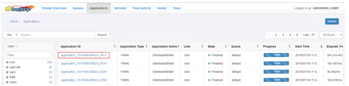
6. Click the application_1547666438624_0011 for details about the application, such as where it is provisioned by YARN. As shown below, this particular container is provisioned in rhel20.hdp3.cisco.com by YARN.
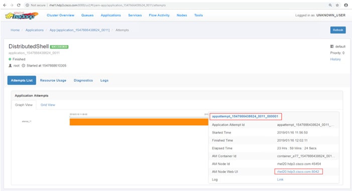
7. Click rhel20.hdp3.cisco.com. Detailed node information is displayed as shown below. Under Node Information tab, panel Resource yarn.io/gpu shows 6 GPUs is used and 2 GPUs are available. In the previous YARN distributed shell command mentioned in step 4, 6 GPUs were requested for the container.
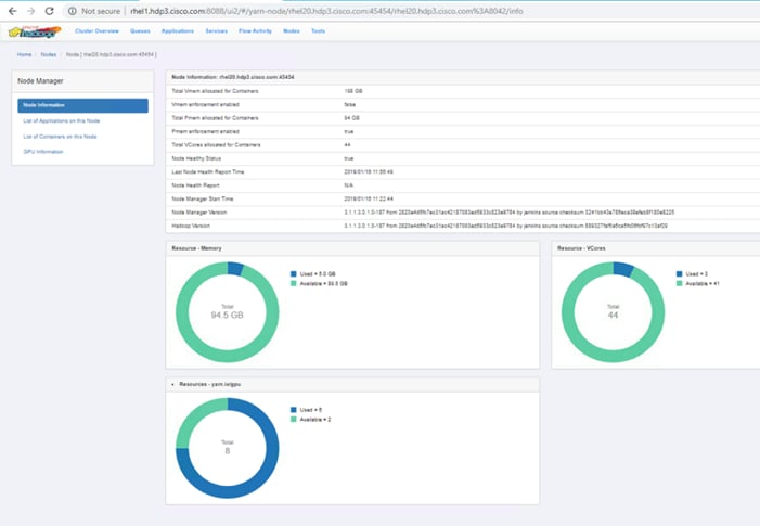
8. Click List of Containers on this Node. This displays the containers provisioned in this node, as shown below.
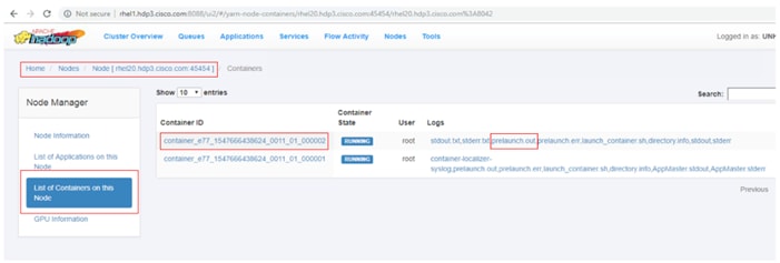
9. Click prelaunch.out to see the output of the container, as shown below
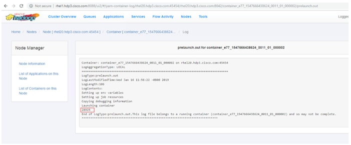
This section provides the BOM for the 24 Nodes Hadoop Base Rack and 8 Nodes Hadoop Expansion Rack. See Table 16 for the BOM for the Hadoop Base rack, Table 17 for BOM for Hadoop Expansion Rack, Table 18 for BOM for Hadoop GPU Rack, Table 19 for Red Hat Enterprise Linux License, and Table 20 lists Cloudera SKUs available from Cisco.
![]() If UCS-SP-CPA4-P2 is added to the BOM all the required components for 16 servers only are automatically added. If not customers can pick each of the individual components that are specified after this and build the BOM manually.
If UCS-SP-CPA4-P2 is added to the BOM all the required components for 16 servers only are automatically added. If not customers can pick each of the individual components that are specified after this and build the BOM manually.
Table 16 Bill of Materials for Cisco UCS C240 M5 SX Hadoop Nodes Base Rack
| Part Number |
Description |
Qty |
| UCS-SP-C240M5-A2 |
SP C240 M5SX w/2x6132,6x32GB mem,VIC1387 |
24 |
| CON-OSP-C240M5A2 |
SNTC 24X7X4OS UCS C240 M5 A2 |
24 |
| UCS-CPU-6132 |
2.6 GHz 6132/140W 14C/19.25MB Cache/DDR4 2666MHz |
48 |
| UCS-MR-X32G2RS-H |
32GB DDR4-2666-MHz RDIMM/PC4-21300/dual rank/x4/1.2v |
144 |
| UCSC-PCI-1-C240M5 |
Riser 1 including 3 PCIe slots (x8, x16, x8); slot 3 required CPU2 |
24 |
| UCSC-MLOM-C40Q-03 |
Cisco VIC 1387 Dual Port 40Gb QSFP CNA MLOM |
24 |
| UCSC-PSU1-1600W |
Cisco UCS 1600W AC Power Supply for Rack Server |
48 |
| CAB-9K12A-NA |
Power Cord, 125VAC 13A NEMA 5-15 Plug, North America |
48 |
| UCSC-RAILB-M4 |
Ball Bearing Rail Kit for C220 & C240 M4 & M5 rack servers |
24 |
| CIMC-LATEST |
IMC SW (Recommended) latest release for C-Series Servers. |
24 |
| UCSC-HS-C240M5 |
Heat sink for UCS C240 M5 rack servers 150W CPUs & below |
48 |
| UCSC-BBLKD-S2 |
UCS C-Series M5 SFF drive blanking panel |
624 |
| UCSC-PCIF-240M5 |
C240 M5 PCIe Riser Blanking Panel |
24 |
| CBL-SC-MR12GM5P |
Super Cap cable for UCSC-RAID-M5HD |
24 |
| UCSC-SCAP-M5 |
Super Cap for UCSC-RAID-M5, UCSC-MRAID1GB-KIT |
24 |
| UCSC-RAID-M5HD |
Cisco 12G Modular RAID controller with 4GB cache |
24 |
| UCS-SP-FI6332-2X |
UCS SP Select 2 x 6332 FI |
1 |
| UCS-SP-FI6332 |
(Not sold standalone) UCS 6332 1RU FI/12 QSFP+ |
2 |
| CON-OSP-SPFI6332 |
ONSITE 24X7X4 (Not sold standalone) UCS 6332 1RU FI/No PSU/3 |
2 |
| UCS-PSU-6332-AC |
UCS 6332 Power Supply/100-240VAC |
4 |
| CAB-9K12A-NA |
Power Cord, 125VAC 13A NEMA 5-15 Plug, North America |
4 |
| QSFP-H40G-CU3M |
40GBASE-CR4 Passive Copper Cable, 3m |
16 |
| QSFP-40G-SR-BD |
QSFP40G BiDi Short-reach Transceiver |
8 |
| N10-MGT015 |
UCS Manager v3.2(1) |
2 |
| UCS-ACC-6332 |
UCS 6332 Chassis Accessory Kit |
2 |
| UCS-FAN-6332 |
UCS 6332 Fan Module |
8 |
| QSFP-H40G-CU3M= |
40GBASE-CR4 Passive Copper Cable, 3m |
48 |
| UCS-SP-H1P8TB-4X |
UCS SP 1.8 TB 12G SAS 10K RPM SFF HDD (4K) 4Pk |
96 |
| UCS-SP-H1P8TB |
1.8 TB 12G SAS 10K RPM SFF HDD (4K) |
384 |
| UCS-SP-HD-1P8T-2 |
1.8TB 12G SAS 10K RPM SFF HDD (4K) 2 Pack |
16 |
| UCS-SP-HD-1P8T |
SP 1.8TB 12G SAS 10K RPM SFF HDD (4K) |
32 |
Table 17 Bill of Materials for Hadoop Nodes Expansion Rack
| Description |
Qty |
|
| UCS-SP-C240M5-A2 |
SP C240 M5SX w/2x6132,6x32GB mem,VIC1387 |
8 |
| CON-OSP-C240M5A2 |
SNTC 24X7X4OS UCS C240 M5 A2 |
8 |
| UCS-CPU-6132 |
2.6 GHz 6132/140W 14C/19.25MB Cache/DDR4 2666MHz |
16 |
| UCS-MR-X32G2RS-H |
32GB DDR4-2666-MHz RDIMM/PC4-21300/dual rank/x4/1.2v |
48 |
| UCSC-PCI-1-C240M5 |
Riser 1 including 3 PCIe slots (x8, x16, x8); slot 3 required CPU2 |
8 |
| UCSC-MLOM-C40Q-03 |
Cisco VIC 1387 Dual Port 40Gb QSFP CNA MLOM |
8 |
| UCSC-PSU1-1600W |
Cisco UCS 1600W AC Power Supply for Rack Server |
16 |
| CAB-9K12A-NA |
Power Cord, 125VAC 13A NEMA 5-15 Plug, North America |
16 |
| UCSC-RAILB-M4 |
Ball Bearing Rail Kit for C220 & C240 M4 & M5 rack servers |
8 |
| CIMC-LATEST |
IMC SW (Recommended) latest release for C-Series Servers. |
8 |
| UCSC-HS-C240M5 |
Heat sink for UCS C240 M5 rack servers 150W CPUs and below |
16 |
| UCSC-BBLKD-S2 |
UCS C-Series M5 SFF drive blanking panel |
208 |
| UCSC-PCIF-240M5 |
C240 M5 PCIe Riser Blanking Panel |
8 |
| CBL-SC-MR12GM5P |
Super Cap cable for UCSC-RAID-M5HD |
8 |
| UCSC-SCAP-M5 |
Super Cap for UCSC-RAID-M5, UCSC-MRAID1GB-KIT |
8 |
| UCSC-RAID-M5HD |
Cisco 12G Modular RAID controller with 4GB cache |
8 |
| UCS-SP-H1P8TB-4X |
UCS SP 1.8 TB 12G SAS 10K RPM SFF HDD (4K) 4Pk |
48 |
| UCS-SP-H1P8TB |
1.8 TB 12G SAS 10K RPM SFF HDD (4K) |
192 |
| UCS-SP-HD-1P8T-2 |
1.8TB 12G SAS 10K RPM SFF HDD (4K) 2 Pack |
8 |
| UCS-SP-HD-1P8T |
SP 1.8TB 12G SAS 10K RPM SFF HDD (4K) |
16 |
Table 18 Bill of Materials for Cisco UCS C480 ML Nodes Rack
| Part Number |
Description |
Qty |
| UCSC-C480-M5ML8 |
Chassis w/8GPU, NoPSU, NoRAID/cable, NoHDDmod, NoCPUmod |
1 |
| CON-OSP-480M5ML8 |
SNTC-24X7X4OS Chassis w/8GPU, NoPSU, NoRAID/cable, NoHDDmod, |
1 |
| UCSC-C480-CM |
UCS C480 M5 CPU Module w/o CPU, mem |
1 |
| UCS-CPU-6142 |
2.6 GHz 6142/150W 16C/22MB Cache/DDR4 2666MHz |
2 |
| UCS-MR-X32G2RS-H |
32GB DDR4-2666-MHz RDIMM/PC4-21300/dual rank/x4/1.2v |
12 |
| UCS-M2-960GB |
960GB SATA M.2 |
2 |
| UCSC-PSU1-1600W |
Cisco UCS 1600W AC Power Supply for Rack Server |
4 |
| CIMC-LATEST |
IMC SW (Recommended) latest release for C-Series Servers. |
1 |
| UCS-SID-INFR-BD |
Big Data and Analytics Platform (Hadoop/IoT/ITOA/AI/ML) |
1 |
| UCS-SID-WKL-BD |
Big Data and Analytics (Hadoop/IoT/ITOA) |
1 |
| UCSC-RAIL-4U-M5 |
Rail Kit for UCS C480 M5 |
1 |
| UCS-DIMM-BLK |
UCS DIMM Blanks |
12 |
| UCS-MSTOR-M2 |
Mini Storage carrier for M.2 SATA/NVME (holds up to 2) |
1 |
| UCSC-SCAP-M5 |
Super Cap for UCSC-RAID-M5, UCSC-MRAID1GB-KIT |
1 |
| CBL-SC-MR12GM5P |
Super Cap cable for UCSC-RAID-M5HD |
1 |
| UCSC-C480-CM-FLR |
UCS C480 M5 CPU Module Filler |
1 |
| UCSC-HS-02-EX |
CPU Heat Sink for UCS C480 M5 Rack Server |
2 |
| UCSC-BZL-EX-M5ML |
Optional Bezel for UCS C480 M5ML rack server |
1 |
| UCSC-C480-8HDD |
UCS C480 M5 Drive Module for 8x HDD |
1 |
| UCS-HD18TB10K4KN |
1.8TB 12G SAS 10K RPM SFF HDD (4K) |
8 |
| UCSC-C480-8HDD |
UCS C480 M5 Drive Module for 8x HDD |
1 |
| UCS-HD18TB10K4KN |
1.8TB 12G SAS 10K RPM SFF HDD (4K) |
8 |
| UCSC-C480-8HDD |
UCS C480 M5 Drive Module for 8x HDD |
1 |
| UCS-HD18TB10K4KN |
1.8TB 12G SAS 10K RPM SFF HDD (4K) |
8 |
| UCSC-RAID-M5HD |
Cisco 12G Modular RAID controller with 4GB cache |
1 |
| CAB-250V-10A-CN |
AC Power Cord - 250V, 10A - PRC |
4 |
Table 19 Red Hat Enterprise Linux License
| Red Hat Enterprise Linux |
||
| RHEL-2S2V-3A |
Red Hat Enterprise Linux |
28 |
| CON-ISV1-EL2S2V3A |
3 year Support for Red Hat Enterprise Linux |
28 |
Table 20 Cisco SKUs with Cisco PID and Product Names
| Cisco SKU |
Cisco PID with Duration |
Product Name |
| UCS-BD-HDP-JSS= |
UCS-BD-HDP-JSS-6M |
HDP Data Platform Jumpstart Subscription - Up to 16 Nodes – 1 Business Day Response - 6 Months |
| UCS-BD-HDP-ENT-ND= |
UCS-BD-ENT-ND-1Y |
HDP Enterprise Subscription - 4 Nodes - 24x7 Sev 1 Response - 1 Year |
| UCS-BD-HDP-ENT-ND= |
UCS-BD-ENT-ND-2Y |
HDP Enterprise Subscription - 4 Nodes - 24x7 Sev 1 Response - 2 Year |
| UCS-BD-HDP-ENT-ND= |
UCS-BD-ENT-ND-3Y |
HDP Enterprise Subscription - 4 Nodes - 24x7 Sev 1 Response - 3 Year |
| UCS-BD-HDP-EPL-ND= |
UCS-BD-EPL-ND-1Y |
HDP Enterprise Plus Subscription - 4 Nodes - 24x7 Sev 1 Response - 1 Year |
| UCS-BD-HDP-EPL-ND= |
UCS-BD-EPL-ND-2Y |
HDP Enterprise Plus Subscription - 4 Nodes - 24x7 Sev 1 Response - 2 Year |
| UCS-BD-HDP-EPL-ND= |
UCS-BD-EPL-ND-3Y |
HDP Enterprise Plus Subscription - 4 Nodes - 24x7 Sev 1 Response - 3 Year |
| UCS-BD-HDP-J2E-ND= |
UCS-BD-J2E-ND-U-1Y |
HDP Jumpstart to Enterprise Subscription Upgrade - 4 Nodes - 24x7 Sev 1 Response - 1 Year |
| UCS-BD-HDP-J2E-ND= |
UCS-BD-J2E-ND-U-2Y |
HDP Jumpstart to Enterprise Subscription Upgrade - 4 Nodes - 24x7 Sev 1 Response - 2 Year |
| UCS-BD-HDP-J2E-ND= |
UCS-BD-J2E-ND-U-3Y |
HDP Jumpstart to Enterprise Subscription Upgrade - 4 Nodes - 24x7 Sev 1 Response - 3 Year |
| UCS-BD-HDP-J2P-ND= |
UCS-BD-J2P-ND-U-1Y |
HDP Jumpstart to Enterprise Plus Subscription Upgrade - 4 Nodes - 24x7 Sev 1 Response - 1 Year |
| UCS-BD-HDP-J2P-ND= |
UCS-BD-J2P-ND-U-2Y |
HDP Jumpstart to Enterprise Plus Subscription Upgrade - 4 Nodes - 24x7 Sev 1 Response - 2 Year |
| UCS-BD-HDP-J2P-ND= |
UCS-BD-J2P-ND-U-3Y |
HDP Jumpstart to Enterprise Plus Subscription Upgrade - 4 Nodes - 24x7 Sev 1 Response - 3 Year |
| UCS-BD-HDP-E2P-ND= |
UCS-BD-E2P-ND-U-1Y |
HDP Enterprise to Enterprise Plus Subscription Upgrade - 4 Nodes - 24x7 Sev 1 Response - 1 Year |
| UCS-BD-HDP-E2P-ND= |
UCS-BD-E2P-ND-U-2Y |
HDP Enterprise to Enterprise Plus Subscription Upgrade - 4 Nodes - 24x7 Sev 1 Response - 2 Year |
| UCS-BD-HDP-E2P-ND= |
UCS-BD-E2P-ND-U-3Y |
HDP Enterprise to Enterprise Plus Subscription Upgrade - 4 Nodes - 24x7 Sev 1 Response - 3 Year |
Muhammad Afzal, Engineering Architect, Computing Systems Product Group, Cisco Systems, Inc.
Muhammad Afzal is an Engineering Architect and Technical Marketing Engineer in Cisco UCS Product Management and Datacenter Solutions Engineering. He is currently responsible for designing, developing, and producing validated architectures for Big Data and analytics while working collaboratively with product partners. Previously, Afzal had been a lead architect for various cloud and data center solutions in Solution Development Unit at Cisco. Prior to this, Afzal has been a Solutions Architect in Cisco’s Advanced Services group, where he worked closely with Cisco's large enterprise and service provider customers delivering data center and cloud solutions. Afzal holds an MBA in Finance and a BS in Computer Engineering.
Acknowledgements
For their support and contribution to the design, validation, and creation of this Cisco Validated Design, we would like to acknowledge the following for their significant contribution and expertise that resulted in developing this document:
· Karthik Kulkarni, Architect, Computing Systems Product Group, Cisco Systems, Inc.
· Silesh Bijjahalli, Product Management, Computing Systems Product Group, Cisco Systems, Inc.
· Ali Bajwa, Hortonworks
· Dhananjay Mehta, Hortonworks
· Harsh Shah, Hortonworks
· Wangda Tan, Hortonworks
· Sicong Ji, NVIDIA
· Chetan Tekur, NVIDIA
 Feedback