Preparing AXSM Cards and Lines for Communication
Available Languages
Table Of Contents
Preparing AXSM Cards and Lines for Communication
Managing Firmware Version Levels for AXSM Cards
Locating Cards that Need the Firmware Version Set
Verifying Card Firmware Version Levels
Verifying the Hardware Configuration
Establishing Redundancy Between Two AXSM Cards
Selecting and Viewing Service Class Templates
Establishing Redundancy Between Two Lines with APS
Preparing AXSM Cards and Lines for Communication
This chapter describes how to prepare AXSM cards and lines for configuration as ATM trunks and lines. "Provisioning AXSM Communication Links," describes how to configure the AXSM lines as ATM trunks and lines.
Configuration Quickstart
The quickstart procedure in this section provides a summary of the tasks required to prepare AXSM cards and lines for configuration as ATM trunks and lines. This procedure is provided as an overview and as a quick reference for those who have already configured the MGX 8850 switch.
Step 1
Start a configuration session.
Note: To perform all the procedures in this quickstart procedure, you must log in as a user with GROUP1 privileges or higher.
Step 2
Related commands:
dspcdsInitialize AXSM cards by setting the firmware version level for each AXSM card.
See "Managing Firmware Version Levels for AXSM Cards," which appears later in this chapter.
Step 3
Verify the hardware configuration.
See "Verifying the Hardware Configuration," which appears later in this chapter.
Step 4
Define which AXSM cards are operating as redundant cards.
See "Establishing Redundancy Between Two AXSM Cards," which appears later in this chapter.
Step 5
Related commands:
dspcdThis step applies ATM communications parameters in a preconfigured Service Class Template (SCT) file to all communications between the card you are configuring and the other AXSM cards in the switch.
Cisco policing SCT ID is 2, and non-policing SCT ID is 3.
See "Selecting and Viewing Service Class Templates," which appears later in this chapter.
Step 6
Related commands:
dsplnsdspln -type <bay.line>Bring up and configure lines. This step establishes physical connectivity between two switches.
See "Setting Up Lines," which appears later in this chapter.
Step 7
Related commands:
dsplnsdspln -type <bay.line>Configure lines.
See "Configuring Lines," which appears later in this chapter.
Step 8
This optional step configures a redundant relationship between two AXSM lines.
See "Establishing Redundancy Between Two Lines with APS," which appears later in this chapter.
Managing Firmware Version Levels for AXSM Cards
The AXSM cards within the switch run two types of firmware: boot firmware and runtime firmware. The boot firmware provides the basic information the card needs to start up and is installed on the board at the factory. The runtime firmware controls the operation of the card after startup, and the runtime firmware file is stored on the PXM45 hard disk back card.
After the AXSM cards are installed in the switch, you must specify the correct runtime firmware version for each card before the switch can begin using the card. The following sections explain how to
•
Locate the cards that need to have the firmware version level set.
•
•
Locating Cards that Need the Firmware Version Set
When an AXSM card is installed and the firmware version needs to be set, the System Status LED on the front of the card blinks red and the dspcds command shows that the card status is Failed. Other events can display these symptoms, but if the AXSM card is new, the problem is probably that the firmware version number has not been set. To locate the cards that need to have the firmware version set, use the following procedure.
Step 1
Step 2
mgx8850a.7.PXM.a > dspcdsThe following example shows the display for this command. The card state for the card in slot 2 is listed as Failed/Active. This is how a card appears when the runtime firmware version has not been selected.
pop20one.7.PXM.a > dspcdspop20one System Rev: 02.00 Jan. 26, 2001 16:35:42 PSTBackplane Serial No: SAA03211181 Bp HW Rev: B0 GMT Offset: -8Node Alarm: NONECard Front/Back Card Alarm Redundant RedundancySlot Card State Type Status Slot Type--- ---------- -------- -------- ------- -----01 Active/Active AXSM_4OC12 NONE NA NO REDUNDANCY02 Active/Active AXSM_4OC12 NONE NA NO REDUNDANCY03 Empty --- --- --- ---04 Empty --- --- --- ---05 Empty --- --- --- ---06 Empty --- --- --- ---07 Active/Active PXM45 NONE 08 PRIMARY SLOT08 Standby/Active PXM45 NONE 07 SECONDARY SLOT09 Empty --- --- --- ---10 Empty --- --- --- ---11 Empty --- --- --- ---12 Empty --- --- --- ---13 Empty --- --- --- ---14 Empty --- --- --- ---Note the slot number, card type, and redundancy type for each card that needs to have the firmware version set. You will need this information to activate these cards as described in the next section, "Initializing AXSM Cards."

Note
Initializing AXSM Cards
Before an AXSM card can operate, it must be initialized in a switch slot. The initialization process defines the AXSM runtime software version that will run on the card and identifies the slot in which the card operates. To initialize an AXSM card, use the following procedure.
Step 1

Tips
Step 2
Step 3
mgx8850a.7.PXM.a > setrev <slot> <version>
Note
Replace slot with the card slot number and replace version with the software version number. For example:
mgx8850a.7.PXM.a > setrev 1 2.0(12)After you enter the setrev command, the System status LED blinks red until the firmware load is complete, and then it changes to non-blinking green.
Step 4
Verifying Card Firmware Version Levels
When you are having problems with your switch, or when you've taken delivery of a new switch and delayed installation for a period of time, it is wise to verify the firmware versions installed on the switch. If newer versions of this firmware are available, installing the updated firmware can prevent switch problems.
To verify the firmware versions in use on your switch, use the following procedure.
Step 1
Step 2
Step 3
Verifying the Hardware Configuration
Before you can configure your switch, you need to collect information about the cards and software installed on the switch. You need to enter this information during the various configuration tasks. Table 3-1 shows the information you need and serves as a worksheet where you can enter this information.
The following procedure describes how to display the configuration information you need to enter in this table. It also describes how to verify that the correct upper and lower back cards are installed for each front card.
Step 1
Step 2
mgx8850a.7.PXM.a > dspcdsThe switch displays a report similar to the following:
pop20one.7.PXM.a > dspcdspop20one System Rev: 02.00 Jan. 26, 2001 16:35:42 PSTBackplane Serial No: SAA03211181 Bp HW Rev: B0 GMT Offset: -8Node Alarm: NONECard Front/Back Card Alarm Redundant RedundancySlot Card State Type Status Slot Type--- ---------- -------- -------- ------- -----01 Active/Active AXSM_4OC12 NONE NA NO REDUNDANCY02 Active/Active AXSM_4OC12 NONE NA NO REDUNDANCY03 Empty --- --- --- ---04 Empty --- --- --- ---05 Empty --- --- --- ---06 Empty --- --- --- ---07 Active/Active PXM45 NONE 08 PRIMARY SLOT08 Standby/Active PXM45 NONE 07 SECONDARY SLOT09 Empty --- --- --- ---10 Empty --- --- --- ---11 Empty --- --- --- ---12 Empty --- --- --- ---13 Empty --- --- --- ---14 Empty --- --- --- ---Step 3
•
•
•
Step 4
a.
mgx8850a.7.PXM.a > dspcd slotThe dspcd command displays information that is unique to a particular card. For PXM45 cards, the switch displays a report similar to the following:
pop20one.7.PXM.a > dspcd 7pop20one System Rev: 02.00 Jan. 26, 2001 16:39:47 PSTMGX8850 Node Alarm: NONESlot Number 7 Redundant Slot: 8Front Card Upper Card Lower Card---------- ---------- ----------Inserted Card: PXM45 UI Stratum3 PXM HardDiskDriveReserved Card: PXM45 UI Stratum3 PXM HardDiskDriveState: Active Active ActiveSerial Number: SAK03260058 SAK0332009P SAK0325007QPrim SW Rev: 2.0(12) --- ---Sec SW Rev: 2.0(12) --- ---Cur SW Rev: 2.0(12) --- ---Boot FW Rev: 2.0(12) --- ---800-level Rev: 06 04 03Orderable Part#: 800-05306-01 800-05787-01 800-05052-02CLEI Code: hReset Reason: On Power upCard Alarm: NONEFailed Reason: NoneMiscellaneous Information:Type <CR> to continue, Q<CR> to stop:pop20one System Rev: 02.00 Jan. 26, 2001 16:39:47 PSTMGX8850 Node Alarm: NONECrossbar Slot Status: PresentAlarm Causes------------NO ALARMS
Note
For AXSM cards, the switch displays a report similar to the following:
pop20one.7.PXM.a > dspcd 1pop20one System Rev: 02.00 Jan. 26, 2001 16:40:56 PSTMGX8850 Node Alarm: NONESlot Number: 1 Redundant Slot:Front Card Upper Card Lower Card---------- ---------- ----------Inserted Card: AXSM_4OC12 SMFIR_2_OC12 SMFIR_2_OC12Reserved Card: AXSM_4OC12 SMFIR_2_OC12 SMFIR_2_OC12State: Active Active ActiveSerial Number: SAK0344001V SBK0406002K SAK032800Q6Prim SW Rev: 2.0(12) --- ---Sec SW Rev: 2.0(12) --- ---Cur SW Rev: 2.0(12) --- ---Boot FW Rev: 2.0(12) --- ---800-level Rev:Orderable Part#: 800-05774-05 800-05383-01 800-05383-01CLEI Code: 1234567890 BAI9ADTAAA 0Reset Reason: On Power upCard Alarm: NONEFailed Reason: NoneMiscellaneous Information:Type <CR> to continue, Q<CR> to stop:pop20one System Rev: 02.00 Jan. 26, 2001 16:40:56 PSTMGX8850 Node Alarm: NONECrossbar Slot Status: PresentAlarm Causes------------NO ALARMSb.
–
–
–
–
Tips
Step 5
If any of the cards are installed incorrectly, refer to the Cisco MGX 8850 Hardware Installation Guide for instructions on installing the cards correctly.
Note
Establishing Redundancy Between Two AXSM Cards
To establish redundancy between two AXSM cards, use the following procedure.
Step 1
Step 2
Step 3
Step 4
pop20one.7.PXM.a > addred <redPrimarySlotNum> <redSecondarySlotNum> <redType>Replace redPrimarySlotNum with the slot number of the AXSM card that will be the primary card, and replace redSecondarySlotNum with the slot number of the secondary AXSM card. Replace redType with the number 1, which selects 1:1 Y cable redundancy. Although the online help lists other redundancy types, 1:1 Y cable redundancy is the only type supported on AXSM cards in this release.
Note
Tips
ERR: Secondary cd is already reserved, then lines are already in use on the specified secondary card. Use the dnln command to bring down these lines before re-entering the addred command.
After you enter the addred command, the switch resets the standby card, so it will be unavailable for a couple of minutes. When the reset is complete, a dspcds command will show the primary and secondary cards in the active and standby states, respectively, as shown in the following example.
pop20one.7.PXM.a > dspcdspop20one System Rev: 02.00 Jan. 26, 2001 16:44:58 PSTBackplane Serial No: SAA03211181 Bp HW Rev: B0 GMT Offset: -8Node Alarm: NONECard Front/Back Card Alarm Redundant RedundancySlot Card State Type Status Slot Type--- ---------- -------- -------- ------- -----01 Standby/Active AXSM_4OC12 NONE 02 SECONDARY SLOT02 Active/Active AXSM_4OC12 NONE 01 PRIMARY SLOT03 Empty --- --- --- ---04 Empty --- --- --- ---05 Empty --- --- --- ---06 Empty --- --- --- ---07 Active/Active PXM45 NONE 08 PRIMARY SLOT08 Empty Resvd/Empty --- MAJOR 07 SECONDARY SLOT09 Empty --- --- --- ---10 Active/Active AXSM_4OC12 NONE NA NO REDUNDANCY11 Empty --- --- --- ---12 Empty --- --- --- ---13 Empty --- --- --- ---14 Empty --- --- --- ---For information on managing redundant cards, refer to "Managing Redundant Cards," in Chapter 6, "Switch Operating Procedures."
Selecting and Viewing Service Class Templates
A Service Class Template (SCT) is a collection of ATM configuration parameter settings that are stored in a single file and can be applied to multiple lines or ports. Instead of retyping configuration data for identical lines or trunks, you can specify an SCT to apply those settings to additional lines and trunks. SCT files include the following types of configuration data:
•
•
•
•
•
There are two types of SCTs: card SCTs and port SCTs. Card SCTs define parameters that apply to all communications traffic between an AXSM card and the other AXSM cards in the switch. Port SCTs define parameters that apply to communications traffic on a single line or port. You can apply the same SCT to multiple cards or ports. To enable ATM communications, you must assign a card SCT to every card and a port SCT to every port you use.
The SCT files are stored in the C:\SCT\AXSM directory. Card SCT files are named AXSM_SCT.CARD.n, where n is the SCT ID number. Similarly, port SCT files are named AXSM_SCT.PORT.n. Cisco provides default SCT files you can use. The SCT ID 2 file provides parameter settings for policed connections, and SCT ID 3 serves non-policed connections. To create additional SCT files or change the configuration of existing SCT files, you need to use Cisco WAN Manager (CWM). You cannot create or modify SCT files using the CLI.
Note
The following sections describe how to select SCTs for cards and ports.
Selecting a Card SCT
A card SCT defines ATM parameters that apply to communications between the card you are configuring and the other AXSM cards in the switch. You can use the same SCT for multiple cards. To select an SCT for a card, use the following procedure.
Step 1
Step 2
pop20two.1.AXSM.a > cnfcdsct <sctID>Replace sctID with the number of the SCT that you want to assign to the card. The Cisco policing SCT ID is 2, and the non-policing SCT ID is 3. Valid SCT numbers are from 0 to 255; however, a valid SCT file must exist for the number you enter.
Step 3
pop20two.1.AXSM.a > dspcdThe display card report displays a row labeled "Card SCT Id," which identifies the SCT assigned to the card.
Selecting a Port SCT
A port SCT defines ATM parameters that apply to communications through a single port. You can use the same port SCT for multiple ports. To select an SCT for a port, use the addport command as described in "Adding ATM Ports" in "Provisioning AXSM Communication Links."
Setting Up Lines
The first step in configuring AXSM lines is to define the physical lines that are connected to the switch. The following sections describe how to do the following:
•
•
•
Bringing Up Lines
Installing an AXSM card can add 1 to 16 lines to your switch. You must bring up a line before you can configure the line or provision services on the line.
Before a line is brought up, or after it is brought down, the switch does not monitor the line. The AXSM port status light for the line is unlit, and all line alarms are cleared.
When you bring up a line, the switch starts monitoring the line. The AXSM port status light is green when physical layer communications are established with a remote switch. If physical layer communications problems are detected, the port status light turns red, and alarms are reported.
Note
Tips
To bring up a line on the switch, use the following procedure.
Step 1
Step 2
mgx8850a.7.PXM.a > cc <slotnumber>Replace slotnumber with the number of the slot in which the AXSM card is installed. Valid slot numbers are from 1 to 6 and 9 to 14. Verify your card selection by viewing the switch prompt, which should list the slot number and the AXSM card type.
Step 3
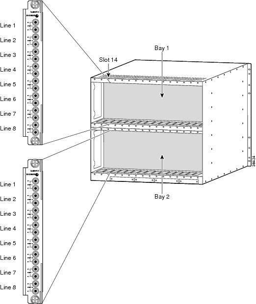
mgx8850a.10.AXSM.a > upln <bay.line>Replace bay with 1 if the line is connected to a back card in the upper bay, or replace it with 2 if the line is connected to a back card in the lower bay. Replace line with the number that corresponds to the back card port to which the line is connected. Table 3-3 lists the valid bay numbers and line numbers for each AXSM card. Figure 3-1 illustrates the bay and line numbers used on the MGX 8850 switch.
Table 3-3 AXSM Card Types
AXSM-16-155
1-8
1, 2
AXSM-4-622
1-4
1, 2
AXSM-1-2488
1
1
AXSM-16-T3E3
1-8
1, 2
Step 4
mgx8850a.10.AXSM.a > dsplnsThe line state column shows whether each line is up or down as shown in the following example:
pop20one.10.AXSM.a > dsplnsMedium MediumSonet Line Line Line Frame Line Line Alarm APSLine State Type Lpbk Scramble Coding Type State Enabled----- ----- ------------ ------ -------- ------ ------- ----- --------1.1 Up sonetSts12c NoLoop Enable Other ShortSMF Clear Disable1.2 Up sonetSts12c NoLoop Enable Other ShortSMF Clear Disable2.1 Up sonetSts12c NoLoop Enable Other ShortSMF Clear Disable2.2 Up sonetSts12c NoLoop Enable Other ShortSMF Clear DisableThe line state, which is either Up or Down, represents the administrative intent for the line. For example, a line is reported as Down until an administrator brings up the line. Once the administrator brings up the line, the line state remains Up until the administrator brings the line down (dnln command).
The alarm state indicates whether the line is communicating with a remote switch. When the alarm state is reported as Clear, the physical devices at each end of the line have established physical layer communications. ATM connectivity is established later when interfaces or ports are configured on the line.
Figure 3-1 Bay and Line Numbers
Configuring Lines
All line types are brought up with a default configuration. When configuring trunks between two MGX 8850 switches, you may be able to accept the defaults for each switch and minimize configuration time. When configuring a line to another type of device, ensure that both devices are using the same configuration parameters on the shared line.
At the physical communications level, you can configure the following:
•
•
•
•
•
•
The following procedure describes how to configure SONET, DS3, and E3 lines.
Step 1
Step 2
mgx8850a.10.AXSM.a > dsplnsRemember that you cannot configure a line until you have brought it up as described in the previous section, "Bringing Up Lines."
Step 3
mgx8850a.10.AXSM.a > cnfln -sonet <bay.line> -slt <LineType> -sfs <FrameScramble> -clk
<clockSource>
Table 3-4 lists the parameter descriptions for configuring SONET, DS3 and E3 lines. Be sure to use only the parameters listed above for SONET lines.
Table 3-4 Parameters for cnfln Command
AIScBitsCheck
T3
The -cb option defines C-bit checking. Set AIScBitsCheck to 1 to enable C-bit checking. Set it to 2 to ignore the C-bit.
bay
T3
E3
SONETReplace bay with 1 if the line is connected to a back card in the upper bay, or replace it with 2 if the line is connected to a back card in the lower bay.
clockSource
T3
E3
SONETThe -clk option selects the source timing for transmitting messages over the line. Replace clockSource with 1 to use the clock signal received over this line from a remote node, or specify 2 to use the local timing defined for the local switch. For information on defining the clock source for the local switch, see "Managing Network Clock Sources" in Chapter 2, "Configuring General Switch Features."
FrameScramble
SONET
The -sfs option enables or disables SONET frame scrambling. This setting must match the setting on the remote end of the line. Replace the FrameScramble variable with 1 to disable frame scrambling or 2 to enable frame scrambling.
line
T3
E3
SONETReplace line with the number that corresponds to the back card port to which the line is connected. Table 3-3 lists the valid line numbers for each AXSM card.
LineLength
T3
E3The -len option specifies the length of a T3 line from the local node to a remote node in meters. Enter a value between 0 and 64000 meters.
LineType
SONET
The -slt and -lt options specify the line type.
For SONET lines, replace the LineType variable with 1 for SONET or 2 for SDH.
For DS3 lines, replace the LineType variable with 1 for ds3cbitadm or 2 for ds3cbitplcp.
OOFCriteria
T3
Out Of Frame (OOF) alarm criteria. Replace OOFCriteria with 1 to select 3 out of 8 and 2 to select 3 out of 16.
RcvFEACValidation
T3
Replace RcvFEACValidation with 1 to select 4 out of 5 and 2 to select 8 out of 10.
Step 4
mgx8850a.10.AXSM.a > cnfln -ds3 <bay.line> -lt <LineType> -len <LineLength> -oof
<OOFCriteria> -cb <AIScBitsCheck> -rfeac <RcvFEACValidation> -clk <clockSource">
Table 3-4 lists the parameter descriptions for configuring SONET, DS3 and E3 lines. Be sure to use only the parameters listed above for DS3 lines.
Step 5
mgx8850a.10.AXSM.a > cnfln -ds3 <bay.line> -len <LineLength> -clk <clockSource">Table 3-4 lists the parameter descriptions for configuring SONET, DS3 and E3 lines. Be sure to use only the parameters listed above for E3 lines.
After you configure a line, you can verify the configuration by following the procedure in the next section.
Verifying Line Configuration
To display the configuration of a line, use the following procedure.
Step 1
Step 2
mgx8850a.10.AXSM.a > dsplnsStep 3
mgx8850a.10.AXSM.a > dspln -type <bay.line>The following table describes the command parameters.
type
The parameter specifies the type of line that is connected to the switch. Enter -sonet or -ds3. The -ds3 option works for DS3 and E3 lines.
bay
Replace bay with 1 if the line is connected to a back card in the upper bay, or replace it with 2 if the line is connected to a back card in the lower bay.
line
Replace line with the number that corresponds to the back card port to which the line is connected. Table 3-3 lists the valid line numbers for each AXSM card.
The line configuration appears as follows:
pop2one.10.AXSM.a > dspln -sonet 2.1Line Number : 2.1Admin Status : Up Alarm Status : ClearLoopback : NoLoop APS enabled : DisableFrame Scrambling : Enable Number of ports : 1Xmt Clock source : localTiming Number of partitions: 1Line Type : sonetSts12c Number of SPVC : 0Medium Type(SONET/SDH) : SONET Number of SVC : 4Medium Time Elapsed : 248198Medium Valid Intervals : 96Medium Line Type : ShortSMF
Establishing Redundancy Between Two Lines with APS
The switch supports two types of line redundancy:
•
•
The following sections describe how to add redundancy for these types of APS lines.
Adding Intracard APS Lines
To establish redundancy between two lines on the same card, use the following procedure.
Step 1
Step 2
Step 3
pop20two.1.AXSM.a > addapsln <workingIndex> <protectIndex> <archmode>Replace workingIndex with the with the location of the working line using the format "slot.bay.line." For example, to specify the line on card 2, bay 1, line 2, enter 2.1.2.
Replace protectIndex with the location of the protection line, using the same format used for the working line.
Note
Replace archmode with the option number that selects the APS architecture mode you want to use. Table 3-5 shows the option numbers and the architecture modes they select.
The following example shows assigns 1+1 APS redundancy to two lines on the same card:
pop20one.9.AXSM.a > addapsln 9.2.1 9.2.2 1Step 4
For information on managing redundant APS lines, refer to "Managing Redundant APS Lines," in Chapter 6, "Switch Operating Procedures."
Adding Intercard APS Lines
To establish redundancy between two lines on different cards, use the following procedure.
Step 1
Step 2
Step 3
Step 4
pop20one.7.PXM.a > addapsln <workingIndex> <protectIndex> <archmode>Replace workingIndex with the with the location of the working line using the format "slot.bay.line." For example, to specify the line on card 2, bay 1, line 2, enter 2.1.2.
Replace protectIndex with the location of the protection line, using the same format used for the working line.
Note
Replace archmode with an option number that defines the type of line redundancy you want to use. Table 3-5 shows the option numbers and the types of redundancy they select.
The following example shows assigns 1+1 APS redundancy to lines on different cards:
pop20one.1.AXSM.a > addapsln 1.1.2 2.1.2 1Step 5
For information on managing redundant APS lines, refer to "Managing Redundant APS Lines," in Chapter 6, "Switch Operating Procedures."
 Feedback