Configuring QoS
Prerequisites for QoS
Before configuring standard QoS, you must have a thorough understanding of these items:
-
The types of applications used and the traffic patterns on your network.
-
Traffic characteristics and needs of your network. For example, is the traffic on your network bursty? Do you need to reserve bandwidth for voice and video streams?
-
Bandwidth requirements and speed of the network.
-
Location of congestion points in the network.
General QoS Guidelines
These are the general QoS guidelines:
-
Control traffic (such as spanning-tree bridge protocol data units [BPDUs] and routing update packets) received by the switch are subject to all ingress QoS processing.
-
You are likely to lose data when you change queue settings; therefore, try to make changes when traffic is at a minimum.
Restrictions for QoS
The following are the restrictions for QoS:
-
The switch does not support classifying of traffic using class maps (class-map global configuration command).
-
Ingress queueing is not supported.
-
Interface restrictions:
-
Enable only cos trust at interface level.
-
Enable Weighted Round Robin (WRR) shaping at interface level.
-
Enable priority queueing at interface level.
-
Information About QoS
QoS Implementation
Typically, networks operate on a best-effort delivery basis, which means that all traffic has equal priority and an equal chance of being delivered in a timely manner. When congestion occurs, all traffic has an equal chance of being dropped.
When you configure the QoS feature, you can select specific network traffic, prioritize it according to its relative importance, and use congestion-management and congestion-avoidance techniques to provide preferential treatment. Implementing QoS in your network makes network performance more predictable and bandwidth utilization more effective.
The QoS implementation is based on the Differentiated Services (Diff-Serv) architecture, a standard from the Internet Engineering Task Force (IETF). This architecture specifies that each packet is classified upon entry into the network.
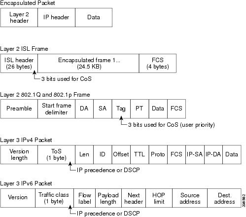
Layer 2 Frame Prioritization Bits
Layer 2 802.1Q frame headers have a 2-byte Tag Control Information field that carries the CoS value in the three most-significant bits, which are called the User Priority bits. On ports configured as Layer 2 802.1Q trunks, all traffic is in 802.1Q frames except for traffic in the native VLAN.
Other frame types cannot carry Layer 2 CoS values.
Layer 2 CoS values range from 0 for low priority to 7 for high priority.
QoS Basic Model
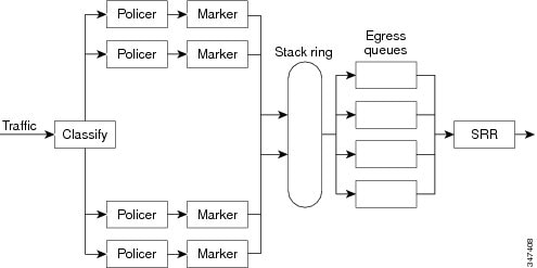
To implement QoS, the device must distinguish packets or flows from one another (classify), assign a label to indicate the given quality of service as the packets move through the device, make the packets comply with the configured resource usage limits (police and mark), and provide different treatment (queue and schedule) in all situations where resource contention exists. The device also needs to ensure that traffic sent from it meets a specific traffic profile (shape).
Mapping Tables Overview
During QoS processing, the switch represents the priority of all traffic (including non-IP traffic) with a QoS label based on the CoS value from the classification stage.
Before the traffic reaches the scheduling stage, QoS stores the packet in an egress queue according to the QoS label. The QoS label is based on the the CoS value in the packet and selects the queue through the CoS output queue threshold maps. In addition to an egress queue, the QOS label also identifies the WTD threshold value.
You configure these maps by using the mls qos wrr-queue { output } cos-map command in global configuration mode.
Queueing and Scheduling Overview
The switch has queues at specific points to help prevent congestion.
 Note |
The switch supports 4 egress queues by default and there is an option to enable a total of 8 egress queues. The 8 egress queue configuration is only supported on a standalone switch. |
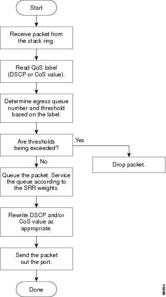
Queueing and Scheduling on Egress Queues
The following figure shows queueing and scheduling flowcharts for egress ports on the switch.
Note |
If the expedite queue is enabled, SRR services it until it is empty before servicing the other three queues. |
Egress Expedite Queue
Each port supports four egress queues, one of which (queue 1) can be the egress expedite queue. These queues are assigned to a queue-set. All traffic exiting the switch flows through one of these four queues and is subjected to a threshold based on the QoS label assigned to the packet.
Note |
If the expedite queue is enabled, SRR services it until it is empty before servicing the other three queues. |
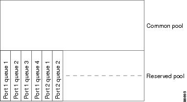
Egress Queue Buffer Allocation
The following figure shows the egress queue buffer.
Buffer and Memory Allocation
You guarantee the availability of buffers, set drop thresholds, and configure the maximum memory allocation for a queue-set by using the mls qos queue-set output qset-id threshold queue-id drop-threshold1 drop-threshold2 reserved-threshold maximum-threshold global configuration command. Each threshold value is a percentage of the queue’s allocated memory, which you specify by using the mls qos queue-set output qset-id buffers allocation1 ... allocation4 global configuration command. The sum of all the allocated buffers represents the reserved pool, and the remaining buffers are part of the common pool.
Through buffer allocation, you can ensure that high-priority traffic is buffered. For example, if the buffer space is 400, you can allocate 70 percent of it to queue 1 and 10 percent to queues 2 through 4. Queue 1 then has 280 buffers allocated to it, and queues 2 through 4 each have 40 buffers allocated to them.
You can guarantee that the allocated buffers are reserved for a specific queue in a queue-set. For example, if there are 100 buffers for a queue, you can reserve 50 percent (50 buffers). The switch returns the remaining 50 buffers to the common pool. You also can enable a queue in the full condition to obtain more buffers than are reserved for it by setting a maximum threshold. The switch can allocate the needed buffers from the common pool if the common pool is not empty.
Queues and WTD Thresholds
You can assign each packet that flows through the switch to a queue and to a threshold.
Specifically, you map CoS values to an egress queue and map CoS values to a threshold ID. You use the mls qos wrr-queue output cos-map queue queue-id {cos1...cos8 | threshold threshold-id cos1...cos8 } global configuration command. You can display the CoS output queue threshold map by using the show mls qos maps cos-output-q privileged EXEC command.
The queues use WTD to support distinct drop percentages for different traffic classes. Each queue has two drop thresholds. You assign the two WTD threshold percentages for threshold ID 1 and ID 2. The threshold percentages are not configurable.
Shaped Mode
You assign shaped weights to the port by using the wrr-queue bandwidth shape weight1 weight2 weight3 weight4 command in interface configuration mode.
The buffer allocation together with the WRR weight ratios control how much data can be buffered and sent before packets are dropped. The weight ratio is the ratio of the frequency in which the WRR scheduler sends packets from each queue.
All four queues participate in the WRR unless the expedite queue is enabled, in which case the first bandwidth weight is ignored and is not used in the ratio calculation. The expedite queue is a priority queue, and it is serviced until empty before the other queues are serviced. You enable the expedite queue by using the priority-queue out interface configuration command.
You can combine the commands described in this section to prioritize traffic by placing packets with particular CoSs into certain queues, by allocating a large queue size or by servicing the queue more frequently, and by adjusting queue thresholds so that packets with lower priorities are dropped.
Note |
The egress queue default settings are suitable for most situations. You should change them only when you have a thorough understanding of the egress queues and if these settings do not meet your QoS solution. |
Packet Modification
A packet is classified, and queued to provide QoS. The following packet modifications can occur during the process to provide QoS:
-
For IP and non-IP packets, classification involves assigning a QoS label to a packet based on the CoS of the received packet. However, the packet is not modified at this stage; only an indication of the assigned CoS value is carried along.
-
If you configure the port to trust the CoS of the incoming frame and it is an IP packet, the CoS value in the frame is not changed.
Standard QoS Default Configuration
QoS is disabled by default.
When QoS is disabled, there is no concept of trusted or untrusted ports because the packets are not modified. The CoS values in the packet are not changed.
Traffic is switched in pass-through mode. The packets are switched without any rewrites and classified as best effort without any policing.
When QoS is enabled using the mls qos global configuration command and all other QoS settings are at their defaults, traffic is classified as best effort (the CoS value is set to 0) without any policing. No policy maps are configured. The default port trust state on all ports is untrusted.
Default Egress Queue Configuration
The following tables describe the default egress queue configurations.
The following table shows the default egress queue configuration for each queue-set when QoS is enabled. All ports are mapped to queue-set 1. The port bandwidth limit is set to 100 percent and rate unlimited. Note that for the SRR shaped weights (absolute) feature, a shaped weight of zero indicates that the queue is operating in shared mode. Note that for the SRR shared weights feature, one quarter of the bandwidth is allocated to each queue.
|
Feature |
Queue 1 |
Queue 2 |
Queue 3 |
Queue 4 |
|---|---|---|---|---|
|
Buffer allocation |
25 percent |
25 percent |
25 percent |
25 percent |
|
WTD drop threshold 1 |
100 percent |
200 percent |
100 percent |
100 percent |
|
WTD drop threshold 2 |
100 percent |
200 percent |
100 percent |
100 percent |
|
Reserved threshold |
50 percent |
50 percent |
50 percent |
50 percent |
|
Maximum threshold |
400 percent |
400 percent |
400 percent |
400 percent |
|
SRR shaped weights (absolute) |
25 |
0 |
0 |
0 |
|
SRR shared weights |
25 |
25 |
25 |
25 |
The following table shows the default CoS output queue threshold map when QoS is enabled.
|
CoS Value |
Queue ID–Threshold ID |
|---|---|
|
0, 1 |
2–1 |
|
2, 3 |
3–1 |
|
4 |
4–1 |
|
5 |
1–1 |
|
6, 7 |
4–1 |
How to Configure QoS
The following sections provide information about how to configure QoS.
Enabling QoS Globally
By default, QoS is disabled on the switch.
The following procedure to enable QoS globally is required.
SUMMARY STEPS
- enable
- configure terminal
- mls qos
- end
- show mls qos
DETAILED STEPS
| Command or Action | Purpose | |||
|---|---|---|---|---|
| Step 1 |
enable Example: |
Enables privileged EXEC mode.
|
||
| Step 2 |
configure terminal Example: |
Enters global configuration mode. |
||
| Step 3 |
mls qos Example: |
Enables QoS globally. QoS operates with the default settings described in the related topic sections below.
|
||
| Step 4 |
end Example: |
Returns to privileged EXEC mode. |
||
| Step 5 |
show mls qos Example: |
Displays the multilayer switching (MLS) QoS information. |
Configuring Egress Queue Characteristics
Depending on the complexity of your network and your QoS solution, you might need to perform all of the tasks in the following modules. You need to make decisions about these characteristics:
-
Which packets are mapped by DSCP or CoS value to each queue and threshold ID?
-
What drop percentage thresholds apply to the queue-set (four egress queues per port), and how much reserved and maximum memory is needed for the traffic type?
-
How much of the fixed buffer space is allocated to the queue-set?
-
Does the bandwidth of the port need to be rate limited?
-
How often should the egress queues be serviced and which technique (shaped, shared, or both) should be used?
Configuration Guidelines
Follow these guidelines when the expedite queue is enabled or the egress queues are serviced based on their SRR weights:
-
If the egress expedite queue is enabled, it overrides the SRR shaped and shared weights for queue 1.
-
If the egress expedite queue is disabled and the SRR shaped and shared weights are configured, the shaped mode overrides the shared mode for queue 1, and SRR services this queue in shaped mode.
-
If the egress expedite queue is disabled and the SRR shaped weights are not configured, SRR services this queue in shared mode.
Allocating Buffer Space to and Setting WTD Thresholds for an Egress Queue-Set
You can guarantee the availability of buffers, set WTD thresholds, and configure the maximum allocation for a queue-set by using the mls qos queue-set output qset-id threshold queue-id drop-threshold1 drop-threshold2 reserved-threshold maximum-threshold global configuration command.
Each threshold value is a percentage of the queue’s allocated buffers, which you specify by using the mls qos queue-set output qset-id buffers allocation1 ... allocation4 global configuration command. The queues use WTD to support distinct drop percentages for different traffic classes.
Note |
The egress queue default settings are suitable for most situations. You should change them only when you have a thorough understanding of the egress queues and if these settings do not meet your QoS solution. |
Beginning in privileged EXEC mode, follow these steps to configure the memory allocation and to drop thresholds for a queue-set. This procedure is optional.
SUMMARY STEPS
- configure terminal
- interface interface-id
- queue-set qset-id
- end
- show mls qos interface [interface-id] buffers
- copy running-config startup-config
DETAILED STEPS
| Command or Action | Purpose | |
|---|---|---|
| Step 1 |
configure terminal Example: |
Enters the global configuration mode. |
| Step 2 |
interface interface-id Example: |
Specifies the port of the outbound traffic, and enter interface configuration mode. |
| Step 3 |
queue-set qset-id Example: |
Maps the port to a queue-set. For qset-id , enter the ID of the queue-set specified in Step 2. The range is 1 to 2. The default is 1. |
| Step 4 |
end Example: |
Returns to privileged EXEC mode. |
| Step 5 |
show mls qos interface [interface-id] buffers Example: |
Verifies your entries. |
| Step 6 |
copy running-config startup-config Example: |
(Optional) Saves your entries in the configuration file. To return to the default setting, use the no mls qos queue-set output qset-id buffers global configuration command. To return to the default WTD threshold percentages, use the no mls qos queue-set output qset-id threshold [ queue-id] global configuration command. |
Mapping CoS Values to an Egress Queue and to a Threshold ID
You can prioritize traffic by placing packets with particular class of service (CoS) into certain queues and adjusting the queue thresholds so that packets with lower priorities are dropped.
Note |
The egress queue default settings are suitable for most situations. You should change them only when you have a thorough understanding of egress queues and if these settings do not meet your QoS solution. |
Beginning in privileged EXEC mode, follow these steps to map CoS values to an egress queue and to a threshold ID. This procedure is optional.
SUMMARY STEPS
- enable
- configure terminal
- mls qos wrr-queue output cos-map queue queue-id threshold threshold-id cos1...cos8
- end
- show mls qos maps cos-output-q
DETAILED STEPS
| Command or Action | Purpose | |||
|---|---|---|---|---|
| Step 1 |
enable Example: |
Enables privileged EXEC mode.
|
||
| Step 2 |
configure terminal Example: |
Enters global configuration mode. |
||
| Step 3 |
mls qos wrr-queue output cos-map queue queue-id threshold threshold-id cos1...cos8 Example: |
By default, CoS values 0 and 1 are mapped to queue 2 and threshold 1. CoS values 2 and 3 are mapped to queue 3 and threshold 1. CoS values 4, 6, and 7 are mapped to queue 4 and threshold 1. CoS value 5 is mapped to queue 1 and threshold 1.
|
||
| Step 4 |
end Example: |
Returns to privileged EXEC mode. |
||
| Step 5 |
show mls qos maps cos-output-q Example: |
Displays multilayer switching (MLS) QoS mapping information for CoS output queues. The CoS output queue threshold map shows the CoS value in the top row and the corresponding queue ID and threshold ID in the second row; for example, queue 2 and threshold 2 (2-2). |
Configuring WRR Shaped Weights on Egress Queues
You can specify how much of the available bandwidth is allocated to each queue. The ratio of the weights is the ratio of the frequency in which the WRR scheduler sends packets from each queue.
You can configure the egress queues for shaped weights. Use shaping to smooth bursty traffic or to provide a smoother output over time.
Beginning in privileged EXEC mode, follow these steps to assign the shaped weights and to enable bandwidth shaping on the four egress queues mapped to a port. This procedure is optional.
SUMMARY STEPS
- enable
- configure terminal
- interface interface-id
- wrr-queue bandwidth shape weight1 weight2 weight3 weight4
- end
- show mls qos interface interface-id queueing
DETAILED STEPS
| Command or Action | Purpose | |
|---|---|---|
| Step 1 |
enable Example: |
Enables privileged EXEC mode.
|
| Step 2 |
configure terminal Example: |
Enters global configuration mode. |
| Step 3 |
interface interface-id Example: |
Specifies the port of the outbound traffic, and enters interface configuration mode. |
| Step 4 |
wrr-queue bandwidth shape weight1 weight2 weight3 weight4 Example: |
Assigns WRR weights to the egress queues. By default, weight1 is set to 25; weight2, weight3, and weight4 are set to 0. For weight1 weight2 weight3 weight4 , enter the weights to control the percentage of the port that is shaped. The inverse ratio (1/weight) controls the shaping bandwidth for this queue. Separate each value with a space. The range is 0 to 65535. To return to the default setting, use the no wrr-queue bandwidth shape interface configuration command. |
| Step 5 |
end Example: |
Returns to privileged EXEC mode. |
| Step 6 |
show mls qos interface interface-id queueing Example: |
Displays MLS QoS information at the interface level. |
Configuring the Egress Expedite Queue
You can ensure that certain packets have priority over all others by queuing them in the egress expedite queue. WRR services this queue until it is empty before servicing the other queues.
Beginning in privileged EXEC mode, follow these steps to enable the egress expedite queue. This procedure is optional.
SUMMARY STEPS
- enable
- configure terminal
- mls qos
- interface interface-id
- priority-queue out
- end
DETAILED STEPS
| Command or Action | Purpose | |||
|---|---|---|---|---|
| Step 1 |
enable Example: |
Enables privileged EXEC mode.
|
||
| Step 2 |
configure terminal Example: |
Enters global configuration mode. |
||
| Step 3 |
mls qos Example: |
Enables QoS on a switch. |
||
| Step 4 |
interface interface-id Example: |
Specifies the egress port, and enters interface configuration mode. |
||
| Step 5 |
priority-queue out Example: |
Enables the egress expedite queue, which is disabled by default. When you configure this command, the WRR weight and queue size ratios are affected because there is one fewer queue participating in WRR. This means that weight1 in the wrr-queue bandwidth shape command is ignored (not used in the ratio calculation).
|
||
| Step 6 |
end Example: |
Returns to privileged EXEC mode. |
Limiting the Bandwidth on an Egress Interface
You can limit the bandwidth on an egress port. For example, if a customer pays only for a small percentage of a high-speed link, you can limit the bandwidth to that amount.
Note |
The egress queue default settings are suitable for most situations. You should change them only when you have a thorough understanding of the egress queues and if these settings do not meet your QoS solution. |
Beginning in privileged EXEC mode, follow these steps to limit the bandwidth on an egress port. This procedure is optional.
SUMMARY STEPS
- enable
- configure terminal
- interface interface-id
- wrr-queue bandwidth limit weight1
- end
- show mls qos interface [interface-id ] queueing
DETAILED STEPS
| Command or Action | Purpose | |||
|---|---|---|---|---|
| Step 1 |
enable Example: |
Enables privileged EXEC mode.
|
||
| Step 2 |
configure terminal Example: |
Enters global configuration mode. |
||
| Step 3 |
interface interface-id Example: |
Specifies the port to be rate-limited, and enters interface configuration mode. |
||
| Step 4 |
wrr-queue bandwidth limit weight1 Example: |
Specifies the percentage of the port speed to which the port should be limited. The range is 10 to 90. By default, the port is not rate-limited and is set to 100 percent.
|
||
| Step 5 |
end Example: |
Returns to privileged EXEC mode. |
||
| Step 6 |
show mls qos interface [interface-id ] queueing Example: |
Displays MLS QoS queueing information at the interface level. |
Monitoring Standard QoS
|
Command |
Description |
|---|---|
|
show mls qos |
Displays global QoS configuration information. |
|
show mls qos interface [interface-id ] [ | queueing | statistics ] |
Displays QoS information at the port level, including the queueing strategy, and the ingress and egress statistics. |
|
show mls qos maps cos-output-q |
Displays QoS mapping information. |
|
show running-config | include rewrite |
Displays the transparency setting. |
Configuration Examples for QoS
Examples: Configuring Egress Queue Characteristics
This example shows how to configure bandwidth shaping on queue 1. The weight ratios for queues 2, 3, and 4 are set to 0 . The bandwidth weight for queue 1 is 1/8, which is 12.5 percent:
Device> enable
Device(config)# interface gigabitethernet 1/0/1
Device(config-if)# wrr-queue bandwidth shape 8 0 0 0
This example shows how to enable the egress expedite queue when the WRR weights are configured. The egress expedite queue overrides the configured WRR weights.
Device> enable
Device(config)# interface gigabitethernet 1/0/1
Device(config-if)# wrr-queue bandwidth shape 25 0 0 0
Device(config-if)# priority-queue out
Device(config-if)# end
This example shows how to limit the bandwidth on a port to 80 percent:
Device> enable
Device(config)# interface gigabitethernet 1/0/1
Device(config-if)# wrr-queue bandwidth limit 40
When you configure this command to 80 percent, the port is idle 20 percent of the time. The line rate drops to 80 percent of the connected speed, which is 800 Mb/s. These values are not exact because the hardware adjusts the line rate in increments of six.
Device# show mls qos interface gigabitethernet 1/0/1 queueing

GigabitEthernet1/0/1
Egress Priority Queue : enabled
Shaped queue weights (absolute) :  8 0 0 0
Shared queue weights  :  25 0 0 0
The port bandwidth limit : 40  (Operational Bandwidth:40.75)
Feature Information for QoS
This table provides release and related information for features explained in this module.
These features are available on all releases subsequent to the one they were introduced in, unless noted otherwise.
|
Release |
Feature |
Feature Information |
|---|---|---|
|
Cisco IOS Release 15.2(7)E3k |
QoS |
Implementing QoS in your network makes network performance more predictable and bandwidth utilization more effective. |
Use Cisco Feature Navigator to find information about platform and software image support. To access Cisco Feature Navigator, go to http://www.cisco.com/go/cfn.
 Feedback