The documentation set for this product strives to use bias-free language. For the purposes of this documentation set, bias-free is defined as language that does not imply discrimination based on age, disability, gender, racial identity, ethnic identity, sexual orientation, socioeconomic status, and intersectionality. Exceptions may be present in the documentation due to language that is hardcoded in the user interfaces of the product software, language used based on RFP documentation, or language that is used by a referenced third-party product. Learn more about how Cisco is using Inclusive Language.
The output of the show clock command on the device and PTP servo clock displayed in the output of the show platform software fed switch active ptp domain command are not synchronized. These are two different clocks used on the switch.
Inter-VLAN is not supported in PTP Transparent Clock Mode.
PTP is not supported on Cisco StackWise Virtual enabled devices.
The switch supports IEEE 802.1AS and IEEE 1588 Default profile and they are both mutually exclusive. Only one profile can
be enabled on the switch at a time.
The Cisco PTP implementation supports only the two-step clock and not the one-step clock. If the switch receives a one-step
message from the Grand Master Clock, the message will be dropped.
We do not recommend having non-PTP enabled devices in the PTP network since it decreases clock synchronization accuracy.
Signaling messages are not supported in Cisco IOS XE Gibraltar 16.12.1. These messages are dropped in the switch without
being processed.
Management messages with broadcast target id will be forwarded with a reduced hop count when the boundary clock mode is enabled.
Management messages will be forwarded without decreasing the boundary hop count when transparent clock mode is enabled.
Moving directly from one PTP mode to the other is not recommended. Clear the existing mode using no PTP mode and then configure a new mode.
IPv6 and VRF do not support PTP.
Transparent clock mode is not supported on native Layer 3 ports and EtherChannel interfaces. (boundary clock mode is supported
on native Layer 3 ports)
You cannot configure PTP on any port of a supervisor module.
Stateful Switchover (SSO) does not support PTP. The PTP protocol restarts after a switchover.
MACsec with Precision Time Protocol (PTP) is not supported.
Information About PTP
Precision Time Protocol (PTP) is defined in IEEE 1588 as Precision Clock Synchronization for Networked Measurements and Control
Systems, and was developed to synchronize the clocks in packet-based networks that include distributed device clocks of varying
precision and stability. PTP is designed specifically for industrial, networked measurement and control systems, and is optimal
for use in distributed systems because it requires minimal bandwidth and little processing overhead.
Why PTP?
Smart grid power automation applications such as peak-hour billing, virtual power generators, and outage monitoring and management,
require extremely precise time accuracy and stability. Timing precision improves network monitoring accuracy and troubleshooting
ability.
In addition to providing time accuracy and synchronization, the PTP message-based protocol can be implemented on packet-based
networks, such as Ethernet networks. The benefits of using PTP in an Ethernet network include:
Low cost and easy setup in existing Ethernet networks
Limited bandwidth is required for PTP data packets
Ethernet Switches and Delays
Precision Time Protocol (PTP) is defined in IEEE 1588 as Precision Clock Synchronization for Networked Measurements and Control
Systems, and was developed to synchronize the clocks in packet-based networks that include distributed device clocks of varying
precision and stability. PTP is designed specifically for industrial, networked measurement and control systems, and is optimal
for use in distributed systems because it requires minimal bandwidth and little processing overhead.
Why PTP?
In an Ethernet network, switches provide a full-duplex communication path between network devices. Switches send data packets
to packet destinations using address information contained in the packets. When the switch attempts to send multiple packets
simultaneously, some of the packets are buffered by the switch so that they are not lost before they are sent. When the buffer
is full, the switch delays sending packets. This delay can cause device clocks on the network to lose synchronization with
one another.
Additional delays can occur when packets entering a switch are stored in local memory while the switch searches the MAC address
table to verify packet CRC fields. This process causes variations in packet forwarding time latency, and these variations
can result in asymmetrical packet delay times.
Adding PTP to a network can compensate for these latency and delay problems by correctly adjusting device clocks so that they
stay synchronized with one another. PTP enables network switches to function as PTP devices, including boundary clocks (BCs)
and transparent clocks (TCs).
Message-based Synchronisation
To ensure clock synchronization, PTP requires an accurate measurement of the communication path delay between the time source
(master ) and the receiver (slave ). PTP sends messages between the master and slave device to determine the delay measurement.
Types of messages are described in detail in PTPv2 Message Types. Then, PTP measures the exact message transmit and receive times and uses these times to calculate the communication path
delay. PTP then adjusts current time information contained in network data for the calculated delay, resulting in more accurate
time information.
This delay measurement principle determines path delay between devices on the network, and the local clocks are adjusted for
this delay using a series of messages sent between masters and slaves. The one-way delay time is calculated by averaging the
path delay of the transmit and receive messages. This calculation assumes a symmetrical communication path; however, switched
networks do not necessarily have symmetrical communication paths, due to the buffering process.
PTP provides a method, using transparent clocks, to measure and account for the delay in a time-interval field in network
timing packets, making the switches temporarily transparent to the master and slave nodes on the network. An end-to-end transparent
clock forwards all messages on the network in the same way that a switch does.
Note
Cisco PTP supports multicast PTP messages only.
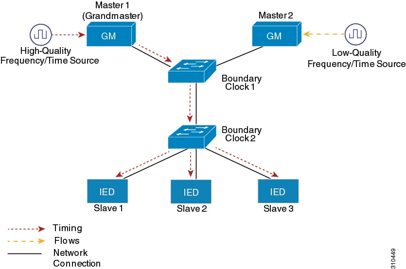
The following figure shows a typical 1588 PTP network that includes grandmaster clocks, switches in boundary clock mode, and
Intelligent Electronic Device (IEDs) such as a digital relays or protection devices. In this diagram, Master 1 is the grandmaster
clock. If Master 1 becomes unavailable, the boundary clock slaves switch to Master 2 for synchronization.
Figure 1. PTP Network
PTPv2 Message Types
PTP messages are categorized into the following two types:
Event Messages — Event messages are tagged with a timestamp when data packets are reaching or leaving a port and are used
to calculate the link delay based on the timestamps. Event messages are listed below:
Sync
Delay_Req
Pdelay_Req
Pdelay_Resp
Announce messages are used to establish the synchronization hierarchy.
General Messages — General messages are not tagged with timestamps and are used to establish a master-slave hierarchy. General
messages are listed below:
Announce
Follow_Up
Delay_Resp
Pdelay_Resp_Follow_Up
Sync, Delay_Req, Follow_Up, and Delay_Resp messages are used to synchronize ordinary and boundary clocks.
Pdelay_Req, Pdelay_Resp, and Pdelay_Resp_Follow_Up messages are used to measure the link delay in transparent clocks.
The (Best Master Clock Algorithm (BMCA) elects the grandmaster clock and assign the ports as master or slave. Following this, all the master ports start sourcing
the clock to the downstream slaves using the Sync and Follow_Up messages. The downstream slaves receive the clock and update
their clock after computing the delay of the link, time offset, frequency offset and drift error parameters.
The downstream slaves computes the link delay using one of the below mechanism.
This section describes the PTP event message sequences that occur during synchronization.
End-to-End Delay Mechanism
The ordinary and boundary clocks that are configured for the delay request-response mechanism use the following event messages
to generate and communicate timing information:
Sync
Delay_Req
Follow_Up
Delay_Resp
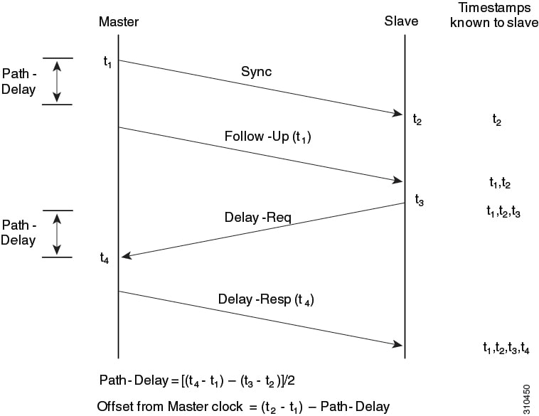
These messages are sent in the following sequence:
The master sends a Sync message to the slave and notes the time (t1) at which it was sent.
The slave receives the Sync message and notes the time of reception (t2).
The master conveys to the slave the timestamp t1 by embedding the timestamp t1 in a Follow_Up message.
The slave sends a Delay_Req message to the master and notes the time (t3) at which it was sent.
The master receives the Delay_Req message and notes the time of reception (t4).
The master conveys to the slave the timestamp t4 by embedding it in a Delay_Resp message.
After this sequence, the slave possesses all four timestamps. These timestamps can be used to compute the offset of the slave
clock relative to the master, and the mean propagation time of messages between the two clocks.
The offset calculation is based on the assumption that the time for the message to propagate from master to slave is the same
as the time required from slave to master. Assumption is not always valid on an Ethernet network due to asymmetrical packet
delay times.
Figure 2. End-to-End Delay Mechanism
Peer-to-Peer Delay Mechanism
When the network includes multiple levels of boundary clocks in the hierarchy, with non-PTP enabled devices between them,
synchronization accuracy decreases.
The round-trip time is assumed to be equal to mean_path_delay/2, however this is not always valid for Ethernet networks. To
improve accuracy, the resident time of each intermediary clock is added to the offset in the end-to-end transparent clock.
Resident time, however, does not take into consideration the link delay between peers, which is handled by peer-to-peer transparent
clocks.
Peer-to-peer transparent clocks measure the link delay between two clock ports implementing the peer delay mechanism. The
link delay is used to correct timing information in Sync and Follow_Up messages.
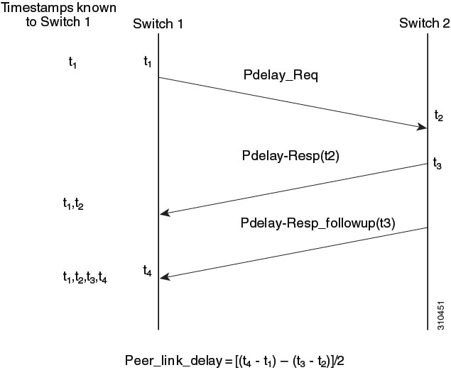
Peer-to-peer transparent clocks use the following event messages:
Pdelay_Req
Pdelay_Resp
Pdelay_Resp_Follow_Up
These messages are sent in the following sequence:
Port 1 generates timestamp t1 for a Pdelay_Req message.
Port 2 receives and generates timestamp t2 for this message.
Port 2 returns and generates timestamp t3 for a Pdelay_Resp message.
To minimize errors due to any frequency offset between the two ports, Port 2 returns the Pdelay_Resp message as quickly as
possible after the receipt of the Pdelay_Req message.
Port 2 returns timestamps t2 and t3 in the Pdelay_Resp and Pdelay_Resp_Follow_Up messages respectively.
Port 1 generates timestamp t4 after receiving the Pdelay_Resp message. Port 1 then uses the four timestamps (t1, t2, t3, and
t4) to calculate the mean link delay.
In an ideal PTP network, the master and slave clock operate at the same frequency. However, drift can occur on the network.
Drift is the frequency difference between the master and slave clock. You can compensate for drift by using the time stamp
information in the device hardware and follow-up messages (intercepted by the switch) to adjust the frequency of the local
clock to match the frequency of the master clock.
Best Master Clock Algorithm
The Best Master Clock Algorithm (BMCA) is the basis of PTP functionality. The BMCA specifies how each clock on the network
determines the best master clock in its subdomain of all the clocks it can see, including itself. The BMCA runs locally on
each port in the network continuously for every Announce interval and quickly adjusts for changes in network configuration.
BMCA based on IEEE 1588-2008 uses Announce messages for advertising clock properties.
The BMCA uses the following criteria to determine the best master clock in the subdomain:
Clock quality (for example, GPS is considered the highest quality)
Clock accuracy of the clock’s time base
Stability of the local oscillator
Closest clock to the grandmaster
BMCA based on IEEE 1588-2008 uses own data set with the received data set to determine the best clock based on the attributes
with the following properties, in the indicated order:
Priority1 - User-assigned priority to each clock. The range is from 0 to 255. The default value is 128.
Class - Class to which the a clock belongs to, each class has its own priority
Accuracy - Precision between clock and UTC, in nanoseconds
Variance - Variability of the clock
Priority2 - Final-defined priority. The range is from 0 to 255. The default value is 128.
In addition to identifying the best master clock, the BMCA also ensures that clock conflicts do not occur on the PTP network
by ensuring that:
Clocks do not have to negotiate with one another
There is no misconfiguration, such as two master clocks or no master clocks, as a result of the master clock identification
process
PTP Ports
This topic decribes about the different PTP port states and their respective functions:
PTP Port State
Description
INITIALIZING
When a port is in the INITIALIZING state, it initiates data sets, hardware and communication facilities. There are no PTP
messages placed by the ports of the clock in its communication path. If one of the ports of boundary clock is in INITIALIZING
state, then all the ports will be in the INITIALIZING state.
FAULTY
When a port is in the FAULTY state, there are no PTP messages allowed in the communication path. Ports in a boundary clock
is not affected by a FAULTY port with no activity. When the port link status is down, PTP port state moves to FAULTY.
DISABLED
A DISABLED port places no messages on it's communication path. This port state affects no activity at any other port of the
boundary clock. A DISABLED port state discards all PTP messages received except for peer delay messages.
LISTENING
The LISTENING port state waits for the announceReceiptTimeout to expire or to receive an Announce message from the master
clock. This port state essentially allows orderly addition of clocks to a domain. When a port is in LISTENING state, does
not accept any PTP messages except for Pdelay_Req, Pdelay_Resp, Pdelay_Resp_Follow_Up messages.
PRE_MASTER
The PRE_MASTER port behaves similar to a MASTER port state. The PRE_MASTER port state does not place any messages on its communication
path except for Pdelay_Req, Pdelay_Resp, Pdelay_Resp_Follow_Up, signaling, or management messages.
MASTER
This port state behaves as the MASTER of the time source.
PASSIVE
The PASSIVE port state does not place any messages on its communication path except for Pdelay_Req, Pdelay_Resp, Pdelay_Resp_Follow_Up.
UNCALIBRATED
A port state is UNCALIBATED when there is more than one master port in the domain. This happens when the appropriate master
port is selected and the local port is preparing to synchronize with the selected master port. This is a transient state that
allows initialization of synchronization servos, updating of data sets when a new master port has been selected, and other
implementation-specific activity.
SLAVE
This port state synchonises with the selected MASTER port.
PTP Clocks
A PTP network is made up of PTP-enabled devices. The PTP-enabled devices typically consist of the following clock types.
Grandmaster Clock
Within a PTP domain, the grandmaster clock is the primary source of time for clock synchronization using PTP. The grandmaster
clock usually has a very precise time source, such as a GPS or atomic clock. When the network does not require any external
time reference and only needs to be synchronized internally, the grandmaster clock can free run.
Note
We do not recommend you to use the switch as GM clock in the network considering its reduced clock accuracy.
Ordinary Clock
An ordinary clock is a PTP clock with a single PTP port. It functions as a node in a PTP network and can be selected by the
BMCA as a master or slave within a subdomain. Ordinary clocks are the most common clock type on a PTP network because they
are used as end nodes on a network that is connected to devices requiring synchronization. Ordinary clocks have various interface
to external devices.
Boundary Clock
A boundary clock in a PTP network operates in place of a standard network switch or router. Boundary clocks have more than
one PTP port, and each port provides access to a separate PTP communication path. Boundary clocks provide an interface between
PTP domains. They intercept and process all PTP messages, and pass all other network traffic. The boundary clock uses the
BMCA to select the best clock seen by any port. The selected port is then set as a slave. The master port synchronizes the
clocks connected downstream, while the slave port synchronizes with the upstream master clock.
Transparent Clock
The role of transparent clocks in a PTP network is to update the time-interval field that is part of the PTP event message.
This update compensates for switch delay and has an accuracy of within one picosecond.
There are two types of transparent clocks:
End-to-end (E2E) transparent clocks measure the PTP event message transit time (also known as resident time ) for SYNC and DELAY_REQUEST messages. This measured
transit time is added to a data field (correction field) in the corresponding messages:
The measured transit time of a SYNC message is added to the correction field of the corresponding SYNC or the FOLLOW_UP message.
The measured transit time of a DELAY_REQUEST message is added to the correction field of the corresponding DELAY_RESPONSE
message.
The slave uses this information when determining the offset between the slave’s and the master’s time. E2E transparent clocks
do not provide correction for the propagation delay of the link itself.
Peer-to-peer (P2P) transparent clocks measure PTP event message transit time in the same way E2E transparent clocks do, as described above. In addition, P2P transparent
clocks measure the upstream link delay. The upstream link delay is the estimated packet propagation delay between the upstream
neighbor P2P transparent clock and the P2P transparent clock under consideration.
These two times (message transit time and upstream link delay time) are both added to the correction field of the PTP event
message, and the correction field of the message received by the slave contains the sum of all link delays. In theory, this
is the total end-to-end delay (from master to slave) of the SYNC packet.
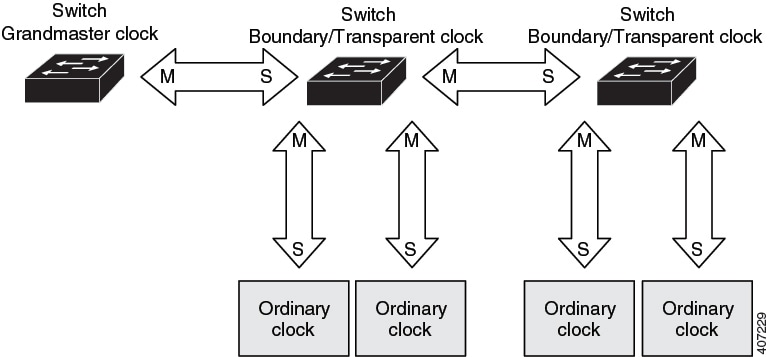
The following figure illustrates PTP clocks in a master-slave hierarchy within a PTP network.
Figure 4. PTP Clock Hierarchy
PTP Profiles
The IEEE 1588 definition of a PTP profile is the set of allowed PTP features applicable to a device . A PTP profile is usually
specific to a particular type of application or environment and defines the following values:
Best master clock algorithm options
Configuration management options
Path delay mechanisms (peer delay or delay request-response)
Range and default values of all PTP configurable attributes and data set members
Closest clock to the grandmaster
Transport mechanisms that are required, permitted, or prohibited
Node types that are required, permitted, or prohibited
Options that are required, permitted, or prohibited
Default Profile
The default PTP profile mode on the switch is Default Profile mode. The PTP mode of transport is Layer 2 and Layer 3.
By default, PTP default profile is disabled globally on these platforms.
How to Configure PTP
Configuring PTP Default Profile
To configure Layer 2 PTP globally, follow these steps:
boundary — mode to enable the switch to participate in selecting the best master clock. If no better clocks are detected, the switch
becomes the grandmaster clock on the network and the parent clock to all connected devices. If the best master is determined
to be a clock connected to the switch, the switch synchronizes to that clock as a child to the clock, then acts as a parent
clock to devices connected to other ports. After initial synchronization, the switch and the connected devices exchange timing
messages to correct time skew caused by clock offsets and network delays. Use this mode when overload or heavy load conditions
produce significant delay jitter
e2etransparent — mode for the switch to synchronize all switch ports with the grand master clock connected to the switch,. This is the default
clock mode. The switch corrects for the delay incurred by every packet passing through it (referred to residence time). This
mode causes less jitter and error accumulation than boundary mode.
p2ptransparent — mode where the switch does not synchronize its clock with the master clock. A switch in this mode does not participate
in master clock selection and uses the default PTP clock mode on all ports.
Note
Once PTP default profile is enabled globally on the device, PTP is enabled on all the interfaces. To disable PTP selectively
on individual interfaces, use no ptp enable command under interface configuration.
Step 4
[no]ptpdomain value
Example:
Device(config)# ptp domain 8
Configures the domain value on PTP.
A single domain value can be set. The range is from 4 to 127. The default value is 0. No ptp domain command will set the
value to default.
Configuring Precision Time Protocol on Layer 2 interface
Procedure
Command or Action
Purpose
Step 1
enable
Example:
Device> enable
Enables privileged EXEC mode.
Enter your password if prompted.
Step 2
configureterminal
Example:
Device configure terminal
Enters global configuration mode.
Step 3
interfaceinterface-id
Example:
Device(config)# interface TenGigabitEthernet1/0/1
Specifies the physical interface to be configured, and enters interface configuration mode. The interface that you specify
can be part of an EtherChannel.
Step 4
[no ]ptp enable
Step 5
ptp vlanvlan-id
Example:
Device(config-if)# ptp vlan 5
Sets the PTP VLAN on a trunk port. The default is the native VLAN of the trunk port. In boundary mode, only PTP packets in
PTP VLAN will be processed, PTP packets from other VLANs will be dropped. Before configuring the PTP VLAN on an interface,
the PTP VLAN must be created and allowed on the trunk port.
Step 6
end
Example:
Device(config-if)# end
Returns to privileged EXEC mode.
Configuring PTP on SVI or Layer 3 Interface
Procedure
Command or Action
Purpose
Step 1
enable
Example:
Device> enable
Enables privileged EXEC mode.
Enter your password if prompted.
Step 2
configureterminal
Example:
Device# configure terminal
Enters global configuration mode.
Step 3
ptp transport ipv4 udp
Example:
Device(config)# ptp transport ipv4 udp
Configures IPv4 as the PTP transport mode.
Note
Only IPv4 is supported as the PTP transport method for Layer 3 PTP.
source address — once configured, ptp messages in all the interfaces will carry this source ip
loopback — ptp messages in all the interfaces will carry the ip configured on the loopback interface
vlan — tp messages will carry the ip configured on the svi interface corresponding to the port.
Note
You can use no ptp source command as default.
Step 4
end
Example:
Device(config-if)# end
Returns to privileged EXEC mode.
Configuring PTP Timers
To change the PTP timer values from default to required values, follow these steps:
Before you begin
Timer inputs are measured in units of log mean message interval value. To determine the value in seconds for the interval keyword, use a logarithmic scale. The following table shows examples of the value keyword converted to seconds with a logarithmic scale:
Value Entered
Logarithmic Calculation
Value in Seconds
-1
2-1
1/2
0
20
1
Procedure
Command or Action
Purpose
Step 1
enable
Example:
Device> enable
Enables privileged EXEC mode.
Enter your password if prompted.
Step 2
configureterminal
Example:
Device# configure terminal
Enters global configuration mode.
Step 3
interfaceinterface-id
Example:
Device(config)# interface gigabitethernet2/0/1
Specifies the physical port to be configured, and enters interface configuration mode.
Step 4
ptp announce {intervalvalue | timeoutcount}
Example:
Device(config-if)# ptp announce interval 1
(Optional) Configures the interval between PTP announce messages on an interface or the number of PTP intervals before a timeout
occurs on an interface.
intervalvalue — Sets the logarithmic mean interval to send announce messages. The range is 0 to 4. The default is 0 (1 second).
timeoutcount — Sets the logarithmic mean interval in seconds to announce timeout messages. The range is 2 to 10. The default is 3 (8 seconds).
Step 5
ptp sync {intervalvalue | limitoffset-value}
Example:
Device(config-if)# ptp sync interval 1
(Optional) Configures the interval between PTP synchronization messages on an interface.
intervalvalue — Sets the logarithmic mean interval to send synchronization messages. The range is –3 to 1. The default is 0 (1 second).
limitoffset-value — Sets the maximum clock offset value before PTP attempts to resynchronize. The range is from 50 to 500000000 nanoseconds.
The default is 500000000 nanoseconds.
Step 6
ptp delay-req intervalvalue
Example:
Device(config-if)# ptp delay-req interval 1
(Optional) Configures the logarithmic mean interval allowed between PTP delay-request messages when the port is in the master
state. The range is 0 to 5. The default is 0 (1 second).
Step 7
ptp pdelay-req intervalvalue
Example:
Device(config-if)# ptp pdelay-req interval 1
(Optional) Configures the logarithmic mean interval allowed between pdelay request messages when the port is in the master
state. The range is 0 to 5. The default is 0 (1 second).
Step 8
end
Example:
Device(config-if)# end
Returns to privileged EXEC mode.
Configuring the Values of Precision Time Protocol Clocks
Follow these steps to configure the values of PTP clock priority1 and priority2:
Procedure
Command or Action
Purpose
Step 1
enable
Example:
Device> enable
Enables privileged EXEC mode.
Enter your password, if prompted.
Step 2
configureterminal
Example:
Device# configure terminal
Enters global configuration mode.
Step 3
ptp priority1value
Example:
Device(config)# ptp priority1 120
Sets the value of PTP clock priority1. The range is from 0 to 255. The default value is 128.
Note
If the value of priority1 is configured as 255, the clock cannot be considered as Grandmaster.
Step 4
ptp priority2value
Example:
Device(config)# ptp priority2 120
Sets the value of PTP clock priority2. The range is from 0 to 255. The default value is 128.
Step 5
exit
Example:
Device(config)# exit
Returns to global configuration mode.
Configuration Examples for PTP
Example: Layer 2 and Layer 3 PTP Configurations
Example
show ptp port interfaceinterface-name
To verify PTP port state, use show ptp port interfaceinterface-name command.
To verify the PTP port states on all interfaces use show ptp brief command.
The following is a sample output for boundary mode configuration with delay request mechanism:
Device# show ptp port GigabitEthernet1/0/45PTP PORT DATASET: GigabitEthernet1/0/45
Port identity: clock identity: 0xCC:46:D6:FF:FE:C5:24:0
Port identity: port number: 45
PTP version: 2
Port state: SLAVE
Delay request interval(log mean): 0
Announce receipt time out: 3
Announce interval(log mean): 1
Sync interval(log mean): 0
Delay Mechanism: End to End
Peer delay request interval(log mean): 0
Sync fault limit: 500000000
The following is a sample output for boundary mode configuration with pdelay request mechanism:
Device# show ptp port GigabitEthernet1/0/45
 PTP PORT DATASET: GigabitEthernet1/0/45
  Port identity: clock identity: 0xCC:46:D6:FF:FE:C5:24:0
  Port identity: port number: 45
  PTP version: 2
  Port state: MASTER
  Delay request interval(log mean): 0
  Announce receipt time out: 3
  Announce interval(log mean): 1
  Sync interval(log mean): 0
  Delay Mechanism: Peer to Peer
  Peer delay request interval(log mean): 0
  Sync fault limit: 500000000
show ptp brief
To verify the PTP port states on all interfaces use show ptp brief command.
The following is a sample output for show ptp brief command:
Device# show ptp briefInterface Domain PTP State
TenGigabitEthernet1/0/1 0 MASTER
TenGigabitEthernet1/0/2 0 SLAVE
TenGigabitEthernet1/0/3 0 FAULTY
show ptp clock
To verify the PTP clock identity details and to verify the configured values of Priority1 and Priority2, use show ptp clock command.
The following is a sample output for show ptp clock command:
Device# show ptp clock
 PTP CLOCK INFO
  PTP Device Type: Boundary clock
  PTP Device Profile: Default Profile
  Clock Identity: 0xCC:46:D6:FF:FE:C5:24:0  <<clock identity of this switch>>
  Clock Domain: 0
  Number of PTP ports: 52
  Priority1: 128
  Priority2: 128
  Clock Quality:
            Class: 248
            Accuracy: Unknown
            Offset (log variance): 16640
  Offset From Master(ns): 0
  Mean Path Delay(ns): 0
  Steps Removed: 1
show ptp parent
To identify which Grandmaster Clock identity the device is synced to in boundary mode, use show ptp parent command.
Note
show ptp parent will not display any output if the device is configured in transparent clock mode.
The following is a sample output for show ptp parent command:
Device# show ptp parent
 PTP PARENT PROPERTIES
  Parent Clock:
  Parent Clock Identity: 0x0:11:1:FF:FE:0:0:1
  Parent Port Number: 1
  Observed Parent Offset (log variance): 16640
  Observed Parent Clock Phase Change Rate: N/A

  Grandmaster Clock:
  Grandmaster Clock Identity: 0x0:11:1:FF:FE:0:0:1     <<Grandmaster clock identity to which the device is synced to>>
  Grandmaster Clock Quality:
            Class: 6
            Accuracy: Within 25ns
            Offset (log variance): 0
            Priority1: 128
            Priority2: 128
show platform software fed switch active ptp domain 0
To verify the local servo PTP clock synchronization to Grandmaster clock on a device configured in boundary mode with delay-request
mechanism, use show platform software fed switch active ptp domain 0 command.
Device# show platform software fed switch active ptp domain 0

Displaying data for domain number 0
============================

Profile Type : DEFAULT
Profile State: enabled
Clock Mode : BOUNDARY CLOCK
Delay mechanism: End-to-End
PTP clock : 2017-6-28 5:58:59
Transport Method: L2 Ethernet
By default, local servo PTP clock will be displaying EPOCH time(1970-1-1) when the device is not synced to any PTP Grandmaster
Clock.
Example
show ptp port interfaceinterface-name
To verify PTP port state, use show ptp port interfaceinterface-name command.
To verify the PTP port states on all interfaces use show ptp brief command.
The following is a sample output for boundary mode configuration with delay request mechanism:
Device# show ptp port FortyGigabitEthernet1/0/10
 PTP PORT DATASET: FortyGigabitEthernet1/0/10
  Port identity: clock identity: 0x0:A3:D1:FF:FE:5A:12:0
  Port identity: port number: 10
  PTP version: 2
  Port state: SLAVE
  Delay request interval(log mean): 0
  Announce receipt time out: 3
  Announce interval(log mean): 1
  Sync interval(log mean): 0
  Delay Mechanism: End to End                                                  << PTP mode delay >>
  Peer delay request interval(log mean): 0
  Sync fault limit: 500000000
show ptp parent
To identify which Grandmaster Clock identity the device is synced to in boundary mode, use show ptp parent command.
Note
show ptp parent will not display any output if the device is configured in transparent clock mode.
The following is a sample output for show ptp parent command:
show platform software fed switch active ptp domain 0
To verify the local servo PTP clock synchronization to Grandmaster clock on a device configured in boundary mode with delay-request
mechanism, use show platform software fed switch active ptp domain 0 command.
Device# show platform software fed switch active ptp domain 0Displaying data for domain number 0
=======================================
Profile Type : DEFAULT
Profile State: enabled
Clock Mode : BOUNDARY CLOCK
Delay Mechanism: : END-TO-END
PTP clock : 2017-12-15 15:27:27
mean_path_delay 214 nanoseconds
Transport Method : udp-ipv4 << PTP Transport Method >>
Table 1. Debug Commands
Command
Purpose
debug ptp messages
Enables debugging of PTP messages.
debug ptp error
Enables debugging of PTP errors.
debug ptp bmc
Enables debugging of the PTP Best Master Clock Algorithm.
debug ptp event
Enables debugging of PTP state event.
Example: Configuring PTP on an EtherChannel Interface
An EtherChannel interface allows multiple physical Ethernet links to combine into one logical channel. Configuring EtherChannel
interface allows load sharing of traffic among the links in the channel as well as redundancy if one or more links in the
EtherChannel fail. This behaviour of an EtherChannel interface does not change when PTP is configured. The example below illustrates
how PTP works when it is configured on an EtherChannel interface.
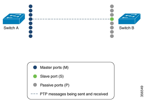
For example, in the figure below there are two switches (Switch A and Switch B) connected through an eight member EtherChannel.
If you consider Switch A as the master clock, all the ports that are a part of the EtherChannel are master ports. Similarly,
Switch B is the slave clock and one of the ports from the EtherChannel bundle becomes the slave port while all other ports
become passive ports. It is always the port with the lowest port number in the Etherchannel bundle that is designated as the
slave port. If that slave port is disabled or shut down for any reason, the next port with the lowest port number is designated
as the slave port.
The master and slave relationship is established when the feature is configured on an EtherChannel interface as well. The
master ports from Switch A sends and receives PTP messages. In Switch B only the slave port exchanges PTP messages. There
is no exchange of PTP messages in the passive ports.
Master Clock
The following command can be used to verify the PTP state on an interface:
Device# show ptp brief | exclude FAULTY
Interface                 Domain     PTP State
TenGigE1/0/39               0         MASTER
TenGigE1/0/44               0         MASTER
TenGigE1/0/48               0         MASTER
The following command can be used to verify if the interface configured on each port is an EtherChannel interface:
Device# show  etherchannel 1  summary
Flags:  D - down        P - bundled in port-channel
        I - stand-alone s - suspended
        H - Hot-standby (LACP only)
        R - Layer3      S - Layer2
        U - in use      f - failed to allocate aggregator

        M - not in use, minimum links not met
        u - unsuitable for bundling
        w - waiting to be aggregated
        d - default port

        A - formed by Auto LAG
Number of channel-groups in use: 3
Number of aggregators:           3

Group  Port-channel  Protocol    Ports
------+-------------+-----------+-----------------------------------------------
1      Po1(SU)         LACP        Hu1/0/39(P)     Hu1/0/44(P)
                                   Hu1/0/48(P)
The following command can be used to verify the port state of each interface:
Device# show ptp port tengigabitethernet 1/0/39
PTP PORT DATASET: TenGigE1/0/39
  Port identity: clock identity: 0x0:A7:42:FF:FE:8A:84:C0
  Port identity: port number: 39
  PTP version: 2
  Port state: MASTER
  Delay request interval(log mean): 0
  Announce receipt time out: 3
  Announce interval(log mean): 0
  Sync interval(log mean): 0
  Delay Mechanism: End to End
  Peer delay request interval(log mean): 0
  Sync fault limit: 500000000

Device# show ptp port tengigabitethernet 1/0/44
PTP PORT DATASET: TenGigE1/0/44
  Port identity: clock identity: 0x0:A7:42:FF:FE:8A:84:C0
  Port identity: port number: 44
  PTP version: 2
  Port state: MASTER
  Delay request interval(log mean): 0
  Announce receipt time out: 3
  Announce interval(log mean): 0
  Sync interval(log mean): 0
  Delay Mechanism: End to End
  Peer delay request interval(log mean): 0
  Sync fault limit: 500000000

Device# show ptp port tengigabitethernet 1/0/48
PTP PORT DATASET: TenGigE1/0/48
  Port identity: clock identity: 0x0:A7:42:FF:FE:8A:84:C0
  Port identity: port number: 48
  PTP version: 2
  Port state: MASTER
 Delay request interval(log mean): 0
  Announce receipt time out: 3
  Announce interval(log mean): 0
  Sync interval(log mean): 0
  Delay Mechanism: End to End
  Peer delay request interval(log mean): 0
  Sync fault limit: 500000000
Slave Clock
The following command can be used to verify the PTP state on the interfaces:
Device# show ptp brief | exclude FAULTY
Interface                       Domain    PTP State
tenGigE1/0/12                     0         SLAVE
TenGigE1/0/20                     0         PASSIVE
TenGigE1/0/23                     0         PASSIVE
The following command can be used to verify if the interface configured on each port is an EtherChannel interface:
Device# show etherchannel 1 summary
Flags:  D - down        P - bundled in port-channel
        I - stand-alone s - suspended
        H - Hot-standby (LACP only)
        R - Layer3      S - Layer2
        U - in use      f - failed to allocate aggregator

        M - not in use, minimum links not met
        u - unsuitable for bundling
        w - waiting to be aggregated
        d - default port
        A - formed by Auto LAG


Number of channel-groups in use: 1
Number of aggregators:           1

Group  Port-channel  Protocol    Ports
------+-------------+-----------+-----------------------------------------------
1      Po1(SU)         LACP        Hu1/0/12(P)     Hu1/0/20(P)
                                   Hu1/0/23(P)
The following command can be used to verify the port state of each interface:
Device# show ptp port tengigabitethernet 1/0/12
PTP PORT DATASET: TenGigE1/0/12
  Port identity: clock identity: 0x0:A7:42:FF:FE:9B:DA:E0
  Port identity: port number: 12
  PTP version: 2
  PTP port number: 12
  PTP slot number: 0
  Port state: SLAVE
  Delay request interval(log mean): 0
  Announce receipt time out: 3
  Announce interval(log mean): 0
  Sync interval(log mean): 0
  Delay Mechanism: End to End
  Peer delay request interval(log mean): 0
  Sync fault limit: 500000000

Device# show ptp port tengigabitethernet 1/0/20
PTP PORT DATASET: TenGigE1/0/20
  Port identity: clock identity: 0x0:A7:42:FF:FE:9B:DA:E0
  Port identity: port number: 20
  PTP version: 2
  PTP port number: 20
  PTP slot number: 0
  Port state: PASSIVE
  Delay request interval(log mean): 0
  Announce receipt time out: 3
  Announce interval(log mean): 0
  Sync interval(log mean): 0
  Delay Mechanism: End to End
  Peer delay request interval(log mean): 0
  Sync fault limit: 500000000

Device# show ptp port tengigabitethernet 1/0/23
PTP PORT DATASET: TenGigE1/0/23
  Port identity: clock identity: 0x0:A7:42:FF:FE:9B:DA:E0
  Port identity: port number: 23
  PTP version: 2
  PTP port number: 23
  PTP slot number: 0
  Port state: PASSIVE
  Delay request interval(log mean): 0
  Announce receipt time out: 3
  Announce interval(log mean): 0
  Sync interval(log mean): 0
  Delay Mechanism: End to End
  Peer delay request interval(log mean): 0
  Sync fault limit: 500000000
Feature History for PTP
This table provides release and related information for features explained in this module.
These features are available on all releases subsequent to the one they were introduced in, unless noted otherwise.
Release
Feature
Feature Information
Cisco IOS XE Fuji 16.8.1a
IEEE 1588v2, Precision Time Protocol (PTP) support
PTP was developed to synchronize the clocks in packet-based networks that include distributed device clocks of varying precisionand
stability.
Support for PTP on Layer 2 ports was introduced.
Support for this feature was introduced only on the C9500-12Q, C9500-16X, C9500-24Q, C9500-40X models of the Cisco Catalyst
9500 Series Switches.
Cisco IOS XE Gibraltar 16.12.1
IEEE 1588v2, Precision Time Protocol (PTP) support
PTP Version 2 (PTPv2) was introduced.
Support for this feature was introduced only on the C9500-32C, C9500-32QC, C9500-48Y4C, and C9500-24Y4C models of the Cisco
Catalyst 9500 Series Switches.
Cisco IOS XE Gibraltar 16.12.1
PTP on native Layer 3 ports
Support for PTP on native Layer 3 ports was introduced.
Support for this feature was introduced on all the models of the Cisco Catalyst 9500 Series Switches.
Cisco IOS XE Amsterdam 17.2.1
IEEE 1588v2 PTP on EtherChannel Interfaces
Support for PTP on an EtherChannel was introduced.
Support for this feature was introduced on all the models of the Cisco Catalyst 9500 Series Switches.
Use Cisco Feature Navigator to find information about platform and software image support. To access Cisco Feature Navigator,
go to http://www.cisco.com/go/cfn.

 Feedback