Cisco Nexus 6000 Series NX-OS Fibre Channel over Ethernet Configuration Guide, Release 7.x
Bias-Free Language
The documentation set for this product strives to use bias-free language. For the purposes of this documentation set, bias-free is defined as language that does not imply discrimination based on age, disability, gender, racial identity, ethnic identity, sexual orientation, socioeconomic status, and intersectionality. Exceptions may be present in the documentation due to language that is hardcoded in the user interfaces of the product software, language used based on RFP documentation, or language that is used by a referenced third-party product. Learn more about how Cisco is using Inclusive Language.
- Updated:
- June 14, 2015
Chapter: Configuring Dynamic FCoE Using DFA
- Information About Dynamic FCoE Using DFA
- Licensing Requirements for Dynamic FCoE Using DFA
- Prerequisites for Dynamic FCoE Using DFA
- Guidelines and Limitations for Dynamic FCoE Using DFA
- Topology Considerations
- Configuration Topology Example
- Configuring Dynamic FCoE Using DFA
- Instantiation and Initialization of Dynamic VFC
- Verifying the Dynamic FCoE Using DFA Configuration
- Configuration Output Examples for Dynamic FCoE Using DFA
Configuring Dynamic FCoE Using DFA
This chapter contains the following sections:
- Information About Dynamic FCoE Using DFA
- Licensing Requirements for Dynamic FCoE Using DFA
- Prerequisites for Dynamic FCoE Using DFA
- Guidelines and Limitations for Dynamic FCoE Using DFA
- Topology Considerations
- Configuration Topology Example
- Configuring Dynamic FCoE Using DFA
- Instantiation and Initialization of Dynamic VFC
- Verifying the Dynamic FCoE Using DFA Configuration
- Configuration Output Examples for Dynamic FCoE Using DFA
Information About Dynamic FCoE Using DFA
Dynamic FCoE Overview
Fibre Channel over Ethernet (FCoE) enables I/O consolidation. It permits both LAN and SAN traffic to coexist on the same switch and the same wire. This feature enables you to consolidate multiple separate networks into a single converged infrastructure.
Key values of I/O consolidation using traditional FCoE are as follows:
-
Elimination of separate network infrastructures for SAN and LAN traffic.
-
Reduction in hardware requirements, such as cabling and server interface cards (NICs and HBAs), and lowering capital expense.
-
Reduction in power and cooling requirements for fewer physical assets.
-
Increasing deployment agility for multiprotocol networks, which preserves long-term investments while preparing for future uncertainty in protocol needs.
By using DFA technology, you can take FCoE consolidation even further:
-
Create a logical, rather than physical, SAN A/B separation.
-
Efficiently load balance multiprotocol traffic within the data center.
-
Dynamically establish relationships between switches, reducing the possibility for human error during configurations.
-
Improved high availability percentages as the scale increases.
The DFA architecture provides an inherent multipath capability with redundancy to handle node failures. Fabric level redundancy is provided through a double fabric model (SAN A/SAN B). The separation of the two SANs is logically implemented as two different VSANs that map to two different VLANs (VLAN A and B). Fibre Channel traffic in SAN A becomes the FCoE traffic in VLAN A, the Fiber Channel traffic in SAN B becomes the FCoE traffic in VLAN B, and the LAN traffic is carried on one or more additional VLANs over the converged Ethernet infrastructure. In this logical environment, the VSAN A/VSAN B configuration protects against fabric-wide control plane failures.
The traditional method of hosts that connect to two separate SANs is still supported with the FCoE using DFA architecture. The host is connected to two different leaf nodes that host a disjointed set of VSANs. Beyond these leaf nodes, the fabric is converged on the same infrastructure, but the host continues to see two SAN fabrics.
The following figure shows a DFA topology with n spines (S) and m leafs (L). The m leafs communicate to each other through the n spines using DFA encapsulation.
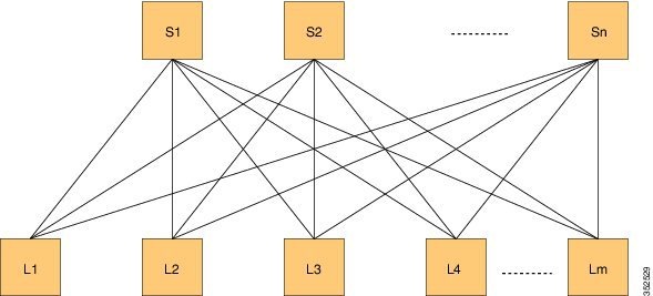
FCoE creates an overlay of FCoE virtual links on top of the underlying Ethernet topology, irrespective of how that Ethernet topology is constructed and which protocol is used to compute the MAC address routes.
In a dynamic FCoE environment, the topology is developed using the leafs as FCoE Forwarder (FCF) switches that are forwarded through transparent spines.
FCoE hosts and FCoE storage devices are connected to a DFA topology through the leaf switches. In this configuration, only the leaf switches perform FCoE forwarding (only the leaf switches behave as FCFs); the spine switches just forward MAC-in-MAC encapsulated Ethernet frames that are based on the outer destination MAC address.
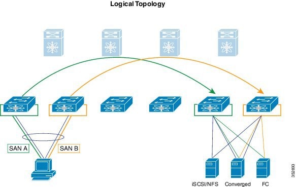
The following figure shows the logical FCoE overlay topology of VE_Port to VE_Port virtual links on a DFA topology.

Only the FCFs, that are implemented by the leaf switches are part of this overlay topology. This topology is seen by Fabric Shortest Path First (FSPF), for each FCoE VLAN. FSPF computes over which virtual link to forward an FCoE frame based on its DomainID (D_ID). A virtual link is uniquely identified by the pair of MAC addresses associated with the two VE_Ports logically connected by it. Identifying the virtual link is equivalent to identifying which MAC addresses to use for the FCoE encapsulation on the transport network.
Use Lm as the number of leafs that are feature enabled. The feature might not be enabled on all leafs. The FCoE mesh is basically the leafs where FCoE is enabled.
Dynamic Fabric Automation Overview
Dynamic Fabric Automation (DFA) is a data center network architecture designed to address the following challenges:
-
Large number of servers hosted with switches/routers requiring huge forwarding tables
-
VM mobility requirements
-
Control plane scaling requirements
-
Simplified management
DFA addresses these requirements by defining a management framework that simplifies provisioning of large networks, a distributed control plane to handle the scale requirements, and an enhanced forwarding paradigm to suppress flooding of control protocols to achieve faster convergence and perform efficient multicasting.
FCoE is a data center technology for storage networks. The FCoE functionality is primarily realized by using FCoE over FabricPath technology. Changes and enhancements have been made to the management aspects of FCoE (POAP/DCNM/Autoconfig) that make it work seamlessly on a DFA network.
It should also be noted that the SAN functionality is not any different from what is available with FCoE over FabricPath networks. All the fibre channel applications and protocols continue to function like classical VE.
A DFA network uses segmentation ID and related protocols in the fabric. Segementation ID based encapsulation is not used for FCoE traffic. FCoE traffic is carried across the DFA fabric using regular FabricPath encapsulation. Dynamic FCoE Using DFA enables the co-existence of DFA and FCoE over FabricPath on the same FCoE DFA leaf nodes. FCoE VLANs are legacy FabricPath VLANs.
- Dynamic Fabric Automation and Fibre Channel Over Ethernet
- Realizing SAN A/B Separation
- Load-Balancing FCoE Traffic on a Dynamic VFC
- Supported Dynamic FCoE Using DFA Topologies
Dynamic Fabric Automation and Fibre Channel Over Ethernet
The key value of Dynamic Fabric Automation (DFA) is the ability for simplified management through DFA. Hundreds of thousands of end points can be provisioned and managed in a simplified and streamlined manner. FCoE fabrics do not have similar scalability requirements. Only a few key configuration capabilities required by FCoE (interface, vlan, vsan, to name a few) are included in DCNM. For additional information about DCNM, see http://www.cisco.com/c/en/us/support/cloud-systems-management/prime-data-center-network-manager/tsd-products-support-series-home.html for details about the FCoE specific changes.
Realizing SAN A/B Separation
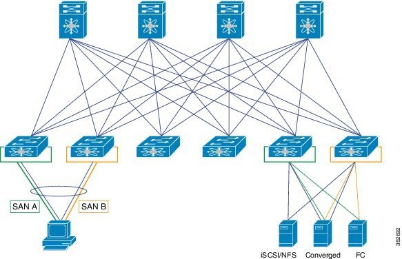
In the previous figure, the physical connectivity for the topology follows typical leaf/spine CLOS architectural best practices. Logically, SAN A and SAN B are isolated at the Top of Rack (ToR) switches physically. Once the traffic enters the DFA network, the storage traffic is logically separated (see the following figure) across the network where it is physically separated once more to the storage device edge.
Dynamic FCoE gains the additional redundancy that is inherent in the DFA network by using the increased spine connectivity. A larger network with a large number of spines means increased reliability and stability for the storage network. This is achieved while retaining the best practices requirements for storage environments.
Load-Balancing FCoE Traffic on a Dynamic VFC
DFA provides redundant paths between a source and destination. Because FCoE traffic traverses the DFA network with one or more FCoE and non-FCoE nodes (spines, leafs), you must ensure in-order delivery through proper port-channel hashing across the redundant paths. All DFA nodes, both leaf and spine, have port-channel hashing enabled that includes the exchange ID. Traffic from a single flow always traverses through only one set of nodes through the network to maintain in-order delivery.
Supported Dynamic FCoE Using DFA Topologies
The supported topologies for Dynamic FCoE Using DFA are as follows:
-
FCoE devices that are directly connected to an FCF leaf
-
Traditional FCoE VE_Port connectivity to an FCF leaf
-
Legacy FC fabric connected to an FCF leaf
-
NPV and FCoE NPV devices that are connected to an FCF leaf
-
Native FC devices that are directly connected to an FCF leaf
 Note | Only classical FCoE is supported on an NPV device that acts as a leaf switch. Dynamic FCoE using DFA is not supported on an NPV leaf switch. |
Licensing Requirements for Dynamic FCoE Using DFA
| Product | License Requirement |
|---|---|
|
Fibre Channel over Ethernet |
Feature FCoE license and feature FabricPath license for the leaf role. |
|
FabricPath |
Feature FabricPath for spine and leaf. |
For more information on DFA Licensing, see http://www.cisco.com/c/en/us/td/docs/switches/datacenter/dfa/licensing/reference/b-dfa-licensing.html.
Prerequisites for Dynamic FCoE Using DFA
Dynamic FCoE prerequisites are as follows:
-
You must enable DFA related features. For more information, see http://www.cisco.com/c/en/us/td/docs/switches/datacenter/dfa/solution/guide/b-dfa-solution-guide.html
-
You must enable feature fcoe for the FCF leafs.
-
You must assign the highest FabricPath cost to the MCT if there is a vPC+ MCT on the FCF leafs.
-
You must enable mode DFA on the VLANs that are mapped to VSANs in all the leaf nodes.
Guidelines and Limitations for Dynamic FCoE Using DFA
Dynamic FCoE Using DFA has the following guidelines and limitations:
-
A spine is supported in transit mode only. Non-transit mode not supported.
-
Feature FCoE should not be enabled on spine nodes.
-
FCoE QoS policies must be explicitly installed on the spine nodes.
-
You must ensure that there is no overlap between Auto-config VLANs and FCoE VLANs. Similarly DFA core VLANs, control VLANs, TF and EF VLANs must be non-overlapping with FCoE VLANs.
-
The Data Center Network Manager (DCNM) provides very basic FCoE configurations. For example, feature enable/disable, VFC (and bound interface), and VSAN-VLAN mapping. The remainder of the SAN configuration must be made manually on the switch.
-
After an upgrade from releases prior to NX-OS 7.0.(1)N1(1), you must perform a reload before you can enable FCoE and FabricPath on the same VLAN.
-
If there are any DFA leaf nodes that do not enable FCoE, you must ensure the following:
-
If there is a VPC+ configuration involving two FCoE DFA nodes, you must ensure that both nodes are on a separate and disjoint set of FCoE FabricPath VLANs. This is in line with the SAN A/B separation requirement for FCoE traffic on a VPC.
-
SPAN support for dynamic VE ports (FCoE over FabricPath links) is not available.
-
SegmentID can still be enabled on the host facing ports of an FCoE DFA leaf where the segmentID VLAN can co-exist with classic FCoE VLANs.
-
DFA does not support multi-topology FabricPath. FCoE using DFA does not support multi-topology.
-
A spine does not need to enable any FCoE VLAN configuration since it is in transit mode and forwards all VLANs.
-
Autoconfig is not enabled for FCoE VLANs. You must ensure that FCoE VLANs are separate from VLANs included under any Autoconfig.
-
In NPV mode leaf, Dynamic FCoE Using DFA is not supported. FCoE over classical Ethernet can co-exist with DFA.
Topology Considerations
The topologies supported by Dynamic FCoE using DFA are the following:
Configuration Topology Example
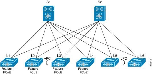
The following figure represents the configuration example that will be described in the following sections.
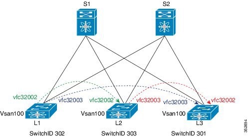
Note | The component labels in the previous diagram are for illustrative purposes only. |
Configuring Dynamic FCoE Using DFA
| Step 1 | Configure all spines. See Configuring All Spines in the DFA Topology. |
| Step 2 | Configure all non-FCF leafs. See Configuring All Non-FCF Leafs in the DFA Topology. |
| Step 3 | Configure all FCF leafs. See Configuring FCF Leafs. |
| Step 4 | Configure ports
on leafs for FC/FCoE.
If vPC or vPC+ is enabled, follow the steps at Increasing the FabricPath Cost for a vPC+ Peer Link for FCF Leafs. |
Configuring All Spines in the DFA Topology
Quality of Service (QoS) settings are enabled on the spine. FCFs are not being established.
This example shows how to configure a spine:
switch# configure terminal
switch(config)# system qos
switch(config)# service-policy type queuing input fcoe-default-in-policy
switch(config)# service-policy type queuing output fcoe-default-out-policy
switch(config)# service-policy type qos input fcoe-default-in-policy
switch(config)# service-policy type network-qos fcoe-default-nq-policy
switch(config)# copy running-config startup-config
Configuring All Non-FCF Leafs in the DFA Topology
Quality of Service (QoS) settings are enabled on the leafs. FCFs are not being established.
| Command or Action | Purpose | |||
|---|---|---|---|---|
| Step 1 | switch# configure terminal |
Enters global configuration mode. | ||
| Step 2 | switch(config)# install feature-set fabricpath |
Installs the FabricPath feature set on the switch. | ||
| Step 3 | switch(config)# feature-set fabricpath |
Enables the FabricPath feature set on the switch. | ||
| Step 4 | switch(config)# system qos |
Enters system class configuration mode. | ||
| Step 5 | switch(config-sys-qos)# service-policy type {network-qos | qos | queuing} [input | output] fcoe-default-policy-name |
Sets up the service policy for the system to specify the default policy map for FCoE traffic. Four predefined policy-maps for FCoE are as follows:
| ||
| Step 6 | switch(config-sys-qos)# vlan vlan-id |
Enters VLAN configuration mode. The VLAN number range is from 1 to 4096. | ||
| Step 7 | switch(config-vlan)# mode fabricpath |
Configures the VLANs as FabricPath VLANs. Configure the VLANs as FabricPath VLANs for all the FCoE over FabricPath VLANs of other FCF leafs. | ||
| Step 8 | switch(config-vlan)# interface [ethernet slot/port | port-channel channel-no] |
Enters interface configuration mode and specifies the interfaces that you want to configure as FabricPath. The port number within a particular slot can be from 1 to 128. The port channel number assigned to the EtherChannel logical interface can be from 1 to 4096. | ||
| Step 9 | switch(config-if)# switchport mode fabricpath |
Specifies interfaces as FabricPath ports. | ||
| Step 10 | switch(config-if)# copy running-config startup-config | (Optional)
Saves the change persistently through reboots and restarts by copying the running configuration to the startup configuration. |
This example shows how to configure a leaf:
switch# configure terminal
switch(config)# install feature-set fabricpath
switch(config)# feature-set fabricpath
switch(config)# system qos
switch(config)# service-policy type queuing input fcoe-default-in-policy
switch(config)# service-policy type queuing output fcoe-default-out-policy
switch(config)# service-policy type qos input fcoe-default-in-policy
switch(config)# service-policy type network-qos fcoe-default-nq-policy
switch(config)# vlan 10
switch(config-vlan)# mode fabricpath
switch(config-vlan)# interface ethernet1/11
switch(config-if)# switchport mode fabricpath
switch(config-if)# copy running-config startup-config
Configuring FCF Leafs
| Command or Action | Purpose | |||
|---|---|---|---|---|
| Step 1 | switch# configure terminal |
Enters global configuration mode. | ||
| Step 2 | switch(config)# feature fcoe |
Enables the FCoE capability. | ||
| Step 3 | switch(config)# fcoe fka-adv-period interval |
Configures the advertisement interval for the fabric. The default value is 8 seconds. The range is from 4 to 60 seconds. The interval must be set to a minimum of 20 seconds for Dynamic FCoE Using DFA to work correctly. | ||
| Step 4 | switch(config)# fabricpath switch-id switch-id-value |
Configures the switch ID. The range is from 1 to 4094. | ||
| Step 5 | switch(config)# vlan vlan-id |
Enters VLAN configuration mode. The VLAN number range is from 1 to 4096. | ||
| Step 6 | switch(config)# vsan database |
Enters VSAN configuration mode. | ||
| Step 7 | switch(config-vsan-db)# vsan vsan-id |
Configures VSAN. | ||
| Step 8 | switch(config-vsan-db)# show vpc |
Displays information about the vPC.
| ||
| Step 9 | switch(config)# copy running-config startup-config | (Optional)
Saves the change persistently through reboots and restarts by copying the running configuration to the startup configuration. |
This example shows how to configure FCF leafs:
switch# configure terminal
switch(config)# feature fcoe
switch(config)# fcoe fka-adv-period 20
switch(config)# fabricpath switch-id 5
switch(config)# vlan 100
switch(config-vsan-db)# vsan database
switch(config-vsan-db)# vsan 100
switch(config-vsan-db)# show vpc
Configuring VLANs to be FCoE and DFA Enabled
| Command or Action | Purpose | |
|---|---|---|
| Step 1 | switch# configure terminal |
Enters global configuration mode. |
| Step 2 | switch(config)# vlan vlan-id |
Enters VLAN configuration mode. The VLAN number range is from 1 to 4096. |
| Step 3 | switch(config-vlan)# fcoe [vsan vsan-id] |
Enables FCoE for the specified VLAN. If you do not specify a VSAN number, a mapping is created from this VLAN to the VSAN with the same number. Configures the mapping from this VLAN to the specified VSAN. |
This example shows how to configure FCoE and DFA-Enabled VLANs:
switch# configure terminal
switch(config)# vlan 100
switch(config-vlan)# fcoe vsan 10
Defining DFA VLANs
| Command or Action | Purpose | |||
|---|---|---|---|---|
| Step 1 | switch# configure terminal |
Enters global configuration mode. | ||
| Step 2 | switch(config)# vlan vlan-id |
Enter VLAN configuration mode. The VLAN number range is from 1 to 4096. | ||
| Step 3 | switch(config-vlan)# mode fabricpath |
Configures the operational mode of the VLAN.
| ||
| Step 4 | switch(config-vlan)# copy running-config startup-config |
Saves the change persistently through reboots and restarts by copying the running configuration to the startup configuration. |
This example shows how to define a DFA VLAN:
switch# configure terminal
switch(config)# vlan 100
switch(config-vlan)# mode fabricpath
switch(config-vlan)# copy running-config startup-config
Increasing the DFA Cost for a vPC+ Peer Link for FCF Leafs
| Command or Action | Purpose | |
|---|---|---|
| Step 1 | switch# configure terminal |
Enters global configuration mode. |
| Step 2 | switch(config)# show vpc |
Based on the output of the show vpc command, you have three options: |
| Step 3 | switch(config)# interface [ethernet slot/port | port-channel channel-no] |
Enters interface configuration mode and specifies the interfaces that you want to configure as FabricPath. The port number within a particular slot can be from 1 to 128. The port channel number assigned to the EtherChannel logical interface can be from 1 to 4096. |
| Step 4 | switch(config-if)# fabricpath isis metric default-metric |
Configures the metric for the MCT interface. You must set the default-metric to 16777215. |
| Step 5 | switch(config-if)# copy running-config startup-config | (Optional)
Saves the change persistently through reboots and restarts by copying the running configuration to the startup configuration. |
This example shows how to increase the DFA for a vPC+ peer link:
switch# configure terminal
switch(config)# show vpc
switch(config)# interface ethernet 1/11
switch(config-if)# fabricpath isis metric 16777210
Instantiation and Initialization of Dynamic VFC
Dynamic FCoE enables the capability of creating both a virtual Fibre Channel port (VFC), as well as instantiating the Inter-Switch Link port type (VE_Port/TE Port). Enabling FCoE and DFA on the same VLAN should serve as a trigger to instantiation and initialization of the Dynamic VFCs in TE mode. The process is as follows:
-
Every FCF leaf is uniquely identified by a global FCF-MAC address.
-
Every FCF leaf floods an FIP unsolicited multicast discovery advertisement to ALL-FCF MAC addresses and source MAC addresses that are set to its global FCF-MAC address on the DFA-enabled FCoE VLANs. This is triggered by two factors:
-
All FCF leafs on this DFA cloud should receive this multicast advertisement on the corresponding FCoE-enabled FP VLAN. Upon receiving this FIP multicast frame, a dynamic VFC in VE mode is created between the two FCF leaf nodes.
-
Only one dynamic VFC in TE mode is between any two FCF leafs.
-
The dynamic VFCs can be differentiated based on their VFC ID range. All dynamic VFCs obtain an ID that is greater than 32000.
-
The VFC might have multiple DFA FCoE VLANs up. The VLANs might or might not be in the same topology.
-
Every FCF leaf is one hop away. For all VE paths that use DFA, a default fixed FSPF cost value is used.
Verifying the Dynamic FCoE Using DFA Configuration
To display Dynamic FCoE using DFA configuration information, perform one of the following tasks:
| Command | Purpose |
|---|---|
|
show interface brief |
Displays a brief summary of the interface configuration information. |
|
show interface vfc |
Displays the configuration information of virtual Fibre Channel interfaces. |
|
show vpc |
Displays the configuration information of virtual port channels. See show vpc Command |
|
show topology |
Displays topology information for connected SAN switches. |
|
show fcoe |
Displays the status of FCoE parameters on the switch. |
|
show running-config |
Displays the configuration that is currently running on the switch. |
|
show fcoe dce |
Displays the Dynamic FCoE database using FabricPath. |
show interface brief Command
switch(config)# show interface brief
--------------------------------------------------------------------------------
Ethernet      VLAN    Type Mode   Status  Reason                   Speed     Por
t
Interface                                                                    Ch
#
--------------------------------------------------------------------------------
Eth1/1        1       eth  access up      none                        10G(D) --
Eth1/2        1       eth  access down    Link not connected          10G(D) --
Eth1/3        1       eth  access up      none                        10G(D) --
Eth1/4        1       eth  access up      none                        10G(D) --
Eth1/5        1       eth  access up      none                        10G(D) --
Eth1/6        1       eth  access up      none                        10G(D) --
Eth1/7        1       eth  access up      none                        10G(D) --
Eth1/8        1       eth  access down    SFP not inserted            10G(D) --
Eth1/9        1       eth  access down    SFP validation failed       10G(D) --
Eth1/10       1       eth  access down    SFP not inserted            10G(D) --
Eth1/11       1       eth  f-path up      none                        10G(D) --
Eth1/12       1       eth  access down    SFP not inserted            10G(D) --
Eth1/13       1       eth  access up      none                        10G(D) --
Eth1/14       1       eth  access up      none                        10G(D) --
Eth1/15       1       eth  access down    SFP validation failed       10G(D) --
Eth1/16       1       eth  access down    Link not connected          10G(D) --
Eth1/17       1       eth  access up      none                        10G(D) --
Eth1/18       1       eth  access up      none                        10G(D) --
Eth1/19       1       eth  access down    SFP validation failed       10G(D) --
Eth1/20       1       eth  access up      none                        10G(D) --
Eth1/21       1       eth  access down    SFP validation failed       10G(D) --
Eth1/22       1       eth  access up      none                        10G(D) --
Eth1/23       1       eth  access down    SFP validation failed       10G(D) --
Eth1/24       1       eth  access down    SFP not inserted            10G(D) --
Eth1/25       1       eth  access up      none                        10G(D) --
Eth1/26       1       eth  access up      none                        10G(D) --
Eth1/27       1       eth  access up      none                        10G(D) --
Eth1/28       1       eth  access up      none                        10G(D) --
Eth1/29       1       eth  access up      none                        10G(D) --
Eth1/30       1       eth  access down    SFP not inserted            10G(D) --
Eth1/31       1       eth  access down    SFP not inserted            10G(D) --
Eth1/32       1       eth  access down    SFP not inserted            10G(D) --

--------------------------------------------------------------------------------
Port   VRF          Status IP Address                              Speed    MTU
--------------------------------------------------------------------------------
mgmt0  --           up     10.193.52.117                           1000     1500

-------------------------------------------------------------------------------
Interface  Vsan   Admin  Admin   Status      Bind                 Oper    Oper
                  Mode   Trunk               Info                 Mode    Speed
                         Mode                                            (Gbps)
-------------------------------------------------------------------------------
vfc32002   1      E     on     trunking    54:7f:ee:b1:8a:00        TE   10
vfc32003   1      E     on     trunking    54:7f:ee:73:e8:00        TE   10
show interface vfc Command
switch(config)# show interface vfc 32002
vfc32002 is trunking
    Dynamic VFC Peer MAC is 54:7f:ee:b1:8a:00
    Hardware is Ethernet
    Port WWN is 2d:01:54:7f:ee:73:e6:78
    Admin port mode is E, trunk mode is on
    snmp link state traps are enabled
    Port mode is TE
    Port vsan is 1
    Trunk vsans (admin allowed and active) (1,100)
    Trunk vsans (up)                       (100)
    Trunk vsans (isolated)                 ()
    Trunk vsans (initializing)             (1)
    1 minute input rate 0 bits/sec, 0 bytes/sec, 0 frames/sec
    1 minute output rate 0 bits/sec, 0 bytes/sec, 0 frames/sec
      0 frames input, 0 bytes
      0 frames output, 0 bytes
    Interface last changed at Mon Feb 14 19:46:53 2011

switch(config)# show interface vfc 32003
vfc32003 is trunking
    Dynamic VFC Peer MAC is 54:7f:ee:73:e8:00
    Hardware is Ethernet
    Port WWN is 2d:02:54:7f:ee:73:e6:78
    Admin port mode is E, trunk mode is on
    snmp link state traps are enabled
    Port mode is TE
    Port vsan is 1
    Trunk vsans (admin allowed and active) (1,100)
    Trunk vsans (up)                       (100)
    Trunk vsans (isolated)                 ()
    Trunk vsans (initializing)             (1)
    1 minute input rate 0 bits/sec, 0 bytes/sec, 0 frames/sec
    1 minute output rate 0 bits/sec, 0 bytes/sec, 0 frames/sec
      0 frames input, 0 bytes
      0 frames output, 0 bytes
    Interface last changed at Mon Feb 14 19:49:23 2011


===========================================================================
show vpc Command
switch(config)# show vpc
			vPC domain id : 300 vPC+ switch id : 1550
   vPC Peer-link status
   ---------------------------------------------------------------------
   id   Port   Status Active vlans
   --   ----   ------ --------------------------------------------------
   1   Po1    up     -
show topology Command
switch(config)# show topology
FC Topology for VSAN 100 :
--------------------------------------------------------------------------------
       Interface  Peer Domain Peer Interface     Peer IP Address(Switch Name)
--------------------------------------------------------------------------------
         vfc32002  0x0b(11)         vfc32002  10.193.52.108(nc-9)
         vfc32003 0x64(100)         vfc32003  10.193.52.118(o2-356)
show fcoe Command
switch(config)# show fcoe
Global FCF details
        FCF-MAC is 54:7f:ee:73:e6:20
        FC-MAP is 0e:fc:00
        FCF Priority is 128
        FKA Advertisement period for FCF is 20 seconds

VFC MAC details
show running-config Command
switchconfig)# show running-config

!Command: show running-config
!Time: Mon Feb 14 19:58:47 2011

version 7.0(3)N1(1)
feature fcoe

install feature-set fabricpath
feature-set fabricpath

feature telnet
feature lldp

username admin password 5 $1$1dLADwhf$7Ip2IYSMp/0nsII8rU5qh/  role network-admin
no password strength-check
ip domain-lookup
system qos
  service-policy type qos input fcoe-default-in-policy
  service-policy type queuing input fcoe-default-in-policy
  service-policy type queuing output fcoe-default-out-policy
  service-policy type network-qos fcoe-default-nq-policy
snmp-server user admin network-admin auth md5 0x95d13d5b1da2ee92b77769b4c177a94b
 priv 0x95d13d5b1da2ee92b77769b4c177a94b localizedkey
rmon event 1 log trap public description FATAL(1) owner PMON@FATAL
rmon event 2 log trap public description CRITICAL(2) owner PMON@CRITICAL
rmon event 3 log trap public description ERROR(3) owner PMON@ERROR
rmon event 4 log trap public description WARNING(4) owner PMON@WARNING
rmon event 5 log trap public description INFORMATION(5) owner PMON@INFO

vlan 1
vlan 100
  fcoe vsan 100
  mode fabricpath
vrf context management
  ip route 0.0.0.0/0 10.193.48.1
vsan database
  vsan 100


interface vfc32002
  bind mac-address 54:7f:ee:b1:8a:00
  dce
  switchport mode E
  no shutdown

interface vfc32003
  bind mac-address 54:7f:ee:73:e8:00
  dce
  switchport mode E
  no shutdown

interface Ethernet1/1

interface Ethernet1/2

interface Ethernet1/3

interface Ethernet1/4

interface Ethernet1/5

interface Ethernet1/6

interface Ethernet1/7

interface Ethernet1/8

interface Ethernet1/9

interface Ethernet1/10

interface Ethernet1/11
  switchport mode fabricpath

interface Ethernet1/12

interface Ethernet1/13

interface Ethernet1/14

interface Ethernet1/15

interface Ethernet1/16

interface Ethernet1/17

interface Ethernet1/18

interface Ethernet1/19

interface Ethernet1/20

interface Ethernet1/21

interface Ethernet1/22

interface Ethernet1/23

interface Ethernet1/24

interface Ethernet1/25

interface Ethernet1/26

interface Ethernet1/27

interface Ethernet1/28

interface Ethernet1/29

interface Ethernet1/30

interface Ethernet1/31

interface Ethernet1/32

interface mgmt0
  vrf member management
  ip address 10.193.52.117/21
line console
line vty
fabricpath domain default
fabricpath switch-id 302
show fcoe dce Command
switch# show fcoe dce

Dynamic VFC MAC details :
-----------------------------------------------------------
   Interface    Peer-swid       Peer-mac
-----------------------------------------------------------
   vfc32002     303             54:7f:ee:b1:8a:00
   vfc32003     301             54:7f:ee:73:e8:00
Configuration Output Examples for Dynamic FCoE Using DFA
The following output examples show how to configure Dynamic FCoE using DFA. You must enter the feature fabricpath command and configure the appropriate links as FabricPath core ports.
This example covers VSAN 100 and VSAN 200.
The following is a description of the topology example:
-
S1 and S2 are FabricPath spines in transit mode.
-
L1 through L4 are FCF leafs.
-
L5 and L6 are non-FCoE leafs.
This example shows the configuration on S1 and S2:
switch# show running-config
system qos
  service-policy type qos input fcoe-default-in-policy
  service-policy type queuing input fcoe-default-in-policy
  service-policy type queuing output fcoe-default-out-policy
  service-policy type network-qos fcoe-default-nq-policy
This example shows the configuration on L5 and L6 non-FCoE leafs:
switch# show running-config
system qos
  service-policy type qos input fcoe-default-in-policy
  service-policy type queuing input fcoe-default-in-policy
  service-policy type queuing output fcoe-default-out-policy
  service-policy type network-qos fcoe-default-nq-policy
vlan 100
   mode fabric path
vlan 200
   mode fabric path
This example shows the configuration on L1 - FCF leaf (VSAN 100)
switch# show running-config
feature fcoe
vlan 100
    mode fabric path
    fcoe vsan 100
vlan 200
     mode fabric path

vsan database
     vsan 100

fabricpath switch-id 301

fcoe fka-adv-period  20
This example shows the configuration on the L4 FCF leaf (VSAN 100, VSAN 200):
switch# show running-config
feature fcoe
vlan 100
    mode fabric path
    fcoe vsan 100
vlan 200
     mode fabric path
     fcoe vsan 200
vsan database
     vsan 100
     vsan 200

fabricpath switch-id  304

fcoe fka-adv-period 20
This example shows the configuration on the L2 FCF leaf (VSAN 100):
switch# show running-config
feature fcoe

vlan 100
    mode fabric path
    fcoe vsan 100
vlan 200
     mode fabric path

vsan database
     vsan 100

fabricpath switch-id 302

fcoe fka-adv-period 20

switch# show vpc
vPC domain id                     : 1
vPC+ switch id                    : 123

:
vPC Peer-link status
-----------------------------------------------------------
id Port Status Active vlans
-- ---- ------ --------------------------------------------
1  Po93 up     1,10,20,30,101,201,500
interface port-channel93
           fabricpath isis metric 16777215
This example shows the configuration on the L3 FCF leaf (VSAN 200):
switch# show running-config
feature fcoe

vlan 100
    mode fabric path

vlan 200
     mode fabric path
     fcoe vsan 200
vsan database
     vsan 200

fabricpath switch-id 303

fcoe fka-adv-period 20

switch# show vpc
vPC domain id        : 1
vPC+ switch id       : 123

:
-----------------------------------------------------------
id Port Status Active vlans
-- ---- ------ --------------------------------------------
1  Po93 up     1,10,20,30,101,201,500
interface port-channel93
  fabricpath isis metric 16777215
 Feedback