Cisco IT ACI Storage Deployment
Available Languages
This white paper presents a case study of the Cisco IT ACI NetApp storage area network deployment. This series of case studies explains how Cisco IT deployed Cisco ACI to deliver improved business performance. Other case studies in this series cover the Cisco IT ACI data center design, migration to Cisco ACI, network security, and virtualization with AVS, UCS, KVM, and VMware. These white papers will enable field engineers and customer IT architects to assess the product, plan deployments, and exploit its application centric properties to flexibly deploy and manage robust highly scalable integrated data center and network resources.
Version: 1.1, June 15, 2020 – updated with copy edits for clarity.
Americas Headquarters
Cisco Systems, Inc.
170 West Tasman Drive
San Jose, CA 95134-1706
USA
Tel: 408 526-4000
800 553-NETS (6387)
Fax: 408 527-0883
THE SPECIFICATIONS AND INFORMATION REGARDING THE PRODUCTS IN THIS MANUAL ARE SUBJECT TO CHANGE WITHOUT NOTICE. ALL STATEMENTS, INFORMATION, AND RECOMMENDATIONS IN THIS MANUAL ARE BELIEVED TO BE ACCURATE BUT ARE PRESENTED WITHOUT WARRANTY OF ANY KIND, EXPRESS OR IMPLIED. USERS MUST TAKE FULL RESPONSIBILITY FOR THEIR APPLICATION OF ANY PRODUCTS.
THE SOFTWARE LICENSE AND LIMITED WARRANTY FOR THE ACCOMPANYING PRODUCT ARE SET FORTH IN THE INFORMATION PACKET THAT SHIPPED WITH THE PRODUCT AND ARE INCORPORATED HEREIN BY THIS REFERENCE. IF YOU ARE UNABLE TO LOCATE THE SOFTWARE LICENSE OR LIMITED WARRANTY, CONTACT YOUR CISCO REPRESENTATIVE FOR A COPY.
The Cisco implementation of TCP header compression is an adaptation of a program developed by the University of California, Berkeley (UCB) as part of UCB's public domain version of the UNIX operating system. All rights reserved. Copyright © 1981, Regents of the University of California.
NOTWITHSTANDING ANY OTHER WARRANTY HEREIN, ALL DOCUMENT FILES AND SOFTWARE OF THESE SUPPLIERS ARE PROVIDED "AS IS" WITH ALL FAULTS. CISCO AND THE ABOVE-NAMED SUPPLIERS DISCLAIM ALL WARRANTIES, EXPRESSED OR IMPLIED, INCLUDING, WITHOUT LIMITATION, THOSE OF MERCHANTABILITY, FITNESS FOR A PARTICULAR PURPOSE AND NONINFRINGEMENT OR ARISING FROM A COURSE OF DEALING, USAGE, OR TRADE PRACTICE.
IN NO EVENT SHALL CISCO OR ITS SUPPLIERS BE LIABLE FOR ANY INDIRECT, SPECIAL, CONSEQUENTIAL, OR INCIDENTAL DAMAGES, INCLUDING, WITHOUT LIMITATION, LOST PROFITS OR LOSS OR DAMAGE TO DATA ARISING OUT OF THE USE OR INABILITY TO USE THIS MANUAL, EVEN IF CISCO OR ITS SUPPLIERS HAVE BEEN ADVISED OF THE POSSIBILITY OF SUCH DAMAGES.
Any Internet Protocol (IP) addresses and phone numbers used in this document are not intended to be actual addresses and phone numbers. Any examples, command display output, network topology diagrams, and other figures included in the document are shown for illustrative purposes only. Any use of actual IP addresses or phone numbers in illustrative content is unintentional and coincidental.
This product includes cryptographic software written by Eric Young (eay@cryptsoft.com).
This product includes software developed by the OpenSSL Project for use in the OpenSSL Toolkit. (http://www.openssl.org/) This product includes software written by Tim Hudson (tjh@cryptsoft.com).
Cisco and the Cisco logo are trademarks or registered trademarks of Cisco and/or its affiliates in the U.S. and other countries. To view a list of Cisco trademarks, go to this URL: http:// www.cisco.com/go/trademarks. Third-party trademarks mentioned are the property of their respective owners. The use of the word partner does not imply a partnership relationship between Cisco and any other company. (1110R)
© 2020 Cisco Systems, Inc. All rights reserved
Table of Contents
Cisco IT ACI Storage Deployment
Where Storage Fits in Cisco IT ACI Fabric Infrastructure
Cisco IT ACI Storage Deployment
The Cisco® IT ACI storage solution uses the all flash version of NetApp clustered data on tap (cDOT). Cisco ACI enables lower latency higher bandwidth data access, and easier east-west workload mobility within the fabric. Cisco ACI uses a common application-aware policy-based operating model across their physical and virtual environments that enables Cisco IT to more easily manage integrated resource pools of compute, storage, and networking within virtual boundaries.
Joe DeSanto, Cisco IT Storage Architect explains:
"One of the unique design opportunities in Cisco ACI is for us to realize the potential for improved storage performance and mobility in the east – west Cisco ACI model compared with the traditional north – south model."
The Cisco ACI spine leaf architecture enables a significant performance improvement because endpoint to endpoint communication across the fabric is no more than a single hop. Also, any storage solution can take advantage of the high bandwidth connectivity of the Cisco ACI Nexus 9000 Series switches. Provisioning dedicated leaf switches for storage enables the Cisco ACI NetApp cDOT solution to balance and migrate storage workloads across leaf switch pairs without disrupting workloads. This white paper details how Cisco IT designed its Cisco ACI storage deployment to do just that.
Where Storage Fits in Cisco IT ACI Fabric Infrastructure
While standardization and reuse as a data center design strategy is not new, provisioning data center infrastructure according to software defined standardized constructs is transformative. The combination of standardized data center Cisco ACI fabric topologies and software defined standardized constructs enables seamless dynamic provisioning of any data center workload anywhere.
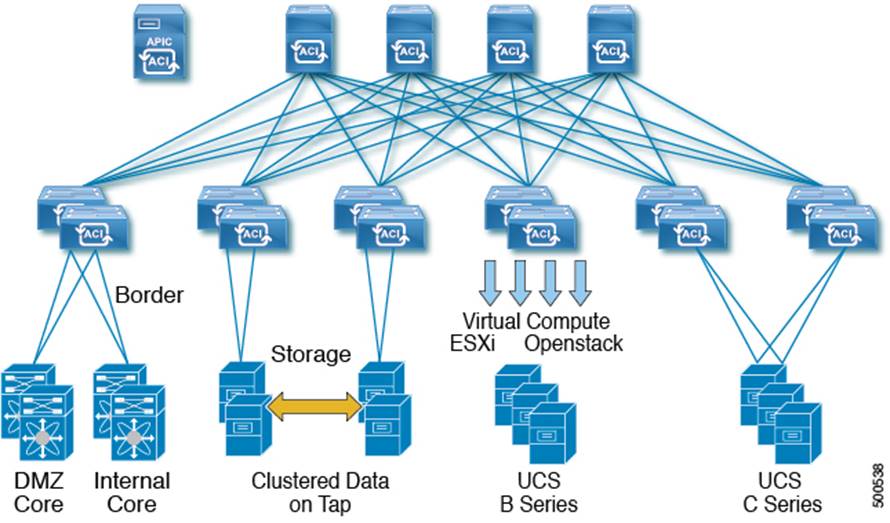
The Cisco IT ACI standard data center (DC) has four spine switches, one pair of border leaf switches for external connectivity, two or more pairs of leaf switches for endpoint connectivity, and the minimum supported number of three Cisco APICs.
Standard Data Center
Cisco IT ACI vPC Connectivity Templates
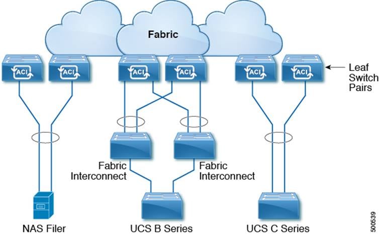
Connecting devices such as a NAS filer or UCS Fabric Interconnect to a leaf switch pair using a vPC provides increased resiliency and redundancy. Unlike a vPC on the Nexus 5/6/7K platforms, an Cisco ACI vPC leaf switch pair does not need direct physical connectivity peer links to each other.
The Cisco IT standardized compute and storage pod templates enable applications to flexibly tap into any available compute or storage resources. Storage leaf switch pairs are in a horizontal distribution area (HDA) where the servers connect directly to them via 10 gigabit Ethernet.
Each UCS B series domain has dual fabric interconnects (A and B side), with each FI having four 10GE uplinks, spread equally between the two leaf switches in the pod pair. The links are setup in vPC mode and both FIs are active. This arrangement provides a total of 80Gbps for every UCS cluster. New applications and solutions that follow a horizontal scale out philosophy such as Hadoop and Ceph storage are driving a new type of pod where the goal is to have as many UCS C series servers has possible within a rack. In this topology, the C series servers connect directly to the Cisco ACI leaf switches.
Cisco's NetApp NAS implementation uses the FAS80xx all flash Clustered Data ONTAP (cDOT) virtual arrays which are presented to a variety of hosts, including Cisco Enterprise Linux (CEL) hosts, VMware ESXi virtual machines, and Windows systems. NetApp storage efficiency features such as de-duplication are widely used at Cisco. Cisco has multiple copies of several moderate to large Oracle databases aligned into development tracks. These instances today occupy multiple Petabytes (PB) of storage, consuming a large amount of the data center resources in Research Triangle Park, NC (RTP), Richardson, TX (RCDN), and Allen, TX (ALLN).
The change from 7-Mode NAS to cDOT allows a filer IP to failover between two physical NAS filer heads; the IP can failover to any head or node within the cluster. Cisco ACI VXLAN enables greater flexibility regarding the IP addresses linked to the IP cDOT storage systems. The IP addresses can be active anywhere on the cDOT cluster in the Cisco ACI fabric. If an Cisco ACI leaf switch or a cDOT node fails, the IP addresses can move to different Cisco ACI leaf switches and cDOT nodes.
Cisco IT moved from a filer per pod NAS model to a consolidated and centralized NAS model. NAS filers are connected to dedicated leaf switch pairs.
NetApp cDOT Storage Cluster Template
Each filer head has a primary link made up of four 10GE interfaces in a virtual port channel (two 10GE to each leaf switch in the pair).
The NetApp Clustered Data ONTAP (cDOT) cluster is a high performance, resilient, virtual storage array that abstracts data access (networking – SAN and NAS) and data layout (volumes and LUNs) from the client. A cDOT cluster is anywhere from one to twelve highly available storage pairs (SAN = 8 nodes max; NAS = 24 nodes max) connected via a high-speed low-latency private fabric (aka Cluster Interconnect). Creating a cluster enables the nodes to pool their resources and distribute work across the cluster, while presenting administrators with a single entity to manage. Clustering also enables continuous service to end users if individual nodes go offline.
The nodes in a cluster communicate over a dedicated, physically isolated, dual-fabric and secure Ethernet network. Two node pairs within the clusters are configured with cluster high availability (HA). cDOT clusters can be maintained with non-disruptive hardware tech refresh operations. This includes but is not limited to the live replacement of cluster nodes while a workload is present on the cDOT cluster. The ability to perform non-disruptive hardware or controller replacement on a cDOT cluster with a live workload is key to Cisco IT's refresh cycle. This ability to do non-disruptive replacement enables Cisco IT to meet and exceed service level agreement (SLA) metrics.
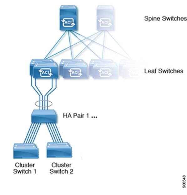
Cisco IT ACI Production NetApp cDOT Storage Cluster
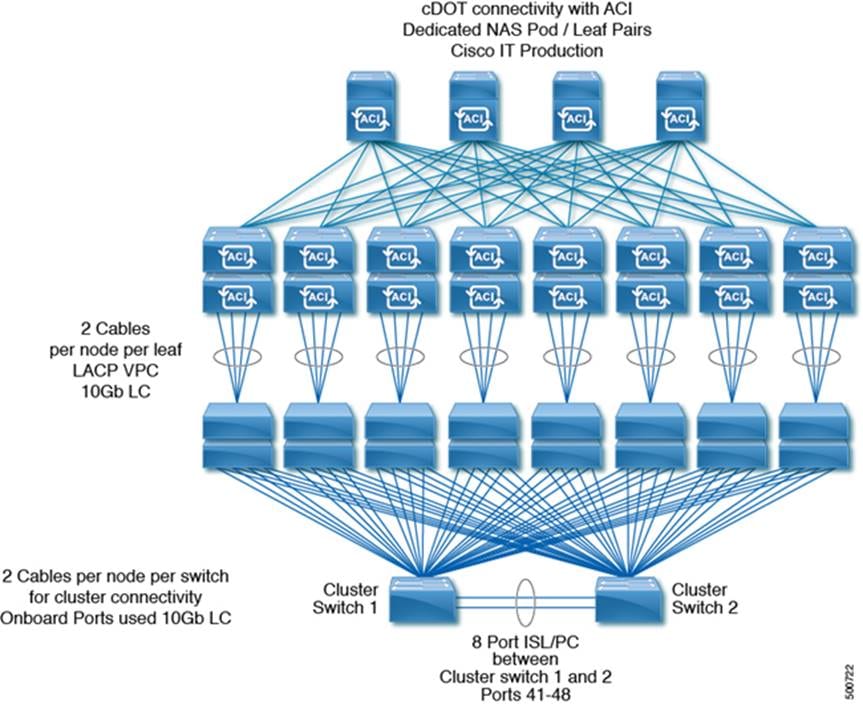
Note: While the NetApp scalability numbers are higher, Cisco IT deploys up to 8 HA pairs (16 nodes) per cDOT cluster, and up to 10 HA pairs (20 nodes) per cDOT cluster during node refreshes.
Nodes are connected in an alternating fashion:
· HA Pair 1 and 3 connect to the first leaf switch pair (e.g. switch 1011 and 1012)
· HA Pair 2 and 4 connect to the second leaf switch pair (e.g. switch 1021 and 1022)
· HA Pair 5 and 7 connect to the third leaf switch pair (e.g. switch 1031 and 1032)
· HA Pair 6 and 8 connect to the fourth leaf switch pair (e.g. switch 1041 and 1042)
· HA Pair 9 and 11 connect to the fifth leaf switch pair (e.g. switch 1051 and 1052)
· HA Pair 10 and 12 connect to the sixth leaf switch pair (e.g. switch 1061 and 1062)
Note that all switch numbers above are just examples, but in all cases no more than 2 HA pairs per cluster connect to a pair of leaf switches.
L2 Interface Groups
An interface group is a NetApp cDOT feature that implements link aggregation on the storage system. Interface groups aggregate multiple network interfaces into one logical interface. After an interface group is created, it is indistinguishable from a physical network interface.
· All NetApp controller Node NICs shown above are 10gigE
· Each cDOT node is connected to 2 leaf switches, using 2 x 10GE per switch, using vPC across each leaf pair – this gives provides 40 gigabits / sec (4 x 10gigE) of active/active redundant links for each node
The cluster logical interfaces (LIFs) on each node in the cluster must be on the same subnet.
The Cisco® IT deployment of Cisco ACI with NetAPP cDOT IP storage enables lower latency higher bandwidth data access, and optimized east-west mobility within the fabric. Cisco ACI uses a common application-aware policy-based operating model across their physical and virtual environments that enables Cisco IT to more easily manage integrated resource pools of compute, storage, and network within virtual boundaries.
 Feedback
Contact Cisco
- Open a Support Case

- (Requires a Cisco Service Contract)