Cisco ACI Policy Model Guide
About the Cisco Application Centric Infrastructure
The Cisco Application Centric Infrastructure (ACI) allows application requirements to define the network. This architecture simplifies, optimizes, and accelerates the entire application deployment life cycle.
About the Cisco Application Policy Infrastructure Controller
The Cisco Application Policy Infrastructure Controller (APIC) API enables applications to directly connect with a secure, shared, high-performance resource pool that includes network, compute, and storage capabilities. The following figure provides an overview of the APIC.
APIC Overview
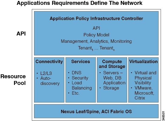
The APIC manages the scalable ACI multitenant fabric. The APIC provides a unified point of automation and management, policy programming, application deployment, and health monitoring for the fabric. The APIC, which is implemented as a replicated synchronized clustered controller, optimizes performance, supports any application anywhere, and provides unified operation of the physical and virtual infrastructure. The APIC enables network administrators to easily define the optimal network for applications. Data center operators can clearly see how applications consume network resources, easily isolate and troubleshoot application and infrastructure problems, andmonitor and profile resource usage patterns.
Cisco Application Centric Infrastructure Fabric Overview
The Cisco Application Centric Infrastructure Fabric (ACI) fabric includes Cisco Nexus 9000 Series switches with the APIC to run in the leaf/spine ACI fabric mode. These switches form a “fat-tree” network by connecting each leaf node to each spine node; all other devices connect to the leaf nodes. The APIC manages the ACI fabric. The recommended minimum configuration for the APIC is a cluster of three replicated hosts. The APIC fabric management functions do not operate in the data path of the fabric. The following figure shows an overview of the leaf/spin ACI fabric.
ACI Fabric Overview
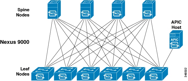
The ACI fabric provides consistent low-latency forwarding across high-bandwidth links (40 Gbps, with a 100-Gbps future capability). Traffic with the source and destination on the same leaf switch is handled locally, and all other traffic travels from the ingress leaf to the egress leaf through a spine switch. Although this architecture appears as two hops from a physical perspective, it is actually a single Layer 3 hop because the fabric operates as a single Layer 3 switch.
The ACI fabric object-oriented operating system (OS) runs on each Cisco Nexus 9000 Series node. It enables programming of objects for each configurable element of the system.
The ACI fabric OS renders policies from the APIC into a concrete model that runs in the physical infrastructure. The concrete model is analogous to compiled software; it is the form of the model that the switch operating system can execute. The figure below shows the relationship of the logical model to the concrete model and the switch OS.
Logical Model Rendered into a Concrete Model
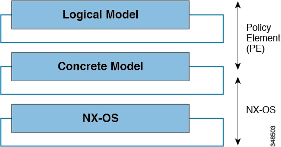
All the switch nodes contain a complete copy of the concrete model. When an administrator creates a policy in the APIC that represents a configuration, the APIC updates the logical model. The APIC then performs the intermediate step of creating a fully elaborated policy that it pushes into all the switch nodes where the concrete model is updated.
The APIC is responsible for fabric activation, switch firmware management, network policy configuration, and instantiation. While the APIC acts as the centralized policy and network management engine for the fabric, it is completely removed from the data path, including the forwarding topology. Therefore, the fabric can still forward traffic even when communication with the APIC is lost.
The Cisco Nexus 9000 Series switches offer modular and fixed 1-, 10-, and 40-Gigabit Ethernet switch configurations that operate in either Cisco NX-OS stand-alone mode for compatibility and consistency with the current Cisco Nexus switches or in ACI mode to take full advantage of the APIC's application policy-driven services and infrastructure automation features.
The ACI Policy Model Overview
The ACI policy model enables the specification of application requirements policies. The APIC automatically renders policies in the fabric infrastructure. When a user or process initiates an administrative change to an object in the fabric, the APIC first applies that change to the policy model. This policy model change then triggers a change to the actual managed endpoint. This approach is called a model-driven framework.
Policy Model Key Characteristics
Key characteristics of the policy model include the following:
-
As a model-driven architecture, the software maintains a complete representation of the administrative and operational state of the system (the model). The model applies uniformly to the fabric, services, system behaviors, and virtual and physical devices attached to the network.
-
The logical and concrete domains are separated; the logical configurations are rendered into concrete configurations by applying the policies in relation to the available physical resources. No configuration is carried out against concrete entities. Concrete entities are configured implicitly as a side effect of the changes to the APIC policy model. Concrete entities can be, but do not have to be, physical (such as a virtual machine or a VLAN).
-
The system prohibits communications with newly connected devices until the policy model is updated to include the new device.
-
Network administrators do not configure logical and physical system resources directly but rather define logical (hardware independent) configurations and APIC policies that control different aspects of the system behavior.
Managed object manipulation in the model relieves engineers from the task of administering isolated, individual component configurations. These characteristics enable automation and flexible workload provisioning that can locate any workload anywhere in the infrastructure. Network-attached services can be easily deployed, and the APIC provides an automation framework to manage the life cycle of those network-attached services.
Logical Constructs
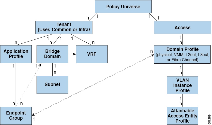
The policy model manages the entire fabric, including the infrastructure, authentication, security, services, applications, and diagnostics. Logical constructs in the policy model define how the fabric meets the needs of any of the functions of the fabric. The following figure provides an overview of the ACI policy model logical constructs.
ACI Policy Model Logical Constructs Overview
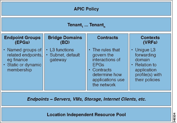
Fabric-wide or tenant administrators create predefined policies that contain application or shared resource requirements. These policies automate the provisioning of applications, network-attached services, security policies, and tenant subnets, which puts administrators in the position of approaching the resource pool in terms of applications rather than infrastructure building blocks. The application needs to drive the networking behavior, not the other way around.
Every aspect of ACI functionality is encompassed within the object model. Any configuration that can be made on the fabric, can be made programmatically using the REST API. Likewise, any monitoring, statistics, or fault information can be programmatically read from the APIC using the REST API.
ACI Utilities for Developers
Cisco ACI includes utilities that enable developers to effectively use the ACI REST APIs.
APIC API Inspector
The API Inspector is included in the APIC GUI. It provides a real-time display of REST API commands that the APIC processes to perform GUI interactions. The APIC user login drop-down menu includes the API Inspector option which opens the window shown in the figure below.
The API Inspector dynamically displays REST commands issued by the APIC. All operations that are performed in the GUI invoke REST calls to fetch and commit the information being accessed. The API Inspector further simplifies the process of examining what is taking place on the REST interface as the GUI is navigated by displaying in real time the URIs and payloads. When a new configuration is committed, the API Inspector displays the resulting POST requests, and when information is displayed on the GUI, the GET request is displayed.
After the API Inspector is brought up, time stamps will appear along with the REST method, URIs, and payloads. There may also be occasional updates in the list as the GUI refreshes subscriptions to data being shown on the screen.
Visore Managed Object Viewer
Visore is a read-only management information tree (MIT) browser as shown in the figure below. It enables distinguished name (DN) and class queries with optional filters.
Visore MO Viewer
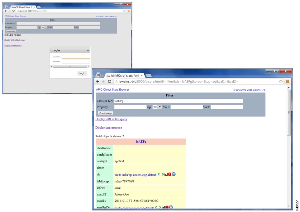
The Visore managed object viewer is provided with the APIC. It is at this location: http(s)://host[:port]/visore.html
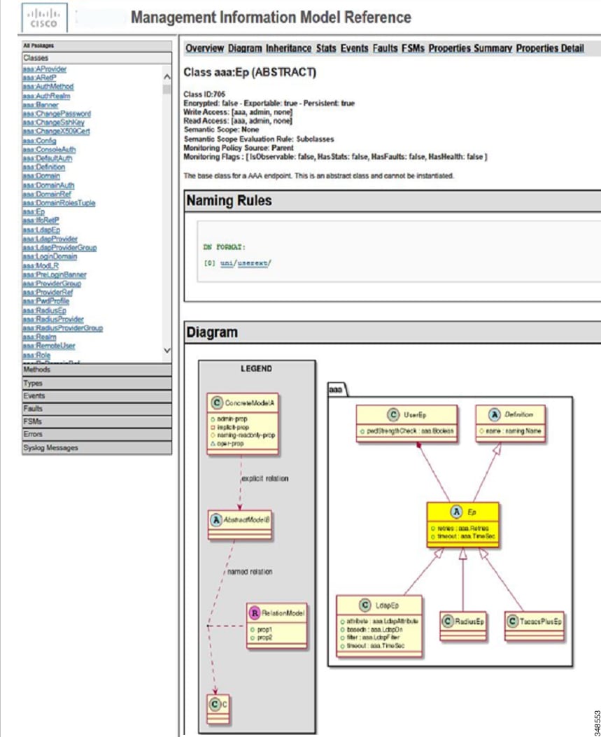
Management Information Model Reference
The Management Information Model (MIM) contains all of the managed objects in the system and their properties. For details, see the Cisco APIC Management Information Model Reference Guide.
The ACI object model is represented in the Management Information Tree (MIT) that is an object oriented data base. Every branch represents a functional area, and every node is a managed object - has a CLASS and a globally unique Distinguished Name formed by a parent name and the relative name.
Top levels of the policy model in the ACI Management Information Model Tree
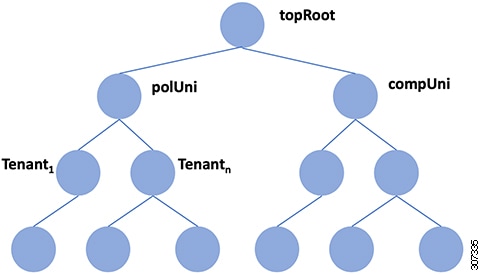
polUni is the top level class for all policy definition/resolution objects, and compUni is the top level class for all compute related objects.
The following figure provides an example of how an administrator can use the MIM to research an object in the MIT.
MIM Reference
About the REST API
The Application Policy Infrastructure Controller (APIC) Representational State Transfer (REST) API is a programmatic interface that uses the RESTful services architecture. The API accepts and returns HTTP (not enabled by default) or HTTPS messages that contain JavaScript Object Notation (JSON) or Extensible Markup Language (XML) documents. You can use any programming language to generate the messages and the JSON or XML documents that contain the API methods or Managed Object (MO) descriptions.
The REST API is the interface into the management information tree (MIT) and allows manipulation of the object model state. The same REST interface is used by the APIC CLI, GUI, and SDK, so that whenever information is displayed, it is read through the REST API, and when configuration changes are made, they are written through the REST API. The REST API also provides an interface through which other information can be retrieved, including statistics, faults, and audit events. It even provides a means of subscribing to push-based event notification, so that when a change occurs in the MIT, an event can be sent through a web socket.
POSTman (http://www.getpostman.com), is a popular utility that can be used to interact with the APIC REST interface, to both send and receive data which may represent configuration, actions, policy and operational state data.
Standard REST methods are supported in the ACI API, which include POST, GET, and DELETE operations through HTTP.
|
Method |
Action |
Behavior |
|---|---|---|
|
GET |
Read |
Nullipotent |
|
POST |
Create / Update |
Idempotent |
|
DELETE |
Delete |
Idempotent |
The POST and DELETE methods are idempotent, meaning that there is no additional effect if they are called more than once with the same input parameters. The GET method is nullipotent, meaning that it can be called zero or more times without making any changes (or that it is a read-only operation).
Payloads to and from the REST interface can be encapsulated through either XML or JSON encoding. In the case of XML, the encoding operation is simple: the element tag is the name of the package and class, and any properties of that object are specified as attributes of that element. Containment is defined by creating child elements.
For JSON, encoding requires definition of certain entities to reflect the tree-based hierarchy; however, the definition is repeated at all levels of the tree, so it is fairly simple to implement after it is initially understood.
-
All objects are described as JSON dictionaries, in which the key is the name of the package and class. The value is another nested dictionary with two keys: attribute and children.
-
The attribute key contains a further nested dictionary describing key-value pairs that define attributes on the object.
-
The children key contains a list that defines all the child objects. The children in this list are dictionaries containing any nested objects, which are defined as described here.
The REST API has both northbound and the southbound programmatic interfaces. The northbound REST API accepts configuration and access to management functions of the APIC. This interface provides access for automation tools, provisioning scripts and third party monitoring and management tools.
ACI Northbound and Southbound APIs
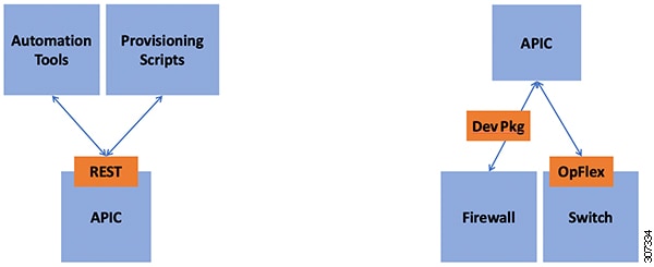
Southbound interfaces on the APIC allow for the declarative model of intent to be extended beyond the fabric, into subordinate devices. This is a key aspect to the openness of the ACI fabric, in that policy can be programmed once via the APIC and then pushed out to hypervisors, L4-7 devices and more, without the need to individually configure those devices. This southbound extension is realized through L4-7 Device Packages and the OpFlex protocol.
The L4-7 device package interface allows for ACI to apply policy to existing L4-7 devices that do not have an implicit knowledge of ACI policy. These devices can be from any vendor, so long as the device has some form of interface which is accessible via IP. The implementation of device packages is done via Python scripts that run on the APIC in a contained execution environment. The scripts can access the device through their native configuration interfaces, be they REST, CLI, SOAP or others. As a user makes changes to service graphs or EPG policy, the device package translates the APIC policy into API calls on the L4-7 device.
OpFlex is designed to allow the exchange of data for managed objects that are part of an informational model. The protocol supports XML and JSON, as well as the binary encoding used in some scenarios, and uses standard remote procedure call (RPC) mechanisms such as JSON-RPC over TCP. In ACI, OpFlex extends policy to the Application Virtual Switch as well as to Group Based Policy in OpenStack.
Read Operations
After the object payloads are properly encoded as XML or JSON, they can be used in create, read, update, or delete operations. The following diagram shows the syntax for an ACI REST API read operation.
REST Syntax
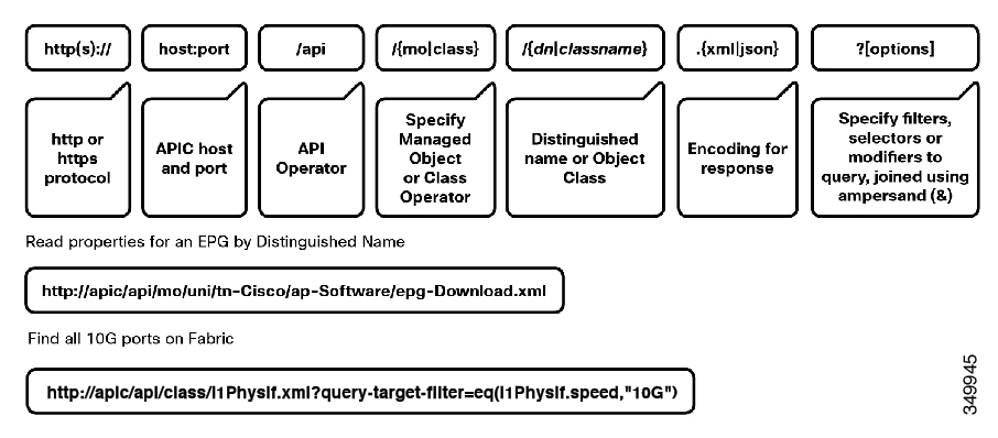
A universal resource identifier (URI) provides access a target resource. The first two sections of the request URI specify the protocol and access details of the APIC. The literal string /api, indicates that the API is to be invoked. The next specifies whether the operation is for an MO or a class. Next, either the fully qualified Dn for object-based queries, or the package and class name for class-based queries is specified. The final mandatory part of the request URI is the encoding format: either .xml or .json. This is the only method by which the payload format is defined (the APIC ignores Content-Type and other headers).
Write Operations
Create and update operations in the REST API are both implemented using the POST method. If an object does not already exist, it will be created, and if it does already exist, it will be updated to reflect any changes between its existing state and desired state.
REST Payload
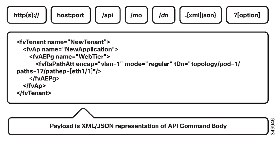
Both create and update operations can contain complex object hierarchies, so that a complete tree can be defined in a single command so long as all objects are within the same context root and are under the 1MB limit for data payloads for the REST API. This limit guarantees performance and protects the system when it is under high load.
Create and update operations use the same syntax as read operations, except that they are always targeted at an object level, because you cannot make changes to every object of a specific class (nor would you want to). The literal string /mo indicates that the Dn of the managed object is provided, followed by theactual Dn. Filter strings apply to POST operations. For example, to retrieve the results of a POST operation in the response, pass the rsp-subtree=modified query string to indicate that the response is to include any objects that have been modified by the POST operation.
The payload of the POST operation contains the XML or JSON encoded data representing the managed object that defines the Cisco API command body.
Filters
The REST API supports a wide range of flexible filters, useful for narrowing the scope of your search to allow information to be located more quickly. The filters themselves are appended as query URI options, starting with a question mark (?) and concatenated with an ampersand (&). Multiple conditions can be joined together to form complex filters.
Authentication
REST API username- and password-based authentication uses a special subset of request Universal Resource Identifiers (URIs), including aaaLogin, aaaLogout, and aaaRefresh as the DN targets of a POST operation. Their payloads contain a simple XML or JSON payload containing the MO representation of an aaaUser object with the attribute name and pwd defining the username and password: for example, <aaaUser name='admin' pwd='password'/>. The response to the POST operation will contain an authentication token as both a Set-Cookie header and an attribute to the aaaLogin object in the response named token, for which the XPath is /imdata/aaaLogin/@token if the encoding is XML. Subsequent operations on the REST API can use this token value as a cookie named APIC-cookie to authenticate future requests.
The following example authenticates a local APIC user to the APIC.
POST https://<host>/api/aaaLogin.json
{
  "aaaUser" : {
    "attributes" : {
      "name" : "admin",
      "pwd" : "Pa$$w0rd"
    }
  }
}
Subscription
The REST API supports the subscription to one or more MOs during your active API session. When any MO is created, changed, or deleted because of a user- or system-initiated action, an event is generated. If the event changes the data on any of the active subscribed queries, the APIC will send out a notification to the API client that created the subscription.
ACI Development Environment
The ACI object model represents network configuration with application-based semantics that can be consumed and posted against using the REST API. ACI provides a variety of access methods to read and manipulate this data.
Common ACI Development Libraries
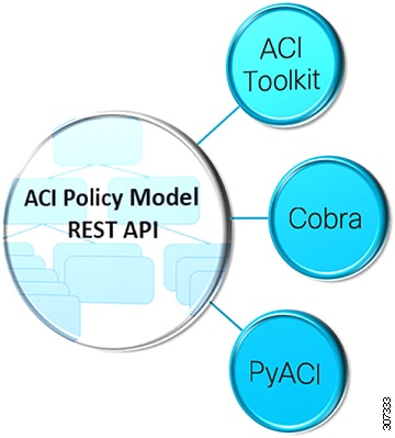
All 3 libraries are simply wrappers to access the Rest API. Largely a tradeoff between personal preference, need for completeness, comfort with the ACI object model, and requirement for formal support beyond an active community
APIC Toolkit
ACI Toolkit attempts to make life easier for the developer. Python libraries that allows you to quickly get the most common ACI workflows up and running. Can use Rest API directly along with ACI Toolkit, Cobra, and PyACI in the same script The complete Cisco Application Centric Infrastructure (ACI) object model contains many entities, which may be daunting for a user being first introduced to network programmability. The ACI Toolkit makes available a simplified subset of the model that can act as an introduction to the concepts in ACI, and give users a way to quickly bring up common tasks and workflows. Various applications that are now products or features of ACI have been built in the ACI Toolkit. Examples include Multi-Site, Endpoint Tracker, ACI Lint, ACI Configuration Snapshot and Rollback, and many more.
While the ACI Toolkit provides some useful tools for an operator to immediately use, the real value is in the ability to take these examples as a starting point, and modify or extend these samples to suit your particular needs.
Cobra
Cobra provides complete access to the object model but may be more difficult for beginning developers. The ACI engineering team uses Cobra. Much of the CLI on the ACI switches was developed with Cobra.
PyACI
PyACI provides alternative Python bindings for ACI REST API with the option to use XML or JSON payload. Facilitates authoring concise scripts Provides better logging.
APIC Sandbox Environment
DevNet Sandbox makes Cisco's free spread of technology available to developers and engineers by providing packaged labs we call Sandboxes. There are two types of sandboxes, Always-On and Reservation. Each sandbox typically highlights one Cisco product (for example, CallManager, APIC, etc). Sandboxes can be used for development, testing APIs, learning how to configure a product, training, hackathons, and more.
ARYA
The process of building a request can be time consuming, because you must represent the object data payload as Python code reflecting the object changes that you want to make. Because the Cobra SDK is directly modeled on the Cisco ACI object model, you should be able to generate code directly from what resides in the object model. You can do so with the Cisco APIC REST to Python Adapter, known as Arya.
Ansible
The Ansible ACI modules provide a user-friendly interface to managing your ACI environment using Ansible playbooks. For instance ensuring that a specific tenant exists, is done using the following Ansible task using module aci_tenant:
name: Ensure tenant customer-xyz exists
  aci_tenant:
    host: my-apic-1
    username: admin
    password: my-password

    tenant: customer-xyz
    description: Customer XYZ
    state: present
A complete list of existing ACI modules is available for the latest stable release on the list of network modules. You can also view the current development version. If you want to learn how to write your own ACI modules to contribute, look at the Developing Cisco ACI modules section.
OpenStack
OpenStack is an open source infrastructure as a service (IaaS) initiative for creating and managing large groups of virtual private servers in a data center. Cisco OpenStack plugins enable OpenStack instances to leverage the ACI fabric as a software defined networking (SDN) platform. This enables dynamic creation of networking constructs that are driven directly from OpenStack, while providing additional visibility and control through the ACI APIC controller. OpenStack supports interoperability between cloud services and allows businesses to build AWS-like cloud services in their own data centers.
Puppet
Puppet is a configuration management tool from Puppet Labs, Inc. Although Puppet was originally designed for large scale server management, many datacenter operators would like to consolidate server and network device provisioning using the same tool.
Cisco Puppet Module
An APIC controller does not run an embedded Puppet agent. Instead, Cisco provides a Puppet module ("ciscoacipuppet"), which uses a Cisco ACI-specific Puppet device to relay configuration management requests to the APIC controller. The ciscoacipuppet module interprets change information in the received Puppet manifest and translates the change requests into APIC REST API messages to implement configuration changes in the ACI fabric.
For details on the installation, setup, and usage of the ciscoacipuppet module, refer to the documentation on GitHub and Puppet Forge at the following URLs:
Only a subset of APIC managed objects can be provisioned using the ciscoacipuppet Puppet module. To understand the level of support and the limitations, refer to the ciscoacipuppet module documentation on GitHub and Puppet Forge.
GitHub
GitHub provides both free and paid hosting services that allow individuals to collaborate with millions of other GitHub users. GitHub also provides techniques for tracking issues, securing access to projects, and built-in project documentation. The combination of all of these features makes GitHub a very common place for members of the community to share code with one another, build on each other's work, and contribute their efforts back into larger projects.
Locating Policy Model Objects
The Cisco ACI uses an information-model-based architecture (management information tree [MIT]) in which the model describes all the information that can be controlled by a management process. Object instances are referred to as managed objects (MOs).
The following figure shows the distinguished name, which uniquely represents any given MO instance, and the relative name, which represents the MO locally underneath its parent MO. All objects in the MIT exist under the root object.
MO Distinguished and Relative Names
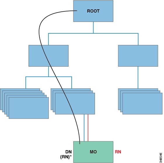
Every MO in the system can be identified by a unique distinguished name (DN). This approach allows the object to be referred to globally. In addition to its distinguished name, each object can be referred to by its relative name (RN). The relative name identifies an object relative to its parent object. Any given object's distinguished name is derived from its own relative name that is appended to its parent object's distinguished name.
The distinguished name enables you to unambiguously a specific target object. The relative name identifies an object from its siblings within the context of its parent object. The distinguished name contains a sequence of relative names.
dn = {rn}/{rn}/{rn}/{rn}
dn =”sys/ch/lcslot-1/lc/leafport-1”
Distinguished names are directly mapped to URLs. Either the relative name or the distinguished name can be used to access an object, depending on the current location in the MIT.
Because of the hierarchical nature of the tree and the attribute system used to identify object classes, the tree can be queried in several ways for obtaining managed object information. Queries can be performed on an object itself through its distinguished name, on a class of objects such as a switch chassis, or on a tree-level to discover all members of an object.
Examples of query types are below:
-
To get a MO and everything under it: rsp-subtree=full
-
To get just the configurable items: rsp-prop-include=config-only
-
To get just particular class from a MO: target-subtree-class=
-
To get just particular class: filter class = vzFilter
-
To get just particular entry: filter class = vzEntry
-
To get just contracts: filter class = vzBrCP
For all MIT queries, an administrator can optionally return the entire subtree or a partial subtree. Additionally, the role-based access control (RBAC) mechanism in the system dictates which objects are returned; only the objects that the user has rights to view will ever be returned.
Tree-Level Queries
The following figure shows two chassis that are queried at the tree level.
Tree-Level Queries
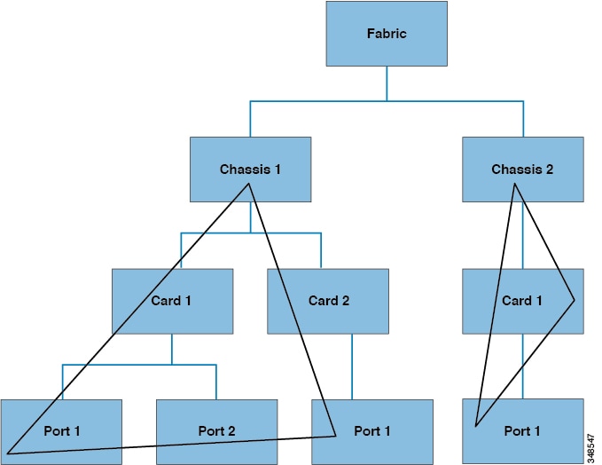
Both queries return the referenced object and its child objects. This approach is useful for discovering the components of a larger system. In this example, the query discovers the cards and ports of a given switch chassis.
Class-Level Queries
The following figure shows the second query type: the class-level query.
Class-Level Queries
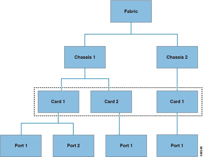
Class-level queries return all the objects of a given class. This approach is useful for discovering all the objects of a certain type that are available in the MIT. In this example, the class used is Cards, which returns all the objects of type Cards.
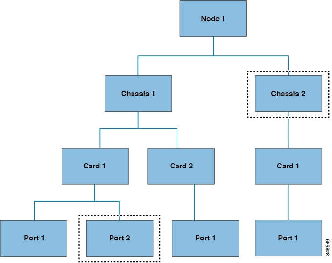
Object-Level Queries
The third query type is an object-level query. In an object-level query a distinguished name is used to return a specific object. The figure below shows two object-level queries: for Node 1 in Chassis 2, and one for Node 1 in Chassis 1 in Card 1 in Port 2.
Object-Level Queries
Managed Object Properties
Managed objects contain properties that define the managed object. Properties in a managed object are divided into chunks that are managed by processes in the operating system. Any object can have several processes that access it. All these properties together are compiled at runtime and are presented to the user as a single object. The following figure shows an example of this relationship.
Managed Object Properties
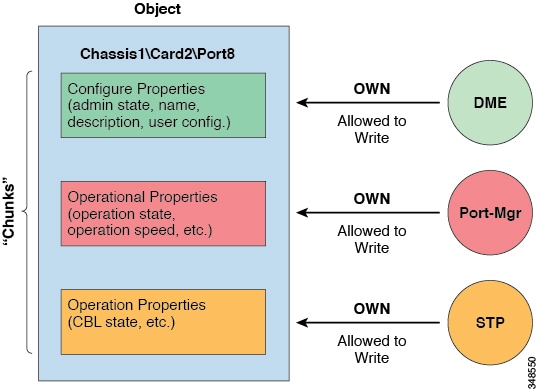
The example object has three processes that write to property chunks that are in the object. The data management engine (DME), which is the interface between the Cisco APIC (the user) and the object, the port manager, which handles port configuration, and the spanning tree protocol (STP) all interact with chunks of this object. The APIC presents the object to the user as a single entity compiled at runtime.
Accessing the Object Data Through REST Interfaces
REST is a software architecture style for distributed systems such as the World Wide Web. REST has increasingly displaced other design models such as Simple Object Access Protocol (SOAP) and Web Services Description Language (WSDL) due to its simpler style. The Cisco APIC supports REST interfaces for programmatic access to the entire Cisco ACI solution.
The object-based information model of Cisco ACI makes it a very good fit for REST interfaces: URLs and URIs map directly to distinguished names that identify objects on the MIT, and any data on the MIT can be described as a self-contained structured text tree document that is encoded in XML or JSON. The objects have parent-child relationships that are identified using distinguished names and properties, which are read and modified by a set of create, read, update, and delete (CRUD) operations.
Objects can be accessed at their well-defined address, their REST URLs, using standard HTTP commands for retrieval and manipulation of Cisco APIC object data. The URL format used can be represented as follows:
<system>/api/[mo|class]/[dn|class][:method].[xml|json]?{options}
The various building blocks of the preceding URL are as follows:
-
system: System identifier; an IP address or DNS-resolvable hostname
-
mo | class: Indication of whether this is a MO in the MIT, or class-level query
-
class: MO class (as specified in the information model) of the objects queried; the class name is represented as <pkgName><ManagedObjectClassName>
-
dn: Distinguished name (unique hierarchical name of the object in the MIT) of the object queried
-
method: Optional indication of the method being invoked on the object; applies only to HTTP POST requests
-
xml | json: Encoding format
-
options: Query options, filters, and arguments
With the capability to address and access an individual object or a class of objects with the REST URL, one can achieve complete programmatic access to the entire object tree and to the entire system.
The following are examples of REST queries:
-
Find all EPGs and their faults under tenant solar.
http://192.168.10.1:7580/api/mo/uni/tn-solar.xml?query-target=subtree&target-subtree-class=fvAEPg&rsp-subtree-include=faults
-
Filtered EPG query
http://192.168.10.1:7580/api/class/fvAEPg.xml?query-target-filter=eq(fvAEPg.fabEncap,%20"vxlan-12780288")
The Cisco ACI Policy Management Information Model
The fabric comprises the physical and logical components as recorded in the Management Information Model (MIM), which can be represented in a hierarchical management information tree (MIT). The information model is stored and managed by processes that run on the APIC. Similar to the OSI Common Management Information Protocol (CMIP) and other X.500 variants, the APIC enables the control of managed resources by presenting their manageable characteristics as object properties that can be inherited according to the location of the object within the hierarchical structure of the MIT.
Each node in the tree represents a managed object (MO) or group of objects. MOs are abstractions of fabric resources. An MO can represent a concrete object, such as a switch, adapter, or a logical object, such as an application profile, endpoint group, or fault. The following figure provides an overview of the MIT.
Cisco ACI Management Information Model Policy Universe Overview
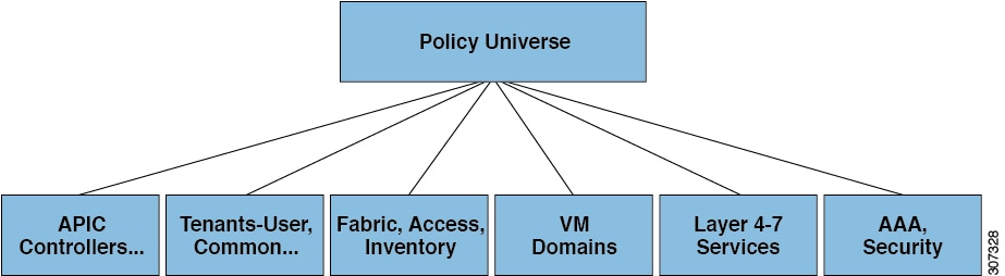
The hierarchical structure starts with the policy universe under the top (Root) and contains parent and child nodes. Each node in the tree is an MO and each object in the fabric has a unique distinguished name (DN) that describes the object and locates its place in the tree. The following managed objects contain the policies that govern the operation of the system:
-
APIC controllers comprise a replicated synchronized clustered controller that provides management, policy programming, application deployment, and health monitoring for the multitenant fabric.
-
A tenant is a container for policies that enable an administrator to exercise domain-based access control. The system provides the following four kinds of tenants:
-
User tenants contain policies that govern the operation of resources such as applications, databases, web servers, network-attached storage, virtual machines, and so on.
-
The common tenant is provided by the system but can be configured by the fabric administrator. It contains policies that govern the operation of resources accessible to all tenants, such as firewalls, load balancers, Layer 4 to Layer 7 services, intrusion detection appliances, and so on.
-
The infrastructure tenant is provided by the system but can be configured by the fabric administrator. It contains policies that govern the operation of infrastructure resources such as the fabric VXLAN overlay. It also enables a fabric provider to selectively deploy resources to one or more user tenants. Infrastructure tenant polices are configurable by the fabric administrator.
-
The management tenant is provided by the system but can be configured by the fabric administrator. It contains policies that govern the operation of fabric management functions used for in-band and out-of-band configuration of fabric nodes. The management tenant contains a private out-of-bound address space for the APIC/fabric internal communications that is outside the fabric data path that provides access through the management port of the switches. The management tenant enables discovery and automation of communications with virtual machine controllers.
-
-
Access policies govern the operation of switch access ports that provide connectivity to resources such as storage, compute, Layer 2 and Layer 3 (bridged and routed) connectivity, virtual machine hypervisors, Layer 4 to Layer 7 devices, and so on. If a tenant requires interface configurations other than those provided in the default link, Cisco Discovery Protocol (CDP), Link Layer Discovery Protocol (LLDP), Link Aggregation Control Protocol (LACP), or Spanning Tree, an administrator must configure access policies to enable such configurations on the access ports of the leaf switches.
-
Fabric policies govern the operation of the switch fabric ports, including such functions as Network Time Protocol (NTP) server synchronization, Intermediate System-to-Intermediate System Protocol (IS-IS), Border Gateway Protocol (BGP) route reflectors, Domain Name System (DNS) and so on. The fabric MO contains objects such as power supplies, fans, chassis, and so on.
-
Virtual Machine (VM) domains group VM controllers with similar networking policy requirements. VM controllers can share VLAN or Virtual Extensible Local Area Network (VXLAN) space and application endpoint groups (EPGs). The APIC communicates with the VM controller to publish network configurations such as port groups that are then applied to the virtual workloads.
-
Layer 4 to Layer 7 service integration life cycle automation framework enables the system to dynamically respond when a service comes online or goes offline. Policies provide service device package and inventory management functions.
-
Access, authentication, and accounting (AAA) policies govern user privileges, roles, and security domains of the Cisco ACI fabric.
Tenants
A tenant (fvTenant) is a logical container for application policies that enable an administrator to exercise domain-based access control. A
tenant represents a unit of isolation from a policy perspective, but it does not represent a private network. Tenants can
represent a customer in a service provider setting, an organization or domain in an enterprise setting, or just a convenient
grouping of policies. The following figure provides an overview of the tenant portion of the management information tree (MIT).
Tenants
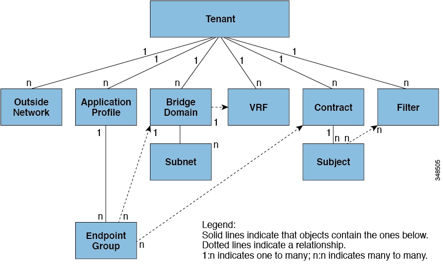
Tenants can be isolated from one another or can share resources. The primary elements that the tenant contains are filters, contracts, outside networks, bridge domains, Virtual Routing and Forwarding (VRF) instances, and application profiles that contain endpoint groups (EPGs). Entities in the tenant inherit its policies. VRFs are also known as contexts; each VRF can be associated with multiple bridge domains.
Tenants are logical containers for application policies. The fabric can contain multiple tenants. You must configure a tenant before you can deploy any Layer 4 to Layer 7 services. The ACI fabric supports IPv4, IPv6, and dual-stack configurations for tenant networking.
Endpoint Groups
An EPG is a managed object that is a named logical entity that contains a collection of endpoints. Endpoints are devices that are connected to the network directly or indirectly. They have an address (identity), a location, attributes (such as version or patch level), and can be physical or virtual. Knowing the address of an endpoint also enables access to all its other identity details. EPGs are fully decoupled from the physical and logical topology. Endpoint examples include servers, virtual machines, network-attached storage, or clients on the Internet. Endpoint membership in an EPG can be dynamic or static.
The ACI fabric can contain the following types of EPGs:
-
Application endpoint group (
fvAEPg) -
Layer 2 external outside network instance endpoint group (
l2extInstP) -
Layer 3 external outside network instance endpoint group (
l3extInstP) -
Management endpoint groups for out-of-band (
mgmtOoB) or in-band (mgmtInB) access.
EPGs contain endpoints that have common policy requirements such as security, virtual machine mobility (VMM), QoS, or Layer 4 to Layer 7 services. Rather than configure and manage endpoints individually, they are placed in an EPG and are managed as a group.
Policies apply to EPGs, never to individual endpoints. An EPG can be statically configured by an administrator in the APIC, or dynamically configured by an automated system such as vCenter or OpenStack.
Regardless of how an EPG is configured, EPG policies are applied to the endpoints they contain.
WAN router connectivity to the fabric is an example of a configuration that uses a static EPG. To configure WAN router connectivity
to the fabric, an administrator configures an l3extInstP EPG that includes any endpoints within an associated WAN subnet. The fabric learns of the EPG endpoints through a discovery
process as the endpoints progress through their connectivity life cycle. Upon learning of the endpoint, the fabric applies
thel3extInstP EPG policies accordingly. For example, when a WAN connected client initiates a TCP session with a server within an application
(fvAEPg) EPG, the l3extInstP EPG applies its policies to that client endpoint before the communication with the fvAEPg EPG web server begins. When the client server TCP session ends and communication between the client and server terminate,
that endpoint no longer exists in the fabric.
Virtual machine management connectivity to VMware vCenter is an example of a configuration that uses a dynamic EPG. Once the virtual machine management domain is configured in the fabric, vCenter triggers the dynamic configuration of EPGs that enable virtual machine endpoints to start up, move, and shut down as needed.
Bridge Domains and Subnets
A bridge domain (fvBD) represents a Layer 2 forwarding construct within the fabric. The following figure shows the location of bridge domains (BDs)
in the management information tree (MIT) and their relation to other objects in the tenant.
A BD must be linked to a VRF (also known as a context or private network). It must have at least one subnet (fvSubnet) associated with it. The BD defines the unique Layer 2 MAC address space and a Layer 2 flood domain if such flooding is enabled.
While a VRF defines a unique IP address space, that address space can consist of multiple subnets. Those subnets are defined
in one or more BDs that reference the corresponding VRF.
The options for a subnet under a BD or under an EPG are as follows:
-
Public—the subnet can be exported to a routed connection.
-
Private—the subnet applies only within its tenant.
-
Shared—the subnetcan be shared with and exported to multiple VRFs in the same tenant or across tenants as part of a shared service. An example of a shared service is a routed connection to an EPG present in another VRF in a different tenant. This enables traffic to pass in both directions across VRFs. An EPG that provides a shared service must have its subnet configured under that EPG (not under a BD), and its scope must be set to advertised externally, and shared between VRFs.
Labels, Filters, Aliases, and Subjects Govern EPG Communications
Label, subject, alias and filter managed-objects enable mixing and matching among EPGs and contracts so as to satisfy various applications or service delivery requirements. The following figure shows the location of application subjects and filters in the management information tree (MIT) and their relation to other objects in the tenant.
Contracts can contain multiple communication rules and multiple EPGs can both consume and provide multiple contracts. Labels control which rules apply when communicating between a specific pair of EPGs. A policy designer can compactly represent complex communication policies and re-use these policies across multiple instances of an application. For example, the sample policy in the Cisco Application Centric Infrastructure Fundamentals "Contract Scope Examples" chapter shows how the same contract uses labels, subjects, and filters to differentiate how communications occur among different EPGs that require HTTP or HTTPS.
Labels, subjects, aliases and filters define EPG communications according to the following options:
-
Labels are managed objects with only one property: a name. Labels enable classifying which objects can and cannot communicate with one another. Label matching is done first. If the labels do not match, no other contract or filter information is processed. The label match attribute can be one of these values: at least one (the default), all, none, or exactly one. The Cisco Application Centric Infrastructure Fundamentals "Label Matching" chapter shows simple examples of all the label match types and their results.

Note
Labels can be applied to a variety of provider and consumer managed objects, including EPGs, contracts, bridge domains, DHCP relay policies, and DNS policies. Labels do not apply across object types; a label on an application EPG has no relevance to a label on a bridge domain.
-
Labels determine which EPG consumers and EPG providers can communicate with one another. Label matching determines which subjects of a contract are used with a given EPG provider or EPG consumer of that contract.
-
The two types of labels are as follows:
-
Subject labels that are applied to EPGs. Subject label matching enables EPGs to choose a subset of the subjects in a contract.
-
Provider/consumer labels that are applied to EPGs. Provider/consumer label matching enables consumer EPGs to choose their provider EPGs and vice versa.
-
-
Aliases are alternative names you can apply to objects, which can be changed, unlike the name.
-
Filters are Layer 2 to Layer 4 fields, TCP/IP header fields such as Layer 3 protocol type, Layer 4 ports, and so forth. According to its related contract, an EPG provider dictates the protocols and ports in both the in and out directions. Contract subjects contain associations to the filters (and their directions) that are applied between EPGs that produce and consume the contract.
-
Subjects are contained in contracts. One or more subjects within a contract use filters to specify the type of traffic that can be communicated and how it occurs. For example, for HTTPS messages, the subject specifies the direction and the filters that specify the IP address type (for example, IPv4), the HTTP protocol, and the ports allowed. Subjects determine if filters are unidirectional or bidirectional. A unidirectional filter is used in one direction. Unidirectional filters define in or out communications but not the same for both. Bidirectional filters are the same for both; they define both in and out communications.
VXLAN in ACI
VXLAN is an industry-standard protocol that extends Layer 2 segments over Layer 3 infrastructure to build Layer 2 overlay logical networks. The ACI infrastructure Layer 2 domains reside in the overlay, with isolated broadcast and failure bridge domains. This approach allows the data center network to grow without risking creation of too large a failure domain.
All traffic in the ACI fabric is normalized as VXLAN packets. At ingress, ACI encapsulates external VLAN/VXLAN/NVGRE packets in a VXLAN packet. The following figure illustrates ACI encapsulation normalization.
ACI Encapsulation Normalization
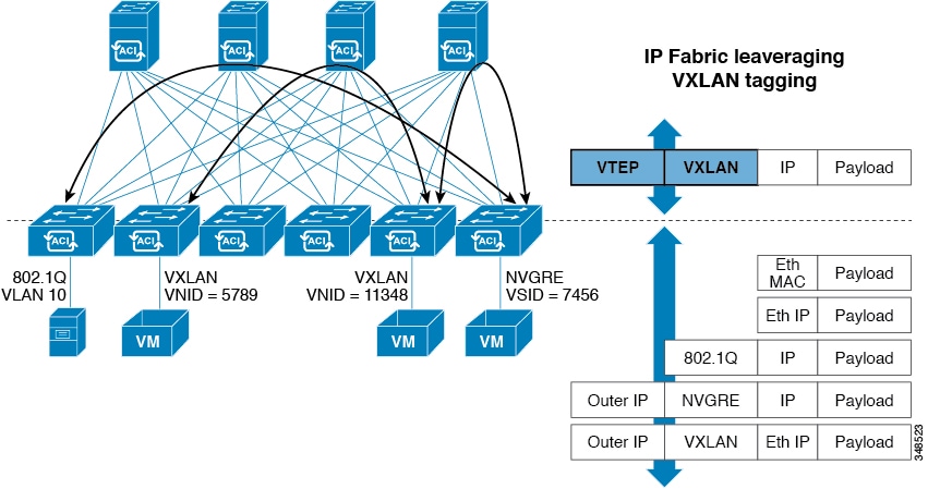
Forwarding in the ACI fabric is not limited to or constrained by the encapsulation type or encapsulation overlay network. An ACI bridge domain forwarding policy can be defined to provide standard VLAN behavior where required.
Because every packet in the fabric carries ACI policy attributes, ACI can consistently enforce policy in a fully distributed manner. ACI decouples application policy EPG identity from forwarding. The following figure illustrates how the ACI VXLAN header identifies application policy within the fabric.
ACI VXLAN Packet Format
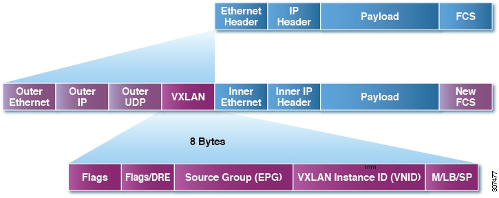
The ACI VXLAN packet contains both Layer 2 MAC address and Layer 3 IP address source and destination fields, which enables highly efficient and scalable forwarding within the fabric. The ACI VXLAN packed header source group field identifies the application policy endpoint group (EPG) to which the packet belongs. The VXLAN Instance ID (VNID) enables forwarding of the packet through tenant virtual routing and forwarding (VRF) domains within the fabric. The 24-bit VNID field in the VXLAN header provides an expanded address space for up to 16 million unique Layer 2 segments in the same network. This expanded address space gives IT departments and cloud providers greater flexibility as they build large multitenant data centers.
VXLAN enables ACI to deploy Layer 2 virtual networks at scale across the fabric underlay Layer 3 infrastructure. Application endpoint hosts can be flexibly placed in the data center network without concern for the Layer 3 boundary of the underlay infrastructure, while maintaining Layer 2 adjacency in a VXLAN overlay network.
In the leaf switches, policy configuration translates into zoning-rules. Each zoning-rule has a rule id, a primary key that is composed of scope (VRF VNID), srcEPG, dstEPG, and scope filterId. Actions can be permit, deny, redir, copy, or log. There is also a rule priority.
Zoning-rules are programmed in leaf switch policy TCAM (ternary content-addressable memory) hardware entries. TCAM is a specialized type of high-speed memory that searches its entire contents in a single clock cycle. The priority of each TCAM entry is based on the rule priority, filter priority, and if no-stats is set (compression is enabled or not).
|
8 bits |
1 bit |
1 bit |
6 bits |
|
Rule priority |
Low Priority (if set) |
No-stats (if set) |
Entry priority |
When the priority is the same, a rule with a deny action has a higher priority than a permit action.
When a VRF is in unenforced mode, there is an any-any permit rule that allows all traffic in the VRF scope by default.
When a VRF is in enforced mode, there is an any-any deny rule that disallows traffic by default. Contracts between EPGs must be configured to allow traffic that matches the specified filters.
By default, intra-EPG traffic is permitted but microsegmentation can be configured.
Contracts
In addition to EPGs, contracts (vzBrCP) are key objects in the policy model. EPGs can only communicate with other EPGs according to contract rules. The following
figure shows the location of contracts in the management information tree and their relation to other objects in the tenant.
An administrator uses a contract to select the type(s) of traffic that can pass between EPGs, including the protocols and ports allowed. If there is no contract, inter-EPG communication is disabled by default. There is no contract required for intra-EPG communication; intra-EPG communication is always implicitly allowed.
You can also configure contract preferred groups that enable greater control of communication between EPGs in a VRF. If most of the EPGs in the VRF should have open communication, but a few should only have limited communication with the other EPGs, you can configure a combination of a contract preferred group and contracts with filters to control communication precisely.
Contracts govern the following types of endpoint group communications:
-
Between ACI fabric application EPGs (
fvAEPg), both intra-tenant and inter-tenant -
Between ACI fabric application EPGs and Layer 2 external outside network instance EPGs (
l2extInstP) -
Between ACI fabric application EPGs and Layer 3 external outside network instance EPGs (
l3extInstP) - Between ACI fabric out-of-band (
mgmtOoB) or in-band (mgmtInB) management EPGs
Contracts govern the communication between EPGs that are labeled providers, consumers, or both. EPG providers expose contracts with which a would-be consumer EPG must comply. The relationship between an EPG and a contract can be either a provider or consumer. When an EPG provides a contract, communication with that EPG can be initiated from other EPGs as long as the communication complies with the provided contract. When an EPG consumes a contract, the endpoints in the consuming EPG may initiate communication with any endpoint in an EPG that is providing that contract. An EPG can both provide and consume the same contract. An EPG can also provide and consume multiple contracts simultaneously.
Inheritance
To streamline associating contracts to new EPGs, you can enable an EPG to inherit all the (provided and consumed) contracts associated directly to another EPG in the same tenant. Contract inheritance can be configured for application, microsegmented, L2Out, and L3Out EPGs.
You can also configure contract inheritance for Inter-EPG contracts, both provided and consumed. You can enable an EPG to inherit all the contracts associated directly to another EPG.
Preferred Groups
There are two types of policy enforcements available for EPGs in a VRF with a contract preferred group configured:
-
Included EPGs: EPGs can freely communicate with each other without contracts, if they have membership in a contract preferred group. This is based on the source-any-destination-any-permit default rule.
-
Excluded EPGs: EPGs that are not members of preferred groups require contracts to communicate with each other. Otherwise, the default source-any-destination-any-deny rule applies.
The contract preferred group feature enables greater control of communication between EPGs in a VRF. If most of the EPGs in the VRF should have open communication, but a few should have limited communication with the other EPGs, you can configure a combination of a contract preferred group and contracts with filters to control inter-EPG communication precisely.
Optimize Contract Performance
You can configure bidirectional contracts that support more efficient hardware TCAM storage of contract data. With optimization enabled, contract statistics for both directions are aggregated.
TCAM Optimization is supported on the Cisco Nexus 9000 Series top of rack (TOR) switches with names ending with EX and FX, and later (for example, N9K-C93180LC-EX or N9K-C93180YC-FX).
To configure efficient TCAM contract data storage, you enable the following options:
-
Mark the contracts to be applied in both directions between the provider and consumer
-
For filters with IP TCP or UDP protocols, enable the reverse port option
-
When configuring the contract subjects, enable the no stats directive.
About Copy Services
Unlike SPAN that duplicates all of the traffic, the Cisco Application Centric Infrastructure (ACI) copy services feature enables selectively copying portions of the traffic between endpoint groups, according to the specifications of the contract. Broadcast, unknown unicast and multicast (BUM), and control plane traffic that are not covered by the contract are not copied. In contrast, SPAN copies everything out of endpoint groups, access ports or uplink ports. Unlike SPAN, copy services do not add headers to the copied traffic. Copy service traffic is managed internally in the switch to minimize impact on normal traffic forwarding.
A copy service is configured as part of a Layer 4 to Layer 7 service graph template that specifies a copy cluster as the destination for the copied traffic. A copy service can tap into different hops within a service graph. For example, a copy service could select traffic between a consumer endpoint group and a firewall provider endpoint group, or between a server load balancer and a firewall. Copy clusters can be shared across tenants.
Copy services require you to do the following tasks:
-
Identify the source and destination endpoint groups.
-
Configure the contract that specifies what to copy according to the subject and what is allowed in the contract filter.
-
Configure Layer 4 to Layer 7 copy devices that identify the target devices and specify the ports where they attach.
-
Use the copy service as part of a Layer 4 to Layer 7 service graph template.
-
Configure a device selection policy that specifies which device will receive the traffic from the service graph. When you configure the device selection policy, you specify the contract, service graph, copy cluster, and cluster logical interface that is in copy device.
vzAny
The vzAny managed object provides a convenient way of associating all endpoint groups (EPGs) in a Virtual Routing and Forwarding (VRF)
instance to one or more contracts (vzBrCP), instead of creating a separate contract relation for each EPG.
In the Cisco ACI fabric, EPGs can only communicate with other EPGs according to contract rules. A relationship between an
EPG and a contract specifies whether the EPG provides the communications defined by the contract rules, consumes them, or
both. By dynamically applying contract rules to all EPGs in a VRF, vzAny automates the process of configuring EPG contract
relationships. Whenever a new EPG is added to a VRF, vzAny contract rules automatically apply. The vzAny one-to-all EPG relationship is the most efficient way of applying contract rules to all EPGs in a VRF.
Taboos
While the normal processes for ensuring security still apply, the ACI policy model aids in assuring the integrity of whatever security practices are employed. In the ACI policy model approach, all communications must conform to these conditions:
-
Communication is allowed only based on contracts, which are managed objects in the model. If there is no contract, inter-EPG communication is disabled by default.
-
No direct access to the hardware; all interaction is managed through the policy model.
Taboo contracts can be used to deny specific traffic that is otherwise allowed by contracts. The traffic to be dropped matches a pattern (such as, any EPG, a specific EPG, or traffic matching a filter). Taboo rules are unidirectional, denying any matching traffic coming toward an EPG that provides the contract.
With Cisco APIC Release 3.2(x) and switches with names that end in EX or FX, you can alternatively use a subject Deny action or Contract or Subject Exception in a standard contract to block traffic with specified patterns.
Attachable Entity Profiles Automate Assigning VLANs to EPGs
While tenant network policies are configured separately from fabric access policies, tenant policies are not activated unless their underlying access policies are in place. Fabric access external-facing interfaces connect to external devices such as virtual machine controllers and hypervisors, hosts, routers, or Fabric Extenders (FEXs). Access policies enable an administrator to configure port channels and virtual port channels, protocols such as LLDP, CDP, or LACP, and features such as monitoring or diagnostics.
Association of Endpoint Groups with Access Policies
In the policy model, EPGs are tightly coupled with VLANs. For traffic to flow, an EPG must be deployed on a leaf port with a VLAN in a physical, VMM, L2out, L3out, or Fiber Channel domain.
In the policy model, the domain profile associated to the EPG contains the VLAN instance profile. The domain profile contains both the VLAN instance profile (VLAN pool) and the attachable Access Entity Profile (AEP), which are associated directly with application EPGs. The AEP deploys the associated application EPGs to all the ports to which it is attached, and automates the task of assigning VLANs. While a large data center could easily have thousands of active virtual machines provisioned on hundreds of VLANs, the ACI fabric can automatically assign VLAN IDs from VLAN pools. This saves a tremendous amount of time, compared with trunking down VLANs in a traditional data center.
The ACI fabric provides multiple attachment points that connect through leaf ports to various external entities such as bare metal servers, virtual machine hypervisors, Layer 2 switches (for example, the Cisco UCS fabric interconnect), or Layer 3 routers (for example Cisco Nexus 7000 Series switches). These attachment points can be physical ports, FEX ports, port channels, or a virtual port channel (vPC) on leaf switches.
An Attachable Entity Profile (AEP) represents a group of external entities with similar infrastructure policy requirements. The infrastructure policies consist of physical interface policies that configure various protocol options, such as Cisco Discovery Protocol (CDP), Link Layer Discovery Protocol (LLDP), or Link Aggregation Control Protocol (LACP).
An AEP is required to deploy VLAN pools on leaf switches. Encapsulation blocks (and associated VLANs) are reusable across leaf switches. An AEP implicitly provides the scope of the VLAN pool to the physical infrastructure.
A virtual machine manager (VMM) domain automatically derives physical interface policies from the interface policy groups of an AEP.
An override policy at the AEP can be used to specify a different physical interface policy for a VMM domain. This policy is useful in scenarios where a VM controller is connected to the leaf switch through an intermediate Layer 2 node, and a different policy is desired at the leaf switch and VM controller physical ports. For example, you can configure LACP between a leaf switch and a Layer 2 node. At the same time, you can disable LACP between the VM controller and the Layer 2 switch by disabling LACP under the AEP override policy.
Microsegmentation
Microsegmentation associates endpoints from multiple EPGs into a microsegmented EPG according to virtual machine attributes, IP address, or MAC address. Virtual machine attributes include: VNic domain name, VM identifier, VM name, hypervisor identifier, VMM domain, datacenter, operating system, or custom attribute.
For any EPG, the ACI fabric ingress leaf switch classifies packets into an EPG according to the policies associated with the ingress port. Microsegmented EPGs apply policies to individual virtual or physical endpoints that are derived based on the VM attribute, MAC address, or IP address specified in the microsegmented EPG policy.
Intra-EPG Endpoint Isolation
Intra-EPG endpoint isolation policies provide full isolation for virtual or physical endpoints; no communication is allowed between endpoints in an EPG that is operating with isolation enforced. Isolation enforced EPGs reduce the number of EPG encapsulations required when many clients access a common service but are not allowed to communicate with each other.
An EPG is isolation enforced for all ACI network domains or none. While the ACI fabric implements isolation directly to connected endpoints, switches connected to the fabric are made aware of isolation rules according to a primary VLAN (PVLAN) tag.
Outside Networks
Outside network policies control connectivity to the outside. A tenant can contain multiple outside network objects. The following figure shows the location of outside networks in the management information tree (MIT) and their relation to other objects in the tenant.
Outside network policies specify the relevant Layer 2 (l2extOut) or Layer 3 (l3extOut) properties that control communications between an outside public or private network and the ACI fabric. External devices,
such as routers that connect to the WAN and enterprise core, or existing Layer 2 switches, connect to the front panel interface
of a leaf switch. The leaf switch that provides such connectivity is known as a border leaf. The border leaf switch interface
that connects to an external device can be configured as either a bridged or routed interface. In the case of a routed interface,
static or dynamic routing can be used. The border leaf switch can also perform all the functions of a normal leaf switch.
Tenant Policy Example XML Code
The table below lists commonly used ACI policy model object and class prefixes and property IDs:
|
Common Name |
Prefix-Property |
Module |
Class |
Parent Class |
Example |
|---|---|---|---|---|---|
| Tenant | tn-name | fv | Tenant | Uni | tn-Cisco |
| Context/VRF | ctx-name | fv | Ctx | Tenant | ctx-CiscoVRF |
| Bridge Domain | BD-name | fv | BD | Tenant | BD-Cisco |
| Subnet | subnet-ip | fv | Subnet | BD | subnet-10.1.2.1/24 |
| App Profile | ap-name | fv | Ap | Tenant | ap-IT-test |
| EPG | epg-name | fv | AEPg | Ap | epg-Database |
| Client Endpoint | cep-name | fv | CEp | AEPg | cep-0000.1111.2222 |
| IP Address | ip-addr | fv | Ip | CEp | ip-10.1.2.20 |
| L3 External | out-name | l3ext | Out | Tenant | out-Corporate |
| Filter | flt-name | vz | Filter | Tenant | flt-HTTP |
| Contract | brc-name | vz | BrCP | Tenant | brc-Web_Services |
| Contract Subject | subj-name | vz | Subj | BrCP | subj-HTTP |
The example code for a basic ACI tenant configuration is below.
<polUni>
  <fvTenant name="solar">
    <vzFilter name="Http">
      <vzEntry name="e1" etherT="ipv4" prot="tcp" dFromPort="80" dToPort="80" />
    </vzFilter>
    <vzFilter name="Https">
      <vzEntry name="e1" etherT="ipv4" prot="tcp" dFromPort="443" dToPort="443" />
    </vzFilter>
    <vzBrCP name="webCtrct">
      <vzSubj name="http" revFltPorts="true" provmatchT="All">
        <vzRsSubjFiltAtt tnVzFilterName="Http" />
        <vzRsSubjGraphAtt graphName="G1" termNodeName="TProv" />
        <vzProvSubjLbl name="openProv" />
        <vzConsSubjLbl name="openCons" />
      </vzSubj>
      <vzSubj name="https" revFltPorts="true" provmatchT="All">
        <vzProvSubjLbl name="secureProv" />
        <vzConsSubjLbl name="secureCons" />
        < vzRsSubjFiltAtt tnVzFilterName="Https" />
        <vzRsOutTermGraphAtt graphName="G2" termNodeName="TProv" />
      </vzSubj>
    </vzBrCP>
    <fvCtx name="solarctx1" />
    <fvBD name="solarBD1">
      <fvRsCtx tnFvCtxName="solarctx1" />
      <fvSubnet ip="11.22.22.20/24">
        <fvRsBDSubnetToProfile tnL3extOutName="rout1" tnRtctrlProfileName="profExport" />
      </fvSubnet>
      <fvSubnet ip="11.22.22.211/24">
        <fvRsBDSubnetToProfile tnL3extOutName="rout1" tnRtctrlProfileName="profExport" />
      </fvSubnet>
    </fvBD>
    <fvAp name="sap">
      <fvAEPg name="web1">
        <fvRsBd tnFvBDName="solarBD1" />
        <fvRsDomAtt tDn="uni/vmmp-VMware/dom-mininet" />
        <fvRsProv tnVzBrCPName="webCtrct" matchT="All">
          <vzProvSubjLbl name="openProv" />
          <vzProvSubjLbl name="secureProv" />
          <vzProvLbl name="green" />
        </fvRsProv>
      </fvAEPg>
      <fvAEPg name="web2">
        <fvRsBd tnFvBDName="solarBD1" />
        <fvRsDomAtt tDn="uni/vmmp-VMware/dom-mininet" />
        <fvRsProv tnVzBrCPName="webCtrct" matchT="All">
          <vzProvSubjLbl name="secureProv" />
          <vzProvLbl name="red" />
        </fvRsProv>
      </fvAEPg>
      <fvAEPg name="app">
        <fvRsBd tnFvBDName="solarBD1" />
        <fvRsDomAtt tDn="uni/vmmp-VMware/dom-mininet" />
        <fvRsCons tnVzBrCPName="webCtrct">
          <vzConsSubjLbl name="openCons" />
          <vzConsSubjLbl name="secureCons" />
          <vzConsLbl name="green" />
        </fvRsCons>
      </fvAEPg>
      <fvAEPg name="db">
        <fvRsBd tnFvBDName="solarBD1" />
        <fvRsDomAtt tDn="uni/vmmp-VMware/dom-mininet" />
        <fvRsCons tnVzBrCPName="webCtrct">
          <vzConsSubjLbl name="secureCons" />
          <vzConsLbl name="red" />
        </fvRsCons>
      </fvAEPg>
    </fvAp>
  </fvTenant>
</polUni>
Tenant Policy Example XML Code Explained
This section contains a detailed explanation of the tenant policy example.
<polUni>
<!—polUni contains all the tenant-managed objects where the policy for each tenant is defined.—>
<fvTenant name="solar">
<!—Tenant. The <fvTenant> tag identifies the beginning of the tenant element. The tenant name must be unique in the system. The primary elements that
a tenant contains are filters, contracts, outside networks, bridege domains, and application profiles that contain EPGs.—>
<vzFilter name="Http"
<!—Filter. The filter element starts with a <vzFilter> tag and contains elements that are indicated with a <vzEntry> tag. The following example defines "Http" and "Https" filters. The first attribute of the filter is its name and the value of the name attribute is a string that is unique to
the tenant. These names can be reused in different tenants. These filters are used in the subject elements within contracts
later on in the example.—>
    <vzEntry name="e1"
      etherT="ipv4"
      prot="tcp"
      dFromPort="80"
      dToPort="80"/>
  </vzFilter>
    <vzEntry
      name="e1"
      etherT="ipv4"
      prot="tcp"
      dFromPort="443"
      dToPort="443"/>
  </vzFilter>
  <vzBrCP name="webCtrct">
    <vzSubj name="http" revFltPorts="true" provmatchT="All">
      <vzRsSubjFiltAtt tnVzFilterName="Http"/>
      <vzRsSubjGraphAtt graphName="G1" termNodeName="TProv"/>
      <vzProvSubjLbl name="openProv"/>
      <vzConsSubjLbl name="openCons"/>
    </vzSubj>
<!—Contract. The contract element is tagged vzBrCP and it has a name attribute. Contracts are the policy elements between EPGs. They contain all of the filters that are applied
between EPGs that produce and consume the contract. The contract element is tagged vzBrCP and it has a name attribute. Refer to the object model reference documentation for other attributes that can be used in the
contract element. This example has one contract named webCtrct. The contract contains multiple subject elements where each
subject contains a set of filters. In this example, the two subjects are http and https. —>
    <vzSubj name="https" revFltPorts="true" provmatchT="All">
      <vzProvSubjLbl name="secureProv"/>
      <vzConsSubjLbl name="secureCons"/>
      < vzRsSubjFiltAtt tnVzFilterName="Https"/>
      <vzRsOutTermGraphAtt graphName="G2" termNodeName="TProv"/>
    </vzSubj>
  </vzBrCP>
<!—Subject. The subject element starts with the tag vzSubj and has three attributes: name, revFltPorts, and matchT. The name is simply the ASCII name of the subject. revFltPorts is a flag that indicates that the Layer 4 source and destination ports in the filters of this subject should be used as specified
in the filter description in the forward direction (that is, in the direction of from consumer to producer EPG), and should
be used in the opposite manner for the reverse direction. In this example, the “http” subject contains the “Http” filter that defined TCP destination port 80 and did not specify the source port. Because the revFltPorts flag is set to true, the policy will be TCP destination port 80 and any source port for traffic from the consumer to the producer,
and it will be TCP destination port any and source port 80 for traffic from the producer to the consumer. The assumption is
that the consumer initiates the TCP connection to the producer (the consumer is the client and the producer is the server).
The default value for the revFltPrts attribute is false if it is not specified.—>
<fvCtx name="solarctx1"/>
<!—VRF (context) The context (VRF) is identified by the fvCtx tag and contains a name attribute. A tenant can contain multiple contexts. For this example, the tenant uses one context
named “solartx1”. The name must be unique within the tenant. The context defines a Layer 3 address domain. All of the endpoints within the
Layer 3 domain must have unique IPv4 or IPv6 addresses because it is possible to directly forward packets between these devices
if the policy allows it. A context is equivalent to a virtual routing and forwarding (VRF) instance in the networking world.
While a context defines a unique IP address space, the corresponding subnets are defined within bridge domains. Each bridge
domain is then associated with a context.—>
  <fvBD name="solarBD1">
    <fvRsCtx tnFvCtxName="solarctx1" />
    <fvSubnet ip="11.22.22.20/24">
      <fvRsBDSubnetToProfile tnL3extOutName="rout1" tnRtctrlProfileName="profExport"/>
    </fvSubnet>
    <fvSubnet ip="11.22.22.211/24">
      <fvRsBDSubnetToProfile tnL3extOutName="rout1" tnRtctrlProfileName="profExport"/>
    </fvSubnet>
  </fvBD>
<!—Bridge Domain.The bridge domain element is identified with the fvBD tag and has a name attribute. Within the bridge domain element, subnets are defined and a reference is made to the corresponding
Layer 3 context. Each bridge domain must be linked to a context and have at least one subnet. This example uses one bridge
domain named “solarBD1”. In this example, the “solarctx1” context is referenced by using the element tagged fvRsCtx and the tnFvCtxName attribute is given the value “solarctx1”. This name comes from the context defined above.
The subnets are contained within the bridge domain and a bridge domain can contain multiple subnets. This example defines two subnets. All of the addresses used within a bridge domain must fall into one of the address ranges that is defined by the subnets. However, the subnet can also be a supernet which is a very large subnet that includes many addresses that might never be used. Specifying one giant subnet that covers all current future addresses can simplify the bridge domain specification. However, different subnets must not overlap within a bridge domain or with subnets defined in other bridge domains that are associated with the same context. Subnets can overlap with other subnets that are associated with other contexts.
The subnets described below are 11.22.22.xx/24 and 11.22.23.xx/24. However, the full 32 bits of the address is given even though the mask says that only 24 are used, because this IP attribute also tells what the full IP address of the router is for that subnet. In the first case, the router IP address (default gateway) is 11.22.22.20 and for the second subnet, it is 11.22.23.211.
The entry 11.22.22.20/24 is equivalent to the following, but in compact form:
-
Subnet: 11.22.22.00
-
Subnet Mask: 255.255.255.0
-
Default gateway: 11.22.22.20
—>
<fvAp name="sap">
<!—Application Profile. The start of the application profile is indicated by the fvAp tag and has a name attribute. The application profile is a container that holds the EPGs. EPGs can communicate with other
EPGs in the same application profile and with EPGs in other application profiles. The application profile is simply a convenient
container that is used to hold multiple EPGs that are logically related to one another. They can be organized by the application
they provide such as “sap”, by the function they provide such as “infrastructure”, by where they are in the structure of the data center such as “DMZ”, or whatever organizing principle the administrator chooses to use. The primary object that the application profile contains
is an endpoint group (EPG). In this example, the “sap” application profile contains 4 EPGs: web1, web2, app, and db.—>
<fvAEPg name="web1">
<!—EPGs. EPGs begin with the tag fvAEPg and have a name attribute. The EPG object is where labels are defined that govern what policies are applied and which other
EPGs can communicate with this EPG. It also contains a reference to the bridge domain that the endpoints within the EPG are
associated with as well as which virtual machine manager (VMM) domain they are associated with. VMM allows virtual machine
mobility between two VM servers instantaneously with no application downtime.—>
    <fvRsBd tnFvBDName="solarBD1" />
  <fvRsDomAtt tDn="uni/vmmp-VMware/dom-mininet" />
<!—EPGs. The fvRsBd element within the EPG specifies the bridge domain with which it is associated. The bridge domain is identified by the value
of the tnFxBDName attribute. This EPG is associated with the “solarBD1” bridge domain named in the “Bridge Domain” section above. The binding to the bridge domain is used by the system to specify
what the default gateway address should be for the endpoints in this EPG. It does not imply that the endpoints are all in
the same subnet or that they can only communicate through bridging. Whether an endpoint’s packets are bridged or routed is
determined by whether the source endpoint sends the packet to its default gateway or the final destination desired. If it
sends the packet to the default gateway, the packet is routed.
The VMM domain used by this EPG is identified by the fvRsDomAtt tag. This element references the VMM domain object defined elsewhere. The VMM domain object is identified by its tDn name
attribute. This example shows only one VMM domain called “uni/vmmp-VMware/dom-mininet”.—>
    <fvRsProv tnVzBrCPName="webCtrct" matchT="All">
      <vzProvSubjLbl name="openProv"/>
      <vzProvSubjLbl name="secureProv"/>
      <vzProvLbl name="green"/>
    </fvRsProv>
  </fvAEPg>
<! —EPGs. The next element in the “web1” EPG defines which contract this EPG provides and is identified by the fvRsProv tag. If “web1” were to provide multiple contracts, there would be multiple fvRsProv elements. Similarly, if it were to consume one or more contracts, there would be fvRsCons elements as well. The fvRsProv element has a required attribute that is the name of the contract that is being provided. “web1” is providing the contract “webCtrct”.
The next attribute is the matchT attribute, which has the same semantics for matching provider or consumer labels as it did in the contract for subject labels
(it can take on the values of All, AtLeastOne, or None). This criteria applies to the provider labels as they are compared to the corresponding consumer labels. A match of the
labels implies that the consumer and provider can communicate if the contract between them allows it. In other words, the
contract has to allow communication and the consumer and provider labels have to match using the match criteria specified
at the provider. The consumer has no corresponding match criteria. The match type used is always determined by the provider.
In the “web1” EPG, two provider subject labels, openProv and secureProv, are specified to match with the “http” and “https” subjects of the “webCtrct” contract. One provider label, “green” is specified with a match criteria of All that will match with the same label in the “App” EPG.—>
  <fvAEPg name="web2">
    <fvRsBd tnFvBDName="solarBD1" />
    <fvRsDomAtt tDn="uni/vmmp-VMware/dom-mininet" />
    <fvRsProv tnVzBrCPName="webCtrct" matchT="All">
      <vzProvSubjLbl name="secureProv"/>
      <vzProvLbl name="red"/>
    </fvRsProv>
  </fvAEPg>
<!—EPGs. “web2”, is very similar to “web1” except that there is only one vzProvSubjLbl and the labels themselves are different.—>
<!—Labels. Inside the provider element, fvRsProv, an administrator needs to specify the labels that are to be used. There are two kinds of labels, provider labels and provider
subject labels. The provider labels, vzProvLbl, are used to match consumer labels in other EPGs that use the matchT criteria described earlier. The provider subject labels, vzProvSubjLbl, are used to match the subject labels that are specified in the contract. The only attribute of the label is its name attribute.—>
  <fvAEPg name="app">
    <fvRsBd tnFvBDName="solarBD1" />
    <fvRsDomAtt tDn="uni/vmmp-VMware/dom-mininet" />
    <fvRsCons tnVzBrCPName="webCtrct">
      <vzConsSubjLbl name="openCons"/>
      <vzConsSubjLbl name="secureCons"/>
      <vzConsLbl name="green"/>
    </fvRsCons>
  </fvAEPg>
  <fvAEPg name="db">
    <fvRsBd tnFvBDName="solarBD1" />
    <fvRsDomAtt tDn="uni/vmmp-VMware/dom-mininet" />
    <fvRsCons tnVzBrCPName="webCtrct">
      <vzConsSubjLbl name="secureCons"/>
      <vzConsLbl name="red"/>
    </fvRsCons>
  </fvAEPg>
<! —EPGs. The third EPG is one called “app”. The first part is nearly the same as the “web1” EPG. The major difference is that this EPG is a consumer of the “webCtrct” and has the corresponding consumer labels and consumer subject labels. The syntax is nearly the same except that “Prov” is replaced by “Cons” in the tags. There is no match attribute in the FvRsCons element because the match type for matching the provider with consumer
labels is specified in the provider. In the last EPG, “db” is very similar to the “app” EPG in that it is purely a consumer. While in this example, the EPGs were either consumers or producers of a single contract,
it is typical for an EPG to be at once a producer of multiple contracts and a consumer of multiple contracts.—>
<!—Closing. The final few lines complete the policy.—>
    </fvAp>
  </fvTenant>
</polUni>
What the Example Tenant Policy Does
The following figure shows how contracts govern endpoint group (EPG) communications.
Labels and Contract How EPG to EPG Communications Are Allowed
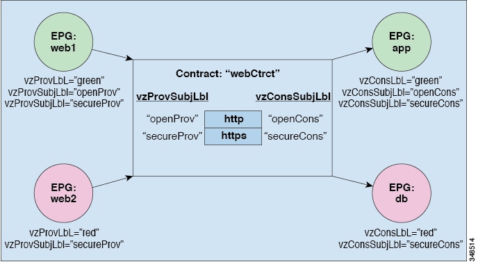
The four EPGs are named EPG:web1, EPG:web2, EPG:app, and EPG:db. EPG:web1 and EPG:web2 provide a contract called webCtrct. EPG:app and EPG:db consume that same contract.
EPG:web1 can only communicate with EPG:app and EPG:web2 can only communicate with EPG:db. This interaction is controlled through the provider and consumer labels “green” and “red”.
When EPG:web1 communicates with EPG:app, they use the webCtrct contract. EPG:app can initiate connections to EPG:web1 because it consumes the contract that EPG:web1 provides.
The subjects that EPG:web1 and EPG:app can use to communicate are both http and https because EPG:web1 has the provider subject label “openProv” and the http subject also has it. EPG:web1 has the provider subject label “secureProv” as does the subject https. In a similar fashion, EPG:app has subject labels “openCons” and “secureCons” that subjects http and https have.
When EPG:web2 communicates with EPG:db, they can only use the https subject because only the https subject carries the provider and consumer subject labels. EPG:db can initiate the TCP connection to EPG:web2 because EPG:db consumes the contract provided by EPG:web2.
Application Profiles Contain EPGs and All the Necessary Networking Constructs for Their Communication Requirements
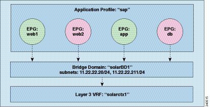
The example policy specifies the relationship between EPGs, application profiles, bridge domains, and Layer 3 contexts in the following manner: the EPGs EPG:web1, EPG:web2, EPG:app, and EPG:db are all members of the application profile called “sap”.
These EPGs are also linked to the bridge domain “solarBD1”. solarBD1 has two subnets, 11.22.22.XX/24 and 11.22.23.XX/24. The endpoints in the four EPGs must be within these two subnet ranges. The IP address of the default gateway in those two subnets will be 11.22.22.20 and 11.22.23.211. The solarBD1 bridge domain is linked to the “solarctx1” Layer 3 context.
All these policy details are contained within a tenant called “solar”.
Managed Object Relations and Policy Resolution
Relationship managed objects express the relation between managed object instances that do not share containment (parent-child) relations. MO relations are established between the source MO and a target MO in one of the following two ways:
-
An explicit relation (
fvRsPathAtt) defines a relationship based on the target MO domain name (DN). -
A named relation defines a relationship based on the target MO name.
The dotted lines in the following figure shows several common MO relations.
MO Relations
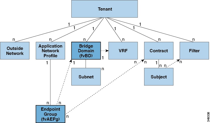
For example, the dotted line between the EPG and the bridge domain defines the relation between those two MOs. In this figure,
the EPG (fvAEPg) contains a relationship MO (fvRsBD) that is named with the name of the target bridge domain MO (fvDB). For example, if production is the bridge domain name (tnFvBDName=production), then the relation name would be production (fvRsBdName=production).
In the case of policy resolution based on named relations, if a target MO with a matching name is not found in the current tenant, the ACI fabric tries to resolve in the common tenant. For example, if the user tenant EPG contained a relationship MO targeted to a bridge domain that did not exist in the tenant, the system tries to resolve the relationship in the common tenant. If a named relation cannot be resolved in either the current tenant or the common tenant, the ACI fabric attempts to resolve to a default policy. If a default policy exists in the current tenant, it is used. If it does not exist, the ACI fabric looks for a default policy in the common tenant. Bridge domain, VRF, and contract (security policy) named relations do not resolve to a default.
Default Policies
The initial values of the APIC default policies values are taken from the concrete model that is loaded in the switch. A fabric administrator can modify default policies. A default policy serves multiple purposes:
-
Allows a fabric administrator to override the default values in the model.
-
If an administrator does not provide an explicit policy, the APIC applies the default policy. An administrator can create a default policy and the APIC uses that unless the administrator provides any explicit policy.
Default Policies
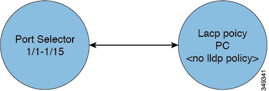
For example, according to actions the administrator does or does not take, the APIC will do the following:
-
Because the administrator does not specify the LLDP policy for the selected ports, the APIC applies the default LLDP interface policy for the ports specified in the port selector.
-
If the administrator removes a port from a port selector, the APIC applies the default policies to that port. In this example, if the administrator removes port 1/15 from the port selector, the port is no longer part of the port channel and the APIC applies all the default policies to that port.
When the ACI fabric is upgraded, the existing policy default values persist, even if the default value changes in the newer release. When the node connects to the APIC for the first time, the node registers itself with APIC which pushes all the default policies to the node. Any change in the default policy is pushed to the node.
The policy model specifies that an object is using another policy by having a relation managed object (MO) under that object
and that relation MO refers to the target policy by name. If this relation does not explicitly refer to a policy by name,
then the system will try to resolve a policy called default. Bridge domains (BD) and VRFs (Ctx) are exceptions to this rule.
Trans Tenant EPG Communications
EPGs in one tenant can communicate with EPGs in another tenant through a contract interface contained in a shared tenant. The contract interface is an MO that can be used as a contract consumption interface by the EPGs that are contained in different tenants. By associating to an interface, an EPG consumes the subjects represented by the interface to a contract contained in the shared tenant. Tenants can participate in a single contract, which is defined at some third place. More strict security requirements can be satisfied by defining the tenants, contract, subjects, and filter directions so that tenants remain completely isolated from one another.
Tags
Object tags simplify API operations. In an API operation, an object or group of objects can be referenced by the tag name instead of by the distinguished name (DN). Tags are child objects of the item they tag; besides the name, they have no other properties.
Use a tag to assign a descriptive name to a group of objects. The same tag name can be assigned to multiple objects. Multiple tag names can be assigned to an object. For example, to enable easy searchable access to all web server EPGs, assign a web server tag to all such EPGs. Web server EPGs throughout the fabric can be located by referencing the web server tag.
About APIC Quota Management Configuration
Starting in the Cisco Application Policy Infrastructure Controller (APIC) Release 2.3(1), there are limits on number of objects a tenant admin can configure. This enables the admin to limit what managed objects that can be added under a given tenant or globally across tenants.
This feature is useful when you want to limit any tenant or group of tenants from exceeding ACI maximums per leaf or per fabric or unfairly consuming a majority of available resources, potentially affecting other tenants on the same fabric
Fabric Policies Overview
Fabric policies govern the operation of internal fabric interfaces and enable the configuration of various functions, protocols, and interfaces that connect spine and leaf switches. Administrators who have fabric administrator privileges can create new fabric policies according to their requirements. The APIC enables administrators to select the pods, switches, and interfaces to which they will apply fabric policies. The following figure provides an overview of the fabric policy model.
Fabric Polices Overview
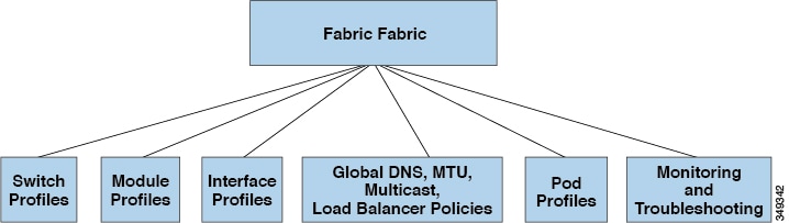
Fabric policies are grouped into the following categories:
-
Switch profiles specify which switches to configure and the switch configuration policy.
-
Module profiles specify which spine switch modules to configure and the spine switch configuration policy.
-
Interface profiles specify which fabric interfaces to configure and the interface configuration policy.
-
Global policies specify DNS, fabric MTU default, multicast tree, and load balancer configurations to be used throughout the fabric.
-
Pod profiles specify date and time, SNMP, council of oracle protocol (COOP), IS-IS and Border Gateway Protocol (BGP) route reflector policies.
-
Monitoring and troubleshooting policies specify what to monitor, thresholds, how to handle faults and logs, and how to perform diagnostics.
Access Policies Overview
Access policies configure external-facing interfaces that connect to devices such as virtual machine controllers and hypervisors, hosts, network attached storage, routers, or Fabric Extender (FEX) interfaces. Access policies enable the configuration of port channels and virtual port channels, protocols such as Link Layer Discovery Protocol (LLDP), Cisco Discovery Protocol (CDP), or Link Aggregation Control Protocol (LACP), and features such as statistics gathering, monitoring, and diagnostics. The following figure provides an overview of the access policy model.
Access Policy Model Overview
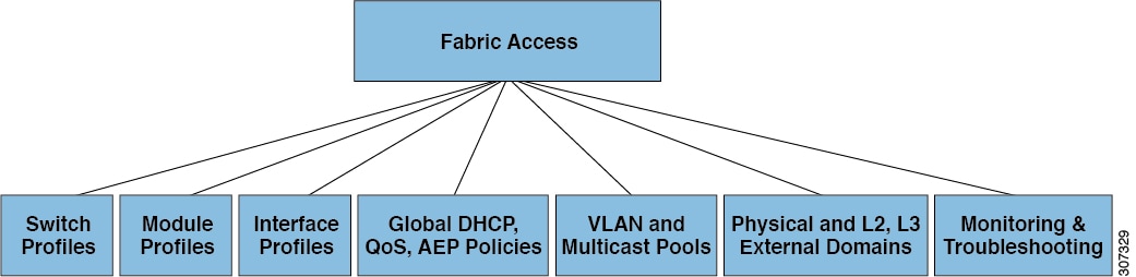
Access policies are grouped into the following categories:
-
Switch profiles specify which switches to configure and the switch configuration policy.
-
Module profiles specify which leaf switch access cards and access modules to configure and the leaf switch configuration policy.
-
Interface profiles specify which access interfaces to configure and the interface configuration policy.
-
Global policies enable the configuration of DHCP, QoS, and attachable access entity (AEP) profile functions that can be used throughout the fabric. AEP profiles provide a template to deploy hypervisor policies on a large set of leaf ports and associate a Virtual Machine Management (VMM) domain and the physical network infrastructure. They are also required for Layer 2 and Layer 3 external network connectivity.
-
Pools specify VLAN, VXLAN, and multicast address pools. A pool is a shared resource that can be consumed by multiple domains such as VMM and Layer 4 to Layer 7 services. A pool represents a range of traffic encapsulation identifiers (for example, VLAN IDs, VNIDs, and multicast addresses).
-
Physical and external domains policies include the following:
-
External bridged domain Layer 2 domain profiles contain the port and VLAN specifications that a bridged Layer 2 network connected to the fabric uses.
-
External routed domain Layer 3 domain profiles contain the port and VLAN specifications that a routed Layer 3 network connected to the fabric uses.
-
Physical domain policies contain physical infrastructure specifications, such as ports and VLAN, used by a tenant or endpoint group.
-
-
Monitoring and troubleshooting policies specify what to monitor, thresholds, how to handle faults and logs, and how to perform diagnostics.
Contracts Contain Security Policy Specifications
In the ACI security model, contracts contain the policies that govern the communication between EPGs. The contract specifies what can be communicated and the EPGs specify the source and destination of the communications. Contracts link EPGs, as shown below.
EPG 1 — — — — — — —- CONTRACT — — — — — — —- EPG 2
Endpoints in EPG 1 can communicate with endpoints in EPG 2 and vice versa if the contract allows it. This policy construct is very flexible. There can be many contracts between EPG 1 and EPG 2, there can be more than two EPGs that use a contract, and contracts can be reused across multiple sets of EPGs, and more.
There is also directionality in the relationship between EPGs and contracts. EPGs can either provide or consume a contract. An EPG that provides a contract is typically a set of endpoints that provide a service to a set of client devices. The protocols used by that service are defined in the contract. An EPG that consumes a contract is typically a set of endpoints that are clients of that service. When the client endpoint (consumer) tries to connect to a server endpoint (provider), the contract checks to see if that connection is allowed. Unless otherwise specified, that contract would not allow a server to initiate a connection to a client. However, another contract between the EPGs could easily allow a connection in that direction.
This providing/consuming relationship is typically shown graphically with arrows between the EPGs and the contract. Note the direction of the arrows shown below.
EPG 1 < — — —-consumes — — — — CONTRACT < — — —-provides — — — — EPG 2
The contract is constructed in a hierarchical manner. It consists of one or more subjects, each subject contains one or more filters, and each filter can define one or more protocols.
Contract Filters
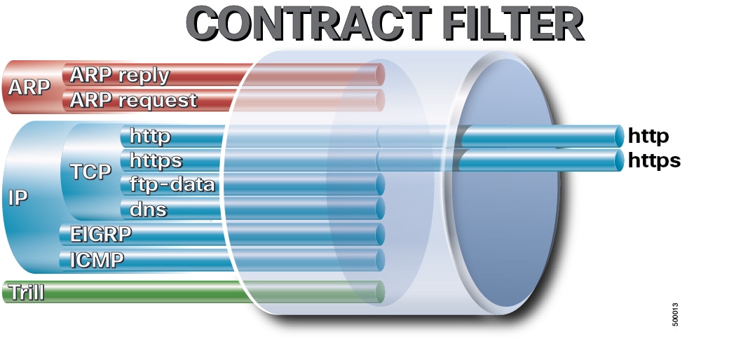
The following figure shows how contracts govern EPG communications.
Contracts consist of 1 or more subjects. Each subject contains 1 or more filters. Each filter contains 1 or more entries. Each entry is equivalent to a line in an Access Control List (ACL) that is applied on the Leaf switch to which the endpoint within the endpoint group is attached. The following figure shows the components of a contract.
Contract Components
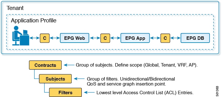
In detail, contracts are comprised of the following items:
-
Name—All contracts that are consumed by a tenant must have different names (including contracts created under the common tenant or the tenant itself).
-
Subjects—A group of filters for a specific application or service.
-
Scope—Global, tenant, VRF, Application Profile.
-
Filters—Used to classify traffic based upon layer 2 to layer 4 attributes (such as Ethernet type, protocol type, TCP flags and ports).
-
Actions—Action to be taken on the filtered traffic. The following actions are supported:
-
Permit the traffic (regular contracts, only)
-
Mark the traffic (DSCP/CoS) (regular contracts, only)
-
Redirect the traffic (regular contracts, only, through a service graph)
-
Copy the traffic (regular contracts, only, through a service graph or SPAN)
-
Block the traffic (taboo contracts)
-
With Cisco APIC Release 3.2(x) and switches with names that end in EX or FX, you can alternatively use a subject Deny action or Contract or Subject Exception in a standard contract to block traffic with specified patterns.
-
Log the traffic (taboo contracts and regular contracts).
-
Aliases—(Optional) A changeable name for an object. Although the name of an object, once created, cannot be changed, the Alias is a property that can be changed.
Thus, the contract allows more complex actions than just allow or deny. The contract can specify that traffic that matches a given subject can be re-directed to a service, can be copied, or can have its QoS level modified. With pre-population of the access policy in the concrete model, endpoints can move, new ones can come on-line, and communication can occur even if the APIC is off-line or otherwise inaccessible. The APIC is removed from being a single point of failure for the network. Upon packet ingress to the ACI fabric, security policies are enforced by the concrete model running in the switch.
Security Policy Enforcement
As traffic enters the leaf switch from the front panel interfaces, the packets are marked with the EPG of the source EPG. The leaf switch then performs a forwarding lookup on the packet destination IP address within the tenant space. A hit can result in any of the following scenarios:
-
A unicast (/32) hit provides the EPG of the destination endpoint and either the local interface or the remote leaf switch VTEP IP address where the destination endpoint is present.
-
A unicast hit of a subnet prefix (not /32) provides the EPG of the destination subnet prefix and either the local interface or the remote leaf switch VTEP IP address where the destination subnet prefix is present.
-
A multicast hit provides the local interfaces of local receivers and the outer destination IP address to use in the VXLAN encapsulation across the fabric and the EPG of the multicast group.
A miss result in the forwarding table causes the packet to be sent to the forwarding proxy in the spine switch. The forwarding proxy then performs a forwarding table lookup. If it is a miss, the packet is dropped. If it is a hit, the packet is sent to the egress leaf switch that contains the destination endpoint. Because the egress leaf switch knows the EPG of the destination, it performs the security policy enforcement. The egress leaf switch must also know the EPG of the packet source. The fabric header enables this process because it carries the EPG from the ingress leaf switch to the egress leaf switch. The spine switch preserves the original EPG in the packet when it performs the forwarding proxy function.
On the egress leaf switch, the source IP address, source VTEP, and source EPG information are stored in the local forwarding table through learning. Because most flows are bidirectional, a return packet populates the forwarding table on both sides of the flow, which enables the traffic to be ingress filtered in both directions.
DHCP Relay
Although ACI fabric-wide flooding is disabled by default, flooding within a bridge domain is enabled by default. Because flooding within a bridge domain is enabled by default, clients can connect to DHCP servers within the same EPG. However, when the DHCP server is in a different EPG or Virtual Routing and Forwarding (VRF) instance than the clients, DHCP Relay is required. Also, when Layer 2 flooding is disabled, DHCP Relay is required.
The figure below shows the managed objects in the management information tree (MIT) that can contain DHCP relays: user tenants, the common tenant, the infra tenant, the mgmt tenant, and fabric access.
DHCP Relay Locations in the MIT
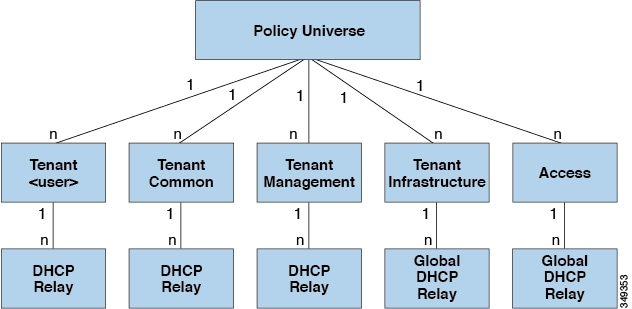
The figure below shows the logical relationships of the DHCP relay objects within a user tenant.
Tenant DHCP Relay
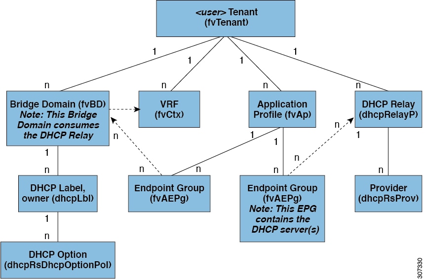
The DHCP Relay profile contains one or more providers. An EPG contains one or more DHCP servers, and the relation between the EPG and DHCP Relay specifies the DHCP server IP address. The consumer bridge domain contains a DHCP label that associates the provider DHCP server with the bridge domain. Label matching enables the bridge domain to consume the DHCP Relay.
Note |
The bridge domain DHCP label must match the DHCP Relay name. |
The DHCP label object also specifies the owner. The owner can be a tenant or the access infrastructure. If the owner is a tenant, the ACI fabric first looks within the tenant for a matching DHCP Relay. If there is no match within a user tenant, the ACI fabric then looks in the common tenant.
DHCP Relay operates in the Visable mode as follows: Visible—the provider's IP and subnet are leaked into the consumer's VRF. When the DHCP Relay is visible, it is exclusive to the consumer's
VRF.
While the tenant and access DHCP Relays are configured in a similar way, the following use cases vary accordingly:
-
Common tenant DHCP Relays can be used by any tenant.
-
Infra tenant DHCP Relays are exposed selectively by the ACI fabric service provider to other tenants.
-
Fabric Access (
infraInfra) DHCP Relays can be used by any tenant and allow more granular configuration of the DHCP servers. In this case, it is possible to provision separate DHCP servers within the same bridge domain for each leaf switch in the node profile.
DNS
The ACI fabric DNS service is contained in the fabric managed object. The fabric global default DNS profile can be accessed throughout the fabric. The figure below shows the logical relationships of the DNS-managed objects within the fabric.
DNS
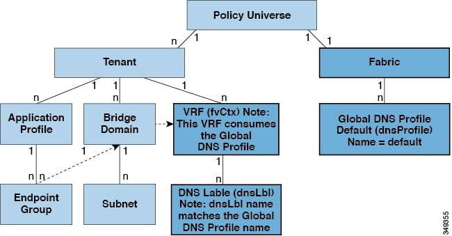
A VRF (context) must contain a dnsLBL object in order to use the global default DNS service. Label matching enables tenant VRFs to consume the global DNS provider.
Because the name of the global DNS profile is “default,” the VRF label name is "default" (dnsLBL name = default).
In-Band and Out-of-Band Management Access
The mgmt tenant provides a convenient means to configure access to fabric management functions. While fabric management functions are accessible through the APIC, they can also be accessed directly through in-band and out-of-band network policies.
Static and Dynamic Management Access
APIC supports both static and dynamic management access. For simple deployments where users manage the IP addresses of a few leaf and spine switches, configuring static in-band and out-of-band management connectivity is simpler. For more complex deployments, where you might have a large number of leaf and spine switches that require managing many IP addresses, static management access is not recommended. For detailed information about static management access, see Cisco APIC and Static Management Access.
In-Band Management Access
The following figure shows an overview of the mgmt tenant in-band fabric management access policy.
In-Band Management Access Policy
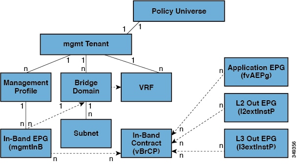
The management profile includes the in-band EPG MO that provides access to management functions via the in-band contract (vzBrCP). The vzBrCP enables fvAEPg, l2extInstP, andl3extInstP EPGs to consume the in-band EPG. This exposes the fabric management to locally connected devices, as well as devices connected
over Layer 2 bridged external networks, and Layer 3 routed external networks. If the consumer and provider EPGs are in different
tenants, they can use a bridge domain and VRF from the common tenant. Authentication, access, and audit logging apply to these
connections; any user attempting to access management functions through the in-band EPG must have the appropriate access privileges.
The figure below shows an in-band management access scenario.
Out-of-Band Management Access
The following figure shows an overview of the mgmt tenant out-of-band fabric management access policy.
Out-of-Band Management Access Policy
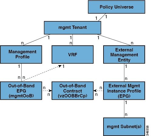
The management profile includes the out-of-band EPG MO that provides access to management functions via the out-of-band contract
(vzOOBBrCP). The vzOOBBrCP enables the external management instance profile (mgmtExtInstP) EPG to consume the out-of-band EPG. This exposes the fabric node supervisor ports to locally or remotely connected devices,
according to the preference of the service provider. While the bandwidth of the supervisor ports will be lower than the in-band
ports, the supervisor ports can provide direct access to the fabric nodes when access through the in-band ports is unavailable.
Authentication, access, and audit logging apply to these connections; any user attempting to access management functions through
the out-of-band EPG must have the appropriate access privileges. When an administrator configures an external management instance
profile, it specifies a subnet range for devices that are allowed out-of-band access. Any device not in this range will not
have out-of-band access.
WAN and Other External Networks
External routers that connect to the WAN and the enterprise core connect to the front panel interfaces of the leaf switch. The leaf switch interface that connects to the external router can be configured as a bridged interface or a routing peer.
Networking Domains
A fabric administrator creates domain policies that configure ports, protocols, VLAN pools, and encapsulation. These policies can be used exclusively by a single tenant, or shared. Once a fabric administrator configures domains in the ACI fabric, tenant administrators can associate tenant endpoint groups (EPGs) to domains.
The following networking domain profiles can be configured:
-
VMM domain profiles (
vmmDomP) are required for virtual machine hypervisor integration. -
Physical domain profiles (
physDomP) are typically used for bare metal server attachment and management access. -
Bridged outside network domain profiles (
l2extDomP) are typically used to connect a bridged external network trunk switch to a leaf switch in the ACI fabric. -
Routed outside network domain profiles (
l3extDomP) are used to connect a router to a leaf switch in the ACI fabric. - Fibre Channel domain profiles (
fcDomP) are used to connect Fibre Channel VLANs and VSANs.
A domain is configured to be associated with a VLAN pool. EPGs are then configured to use the VLANs associated with a domain.
Bridged and Routed Connectivity to External Networks
Outside network managed objects enable Layer 2 and Layer 3 tenant connectivity to external networks. The GUI, CLI, or REST API can be used to configure tenant connectivity to external networks. To easily locate the external network access points in the fabric, Layer 2 and Layer 3 external leaf nodes can be tagged as "Border Leaf Nodes."
Layer 2 Out for Bridged Connectivity to External Networks
Tenant Layer 2 bridged connectivity to external networks is enabled by associating a fabric access (infraInfra) external bridged domain (L2extDomP) with the Layer 2 external instance profile (l2extInstP) EPG of a Layer 2 external outside network (l2extOut) as shown in the figure below.
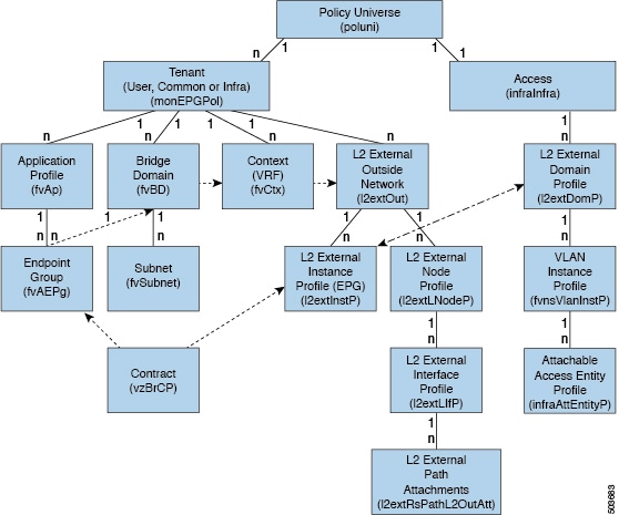
The l2extOut includes the switch-specific configuration and interface-specific configuration. The l2extInstP EPG exposes the external network to tenant EPGs through a contract. For example, a tenant EPG that contains a group of network-attached
storage devices could communicate through a contract with the l2extInstP EPG according to the network configuration contained in the Layer 2 external outside network. Only one outside network can
be configured per leaf switch. However, the outside network configuration can easily be reused for multiple nodes by associating
multiple nodes with the L2 external node profile. Multiple nodes that use the same profile can be configured for fail-over
or load balancing.
Bridged Interface to an External Router
As shown in the figure below, when the leaf switch interface is configured as a bridged interface, the default gateway for the tenant VNID is the external router. The ACI fabric is unaware of the presence of the external router and the APIC statically assigns the leaf switch interface to its EPG.
Layer 3 Out for Routed Connectivity to External Networks
Routed connectivity to external networks is enabled by associating a fabric access (infraInfra) external routed domain (l3extDomP) with a tenant Layer 3 external instance profile (l3extInstP or external EPG) of a Layer 3 external outside network (l3extOut), in the hierarchy in the following diagram:
Policy Model for Layer 3 External Connections

A Layer 3 external outside network (l3extOut object) includes the routing protocol options (BGP, OSPF, or EIGRP or supported combinations) and the switch-specific and
interface-specific configurations. While the l3extOut contains the routing protocol (for example, OSPF with its related Virtual Routing and Forwarding (VRF) and area ID), the
Layer 3 external interface profile contains the necessary OSPF interface details. Both are needed to enable OSPF.
The l3extInstP EPG exposes the external network to tenant EPGs through a contract. For example, a tenant EPG that contains a group of web
servers could communicate through a contract with the l3extInstP EPG according to the network configuration contained in the l3extOut. The outside network configuration can easily be reused for multiple nodes by associating the nodes with the L3 external
node profile. Multiple nodes that use the same profile can be configured for fail-over or load balancing. Also, a node can
be added to multiple l3extOuts resulting in VRFs that are associated with the l3extOuts also being deployed on that node.
For scalability information, refer to the current Verified Scalability Guide for Cisco ACI.
Cisco ACI Support for Virtual Machine Managers
Cisco ACI virtual machine (VM) networking supports hypervisors from multiple vendors. It provides the hypervisors programmable and automated access to high-performance scalable virtualized data center infrastructure.
Programmability and automation are critical features of scalable data center virtualization infrastructure. The Cisco ACI open REST API enables virtual machine integration with and orchestration of the policy model-based Cisco ACI fabric. Cisco ACI VM networking enables consistent enforcement of policies across both virtual and physical workloads managed by hypervisors from multiple vendors.
Attachable entity profiles easily enable VM mobility and placement of workloads anywhere in the Cisco ACI fabric. The Cisco Application Policy Infrastructure Controller (APIC) provides centralized troubleshooting, application health score, and virtualization monitoring. Cisco ACI multi-hypervisor VM automation reduces or eliminates manual configuration and manual errors. This enables virtualized data centers to support large numbers of VMs reliably and cost effectively.
VMM Domain Policy Model
VMM domain profiles (vmmDomP) specify connectivity policies that enable virtual machine controllers to connect to the ACI fabric. The figure below provides
an overview of the vmmDomP policy.
VMM Domain Policy Model Overview
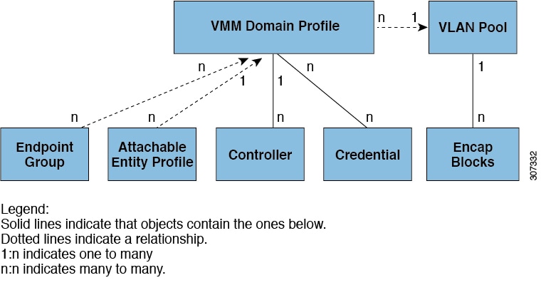
Virtual Machine Manager Domain Main Components
ACI fabric virtual machine manager (VMM) domains enable an administrator to configure connectivity policies for virtual machine controllers. A single VMM domain can contain multiple instances of VM controllers, but they must be from the same vendor (for example, from VMware or from Microsoft. An APIC VMM domain profile is a policy that defines a VMM domain. The VMM domain policy is created in APIC and pushed into the leaf switches. The essential components of an ACI VMM domain policy include the following:
-
Virtual Machine Manager Domain Profile—Groups VM controllers with similar networking policy requirements. For example, VM controllers can share VLAN pools and application endpoint groups (EPGs). The APIC communicates with the controller to publish network configurations such as port groups that are then applied to the virtual workloads. The VMM domain profile includes the following essential components:
-
Credential—Associates a valid VM controller user credential with an APIC VMM domain.
-
Controller—Specifies how to connect to a VM controller that is part of a policy enforcement domain. For example, the controller specifies the connection to a VMware vCenter that is part a VMM domain.
-
EPG Association—Endpoint groups regulate connectivity and visibility among the endpoints within the scope of the VMM domain policy. VMM domain EPGs behave as follows:
-
The APIC pushes these EPGs as port groups into the VM controller.
-
An EPG can span multiple VMM domains, and a VMM domain can contain multiple EPGs.
-
Attachable Entity Profile Association—Associates a VMM domain with the physical network infrastructure. An attachable entity profile (AEP) is a network interface template that enables deploying VM controller policies on a large set of leaf switch ports. An AEP specifies which switches and ports are available, and how they are configured.
-
VLAN Pool Association—A VLAN pool specifies the VLAN IDs or ranges used for VLAN encapsulation that the VMM domain consumes.
-
A VMM domain inventories controller elements (such as pNICs, vNICs, VM names, and so forth) and pushes policies into the controller(s), creating port groups, and other necessary elements. The ACI VMM domain listens for controller events such as VM mobility and responds accordingly.
VLAN pools represent blocks of traffic VLAN identifiers. A VLAN pool is a shared resource and can be consumed by multiple domains such as VMM domains and Layer 4 to Layer 7 services.
Each pool has an allocation type (static or dynamic), defined at the time of its creation. The allocation type determines whether the identifiers contained in it will be used for automatic assignment by the APIC (dynamic) or set explicitly by the administrator (static). By default, all blocks contained within a VLAN pool have the same allocation type as the pool but users can change the allocation type for encapsulation blocks contained in dynamic pools to static. Doing so excludes them from dynamic allocation.
A VMM domain can associate with only one dynamic VLAN pool. By default, the assignment of VLAN identifiers to EPGs that are associated with VMM domains is done dynamically by the APIC. While dynamic allocation is the default and preferred configuration, an administrator can statically assign a VLAN identifier to an EPG instead. In that case, the identifiers used must be selected from encapsulation blocks in the VLAN pool associated with the VMM domain, and their allocation type must be changed to static.
The APIC provisions VMM domain VLAN on leaf ports based on EPG events, either statically binding on leaf ports or based on VM events from controllers such as VMware vCenter or Microsoft SCVMM.
VMM Domain EPG Association
The ACI fabric associates tenant application profile EPGs to VMM domains, either automatically by an orchestration component such as OpenStack or Microsoft Azure, or by an APIC administrator creating such configurations. An EPG can span multiple VMM domains and a VMM domain can contain multiple EPGs.
EPGs can use multiple VMM domains in the following ways:
- An EPG within a VMM domain is identified by using an encapsulation identifier that is either automatically managed by the APIC, or statically selected by the administrator. An example is a VLAN, a Virtual Network ID (VNID).
- An EPG can be mapped to multiple physical (for bare metal servers) or virtual domains. It can use different VLAN or VNID encapsulations in each domain.
Applications can be deployed across VMM domains.
Layer 4 to Layer 7 Service Insertion
The Cisco Application Policy Infrastructure Controller (APIC) manages network services. Policies are used to insert services. APIC service integration provides a life cycle automation framework that enables the system to dynamically respond when a service comes online or goes offline. Shared services that are available to the entire fabric are administered by the fabric administrator. Services that are for a single tenant are administered by the tenant administrator.
The APIC provides automated service insertion while acting as a central point of policy control. APIC policies manage both the network fabric and services appliances. The APIC can configure the network automatically so that traffic flows through the services. Also, the APIC can automatically configure the service according to the application's requirements. This approach allows organizations to automate service insertion and eliminate the challenge of managing all of the complex traffic-steering techniques of traditional service insertion.
Layer 4 to Layer 7 Policy Model
The Layer 4 to Layer 7 service device type policies includes key managed objects such as services supported by the package and device scripts. The following figure shows the objects of the Layer 4 to Layer 7 service device type policy model.
Layer 4 to Layer 7 Policy Model
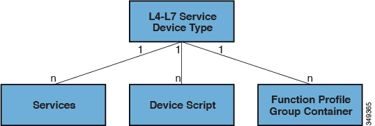
Layer 4 to Layer 7 service policies contain the following:
-
Services—Contains metadata for all the functions provided by a device such as SSL offloading and load-balancing. This MO contains the connector names, encapsulation type, such as VLAN and VXLAN, and any interface labels.
-
Device Script—Represents a device script handler that contains meta information about the related attributes of the script handler including its name, package name, and version.
-
Function Profile Group Container—Objects that contain the functions available to the service device type. Function profiles contain all the configurable parameters supported by the device organized into folders.
Configuring Monitoring Policies
Administrators can create monitoring policies with the following four broad scopes:
-
Fabric Wide: includes both fabric and access objects
-
Access (also known as infrastructure): access ports, FEX, VM controllers, and so on
-
Fabric: fabric ports, cards, chassis, fans, and so on
-
Tenant: EPGs, application profiles, services, and so on
-
The APIC includes the following four classes of default monitoring policies:
-
monCommonPol(uni/fabric/moncommon): applies to both fabric and access infrastructure hierarchies -
monFabricPol(uni/fabric/monfab-default): applies to fabric hierarchies -
monInfraPol(uni/infra/monifra-default): applies to the access infrastructure hierarchy -
monEPGPol(uni/tn-common/monepg-default): applies to tenant hierarchies
-
In each of the four classes of monitoring policies, the default policy can be overridden by a specific policy. For example,
a monitoring policy applied to the Solar tenant (tn-solar) would override the default one for the Solar tenant while other tenants would still be monitored by the default policy.
Each of the four objects in the figure below contains monitoring targets.
Four Classes of Default Monitoring Policies
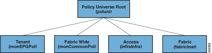
The Infra monitoring policy contains monInfra targets, the fabric monitoring policy contains monFab targets, and the tenant monitoring policy contains monEPG
targets. Each of the targets represent the corresponding class of objects in this hierarchy. For example, under the monInfra
-default monitoring policy, there is a target representing FEX fabric-facing ports. The policy details regarding how to monitor these
FEX fabric-facing ports are contained in this target. Only policies applicable to a target are allowed under that target.
Note that not all possible targets are auto-created by default. The administrator can add more targets under a policy if the
target is not there.
The common monitoring policy (monCommonPol) has global fabric-wide scope and is automatically deployed on all nodes in the fabric, including the APIC controllers. Any
source (such as syslog, callhome, or snmp) located under the common monitoring policy captures all faults, events, audits
and health occurrences. The single common monitoring policy monitors the whole fabric. The threshold of the severity for syslog
and snmp or urgency for callhome can be configured according to the level of detail that a fabric administrator determines
is appropriate.
Multiple monitoring policies can be used to monitor individual parts of the fabric independently. For example, a source under the global monitoring policy reflects a global view. Another source under acustom monitoring policy deployed only to some nodes could closely monitor their power supplies. Or, specific fault or event occurrences for different tenants could be redirected to notify specific operators.
Sources located under other monitoring policies capture faults, events and audits within a smaller scope. A source located
directly under a monitoring policy, captures all occurrences within the scope (for example fabric, infra, etc.). A source
located under a target, captures all occurrences related to that target (for example, eqpt:Psu for power supply). A source located under a fault/event severity assignment policy captures only the occurrences that match
that particular fault or event as identified by the fault/event code.
When a fault/event/audit is generated, all applicable sources are used. For example consider the following for the configuration below:
-
Syslog source 4, pointing to syslog group 4 is defined for fault F0123.
-
Syslog source 3, pointing to syslog group 3 is defined for target power supply (
eqpt:Psu). -
Syslog source 2, pointing to syslog group 2 is defined for scope infra.
-
Syslog source 1, pointing to syslog group 1 is defined for the common monitoring policy.
If fault F0123 occurs on an MO of class eqpt:Psu in scope infra, a syslog message is sent to all the destinations in syslog groups 1-4, assuming the severity of the message is at or above the minimum defined for each source and destination. While this example illustrates a syslog configuration, callhome and SNMP configurations would operate in the same way.
Monitoring policies can also be configured for other system operations, such as faults or health scores. The structure of monitoring policies map to this hierarchy:
Monitoring Policy
-
Statistics Export
-
Collection Rules
-
Monitoring Targets
-
Statistics Export
-
Collection Rules
-
Statistics
-
Collection Rules
-
Thresholds Rules
-
Statistics Export
Statistics Export policies option in the following figure define the format and destination for statistics to be exported. The output can be exported using FTP, HTTP, or SCP protocols. The format can be JSON or XML. The user or administrator can also choose to compress the output. Export can be defined under Statistics, Monitoring Targets, or under the top-level monitoring policy. The higher-level definition of Statistics Export takes precedence unless there is a defined lower-level policy.
Monitoring policies are applied to specific observable objects (such as ports, cards, EPGs, and tenants) or groups of observable objects by using selectors or relations.
Monitoring policies define the following:
-
Statistics are collected and retained in the history.
-
Threshold crossing faults are triggered.
-
Statistics are exported.
Collection Rules are defined per sampling interval. They configure whether the collection of statistics should be turned on or off, and when turned on, what the history retention period should be. Monitoring Targets correspond to observable objects (such as ports and EPGs).
Statistics correspond to groups of statistical counters (such as ingress-counters, egress-counters, or drop-counters).
Collection Rules can be defined. The higher-level definition of Collection Rules takes precedence unless there is a defined lower-level policy.
Threshold rules are defined under collection rules and would be applied to the corresponding sampling-interval that is defined in the parent collection rule.
 Feedback