FabricPath to ACI Migration Cisco Validated Design Guide
Available Languages
FabricPath to ACI Migration Cisco Validated Design Guide
First Published: September 1, 2014
Last Updated: May 5, 2017
Contents
¯ Preface
¯ Audience
¯ Scope
■ Initial Design Considerations
¯ Management Out-of-Band and In-Band
¯ Connectivity With VLAN to EPG Static Mappings
¯ Scenario 1: Mapping a VLAN to Multiple EPGs
¯ Scenario 2: Mapping VLANs to EPGs (1:1)
■ Infrastructure Deployment Considerations
¯ FabricPath Enabled Datacenter
¯ ACI Infrastructure Deployment
¯ Fabric Access Policy Configuration
¯ Integration Phase – Scenario 1
¯ Migration Phase – Scenario 1
¯ Fabric Access Policy Configuration
¯ Integration Phase – Scenario 2
¯ Migration Phase – Scenario 2
¯ UCS B-series and ACI integration considerations
¯ ACI Object Naming Conventions
■ Obtaining Documentation and Submitting a Service Request
Introduction
Preface
This document describes the migration procedures that can be adopted to move workloads and applications between a Brownfield environment and a new Greenfield ACI fabric. Different use cases are discussed, including the migration of network services and of the connectivity to the external Layer 3 network.
Audience
This document is intended for use by network architects and engineers to aid in developing operational-based solutions for Cisco ACI.
Scope
The scope of this document is to specifically cover Cisco ACI concepts for implementing an operational model for the ACI fabric. Limited background information is included on other related components whose understanding is required for the solution implementation. For more background information on ACI please refer to the following link: http://www.cisco.com/go/aci.
The following documents discuss Cisco ACI design and deployment considerations, which are useful prerequisites:
· Cisco Application Centric Infrastructure Design Guide:
http://www.cisco.com/c/en/us/solutions/collateral/data-center-virtualization/application-centric-infrastructure/white-paper-c11-731960.html
· Cisco Application Centric Infrastructure (ACI) - Endpoint Groups (EPG) Usage and Design:
http://www.cisco.com/c/en/us/solutions/collateral/data-center-virtualization/application-centric-infrastructure/white-paper-c11-731630.html
Advantages to Adopting Cisco ACI
Cisco Application Centric Infrastructure (ACI) is an innovative secure architecture that delivers centralized application-driven policy automation, management, and visibility of physical and virtual networks. ACI is built upon a fabric foundation that delivers the best-in-class infrastructure by combining hardware, software, and ASIC innovations into an integrated system.
ACI provides significant advantages over a FabricPath-based network, and some of those are listed as follows:
| Areas |
FabricPath |
ACI Fabric |
ACI Technical Advantages |
ACI Business Advantages |
| Fabric Technology |
routing |
VXLAN, bridging, gateway, vPC |
· Enables a reliable, yet flexible placement of multitenant segments throughout the data center. · Enables better utilization of available network paths in the underlying infrastructure. |
· Reduces time to market for new services in a reliable manner · Enables an easy, modular, and scalable approach to deploy and place application workloads anywhere in the data center |
| Fabric Technology Enhancements |
N/A |
Enhanced VXLAN |
· Enhanced VXLAN provides advanced capabilities such as atomic counters and fabric-wide security. · ACI-vCenter integration means VNIDs are where you need them and when, instead of needing to configure them on all switches, which helps scale effectively. · Complete overlay visibility and troubleshooting insight. |
· Increase in application performance reflects directly on improved customer experience and ease of use of business and consumer services · Increased reliability due to proactive problem resolution |
| Endpoint (MAC/IP) Discovery |
Multicast, broadcast flooding |
Routing control plane |
· With routing control plane, ACI inherently increases stability, reliability, and security due to the use of routing and eliminating broadcast, multicast-based endpoint (MAC) discovery · Combines the efficiency of Layer 3 routing and VXLAN to provide a highly flexible, secure, and scalable solution |
· A more stable, reliable, and secure fabric directly contributes to customer success · Increases operational efficiency of customer staff |
| Management |
Per device |
A single system |
· Industry leading Cisco Nexus operating system · Even with hundreds of switches, ACI provides a single point of managing the fabric via Application Policy Infrastructure Controller (APIC). · Freedom from VNID/VLANID management on a per-switch basis · Unified firmware/software management control with rolling updgrade schedules |
· Substantial operational savings from eliminating hours of time and effort spent in managing hundreds of switches (including configuration, status checks, or upgrades) |
| Operations |
Per device |
Single system |
· As a single system, ACI provides complete application, network, and virtual compute visibility · Visibility: application health scores, fabric health scores, device health scores · Ability to perform impact analysis with reflection on what applications are impacted by network configuration changes (such as if a switch goes down, which EPGs/VLANs/VXLANs are impacted) · Subnet <> BD <> EPG independence (much simpler to implement than VXLANs/VXLANs on a large scale as would be needed in any legacy networking solution, including standalone) |
· End-to-end visibility reduces troubleshooting time of not only network infrastructure, but also for the virtual, compute, and application infrastructure · Increase in application performance reflects directly on improved customer experience and ease of use of business services |
| Security |
Per device |
Integrated |
· Automates security policy while allowing security teams to retain control over policies for compliance · Automated insertion of security services simplifies application deployments |
· Effectively addresses the ever-increasing concern around security · Improved security with faster provisioning · Simplified operations |
| Programmability |
XML, Python per device |
Fabric-wide APIs available on APIC |
· There is a single-point API for entire fabric · Support for OpFlex and device packages to extend fabric policy outside of the fabric |
· Consistency and agility across infrastructure · Flexible deployment, easier scaling, and lower TCO |
| Virtual Integration |
Not built in |
Readily available |
· Central deployment model accelerates network and security infrastructure configuration · Helps enable an any-workload, anywhere deployment model |
· Operational efficiency · Rapid deployment · Higher availability and increased customer satisfaction |
| L4 – L7 Integration |
No Automation |
Automated and tightly coupled |
Tightly coupled L4-L7 service automation enables automation of application lifecycle |
· Increase in application performance reflects directly on improved customer experience and ease of use of business services · End-to-end visibility reduces troubleshooting time of not only network infrastructure, but also for the virtual, compute, and application infrastructure |
| Application Intelligence |
Traditional VLAN-based |
Application Profiles, EPG-based grouping, Application Policy |
· Ability to define network policy by application definition · Contracts allow granular, simple control of interaction endpoint groups |
· Improves time to market, as application provision can be automated end-to-end and with ease · Operational improvement enabled by self-documenting data center through the APIC policy model · Provides real-time visibility into detailed information about application, compute, VMs, and associated policies · Improved security and management |
In a nutshell, the motivation for customers to adopt ACI is due to:
■ Having an out-of-box automated fabric
■ Deploying a solution versus independent devices
Some of the operational advantages offered by ACI are:
■ End-to-end visibility reduces troubleshooting time of not only network infrastructure, but also for the virtual, compute, and application infrastructure
■ Increase in application performance reflects directly on improved customer experience and ease of use of business services
■ Flexibility, control, and customization
■ Highly secure and scalable multitenancy
■ Proactive problem resolution and faster troubleshooting
■ Simplified operations
■ Applications delivered in business time
Initial Design Considerations
Extension Considerations
Extension Options
There are several options for extending from the ACI fabric to traditional environments (that is, spanning tree protocol (STP), vPC, and FabricPath). An in-depth explanation for each is not provided, but rather a pros and cons list, and an overview about which option most customers choose to deploy in their networks today.
If you would like to review extension options in detail, review the CCO white paper “Connecting Application Centric Infrastructure (ACI) to Outside and 3 Networks” using the following link: http://www.cisco.com/c/en/us/solutions/collateral/data-center-virtualization/application-centric-infrastructure/white-paper-c07-732033.html.
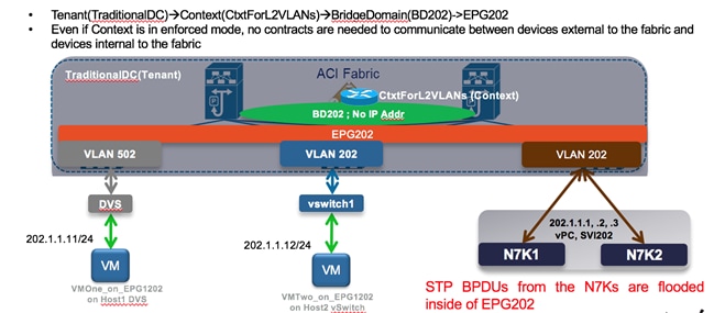
Connectivity via EPG – No Policy (L2Out via EPG)
This is the most popular option for extension to an ACI environment because via EPG is simple and straightforward. Users can extend an EPG beyond an ACI leaf by statically assigning a leaf port (along with a VLAN ID) to an EPG. After doing so, all the traffic received with the configured VLAN ID on this leaf port is mapped to the EPG and the configured policy for this EPG is enforced. The endpoints need not be directly connected to the ACI leaf port. They can be behind a network as long as the VLAN associated with the EPG is enabled within the network that connects the remote endpoint to the ACI fabric.
Consider the example in Figure 1 in which the following are shown:
1. Virtual workloads connected to a port group defined on an ACI-managed DVS and using VLAN tag 502 to send the traffic toward the ACI fabric.
2. Virtual workloads connected to a port group defined on a standard DVS not ACI-managed. From an ACI perspective, such endpoints are considered as belonging to a physical domain, hence static path bindings to a corresponding EPG is performed using VLAN tag 202.
3. Extension connectivity to an external network performed by creating a static path binding to a pair of Cisco Nexus 7000 switches using VLAN tag 202.
Note: The VLAN tags used for the static path bindings are only locally significant (on a per-interface basis), therefore there is no technical requirement to use the same 202 value shown in the following example.
Figure 1: L2Out via Static VLAN-EPG Mapping
Pros:
· Easiest of the solutions
· Straightforward
Cons:
· No contract enforcement between devices outside of the fabric (on the same broadcast domain) and devices inside the fabric, since they are all part of the same EPG202.
· STP TCNs, which are flooded from the Cisco Nexus 7000s, can result in traffic disruption as they cause the ACI fabric to flush the MAC address tables on the leaf nodes. There are mitigation steps to limit impact from this.
o Use vPC or double-sided vPC to connect ACI with STP environments.
o Enable the peer-switch feature with vPC (in the STP environment) that will eliminate root-bridge changes.
o Under the ACI BD configuration, enable flood mode for Layer 2 Unknown unicast packets. This will reduce the traffic disruption during an STP topology change.
Via BD – With Policy (L2Out via BD)
This section explains connectivity via a bridge domain (BD). Instead of extending from an EPG on the fabric, it is taken up a level and performs the extension from the BD. This enables the insertion of policy (that is, whitelist/contract functionality) between devices outside of the fabric (on the same broadcast domain) and devices inside of the fabric. Additionally, the STP TCN issue is marginally improved, as the STP TCNs are not flooded in EPGs attached to the BDs (only to the L2Out EPG).
Figure 2: L2Out via BD
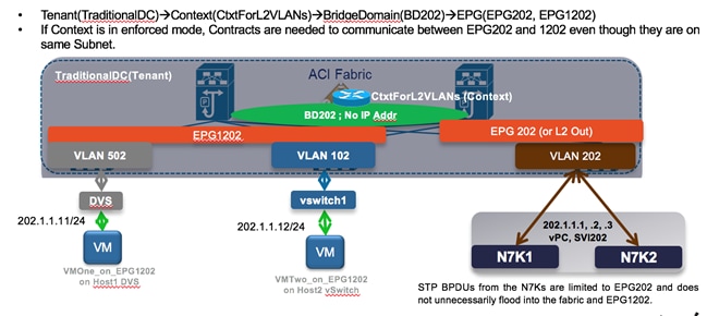
Pros: Contract enforcement is enabled between devices outside of the fabric (on the same broadcast domain) and devices inside the fabric.
Cons: More complex to deploy.
Connectivity via EPG – With Policy
If you need policy enforcement (contract functionality) enabled between devices outside of the fabric (on the same broadcast domain) and devices inside the fabric, but you don’t want the added complexity of the L2Out via BD, then Connectivity via EPG – With Policy is the recommended solution.
In the following figure, you can see the blending of the L2Out via EPG and L2Out via BD. There is an “Outside” EPG, which has connectivity via static path bindings to Nexus 7000s on the outside. Additionally, the “Outside” EPG also has static path bindings to a standard VMware DVS. The definition of an Outside EPG allows you to provide a contract to control the policy (communication) between “internal” EPGs (AppOneWeb, AppTwoWeb, and AppThreeWeb) and endpoints connected to the Outside EPG.
Note: This is the approach adopted for the migration scenarios discussed in this document.
Figure 3: L2Out via EPG (with Policy Enforcement)
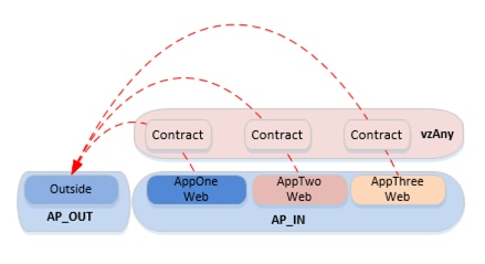
Pros: Allows the same Contract enforcement between devices outside of the fabric (on the same broadcast domain) and devices inside the fabric as the L2Out via BD, without the associated complexity.
Cons: Same STP TCN concerns as for the Layer 2 via EPG scenario.
ACI Interaction With STP Considerations
While ACI does not run STP, nor participate in STP environments, it does pass STP bridge protocol data units (BPDUs) it receives to other devices in the same EPG. For this reason, it is very important that the design takes this principle into account.
The following figure shows the three mechanisms currently used in ACI for loop detection.
Figure 4: ACI Loop Detetction Mechanisms
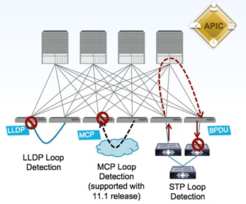
· LLDP Loop Detection: if an ACI leaf node receives on an edge port an LLDP frame generated by another leaf node part of the same fabric, the edge port is disabled.
· Mis-Cabling Protocol (MCP) Loop Detection: new link-level protocol sending MCP frames on all VLANs on all edge ports. If any ACI leaf receives on an edge port an MCP frame generated by another leaf part of the same ACI fabric, the edge port gets error-disabled.
· STP Loop Detection: when connecting to an outside network, the ACI fabric floods the received STP BPDU frames within the boundary of the EPG (by using the VXLAN network identifier (VNID) assigned for the EPG when it encapsulates the BPDU in VXLAN format). External switches are expected to break any potential loop upon receiving the flooded BPDU from the ACI fabric.
Regarding the STP loop detection mechanism, in order for the external network to be able to detect a Layer 2 loop, it is important that the VLAN ID mapped to an EPG is kept consistent across different interfaces. This requires attention when extending connectivity outside the fabric by leveraging static EPG to VLAN mapping, as discussed in the “Layer-2 Extension Options” section.
Figure 5: ACI and STP Interaction
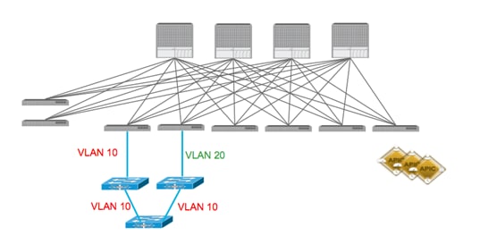
Figure 5 highlights what happens when that is not the case: the Layer 2 loop cannot be detected by the external Layer 2 switches, since a different VLAN tag is used on the two interfaces connecting them to the ACI fabric. Notice that this would not create an end-to-end Layer 2 loop in the data plane, but it may cause the Layer 2 switches to error-disable the interface that receives the BPDU for VLAN 10 on an interface configured as part of VLAN 20.
A couple of additional best practices when connecting an external Layer 2 network to the ACI fabric are captured as follows (and in the following diagrams):
· Never connect the same STP domain (Layer 2 network) to ACI fabric edge interfaces part of two different EPGs. Since the STP BPDUs are flooded inside the EPG, a Layer 2 loop created via the external Layer 2 domain cannot be detected in this case.
· Always ensure there is a single logical vPC connection between the ACI fabric and the external Layer 2 network domain.
Figure 6: STP and ACI Designs – STP Loop Free
In the example below, STP BPDUs are flooded inside of the EPG, not at the BD level. The Cisco Nexus 7000s will see BPDUs through the ACI fabric. As long as the devices in the STP environment see the appropriate BPDUs, they will forward and block appropriately.
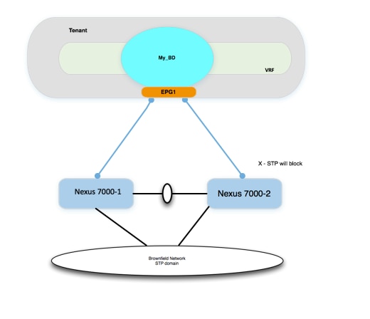
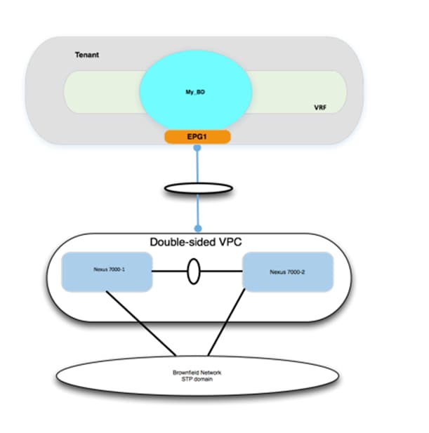
Figure 7: STP and ACI Designs – STP Loop Free with vPC
In the example below, STP BPDUs are flooded inside of the EPG, not at the BD level. However, because there are no physical loops connecting up to the ACI fabric, there is no chance of an STP loop.
ACI Interaction With STP TCNs
Although the ACI fabric control plan doesn’t run STP, it does intercept the STP TCN frame. Why would ACI care about STP TCN frames if it doesn’t run STP? ACI uses the TCNs to flush out MAC address entries, which helps avoiding the “black-holing” of traffic after an STP topology change on the outside network. Upon receiving an STP BPDU TCN frame, the APIC flushes the MAC addresses for the corresponding EPG that experienced the STP topology change. This does have an impact on the choice of how the ACI fabric forwards unknown unicast. By default, the ACI leaf forwards the unknown unicast traffic to a spine proxy for further lookup.
The spine node will drop the packet if the MAC address doesn’t exist in the proxy database. This option is called “Hardware Proxy,” and it is the default option. The other unknown unicast configuration option is “flood mode”, which causes the bridge domain (BD) to operate like a standard switch. When the “Hardware Proxy” option is selected and the fabric detects an STP topology change, the MAC addresses for the EPG are flushed in the fabric. Communication is impacted until the endpoints MAC addresses are learned again.
There are several ways to limit the impact of STP TCNs with ACI. When connecting ACI to external STP domains, use the following best practices:
1. Use vPC or double-sided vPC to connect ACI with STP environments to ensure no Layer 2-looped topology can be created between those networks.
2. Recommend to enable the peer-switch feature with vPC (in the Brownfield STP environment) that will eliminate root-bridge changes.
3. Under the ACI bridge domain (BD) configuration, enable flood mode for Layer 2 unknown unicast packets. This will reduce the traffic disruption during an STP topology change.
ACI With MST
BPDU frames for Per-VLAN Spanning Tree (PVST) and Rapid Per-VLAN Spanning Tree (RPVST) carry a VLAN tag. The ACI leaf can identify which EPG the BPDU should be flooded in based on the VLAN tag in the frame. In MST (802.1s) deployments, however, BPDU frames are sent untagged over the native VLAN. Because of these factors, additional configuration is required in the ACI fabric in order for Multiple Spanning Tree (MST) BPDUs to be properly flooded.
By default, there is no native VLAN configured for ACI. Additionally, the native VLAN is not generally used to carry data traffic. To accept traffic for any VLAN, the VLAN must be provisioned by a statically assigned port and a VLAN to an EPG. As a result, to ensure MST BPDUs are flooded to the desired ports, the user must create a specific EPG to carry those BPDUs. As shown in the following diagram, the mode must be “native” given that the BPDU frame is untagged.
Figure 8: Assign Port to an EPG Using Native Mode
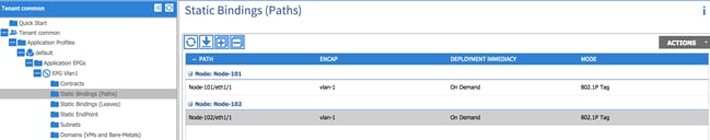
In addition to the configuration tasks previously described, the user must also create a physical domain and associated VLAN pool (which includes VLAN 1 in this example), and the attachable access entity profile to allow VLAN 1 to be used for these ports.
Layer 3 Considerations
MTU
When using routed interfaces, routed subinterfaces, or SVI interfaces for ACI, be aware that the ACI fabric defaults to a system MTU of 9000 for all interfaces (Layer 2 and Layer 3). This means that it is critical to ensure that the MTU configuration on the corresponding external router interfaces matches this value. Failure to do so will lead to suboptimal fragmentation or routing protocol adjacency failures or could lead to packet loss. For example, if devices inside the fabric, that is, VMs, are configured to use jumbo MTUs, and the L3Out is configured for an MTU of 1500, the fabric will drop the packets on egress.
As an example, on external Cisco Nexus 7000 devices, this means you have to configure the following:
· Set the system jumboMTU to 9216 globally:
DCCORE01(config)# system jumbo 9216
· Configure the Layer 2 interfaces (Layer 2 port-channels, Layer 2 trunks, and Layer 2 access ports) to the system jumboMTU value:
DCCORE01(config-if)# mtu 9216
· Configure the Layer 3 interfaces (SVIs, routed sub-interfaces, and Layer 3 routed interfaces) to match the ACI MTU of 9000:
DCCORE01(config-if)# mtu 9000
Note: Enable Jumbo MTUs throughout the datacenter, and use a routing platform (that is, ASR 1000, ASR 9000, and so on) to step down your MTU from jumbo to a standard MTU of 1500. Do not use a switching platform to perform MTU translation.
SVI-Based Interfaces for ACI
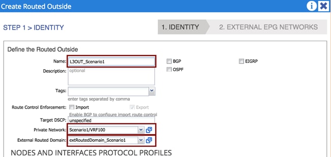
External Routed Domain
When using SVI-based interfaces for external connectivity, it is mandatory that you define and associate an external routed domain to the L3Out connection. This is because incoming and outgoing traffic must be using the specified VLAN tag so that the corresponding SVI interfaces can be enabled. The available VLAN tags are configured in the VLAN pool associated to the External Routed Domain, which will be discussed in more detail in “External Routed Domain” section.
Figure 9: Associate an External Layer 3 Domain to an L3Out Connection
Management Out-of-Band and In-Band
Out-of-Band and In-Band Key Concepts
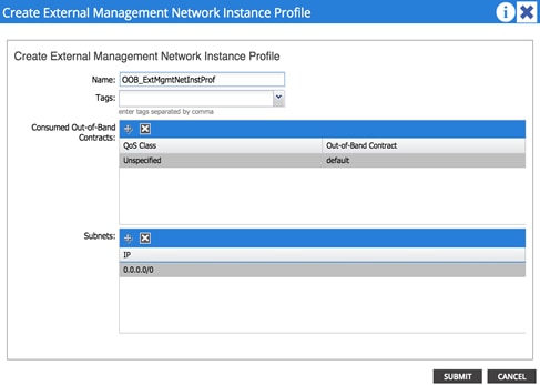
· Contracts are always needed to permit traffic to the out-of-band (OOB) interfaces of the leaf and spine switches. Don’t forget to configure your contract in the “mgmt” tenant.
· Tenant à Tenant mgmt à Node Management EPGs, click Out-Of-Band EPG, and select “default”.
· The default contract acts as a permit ip any.
Figure 10: Create a Contract to Access the OOB Mgmt Network
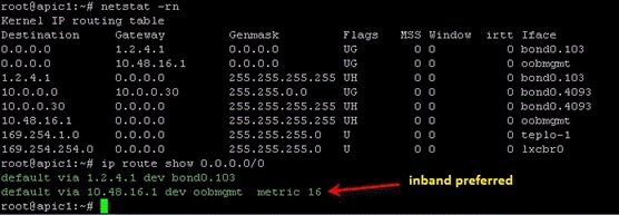
Note: If you install both a default route via OOB and via inband, the inband path is preferred over OOB.
Figure 11: Preferred Inband Default Route
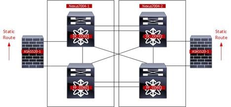
Migration Strategy
The process described in this guide is referred to as “network-centric migration”, and consists of interconnecting the existing Brownfield datacenter network (usually built on STP, vPC or in this case, FabricPath) to a new deployment of ACI, with the goal of migrating workloads from the old environment to the new environment.
In order to accomplish the migration, you must map traditional network concepts (VLANs, IP subnets, VRFs, etc.) to new ACI constructs, like endpoint groups (EPGs), bridge domains (BDs), and private networks (ACI constructs will be discussed later in this document).
The following diagram shows the ACI network-centric migration methodology, which highlights the major steps required for performing the migration of applications from a Brownfield datacenter network to an ACI fabric.
Figure 12: ACI Network Centric Migration Methodology
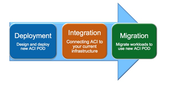
The steps of the ACI network-centric migration are described as follows:
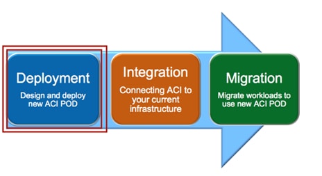
1. Deployment –The first step is the design and deployment of the new ACI POD; it is likely that the size of such a deployment is initially small, with plans to grow it over time. A typical ACI POD consists of at least two spines and two leaf switches, which are managed by a cluster of at least three APIC controllers.
2. Integration – The second step is the integration between the existing DC network infrastructure (usually called the Brownfield network) and the new ACI POD. Layer 2 and Layer 3 connectivity between the two networks is required to allow successful workload migration from the Brownfield network to the new ACI infrastructure.
3. Migration – The final step consists of migrating workloads between the Brownfield network and the ACI POD. It is likely that this application migration process may take several months to complete. During this time, a Layer 2 and Layer 3 interconnect between the Brownfield environment and ACI infrastructure remains in place to allow communication to occur until the migration is complete.
The following sections discuss in great detail those required steps, focusing on specific migration use cases.
· Note: This design guide is the companion document for the “Migrating Existing Networks to Cisco ACI” document.
Connectivity With VLAN to EPG Static Mappings
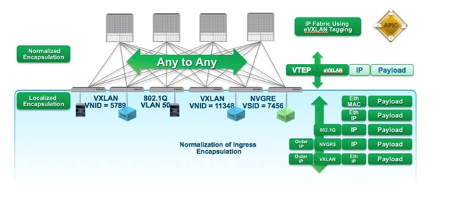
In ACI, VLANs do not exist inside the fabric; they are only defined on the edge ports connecting the virtual or physical endpoints. This means that the VLAN tags are localized on a per-interface basis. This method allows the possibility of establishing intra-IP subnet communication between devices, which are a part of segments identified by different 802.1q encapsulation tags (different VLAN numbers), or even another type of tag altogether, such as VXLAN or NVGRE encapsulation.
The following diagram shows the ACI normalization of ingress encapsulation, which demonstrates the fabric normalization of the port encapsulation.
Figure 13: Fabric Normalization of Port Encapsulation
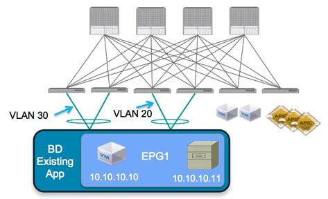
The traditional concept of a VLAN as a Layer 2 broadcast domain is replaced in the ACI fabric with a BD. The BD represents the Layer 2 broadcast domain where endpoints (either virtual or physical) are connected.
To better demonstrate this concept, consider the following diagram, which illustrates that it is possible to associate different VLAN tags (VLAN 20 and 30, in this example), which are configured on different edge ports to the same IP broadcast domain. The result is that endpoint 10.10.10.10 will still be able to communicate with endpoint 10.10.10.11, even though they are attached to different local VLANs.
Figure 14: ACI Local VLAN Significance
To connect the Brownfield network and the ACI fabric via Layer 2, perform the workload migration:
1. Establish a double-sided vPC connection between a pair of ACI border leaf nodes and the two devices representing the boundary between Layer 2/Layer 3 in the Brownfield data center network. Depending on the Layer 2 technology used in the Brownfield network (i.e., STP, vPC or FabricPath), this Layer 2/Layer 3 boundary may be found at the aggregation layer or on a dedicated pair of devices called border leaf nodes. The following diagram shows the Brownfield network connected to the ACI fabric.
The use of dedicated border leaf swithes for Layer 2/Layer 3 connectivity is recommended, but not required. It is worth noting that at the time of writing this document, up to 12K endpoints can be supported on the Brownfield network if they need to communicate at Layer 2 with the ACI fabric. This is because of the size of the hardware table available on a given pair of border leaf nodes to learn the MAC and IP addresses of those endpoints (on a Layer 2 interface). In scenarios where it is required to support a higher number of external endpoints, it is possible to deploy different pairs of border leaf nodes and spread among them the Layer 2 VLANs connecting to the Brownfield network domain. Always ensure that you are within the verified scalability numbers for endpoints, especially when attaching Brownfield environments to ACI. For more information, refer to the following document: http://www.cisco.com/c/en/us/td/docs/switches/datacenter/aci/apic/sw/1-x/verified-scalability/b_Verified_Scalability_Release_1_1_2h.html
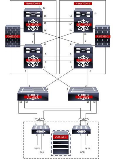
Figure 15: Layer 2 Interconnection between the FP and ACI Networks
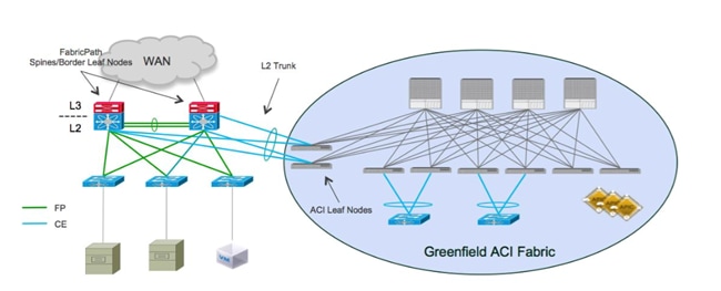
In this example, the Brownfield network is represented by a FabricPath implementation. The FabricPath spine layer not only serves as the Layer 2/Layer 3 boundary for the environment, but will also serve as the connection point to the ACI environment. A double-sided vPC+ connection to a pair of ACI border leaf nodes allows the extension of Layer 2 connectivity between the two network infrastructures without introducing any Layer 2 loop in the topology. This allows all vPC links to actively forward traffic on all paths.
Note: This design would look identical if the Brownfield network was built with STP or vPC as opposed to FabricPath.
2. Associate endpoints connected to VLANs in the Brownfield network to Endpoint Groups (EPGs), which are defined inside of the ACI fabric. As previously mentioned, the recommended approach discussed in this document consists of statically mapping VLAN tags to EPGs on the ACI leaf nodes. When doing so, there are a couple of scenarios to explore, which are discussed in detail in the following two sections.
Scenario 1: Mapping a VLAN to Multiple EPGs
In this scenario, the customer has a single VLAN deployed in the FabricPath network, which supports multiple applications. Due to compliance regulations, the customer intends to segregate the application workloads on VLAN 100 based on application type, but cannot change IP addresses on any of their application servers.
The goal is to migrate the application workloads from the FabricPath environment to the new ACI fabric, where you can take advantage of the security functionalities offered by ACI to logically isolate the application workloads into groups of endpoints, based on application type.
Figure 16: FabricPath to ACI Migration (Scenario 1)
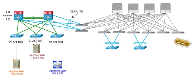
The figure above shows the current application deployment for VLAN 100. All application servers reside in a single FaricPath VLAN.
As shown in the following diagram, the current environment is a FabricPath datacenter, with Cisco Nexus 7000 devices serving as the aggregation/spine devices and providing Layer 2/Layer 3 services. The access layer devices are Cisco Nexus 5648 switches (Layer 2 only). For Scenario 1, there is one routing table configured in the FabricPath environment (which is the default routing table) and one VLAN configured (VLAN 100).
| Figure 17: Current DC Based on FabricPath
|
|
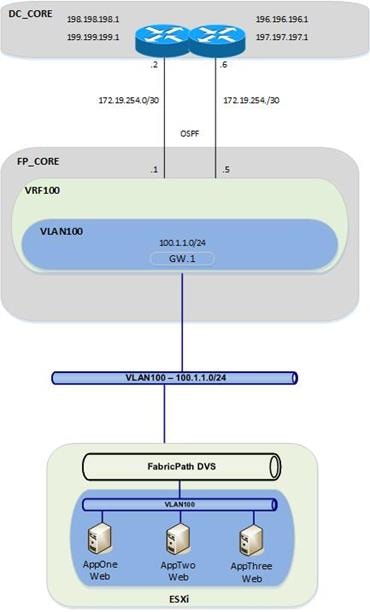
From the FabricPath Core switches, OSPF is running to the Data center core routers (DCCORE01/02).
For the Compute layer, there are two ESXi hosts being managed by vSphere 5.5, with a traditional DVS. For Scenario 1, all three of the VM hosts reside in portgroup VLAN100 on the VMware-managed DVS (Distributed Virtual Switch). Because all three VM hosts reside in the same VLAN, they have full communication to each other, even though they are supporting different applications.
Requirements for New Application Architecture
1. Servers in VLAN 100 are divided into three logical groupings, based upon the application they support. The application grouping is as follows:
a. AppOneWeb
b. AppTwoWeb
c. AppThreeWeb
2. Workloads belonging to the same application can communicate with other servers that support the same application.
3. Servers in one application group cannot communicate with other servers supporting a different application.
4. Communication must be maintained between servers in the legacy FabricPath DC infrastructure and the new ACI DC infrastructure during migration.
5. IP addressing must be maintained unaltered for all servers.
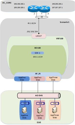
The following diagram shows the desired end state of the ACI fabric. VLAN 100 is subdivided into three endpoint groups: AppOneWeb, AppTwoWeb, and AppThreeWeb, respectively. While these three “groups” will share a common IP subnet, inter-EPG communication is restricted because of the default “white listing” type of policy implemented inside the ACI fabric.
Additionally, you will create a fourth EPG (not shown in the following diagram), called “Outside”, which will be used during the migration between the FabricPath environment and the ACI environment. From an ACI fabric perspective, all the endpoints still connected to the Brownfield network are grouped as part of this outside EPG. Finally, an L3Out connection is utilized to interconnect the ACI fabric to the external Layer 3 network domain.
Figure 18: ACI Fabric at the End of the Implementation
Scenario 2: Mapping VLANs to EPGs (1:1)
In this scenario, the customer has a classic, multitiered application (Web/App/DB), in which each tier of the application is located in its own dedicated VLAN. The customer is performing a network-centric migration of their VLAN into ACI; this implies that each Brownfield VLAN is related to an EPG and a BD in the ACI fabric (VLAN = EPG = BD). By performing static mappings of the VLANs to EPGs, the customer ensures that their workloads, which are connected to the Brownfield FabricPath network, remain a part of the same Layer 2 broadcast domain with the workloads inside of the ACI fabric.
Figure 19: FabricPath to ACI Migration (Scenario 2)
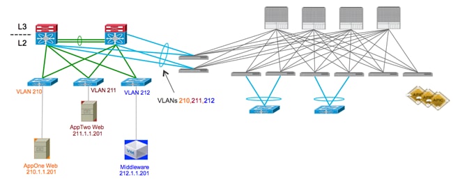
As shown in Figure 17, servers are already deployed into three logical groupings in the FabricPath network, based upon the application (or application tier) they support. The application grouping is as follows:
a. AppOneWeb workloads are part of FP VLAN 210.
b. AppTwoWeb workloads are part of FP VLAN 211.
c. AppThreeWeb workloads are part of FP VLAN 212.
Figure 20: Current DC Based on FabricPath (with FWs)
 |
Those three VLANs are then mapped to different VRF instances (VRF210, VRF211, and VRF212, respectively) to maintain logical isolation between tenants also across the Layer 3 domain.
In this specific scenario, a pair of active/standby firewalls has also been added at the perimeter of the FabricPath network. Each tenant (VRF) connects to a separate FW interface, so that security policies can be enforced to control inter-tenant communication and north-to-south traffic flows between each tenant and the DC Layer 3 core.
For each VRF, a static default route is configured on the FabricPath core switches, pointing to the ASA firewall. The ASA firewall has specific static routes configured to route between FabricPath VRFs, as well as routes to get to devices outside of the data center by routing to the data center core routers (DCCORE01/02). This means that all communication between different VMs has to flow up through the FabricPath environment and out to the firewall before it can talk with another VM of a different VRF.
For the compute layer, there are two ESXi hosts being managed by vSphere 5.5, with a traditional DVS. For Scenario 2, all three of the VM hosts reside in different port groups on the VMware-managed DVS (Distributed Virtual Switch).
Requirements for New Application Architecture
1. Use network-centric deployment mode for ACI (VLAN = EPG = BD).
2. Servers of the same security zone (i.e., VRF) can communicate freely.
3. Server communication between different security zones (i.e., different VRFs) must pass through a stateful firewall for inspection.
4. Communication must be maintained for servers in the legacy FabricPath DC infrastructure and the new ACI DC infrastructure during migration.
5. IP addressing must be maintained for all servers.
Figure 21: Current DC Based on FabricPath

As shown in the following diagram, the end state for the ACI deployment will closely mimic the FabricPath environment. The ACI fabric will have one tenant, three VRFs, and three BD/EPGs that map in a 1:1 fashion to VLANs defined in the FabricPath environment.
Figure 22: ACI Fabric at the End of the Implementation
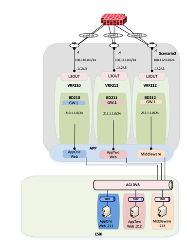
From a compute perspective, the end goal will be to move all of the VMs from the vCenter-managed VDS to an ACI-managed DVS. The VMM integration with the ACI-managed DVS allows for the automatic configuration of EPG-based port groups. This allows VMware administrators to then manage VMNIC setting to control endpoint placement within the ACI fabric.
Infrastructure Deployment Considerations
FabricPath-Enabled Data Center
The FabricPath-enabled data center represents the Brownfield network infrastructure and consists of a traditional FabricPath deployment with a pair of Cisco Nexus 7000 and a pair of Cisco Nexus 5000. The pair of Cisco Nexus 7000 are deployed with a VDC infrastructure to allow them to provide a dual FabricPath core as well as a dual Layer 3 DC core.
Note: For more information about FabricPath and relative deployment best practices, refer to the following documents:
VDC (1) and VDC (2) provide DC core functionality and connect to VDC (3) and VDC (4) representing the FabricPath core.
Figure 23: FabricPath Data Center
Data Center Core
The Data Center core consists of a VDC within each of the Cisco Nexus 7000.
Figure 24: Cisco Nexus 7000 VDCs
| Nexus7K-01 |
|
N7K1# show vdc
Switchwide mode is m1 f1 m1xl f2 m2xl f2e f3
vdc_id vdc_name state mac type lc ------ -------- ----- ---------- --------- ------ 1 N7K1 active 38:ed:18:a2:f1:41 Admin None 2 FP_Core01 active 38:ed:18:a2:f1:42 Ethernet f2e 3 DC_CORE1 active 38:ed:18:a2:f1:43 Ethernet f2e
N7K1#
|
| Nexus7K-02 |
|
N7K2# show vdc
Switchwide mode is m1 f1 m1xl f2 m2xl f2e f3
vdc_id vdc_name state mac type lc ------ -------- ----- ---------- --------- ------ 1 N7K2 active 38:ed:18:a2:f3:c1 Admin None 2 FP_Core02 active 38:ed:18:a2:f3:c2 Ethernet f2e 3 DC_CORE2 active 38:ed:18:a2:f3:c3 Ethernet f2e
N7K2#
|
The DC core is attached to the FabricPath core via a full mesh of 10-G point-to-point connections. Routes are exchanged between the DC core and the FabricPath core using OSPF as routing protocol.
The DC core devices are then interconnected via two 10-G connections and provide the vPC peer-link functionality. This is required since a vPC connection is leveraged to connect to the ACI fabric and establish Layer 3 connectivity.
FabricPath Core
The FabricPath core consists of a VDC within each of the Cisco Nexus 7000.
The FP core devices are connected to the DC core routers via a full mesh of 10-G point-to-point connections. Routes are exchanged between the FP core and the DC core using OSPF.
The FP spines are then interconnected via two 10-G connections that provide the vPC peerlink functionality. The vPCs are then created to connect to the ACI fabric for Layer 2 connectivity.
The FabricPath core VDCs provide the spine functionality and are connected to a pair of Cisco Nexus 5000 leaf switches. The Cisco Nexus 5000 leaf switches are then connected via vPC to the UCS fabric Interconnects (FIs).
Figure 25: Cisco Nexus 7000 FabricPath Configuration
|
FP_Core01# sh run fabricpath
!Command: show running-config fabricpath !Time: Mon Oct 5 07:01:44 2015
version 6.2(12) feature-set fabricpath
vlan 5,10-212,600,610-612 mode fabricpath fabricpath switch-id 201 vpc domain 10 fabricpath switch-id 200
interface port-channel1 switchport mode fabricpath
interface Ethernet3/1 switchport mode fabricpath
interface Ethernet3/2 switchport mode fabricpath
interface Ethernet3/3 switchport mode fabricpath
interface Ethernet3/4 switchport mode fabricpath
interface Ethernet4/1 switchport mode fabricpath
interface Ethernet4/2 switchport mode fabricpath
interface Ethernet4/3 switchport mode fabricpath
interface Ethernet4/4 switchport mode fabricpath fabricpath domain default spf-interval 50 50 50 lsp-gen-interval 50 50 50 root-priority 101
FP_Core01#
|
FP_Core02# show running-config fabricpath
!Command: show running-config fabricpath !Time: Mon Oct 5 07:03:27 2015
version 6.2(12) feature-set fabricpath
vlan 5,10-12,100,210-212,600,610-612 mode fabricpath fabricpath switch-id 202 vpc domain 10 fabricpath switch-id 200
interface port-channel1 switchport mode fabricpath
interface Ethernet3/1 switchport mode fabricpath
interface Ethernet3/2 switchport mode fabricpath
interface Ethernet3/3 switchport mode fabricpath
interface Ethernet3/4 switchport mode fabricpath
interface Ethernet4/1 switchport mode fabricpath
interface Ethernet4/2 switchport mode fabricpath
interface Ethernet4/3 switchport mode fabricpath
interface Ethernet4/4 switchport mode fabricpath fabricpath domain default spf-interval 50 50 50 lsp-gen-interval 50 50 50 root-priority 100
FP_Core02#
|
Network Services
The FabricPath core includes a pair of ASA firewalls for inter-VRF routing within Scenario 2. The FWs are connected to the FP core and to the DC core and are participating in static routing for reachability.
Figure 26: FabricPath Data Center Services
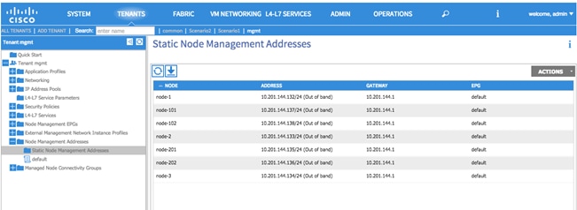
Management
Infrastructure Management
Out-of-band (OOB) management access is used for all devices within the validated topology. This includes the ACI Spine/Leaf switches, the APIC controller cluster, the Cisco Nexus 7000 switches and Cisco Nexus 5600 switches used for FabricPath, the ASA firewalls and the UCS chassis.
Note: Although OOB management was used for the purpose of this migration, in-band management is also a valid design option.
To configure the node management address, log in to the APIC GUI with administrator privileges and follow the path below:
Tenant à [mgmt] à Node Management Addresses
Figure 27: Management - ACI Fabric OOB
Virtual Environment
The virtual environment represents the topology and configuration required to support the distribution of workload in the FabricPath and ACI environments. For the migration, the virtual environment within the FabricPath domain remains the constant while a second virtual environment is deployed to eventually support the workload within the ACI fabric.
Note: Depending on the use case and the requirements, there may not be a requirement for a second virtual environment in the ACI fabric. The use of the second virtual environment within the ACI migration presented in this document is based on the overall assumption that the new data center fabric will also deploy new network and compute devices that would require to be connected to an ACI managed virtual environment.
UCS
The configuration discussed as follows pertains to both the existing FabricPath and the new ACI virtual environments. For each network domain the connected virtual environment consists of a UCSB-Mini with integrated fabric interconnects. Each of the fabric interconnects has a 10-G connection to a pair of FabricPath or ACI leaf nodes. A port channel on each of the fabric interconnects is connected to a vPC on the FabricPath/ACI domains.
Note: Depending on the use case and requirements, there is no ACI requirement for using a Cisco UCSB compute node. Based on the current environment, the migration discussed throughout the document is capable of supporting other compute nodes.
Compute Resources FabricPath Attached
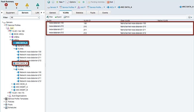
Data vNICs
vNIC DATA_A and vNIC DATA_B have been defined and extended to the ESXi host deployed on the FabricPath-attached compute node. The allowed VLANs include 100, 210, 211 and 212. VLAN 100 as defined in the FabricPath domain supports the VMs associated with Scenario 1 and VLANs 210-212 support the VMs associated with Scenario 2. The VLAN range will be used to create the DVS portgroup mapping for the VM NIC connectivity.
Refer to the following diagram for the vNIC and VLAN usage within the FabricPath-attached UCS chassis for Scenario 1 and Scenario 2.
Figure 28: FabricPath Compute Node Data vNIC
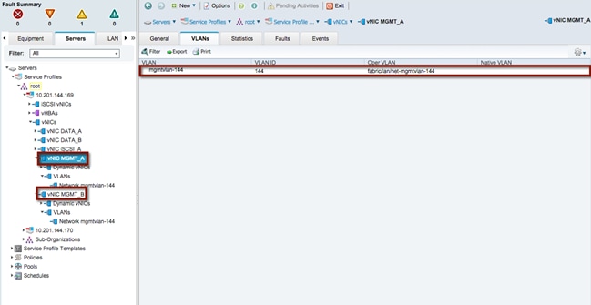
Management vNICs
vNIC MGMT_A and vNIC MGMT_B have been defined and extended to the ESXi hosts deployed on the FabricPath-attached compute node. The allowed VLAN includes VLAN 144 and is defined in the out-of-band (OOB) management infrastructure located within the test environment.
Refer to the following diagram for the vNIC and VLAN usage within the FabricPath-attached UCS chassis associated with the OOB management access.
Figure 29: FabricPath Compute Node Management vNIC
Network Control Policy
In support of the connectivity between the FabricPath domain and the FI, the UCS LAN network control policy is set for CDP Enabled. This allows the FI and the FabricPath network to exchange CDP neighborship messages.
Compute Resources ACI Attached
The compute resources that are connected to the ACI fabric leverage the same vNICs (data and management) previously presented for the compute nodes connected to the FabricPath network. Another pair of Data vNICs must be defined, since the goal is to connect those ESXi hosts to both a vCenter-managed DVS and an ACI-managed DVS. This is discussed in more detail in the “VMware” section.
Data vNICs
As with the FabricPath-attached compute nodes, vNIC DATA_A and vNIC DATA_B have been defined and extended to the ESXi hosts deployed on the ACI-fabric-attached compute nodes. The allowed VLANs include 100, 210, 211 and 212. VLAN 100 supports the VMs associated with Scenario 1 and VLANs 210-212 support the VMs associated with Scenario 2.
Management vNICs
As with the FabricPath-attached compute nodes, vNIC MGMT_A and vNIC MGMT_B have been defined and extended to the ESXi hosts deployed on the ACI-attached compute nodes. The allowed VLAN includes VLAN 144 and is defined in the out-of-band management infrastructure located within the test bed.
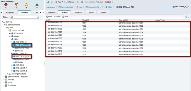
ACI Data vNICs
vNIC DATA_A_ACI and vNIC DATA_B_ACI have been defined and extended to the ESXi host deployed on the ACI-fabric-attached compute node. The allowed VLANs include 1001-1011. VLANs 1001-1010 as defined in the ACI fabric support the VMs associated with Scenario 1 and Scenario 2. The APIC will use a VLAN from the range and associate it to each DVS port group dynamically created as a result of the association of an EPG to the VMM domain. The ACI fabric will hence receive traffic sourced by VMs connected to those port groups tagged with those specific VLAN values.
Figure 30: ACI Fabric Compute Node Data vNIC
Network Control Policy
In support of the connectivity between the ACI domain and the FI, the UCS LAN network control policy is set for CDP enabled. This allows both the FI and the ACI leaf nodes to exchange CDP neighborship messages.
VMware
VMWare ESXi is the validated hypervisor deployed on the compute nodes to facilitate the virtual environments.
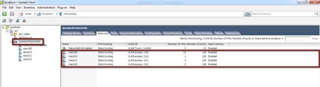
vCenter Managed Distributed Virtual Switch
To support the initial step of the migration strategy, each ESXi host (on both the FP and ACI sides) is connected to a vCenter-managed DVS switch. The DVS switch leverages port groups associated to the FabricPath data VLANs used for Scenario 1 and Scenario 2 respectively: 100, 210, 211 and 212 (see the following diagram).
Figure 31: vCenter Managed DVS
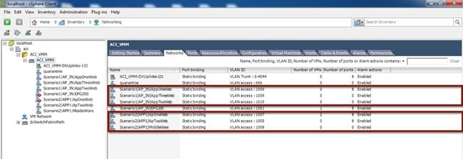
ACI-Managed Distributed Virtual Switch
The final step of the application migration consists of connecting the virtual machines to the ACI-managed DVS that is dynamically created in vCenter after the creation of the VMM Domain (this will be discussed in the “ACI VM Networking” section). The DVS switch will leverage dynamically created port groups associated to ACI internal EPGs and leveraging a set of VLAN tags in the range 1001-1010 (see the following diagram).
Figure 32: ACI-Managed DVS
VMware Uplinks for vCenter-Managed DVS
The data vNICs exposed via the UCS configuration are configured as part of the vCenter-managed DVS uplinks, as shown in the following figure.
Figure 33: VMware Uplinks for vCenter-Managed DVS
|
|
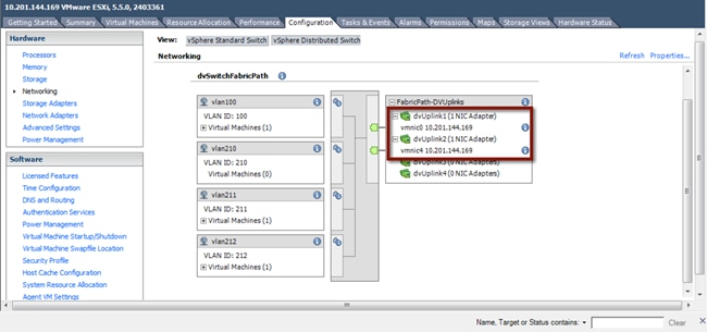
ESXi hosts connected to both the FabricPath and ACI networks are attached to the vSphere-managed DVS, since the first step of the application migration consists of performing a live vMotion of virtual machines across these two ESXi hosts.
VMware Uplinks for ACI-Managed DVS
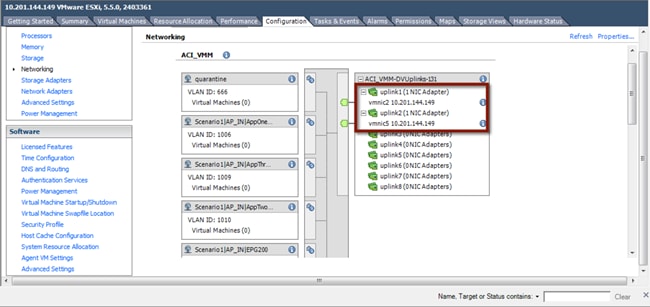
The ACI Data vNICs exposed via the UCS configuration are configured as part of the ACI-managed DVS uplinks, as shown in the following diagram.
Figure 34: VMware Uplinks for ACI-Managed DVS
|
|
| Only the ESXi hosts connected to the ACI fabric have uplinks connected to the ACI-managed DVS. |
CDP
Cisco Discovery Protocol (CDP) is enabled within the vCenter to accommodate the neighborship message exchange from the ESXi host to the ACI fabric. The CDP messages from the VM to the FI and from the FI to the ACI leaf switches are required to properly exchange host details for dynamically created port groups.
Note: ACI has the capability to support user-defined port groups and avoid the requirement for CDP support. VM integration with UCS-B Series and ACI requires specific configurations. Refer to the following for more details: http://www.cisco.com/c/en/us/support/docs/cloud-systems-management/application-policy-infrastructure-controller-apic/118965-config-vmm-aci-ucs-00.html
ACI Infrastructure Deployment
Within this section, you will accomplish the following:
1. Bring the APIC controllers online.
2. Initialize the fabric.
3. Configure the fabric resources for network connectivity.
Each step previously listed is executed once along with the Fabric Configuration section being used in both Scenario (1) and Scenario (2).
The Infrastructure Deployment section is the foundation to the ACI fabric configuration. The APIC Controller section provides the details required to bring the APIC cluster online while the Fabric Initialization section initiates the process for bringing the Spine/Leaf topology online and to configure the infrastructure. Once the APIC and the Spine/Leaf topology is accessible, the Fabric Configuration section provides the necessary details for connecting the ACI fabric to the virtual environment, the FabricPath domain, the data center core and the firewall services layer.
At the Deployment Phase, you are going to configure the ACI fabric and stage it in preparation for integration with the existing FabricPath environment.
Figure 35: Deployment Phase
APIC Controllers
APIC controllers are a set of three servers connected at different points in the ACI fabric. Each APIC server connects to a pair of leaf nodes, with 10-G ports, in active/standby configuration. The 1-G management connections are wired to an out-of-band (OOB) switched network for device access.
In the design discussed herein, the three APICs are each physically connected to the same pair of leaf nodes. With KVM access to each controller, the following table provides the configuration parameters required to initialize the controller nodes. APIC 1 through 3 should be configured sequentially with the appropriate controller details.
Note: In production environments, the recommendation is to connect each APIC node to a different pair of ACI leaf nodes.
Table 1: APIC Controller Initialization
| FabricPathCore |
ACI Fabric |
Notes |
| Fabric Name |
ACI_Fabric |
The fabric name specified must be the same for each controller |
| Number of Controllers |
3 |
Specifies the total number of controllers within the cluster |
| Controller ID |
1 |
Specifies the instance of the controller |
| Controller Name |
apic1/apic2/apic3 |
Specifies the individual controller name |
| TEP Address Pool |
10.0.0.0/16 |
Specifies the address range for VXLAN TEP address pool NOTE: Minimum TEP Address pool is /23. This address range should not overlap with any allocated address space. |
| Infra VLAN ID |
3967 |
Specifies the infrastructure VLAN ID that will be extended to the controllers for infrastructure communications NOTE: 3967 is the recommended Infra VLAN ID because this VLAN is not reserved on any Cisco platform, should it need to be extended outside of the ACI fabric (that is, for extending connectivity to the Cisco AVS virtual switch) |
| Multicast Address Pool |
225.0.0.0/15 |
Specifies the multicast address pool for use within the fabric |
| APIC IP Address/Mask |
10.10.10.10/.11/.12 |
Specifies the management IP address and mask for the specified controller |
| Default Gateway |
10.10.10.1 |
Specifies the default gateway for the controller |
| APIC Password |
******** |
Specifies the administrator password for the fabric |
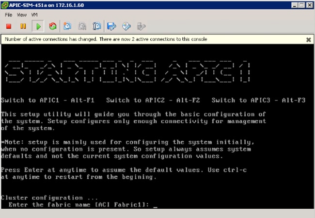
The initial KVM screen output for the controller is noted in the following diagram. After each input, hitting the enter key takes you to the next parameter. Following the last configuration parameter, the output gives you the opportunity to accept the configuration or start the configuration script over.
Note: The Infra VLAN cannot be changed once the startup script has been completed. Changing the Infra VLAN requires initiating the startup script.
Using the parameters in the table above, complete the APIC startup screen for the first APIC then move to the second and third APIC node respectively.
Figure 36: APIC Controller Initialization
Fabric Initialization
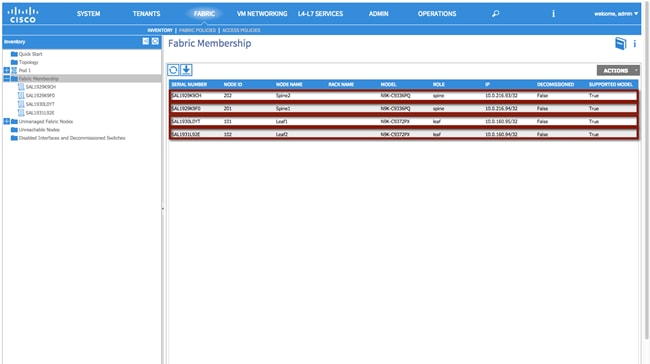
The Fabric Initialization process is the ability to register the given spine/leaf topology. Each node part of the desired infrastructure must be accepted into the topology for connectivity to the overall environment, which makes up the ACI fabric. Once the administrator accepts the node into the fabric and assigns a node ID and name, the APIC then provisions the logical connectivity. Each node is identified within the controller by the platform-specific serial number and will appear in the APIC-generated topology once the configuration is complete.
To initiate fabric Initialization, log in to the APIC GUI with administrator privileges and follow the path below:
Fabric à Inventory à Fabric Membership
Figure 37: Fabric Initialization
Fabric Configuration
This section contains the fabric configuration parameters for resources used throughout the fabric.
Fabric Policies
Route Reflector Policy
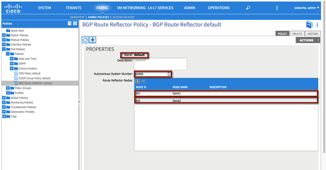
The MP-BGP route reflector policy is used to specify two parameters:
· The AS number assigned to the ACI fabric (65000 in the following example).
· The devices in the ACI fabric deployed as MP-BGP route-reflectors (Spine1 and Spine 2 in the example).
It is worth recalling that MP-BGP is the control plane used inside the ACI fabric to communicate to the ACI leaf nodes external IP prefixes information learned on the border leaf nodes via the L3Out connection.
Fabric à Fabric Policies à Pod Policies à Policies à [BGP Route Reflector default]
Figure 38: Route Reflector Policy
Aside from the GUI representation of the required parameters, the ACI API can also be used to provide access to the configuration and management of the infrastructure. The XML format of the above configuration can be applied utilizing multiple techniques. See the following Cisco APIC REST API User Guide for additional details:
Note: The XML formats required to perform the same configuration steps shown on the APIC GUI will be shown throughout the document, starting with the following BGP RR Policy.
XML 1: Route Reflector Policy
<!—Route Reflector -->
<bgpInstPol descr="" name="default" >
<!—Route Reflector Nodes-->
<bgpRRP descr="" name="">
<bgpRRNodePEp descr="" id="202"/>
<bgpRRNodePEp descr="" id="201"/>
</bgpRRP>
<!—Route Reflector ASN -->
<bgpAsP asn="65000" descr="" name=""/>
</bgpInstPol>
Access Policies
The Access Policy section pertains to the resources required to provide the physical connectivity within the desired topology. The parameters within this section are configured once and referenced in the vPC Scenario (1) and Scenario (2) sections to provide network connectivity.
The following policies are used to create each vPC within the topology:
1. Configure an Attachable Access Entity Profile.
2. Configure an Interface Profile.
3. Configure Interface Policies
a. Configure a Link Level Policy
b. Configure a CDP Policy
c. Configure an LLDP Policy
d. Configure a Port Channel Policy
4. Configure a Switch Profile
5. vPC Policy
The figure below is a representation of the overall fabric resources and how they relate to each other.
Figure 39: Access Policy Model
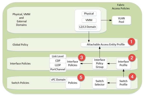
The vPC domain allows for the creation of a user-specified vPC domain to identify the leaf switches participating in the specified vPC while the interface and the switch profiles specify the desired switch and interface polices the vPC domain will be created within.
Each vPC configuration (Interface Policy Group) references physical attributes such as link/speed and port channel behavior policies. The individual interface policies are defined and referenced for each subsequent vPC configuration.
Note: The use of the Quick Start guide is not used in order to demonstrate the object relationship for the configuration parameters. Additionally, while Quick Start menus can change from version to version, the method of configuration displayed in this whitepaper will remain valid.
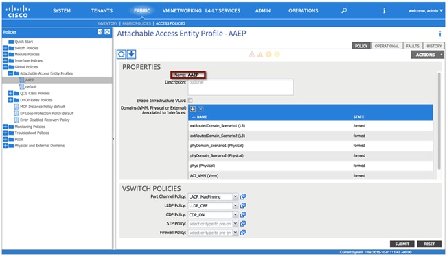
Attachable Access Entity Profile
The Attachable Access Entity Profile provides a template for attachment point between the switch and interface profiles and the fabric resources such as the VLAN pool. The AEP can be considered the ‘glue’ between the defined physical, virtual or Layer 2 / Layer 3 domains and the fabric interfaces (logical or physical), essentially allowing to specify what VLAN tags can be used on those interfaces.
Note: Although a single AEP is used to support both scenarios, multiple AEPs can be deployed providing further granularity in defining connectivity.
To configure an attachable access entity profile, login to the APIC GUI with administrator privileges and follow the path below:
Fabric à Access Policies à Global Policies à Attachable Access Entity Profiles à [AAEP]
Figure 40: Attachable Access Entity Profile
XML 2: Attachable Access Entity Profile
<!—Attachable Access Entity Profile -->
<infraAttEntityP descr="" name="AAEP" >
</infraAttEntityP>
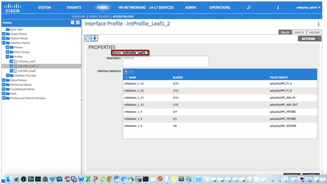
Interface Profile
The Interface Profile enables you to define a set of “interface selectors” each specifying a block of physical interfaces. Each selector uses the properties identified under the corresponding Interface Policy Group, as shown in following diagram. The policy names used in the following example reflect the policy type name and the node(s). A single interface profile will be used for each switch and switch combination used in the topology.
Note: Depending on the use case, multiple combinations of interface profiles can be deployed.
To configure an interface profile, log in to the APIC GUI with administrator privileges and follow the path below:
Fabric à Access Policies à Interface Policies à Profiles à [intProfile_Leaf1_2]
Figure 41: Interface Profile
XML 3: Interface Profile
<!—Interface Profile -->
<infraAccPortP descr="" name="intProfile_Leaf1_2"/>
</infraAccPortP>
Repeat the process for the remaining interface profiles:
Fabric à Access Policies à Interface Policies à Profiles à [intProfile_Leaf1]
Fabric à Access Policies à Interface Policies à Profiles à [intProfile_Leaf2]
The ACI Interface Policies specify interface properties for fabric connectivity. The interface policies are used for all physical connections and are reflective of the physical device connected.
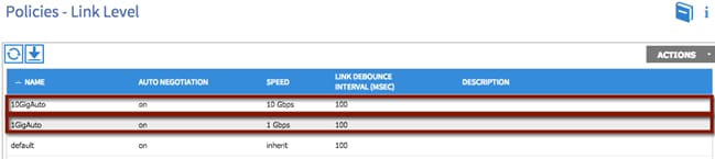
Link Level Policy
The link level policy specifies the Layer 1 parameters of host-facing ports. The policy contains the interface-specific details such as auto-negotiation, speed, and debounce interval. The policy names used as follows reflect the speed and negotiation abilities.
To configure a link level policy, log in to the APIC GUI with administrator privileges and follow the path below:
Fabric à Access Policies à Interface Policies à Policies à Link Level
Figure 42: Interface Policy – Link Level Policy
XML 4: Interface Policy - Link Level Policy
<!—1 GIG Auto Policy -->
<fabricHIfPol autoNeg="on" descr="" linkDebounce="100" name="1GigAuto" speed="1G"/>
<!—10 GIG Auto Policy -->
<fabricHIfPol autoNeg="on" descr="" linkDebounce="100" name="10GigAuto" speed="10G"/>
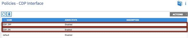
CDP Policy
The CDP interface policy is primarily used to obtain protocol addresses of neighboring devices and discover the platform of those devices. The policy names used as follows reflect the policy type and admin state.
To configure a CDP policy, log in to the APIC GUI with administrator privileges and follow the path below:
Fabric à Access Policies à Interface Policies à Policies à CDP Interface
Figure 43: Interface Policy – CDP Policy
XML 5: Interface Policy - CDP Policy
<!—CDP Off Policy -->
<cdpIfPol adminSt="disabled" descr="" name="CDP_OFF" />
<!—CDP On Policy -->
<cdpIfPol adminSt="enabled" descr="" name="CDP_ON" />
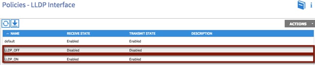
LLDP Interface
The LLDP interface policy defines a common configuration that applies to one or more LLDP interfaces. LLDP uses the logical link control (LLC) services to transmit and receive information to and from other LLDP agents. The policy names used as follows reflect the policy type and admin state.
To configure an LLDP policy, login to the APIC GUI with administrator privileges and follow the path below:
Fabric à Access Policies à Interface Policies à Policies à LLDP Interface
Figure 44: Interface Policy – LLDP Policy
XML 6: Interface Policy - LLDP Policy
<!—LLDP Off Policy -->
<lldpIfPol adminRxSt="disabled" adminTxSt="disabled" descr="" name="LLDP_OFF" />
<!—LLDP On Policy -->
<lldpIfPol adminRxSt="enabled" adminTxSt="enabled" descr="" name="LLDP_ON" />
Port Channel Policies
The port channel policy enables you to bundle several physical ports together to form a single port channel. LACP enables a node to negotiate an automatic bundling of links by sending LACP packets to the peer node. The policy names used as follows reflect the policy type name and mode.
To configure a port channel policy, log in to the APIC GUI with administrator privileges and follow the path below:
Fabric à Access Policies à Interface Policies à Policies à Port Channel Policies
Figure 45: Interface Policy – Port Channel Policy
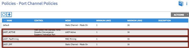
XML 7: Interface Policy - Channel Policy
<!—Port Channel LACP Active Policy -->
<lacpLagPol ctrl="fast-sel-hot-stdby,graceful-conv,susp-individual" descr="" dn="uni/infra/lacplagp-LACP_ACTIVE" maxLinks="16" minLinks="1" mode="active" name="LACP_ACTIVE" />
<!—Port Channel LACP MacPinning Policy -->
<lacpLagPol ctrl="fast-sel-hot-stdby,graceful-conv,susp-individual" descr="" dn="uni/infra/lacplagp-LACP_MacPinning" maxLinks="16" minLinks="1" mode="mac-pin" name="LACP_MacPinning" />
<!—Port Channel LACP Off Policy -->
<lacpLagPol ctrl="fast-sel-hot-stdby,graceful-conv,susp-individual" descr="" dn="uni/infra/lacplagp-LACP_OFF" maxLinks="16" minLinks="1" mode="off" name="LACP_OFF" />
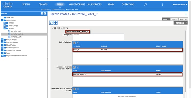
Switch Profile
The switch profile identifies the leaf nodes that are provisioned to support the environment. The switch profile name swProfile_Leaf1_2 specifies a switch selector designator Leaf1_2 identifying nodes 101 and 102. Also, the previously defined interface profiles are also associated to the switch profiles, as shown in the following diagram.
Note: The switch profile configuration must be updated following the completion of each interface profile.
To configure a switch profile, log in to the APIC GUI with administrator privileges and follow the path below:
Fabric à Access Policies à Switch Policies à Switch Profile à [swProfile_Leaf1_2]
Figure 46: Switch Profile
XML 8: Switch Profile
<infraNodeP descr="" name="swProfile_Leaf1_2" >
<!—Switch Profile Leaf Selector -->
<infraLeafS descr="" name="Leaf1_2" type="range">
<infraNodeBlk descr="" from_="101" name="29a1f174834b2ea7" to_="102"/>
</infraLeafS>
<!—Associated Interface Profile -->
<infraRsAccPortP tDn="uni/infra/accportprof-intProfile_Leaf1_2"/>
</infraNodeP>
Repeat the process for the remaining switch profiles:
Fabric à Access Policies à Switch Policies à Switch Profile à [swProfile_Leaf1]
Fabric à Access Policies à Switch Policies à Switch Profile à [swProfile_Leaf2]
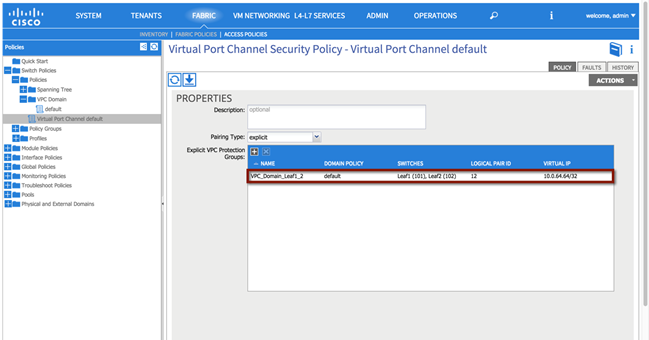
Virtual Port Channel (vPC) Domain
The vPC domain identifies the leaf nodes that define a virtual port channel. Within the vPC configuration, a VPC explicit protection group represents a vPC domain (a protection group). You can explicitly configure member nodes of the group using a fabric policy node endpoint. The explicit vPC protection group name used in Scenario 1 is ‘VPC_Domain_Leaf1_2’ along with the logical pair ID number ‘12’.
Note: Depending on the use case, multiple vPC domains may need to be created to support the topology.
To configure a vPC domain, login to the APIC GUI with administrator privileges and follow the path below:
Fabric à Access Policies à Switch Policies à Switch Profile à [swProfile_Leaf1_2]
Figure 47: vPC Domain
XML 9: vPC Domain
<!—vPC Domain -->
<fabricProtPol descr="" name="default" pairT="explicit">
<!—vPC ID and Name-->
<fabricExplicitGEp id="12" name="VPC_Domain_Leaf1_2">
<fabricRsVpcInstPol tnVpcInstPolName="default"/>
<!—Node Selection -->
<fabricNodePEp descr="" id="101" name=""/>
<fabricNodePEp descr="" id="102" name=""/>
</fabricExplicitGEp>
</fabricProtPol>
Creation of Virtual Port Channels (vPCs)
This section provides the steps required to support the vPC configuration on the pair of ACI leaf switches used in the validated topology. Multiple vPCs are used to support the physical connectivity of external devices to the ACI fabric, as for example the Cisco Nexus 7000 switches (FabricPath and DC core devices) for Layer 2 and Layer 3 connectivity, the ASAs for firewall services and the UCS for virtual hosts.
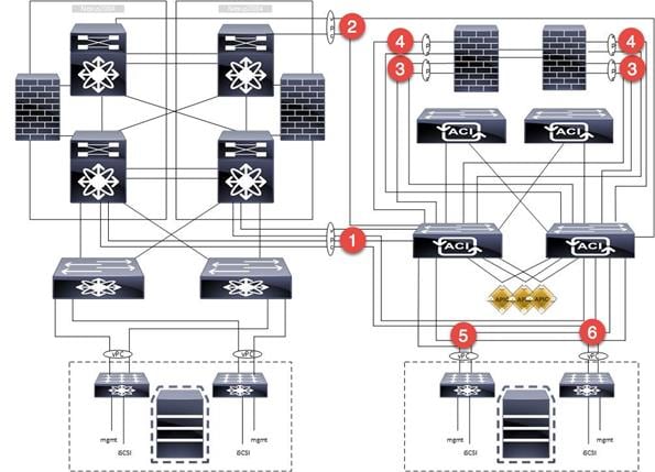
The following network diagram highlights all the vPC connections used for the different migration scenarios:
1. The vPC identified with the number 1 is used for the Layer 2 connectivity between the ACI fabric and the FabricPath core and will be named VPC_FPCORE.
2. vPC 2 is used for layer 3 connectivity between the ACI fabric and the DC core (VPC_DCCORE).
3. vPC 3 is used for the connectivity between the ACI fabric and the ASA inside interface. Notice how two separate vPC connections are used from the ACI fabric, one to connect to the Active FW node and the other to connect to the Standby node (VPC_ASA_IN_1 and VPC_ASA_IN_2). This has some important implications for the configuration of the L3Out connections between the ACI VRFs and the ASA FWs, as discussed in more detail in the “External Routed Networks” section part of the migration Scenario 2.
4. vPC 4 is used for the connectivity between the ACI fabric and the ASA outside interface. As discussed above, two vPC logical connections are used also in this case, one to each ASA FW node (VPC_ASA_OUT_1 and VPC_ASA_OUT_2).
5. vPC 5 is used for the UCS connectivity between the ACI fabric and Fabric Interconnect A (VPC_FI_A).
6. vPC 6 is used for the UCS connectivity between the ACI fabric and Fabric Interconnect B (VPC_FI_B).
Figure 48: vPC Connections
Some important considerations that relate to the creation of those vPC logical connections:
· Depending on the topology and requirements, other valid configurations may be used to establish Layer 3 connectivity between the Brownfield and ACI environments (routed interfaces or routed sub-interfaces in lieu of SVI connectivity over vPC). The design suggested in this document consists in creating a logical vPC connection and static routing. This provides the advantage that a link failure scenario would be recovered at the Layer 2 level (that is, re-hashing of traffic flows across the remaining physical links of the vPC).
· The reason you didn’t just use the same Layer 2 vPC1 also for establishing Layer 3 connectivity between the FP and the ACI networks (instead of the separate vPC2) is because traditionally, during migrations, the idea is to migrate off the equipment that is Layer 2 attached, and then retire it, shut it down, or repurpose it. It was important to demonstrate that the Layer 3 DC routers (DCCORE01/02) would be used even after migration from the FabricPath FP_CORE01/02 devices was completed.
· Although multiple vPCs on the ASA were used (a vPC for the inside interface and a separate vPC for the outside interface), a single vPC could have also been deployed to support the same topology. The use case and connectivity requirements should define the overall connectivity strategy.
The following sections highlight the different configuration steps required for the creation of a vPC.
Note: The vPC configuration discussed in the following sections is relative to the creation of VPC_FPCORE (for Layer 2 connectivity between the FP and the ACI networks). A pretty much identical procedure can be followed for the creation of the other vPC connections (not covered in this document).
vPC1: FabricPath Core to ACI Leaf Nodes
The following section describes the procedure for creating in APIC the vPC logical connection used for Layer 2 communication between the FabricPath and the ACI networks.
The Cisco Nexus 7000 FP spines will be connected to the ACI leaf switches using full-meshed 10-G interfaces for redundancy and to carry data traffic for different VLANs used for the migration scenarios. The 2x10G interfaces will be directly connected between two Cisco Nexus 7000 switches for high availability.
The following table provides the physical interface designation for the Cisco Nexus 7000 and the ACI leaf connectivity.
Table 2: Layer 2 Physical Connectivity
| Fabric Path Core |
ACI Fabric |
Speed |
| FP_CORE1_3/10 |
Leaf1_1/4 |
10GIG |
| FP_CORE1_3/11 |
Leaf2_1/4 |
10GIG |
| FP_CORE2_3/11 |
Leaf1_1/5 |
10GIG |
| FP_CORE2_3/11 |
Leaf2_1/5 |
10GIG |
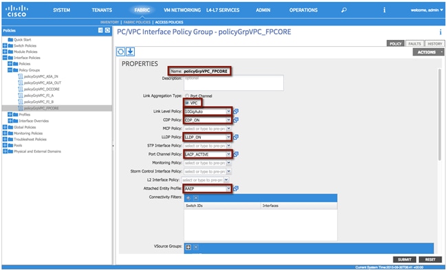
vPC1 Interface Policy Group
The Interface Policy Group enables you to specify the interface characteristics and define the behavior for selected ports. Within the Interface Policy Group, interface parameters such as the link properties (Link Level Policy) and Port Channel capabilities are defined. The policy names used as follows reflect the policy type name along with the interface type and location within the topology.
To configure an interface policy group, log in to the APIC GUI with administrator privileges and follow the path below:
Fabric à Access Policies à Interface Policies à Policy Groups à [policyGrpVPC_FPCORE]
Table 3: Layer 2 vPC Interface Policy Group
| Interface Poicy Group |
Configuration |
| Name |
policyGrpVPC_FPCORE |
| Link Aggregation Type |
VPC |
| Link Level Policy |
10GIGAuto |
| CDP_Policy |
CDP_ON |
| LLDP_Policy |
LLDP_ON |
| Port Channel Policy |
LACP_ACTIVE |
| Attachable Entity Profile |
AAEP |
Figure 49: Layer 2 vPC Interface Policy Group
XML 10: vPC Interface Policy Group
<infraAccBndlGrp descr="" dn="uni/infra/funcprof/accbundle-policyGrpVPC_FPCORE" lagT="node" name="policyGrpVPC_FPCORE" >
<infraRsMonIfInfraPol tnMonInfraPolName=""/>
<!—LLDP Policy Selection -->
<infraRsLldpIfPol tnLldpIfPolName="LLDP_ON"/>
<infraRsStpIfPol tnStpIfPolName=""/>
<!—LLDP Policy Selection -->
<infraRsCdpIfPol tnCdpIfPolName="CDP_ON"/>
<infraRsL2IfPol tnL2IfPolName=""/>
<!— Attachable Entity Profile Selection -->
<infraRsAttEntP tDn="uni/infra/attentp-AAEP"/>
<infraRsMcpIfPol tnMcpIfPolName=""/>
<!—Port Channel Policy Selection -->
<infraRsLacpPol tnLacpLagPolName="LACP_ACTIVE"/>
<infraRsStormctrlIfPol tnStormctrlIfPolName=""/>
<!—Link Level Policy Selection -->
<infraRsHIfPol tnFabricHIfPolName="10GigAuto"/>
</infraAccBndlGrp>
Note: The interface policies selected are the ones previously created in the “Interface Policies” section.
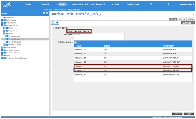
vPC1 Interface Profile
The Interface Profile enables you to define the specific interfaces that use the properties identified under the Interface Policy Group. Within the Interface Profile, each physical interface is identified and added. The policy names used as follows reflect the policy type name and the node(s).
To configure an Interface Profile, log in to the APIC GUI with administrator privileges and follow the path below:
Fabric à Access Policies à Interface Policies à Profiles à [intProfile_Leaf1_2]
Table 4: Layer 2 vPC Interface Profile
| Interface Profile |
Configuration |
| Interface Selector |
intSelector_1_4 |
| Interface Selector |
intSelector_1_5 |
Note: Object names, such as the Interface Selector name, cannot be modified once implemented. This may present an operational challenge if the specific interfaces wanted to be re-used later on in the future. Because of this fact, separate interface selectors were created for each and every interface in use. This ensures that the interface selectors can be reused in the future, if needed, with no impact. Careful consideration should be exercised when planning object naming.
Figure 50: Layer 2 vPC Interface Profile
XML 11: Layer 2 vPC Interface Profile
<infraAccPortP descr="" name="intProfile_Leaf1_2" >
<!—Interface Selector -->
<infraHPortS descr="" name="intSelector_1_5" type="range">
<infraRsAccBaseGrp fexId="101" tDn="uni/infra/funcprof/accbundle-policyGrpVPC_FPCORE"/>
<!—Port Selector -->
<infraPortBlk descr="" fromCard="1" fromPort="5" name="block2" toCard="1" toPort="5"/>
<!—Interface Selector -->
</infraHPortS>
<infraHPortS descr="" name="intSelector_1_4" type="range">
<infraRsAccBaseGrp fexId="101" tDn="uni/infra/funcprof/accbundle-policyGrpVPC_FPCORE"/>
<!—Port Selector -->
<infraPortBlk descr="" fromCard="1" fromPort="4" name="block2" toCard="1" toPort="4"/>
</infraHPortS>
</infraAccPortP>
ACI VM Networking
VMM integration allows a manager such as VMware vCenter to be linked to ACI so that policies can be made available for virtual machines hosted within the VMM domain. Once the APIC and a vCenter servers are linked together (via communication over an OOB network) with the creation of a VMM domain, the following actions take place:
· A Distributed Virtual Switch (DVS) managed by APIC is created and made available to all the ESXi hosts managed by the vCenter server.
· Every time an EPG is created in APIC and bound to the VMM domain, a corresponding port group is dynamically created in vCenter for the previously described DVS. Virtual machines (VMs) can then be connected to that port group and this allows the ACI fabric to classify them as part of the defined EPG.
The following sections described the various steps required for the creation of the VMM Domain.
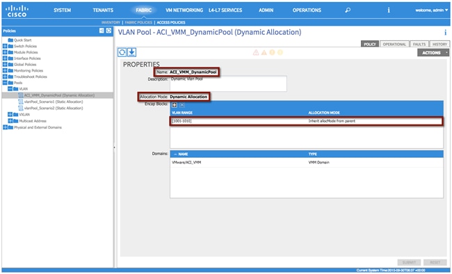
Dynamic VLAN Pool
A Dynamic VLAN pool is managed internally by the APIC to allocate VLANs to the dynamically created port groups (associated to the EPGs) that are made available on the APIC-managed DVS. In the following example, a Dynamic Pool 1000-1010 is created and will be used for the migration scenarios discussed in later sections.
Note: A VMM domain can be associated with only one dynamic VLAN pool.
Table 5: VM Networking – Dynamic VLAN Pool
| VM Networking |
VLAN Pool |
Description |
| Name |
ACI_VMM_DynamicPool |
- |
| Allocation Mode |
Dynamic Allocation |
- |
| Encap Block |
1000-1010 |
VM Portgroup VLAN Pool |
To configure a dynamic VLAN pool, login to the APIC GUI with administrator privileges and follow the path below:
Fabric à Access Policies à Pools à VLAN à [ACI_VMM_DynamicPool]
Figure 51: VM Networking – Dynamic VLAN Pool
XML 12: VM Networking – Dynamic VLAN Pool
<fvnsVlanInstP allocMode="dynamic" descr="Dynamic Vlan Pool" name="ACI_VMM_DynamicPool">
<!—VLAN Pool -->
<fvnsEncapBlk allocMode="inherit" from="vlan-1001" name="" to="vlan-1010"/>
</fvnsVlanInstP>
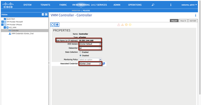
Creation of the VMM Domain
VMM domains contain VM controllers such as VMware vCenter or Microsoft System Center Virtual Machine Manager (SCVMM) and the credential(s) required for the ACI API to interact with the VM controller. A VMM domain enables VM mobility within the domain but not across domains.
To configure a VMM domain, the first step is defining the VM Provider (Microsoft or VMware options are available at the time of writing of this document). In order to do that, log in to the APIC GUI with administrator privileges and follow the path below:
Fabric à VM Networking à Policies à VM Provider VMware à [ACI_VMM] à Controller
Figure 52: VM Networking – Provider VMware
XML 13: VM Networking – Provider VMware
<vmmDomP enfPref="hw" mcastAddr="0.0.0.0" mode="default" name="ACI_VMM">
<vmmRsDefaultStpIfPol tnStpIfPolName="default"/>
<vmmRsDefaultFwPol tnNwsFwPolName="default"/>
<vmmRsDefaultLldpIfPol tnLldpIfPolName="default"/>
<!—vCenter IP -->
<vmmCtrlrP dvsVersion="unmanaged" hostOrIp="10.201.144.160" inventoryTrigSt="untriggered" name="controller" port="0" rootContName="aci" scope="vm" statsMode="disabled">
<!—vCenter Credentials -->
<vmmRsAcc tDn="uni/vmmp-VMware/dom-ACI_VMM/usracc-Creds"/>
</vmmCtrlrP>
<!—Dynamic VLAN Pool -->
<infraRsVlanNs tDn="uni/infra/vlanns-[ACI_VMM_DynamicPool]-dynamic"/>
<vmmRsDefaultCdpIfPol tnCdpIfPolName="default"/>
<vmmRsDefaultLacpLagPol tnLacpLagPolName="default"/>
<vmmRsDefaultL2InstPol tnL2InstPolName="default"/>
<vmmUsrAccP descr="" name="Creds" usr="root"/>
</vmmDomP>
As shown in following figure, the following parameters must be specified to successfully create a VMM domain:
· Host name (or IP Address): this is the DNS name or IP address of the vCenter server the APIC should be paired with.
· DVS version: specifies the version of the APIC-managed DVS that is created as a result of the pairing between APIC and vCenter.
· Datacenter: specifies the set of compute resources that will be part of the VMM Domain. The same vCenter server may define different logical data centers and a separate VMM domain can be created associating the APIC with each data center object defined in vCenter. It is also important to ensure that the data center name used in vCenter exactly matches the “Datacenter” configuration section in the VMM Controller policy window.
Figure 53: VMM Integration
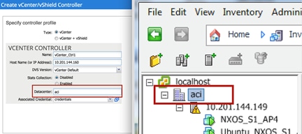
· Associated Credentials: those are the credentials required to connect to the vCenter server.
Associate the VMM Domain to the Attachable Entity Profile
As previously mentioned, the Attachable Access Entity Profile provides a template for attachment point between the switch and interface profiles and the fabric resources such as the VLAN pool. In order to be able to use the VLANs part of the Dynamic Pool (1000-1010) for connectivity to the various port groups defined in the APIC-managed DVS, it is first required to associate the just created VMM domain to the AEP previously created in the “Access Policies” section.
Note: Although a single Attachable Access Entity Profile was deployed to support the fabric path migration (for both physical and virtual domains for both Scenarios 1 and 2), individual use cases and connectivity requirements may dictate the use of multiple AAEPs. One such use case is an overlap of VLAN resources amongst tenants.
To associate the VMM Domain with the Attachable Entity Profile, log in to the APIC GUI with administrator privileges and follow the path below:
Fabric à Access Policies à Global Policies à Attachable Access Entity Profiles à [AAEP]
Figure 54: VM Networking – Attachable Access Entity Profile
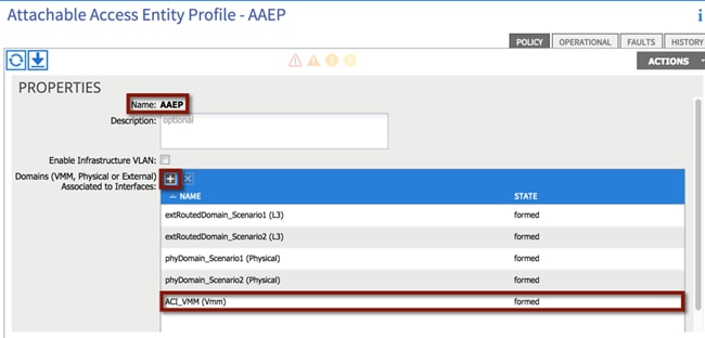
XML 14: VM Networking – Attachable Access Entity Profile
<infraAttEntityP name="AAEP" >
<!—VMM Domain Association -->
<infraRsDomP tDn="uni/vmmp-VMware/dom-ACI_VMM"/>
</infraAttEntityP>
vSwitch Policy
To support connectivity from the ACI fabric to vCenter VMware a combination of CDP/LLDP are used to exchange host connectivity details. To enable the APIC-created DVS with the supported communication protocol, a vSwitch with CDP enabled and LLDP disabled is created and attached to the AEP, Attachable Access Entity Profile.
Note: VM integration with UCS-B Series and ACI requires specific configurations. Refer to the following document for more information:
To configure a VMM vSwitch Policy, log in to the APIC GUI with administrator privileges and follow the path below:
Fabric à Access Policies à Global Policies à Attachable Access Entity Profile à [AAEP]
Figure 55: VM Networking – vSwitch Policy

XML 15: VM Networking – vSwitch Policy
<infraAttEntityP name="AAEP" >
<!—vSwitch Policy -->
<infraAttPolicyGroup descr="" name="">
<infraRsOverrideCdpIfPol tnCdpIfPolName="CDP_ON"/>
<infraRsOverrideLacpPol tnLacpLagPolName="LACP_MacPinning"/>
<infraRsOverrideLldpIfPol tnLldpIfPolName="LLDP_OFF"/>
</infraAttPolicyGroup>
</infraAttEntityP>
Migration Scenario 1
Now that the work has been done in the “Infrastructure Deployment Considerations” section (that is all the physical interfaces, vPC domain, BGP RR, VM Networking integration common to all the migration scenarios have been configured), the specific migration scenario configurations can start. These include fabric access policy configuration (specific for Migration Scenario 1) and tenant configuration.
Note: A single tenant configuration is shown as part of the Migration Scenario 1, but the same considerations remain valid and can be replicated in a multitenant environment.
1. Fabric Access Policy Configuration
a. Static VLAN Pool
b. Physical Domain
c. External Routed Domain that is used to create the L3Out connection between the ACI fabric and the DC core routers (DCCORE01/02 routers)
2. Tenant Configuration
a. Tenant creation (named “Scenario 1”)
b. Private Network (that is, VRF100; this maps to the default VRF in the FabricPath domain)
c. Bridge Domain (that is, BD100; this will map to VLAN 100 in the FabricPath domain)
d. Security Contracts, where applicable
i. L3OUT contract
ii. Outside contract
e. Connectivity (via an L3Out to DCCORE01/02)
f. Application Profile and EPGs (i.e., Application Profile AP_IN and AP_OUT)
i. EPG Outside
ii. EPG AppOneWeb
iii. EPG AppTwoWeb
iv. EPG AppThreeWeb
Figure 56: Scenario 1 ACI Design
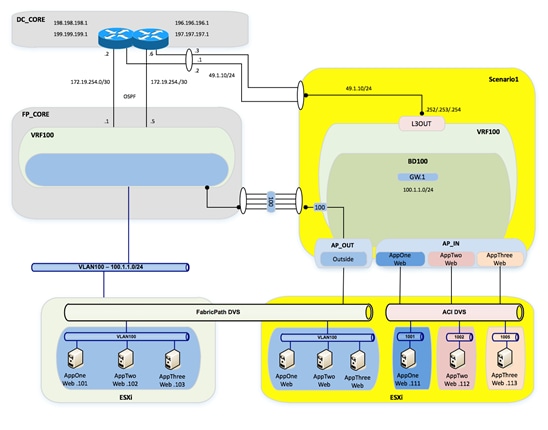
Fabric Access Policy Configuration
Static VLAN Pool
A static VLAN pool (vlanPool_Scenario1) needs to be created for Scenario 1with the following encap blocks:
· “L3OUT” Encap Block: defines the VLAN tag that is going to be used on the L3Out to establish Layer 3 connectivity between the FP and the ACI networks. As already discussed, the design choice was to create a vPC logical connection with static routing for this purpose, so VLAN 49 is used to establish Layer 3 communication between SVIs defined on the ACI Border Leaf nodes and corresponding SVIs defined on the DC Core devices.
· “Layer2” Encap Block: defines the set of VLANs used to establish Layer 2 connectivity between the FP and the ACI networks. Only VLAN 100 is required for migration Scenario 1.
Table 6: Scenario 1 Static VLAN Pools
| VLAN Pool |
Configuration |
Description |
| Name |
vlanPool_Scenario1 |
- |
| Allocation Mode |
Static Allocation |
- |
| Encap Block |
49 |
L3OUT |
| - |
100 |
Layer 2 |
To configure the static VLAN pool, log in to the APIC GUI with administrator privileges and follow the path below:
Fabric à Access Policies à Pools à VLAN à [vlanPool_Scenario1]
Figure 57: Scenario 1 Static VLAN Pool
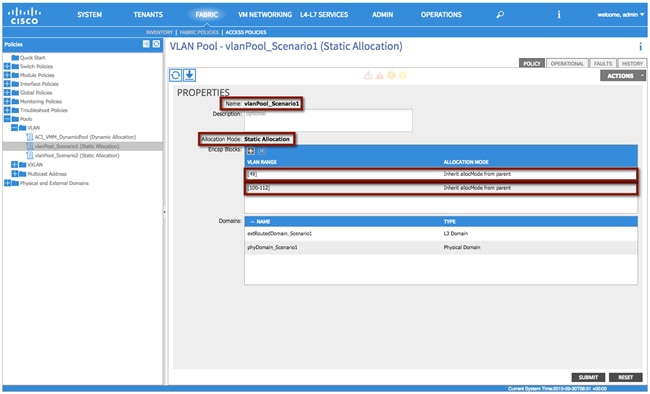
XML 16: Scenario 1 Static VLAN Pool
<fvnsVlanInstP allocMode="static" name="vlanPool_Scenario1" >
<!—VLAN Pools -->
<fvnsEncapBlk allocMode="inherit" descr="" from="vlan-49" name="" to="vlan-49"/>
<fvnsEncapBlk allocMode="inherit" descr="" from="vlan-100" name="" to="vlan-112"/>
</fvnsVlanInstP>
Physical Domain
Differently from the VMM domain previously discussed, physical domains are usually specifically defined for each given tenant because in most deployments, a physical server belongs to one tenant. In the specific case of migration Scenario 1, the physical domain is defined not to connect physical servers but to allow connectivity from the ACI fabric to the VMs that have not yet been migrated and are still connected to the FP network, as well to VMs that have been migrated to the ACI fabric but are initially connected to the vCenter-managed VDS. Since a static EPG-VLAN mapping is performed to allow Layer 2 connectivity to those VMs, they can be considered as “physical resources” from an ACI fabric perspective, hence it is required to define a physical domain to be able to specify the VLANs to be used to connect to them.
Note: In multitenant deployments, a separate physical domain will likely be created for each tenant. This allows to granularly manage resources associated with each tenant.
See the following table for the configuration details:
Table 7: Scenario 1 Physical Domain
| Physical Domain |
Configuration |
| Name |
phyDomain_Scenario1 |
| VLAN Pool |
vlanPool_Scenario1 |
To configure the physical domain, log in to the APIC GUI with administrator privileges and follow the path below:
Fabric à Access Policies à Physical and External Domains à Physical Domains à [phyDomain_Scenario1]
Figure 58: Scenario 1 Physical Domain
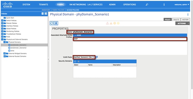
XML 17: Scenario 1 Physical Domain
<physDomP name="phyDomain_Scenario1" >
<!—VLAN Pool association -->
<infraRsVlanNs tDn="uni/infra/vlanns-[vlanPool_Scenario1]-static"/>
</physDomP>
As shown above, the physical domain is both associated with the AEP and with the static VLAN pool previously defined.
External Routed Domain
As previously mentioned, a VLAN (or in general a set of VLANs) is required for establishing Layer 3 connectivity to the external Layer 3 network. This is specifically true when SVI interfaces are defined on the ACI border leaf nodes to route traffic to the external world (as it is the case for the migration scenarios discussed in this paper).
The definition of an external routed domain is then required to associate a VLAN pool with the L3Out configuration (see the following table):
Table 8: Scenario 1 External Routed Domain
| External Routed Domain |
Configuration |
| Name |
extRoutedDomain_Scenario1 |
| VLAN Pool |
vlanPool_Scenario1 |
To configure the external routed domain, log in to the APIC GUI with administrator privileges and follow the path below:
Fabric à Access Policies à Physical and External Domains à External Routed Domain à [extRoutedDomain_Scenario1]
Figure 59: Scenario 1 External Routed Domain
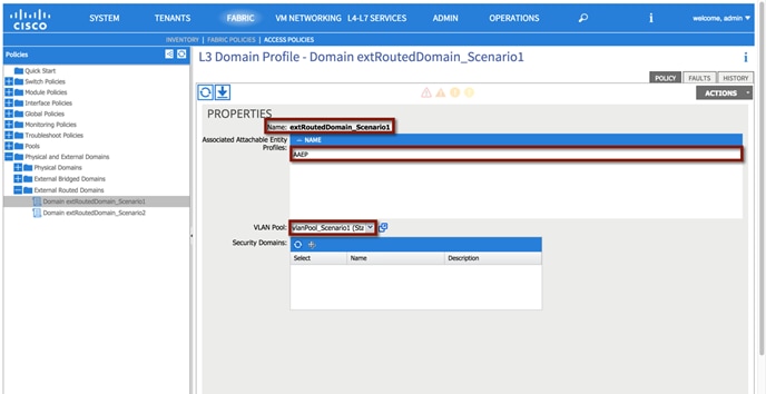
XML 18: Scenario 1 External Routed Domain
<l3extDomP name="extRoutedDomain_Scenario1" >
<!—VLAN Pool Association -->
<infraRsVlanNs tDn="uni/infra/vlanns-[vlanPool_Scenario1]-static"/>
</l3extDomP>
As it was the case for the physical domain, the external routed domain must be associated with an AEP and with a VLAN pool.
Tenant Configuration
Note: The use of the Quick Start guide is not used in order to demonstrate the object relationship for the configuration parameters. Additionally, while Quick Start menus can change from version to version, the method of configuration displayed in this document will not change.
Tenant
A tenant is a logical container for application policies that enable an administrator to exercise domain-based access control. For the sake of the migration study, you will create separate tenants for each scenario. See the following table or the configuration details:
Table 9: Scenario 1 Tenant
| Tenant |
Configuration |
| Name |
Scenario1 |
Note: A tenant represents a unit of isolation from a policy perspective and can represent a customer, an organization or domain in an enterprise setting, or just a convenient grouping of policies.
To configure the tenant, log in to the APIC GUI with administrator privileges and follow the path below:
Tenant à ADD TENANT à [Create Tenant Scenario1]
Figure 60: Scenario 1 Tenant Definition
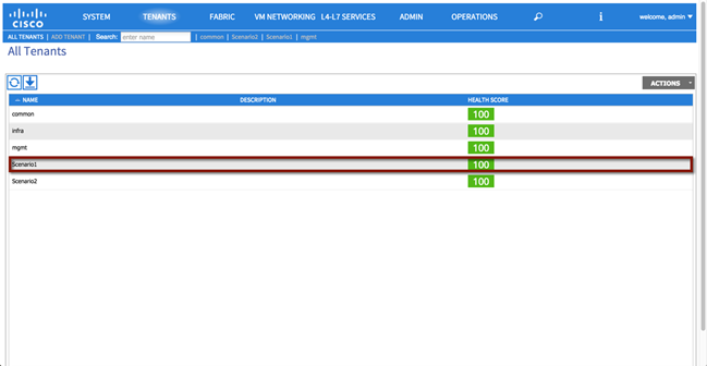
XML 19: Scenario 1 Tenant Definition
<!—Tenant Scenario1 -->
<fvTenant name="Scenario1"/>
Private Network
In this section, you create a private network (VRF100) representing the VRF you are going to associate to the previously created Tenant Scenario1. See the following table or the configuration details:
Table 10: Scenario 1 Private Network
| Private Network |
Configuration |
| Name |
VRF100 |
| Policy Control Enforcement Preference |
Enforced |
For the private network, you will be selecting “enforced” policy control. This ensures that the ACI fabric will use whitelisting model, which means that no Endpoint Group (EPG) will be able to communicate with another endpoint group, unless explicitly permitted with a contract. See the following table or the configuration details:
Note: By enforcing policy control, this means that contracts are required for communication to occur between EPGs.
To configure the private network, log in to the APIC GUI with administrator privileges and follow the path below:
Tenants à [Scenario1] à Networking à Private Networks à [Create VRF100]
Figure 61: Scenario 1 Private Network
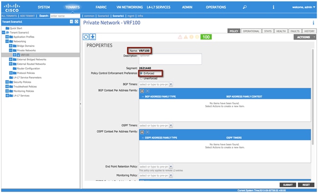
XML 20: Scenario 1 Private Network
<!—Private Network VRF100 -->
<fvCtx descr="" knwMcastAct="permit" name="VRF100" pcEnfPref="enforced">
</fvCtx>
Bridge Domain
In this section, use the following details to create a bridge domain (BD100) representing the Layer 2 broadcast domain that is extended between the FabricPath and the ACI domains. The bridge domain will be associated with the private network VRF100. See the following table for the configuration details:
Table 11: Scenario 1 Bridge Domain
| Bridge Domain |
Configuration |
| Name |
BD100 |
| Private Network |
Scenario1/VRF100 |
| Layer 2 Unknown Unicast |
Flood |
| Layer 2 Unknown Multicast Flooding |
Flood |
| Multi Destination Flooding |
Flood within encapsulation |
| Unicast Routing |
Enabled |
| ARP Flooding |
Enabled |
| Enforce subnet check for IP learning |
Enabled |
This bridge domain will eventually house the pervasive Anycast GW for VLAN 100. All of the EPGs that are defined and used for Scenario 1 will be associated to the same bridge domain BD100.
Table 11 and Figure 62 highlight the specific BD configuration parameters, it is important to point out how the BD must be configured to flood Layer 2 unknown unicast and ARP traffic. This is because you need to ensure that Layer 2 communication can be successfully established between workloads connected to the FP and ACI leaf nodes. The endpoints in the FP domain may not have been discovered yet on the ACI fabric, so flooding will be needed to ensure communication.
To configure the bridge domain, log in to the APIC GUI with administrator privileges and follow the path below:
Tenants à[Scenario1] à Networking à Bridge Domains à [Create BD100]
Figure 62: Scenario 1 Bridge Domain
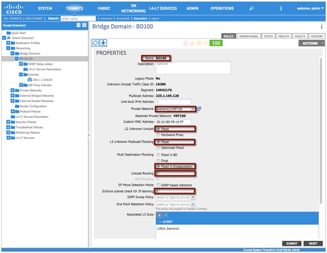
XML 21: Scenario 1 Bridge Domain
<!—Bridge Domain BD100 -->
<fvBD arpFlood="yes" descr="" epMoveDetectMode="" limitIpLearnToSubnets="yes" llAddr="::" mac="00:00:0C:07:AC:64" multiDstPktAct="encap-flood" name="BD100" unicastRoute="yes" unkMacUcastAct="flood" unkMcastAct="flood"/>
Bridge Domain Subnet
One or more IP subnets can be associated to a given bridge domain. In this case, the IP subnet 100.1.1.0/24 is defined for BD100; this is required because one of the steps of the migration procedure consists in moving the default gateway for that IP subnet away from the FP spine devices and into the ACI fabric (the ACI fabric offers a distributed gateway functionality on all the leaf nodes).
As a result of the following configuration, an SVI interface will be created as part of the private network VRF100 to be able to route traffic in and out of IP subnet 100.1.1.0/24.
Note: In order to be able to perform routing functions, the BD must be enabled for unicast routing by setting the corresponding flag shown in the previous screenshot.
Table 12: Scenario 1 Bridge Domain Subnet
| Bridge Domain Subnet |
Configuration |
Description |
| Subnet |
100.1.1.254/24 |
Pervasive Gateway |
| Scope |
Public |
|
This bridge domain will eventually house the pervasive Anycast GW for VLAN 100; a temporary IP address 100.1.1.254 is assigned until then to be able to verify connectivity.
To configure bridge domain subnet, log in to the APIC GUI with administrator privileges and follow the path below:
Tenant à[Scenario1] à Networking à Bridge Domains à [BD100] à Subnets
Figure 63: Scenario 1 Bridge Domain Subnet
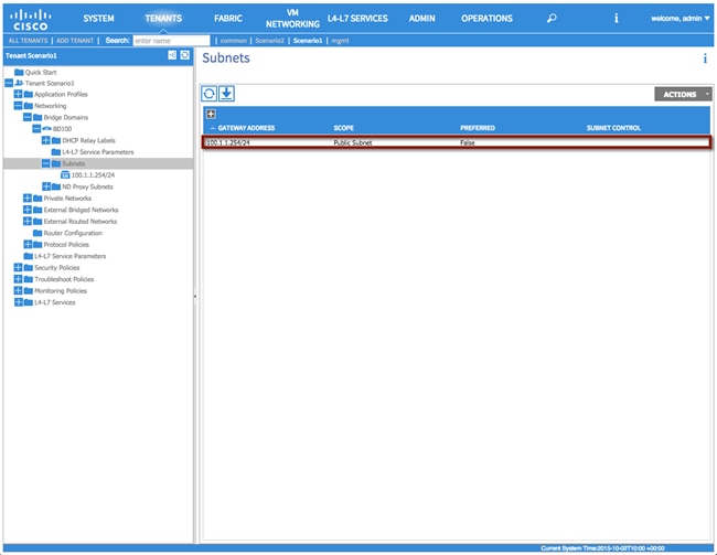
XML 22: Scenario 1 Bridge Domain Subnet
<!—Bridge Domain Subnet -->
<fvSubnet ctrl="" ip="100.1.1.1/24" name="" preferred="no" scope="public"/>
Filter(s)
In this section, use the information in the following table to create a filter. Based on the requirements for Scenario 1, an “any to any” filter is created to allow communication for all devices inside of the ACI fabric with devices outside of the fabric (connected to the FP network). See the following table for the configuration details:
Table 13: Scenario 1 Contract Filter
| Contract Filter |
Configuration |
Description |
| Filter |
any-any |
- |
To configure the contract filter, log in to the APIC GUI with administrator privileges and follow the path below:
Tenants à [Scenario1] à Security Policies à Filters à [Create a filter]
Figure 64: Scenario 1 Contract Filter
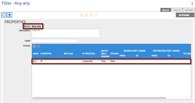
XML 23: Scenario 1 Contract Filter
<!—Contact Filter -->
<vzFilter name="Any-any">
<vzEntry applyToFrag="no" arpOpc="unspecified" dFromPort="unspecified" dToPort="unspecified" descr="" etherT="ip" icmpv4T="unspecified" icmpv6T="unspecified" name="Any" prot="unspecified" sFromPort="unspecified" sToPort="unspecified" stateful="no" tcpRules=""/>
</vzFilter>
Contract(s)
In this section two contracts will be created: “L3Out_Permit_Any” for establishing Layer 3 communications with the routed domain outside of the fabric and “FP_Out_Permit_Any” for allowing Layer 2 communication between endpoints inside of the fabric on VLAN 100, and devices which remain outside of the fabric in the FabricPath environment.
| Contract |
Configuration |
Description |
| Contract1 |
L3Out_Permit_Any |
Layer 3 communication outside of the fabric |
| Contract2 |
FP_OUT_Permit_Any |
Layer 2 communication between endpoints inside of the fabric on VLAN 100, and devices which remain outside of the fabric in the FabricPath environment |
| Filter |
any-any |
|
To configure the contracts, log in to the APIC GUI with administrator privileges and follow the path below:
Tenants à [Scenario1] à Security Policies à Contracts à [L3Out_Permit_Any]
Figure 65: Scenario 1 Contract Definition
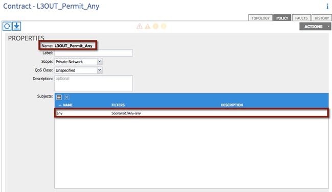
XML 24: Scenario 1 Contract Definition
<!—Contact -->
<vzBrCP name="L3OUT_Permit_Any" prio="unspecified" scope="context">
<vzSubj consMatchT="AtleastOne" descr="" name="any" prio="unspecified" provMatchT="AtleastOne" revFltPorts="yes">
<vzRsSubjFiltAtt tnVzFilterName="Any-any"/>
</vzSubj>
</vzBrCP>
Repeat the process for the remaining Contracts:
Tenants à [Scenario1] à Security Policies à Contracts à [FP_OUT_Permit_Any]
External Routed Network
As previously discussed, static routing is configured between the DC core devices and the ACI border leaf nodes to establish Layer 3 communications in and out of the ACI fabric. HSRP is run between the Cisco Nexus 7000 DC core devices to provide the ACI fabric with a single virtual IP address as next-hop toward the external Layer 3 domain. At the same time, the ACI fabric will define a single floating IP address (used by both border leaf switches) to be used by the DC core devices as next-hop toward the IP subnets defined inside the ACI fabric.
· The ACI fabric defines a 0.0.0.0/0 static routes on each border leaf pointing as next-hop to the HSRP VIP provided by the Cisco Nexus 7000 pair of devices in the DC core on VLAN 49.
· The pair of Cisco Nexus 7000 DC core devices (DCCORE01/02) use a static route to reach the IP subnet associated to the bridge domain BD100 (100.1.1.0/24). The next-hop for the static route is the secondary IP address assigned on both ACI border leaf nodes to the SVI 49. Also, the static route is configured with an admin distance of 254. This will ensure that DCCORE01/02 prefer the OSPF learned route from the FabricPath switches (FP_CORE01/02), until the default gateway for the 100.1.1.0/24 IP subnet is migrated to the ACI fabric (and removed from the FP spines). At that point, the static route to 100.1.1.0/24 will be used to funnel traffic back towards the ACI fabric.
Note: Static routing over the vPC was used for this scenario as there are known issues with dynamic routing over vPCs to other Cisco Nexus platforms (this is not an ACI limitation). You could have also used routed sub-interfaces or routed interfaces to the DCCORE01/02 routers in conjunction with either EIGRP, eBGP, iBGP, or OSPF routing.
In order to complete the configuration of an L3OUT, you will need complete the following tasks:
1. Configure L3Out Properties
2. Configure Logical Node Profiles
3. Configure Logical Interface Profiles
4. Configure L3Out EPG parameters
5. Configure Contracts for the L3Out EPG
Step 1 – L3Out Properties
In this section the External Routed Network, L3Out_Scenario1, will be created. The L3Out will define the network details for reaching Layer 3 networks outside of the ACI fabric domain.
Table 15: Scenario 1 L3Out Properties
| L3OUT |
Configuration |
Description |
| Name |
L3Out_Scenario1 |
- |
| Private Network |
Scenario1/VRF100 |
Associate the L3Out with the proper private network |
| External Routed Domain |
extRoutedDomain_Scenario1 |
Associate the L3Out with the proper external routed domain (this is the previously created domain that contains VLAN 49, which can be used by the L3Out for SVI-based connectivity). |
To configure the external routed network, log in to the APIC GUI with administrator privileges and follow the path below:
Tenants à [Scenario1] à Networking à External Routed Networks à [Create L3OUT_Scenario1]
Figure 66: Scenario 1 L3Out Properties
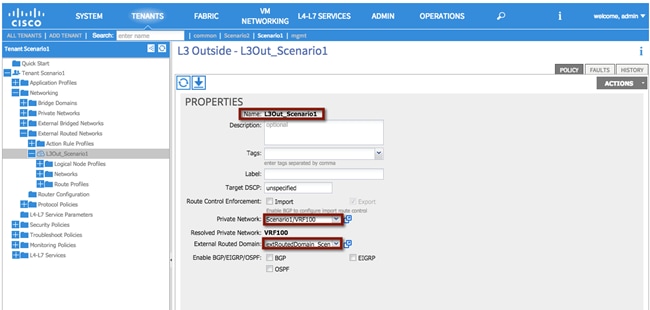
XML 25: Scenario 1 L3Out Properties
<!—External Routed Network – L3OUT -->
<l3extOut enforceRtctrl="export" name="L3Out_Scenario1" targetDscp="unspecified">
<!—Association w/VRF100 -->
<l3extRsEctx tnFvCtxName="VRF100"/>
<!—Association w/External Routed Domain -->
<l3extRsL3DomAtt tDn="uni/l3dom-extRoutedDomain_Scenario1"/>
</l3extOut>
Step 2 – Create Node Profiles
In this section, the external routed network node profile will be created. The node profile defines the fabric nodes that participate in the L3Out connectivity and provides the static route. One logical node profile will be created, specifying the two physical border leaf nodes. A static route is configured on each physical border leaf node pointing to the HSRP VIP address on the DC core devices on VLAN 49.
Table 16: Scenario 1 L3Out Node Profiles
| Node Profile |
Configuration |
Description |
| Name |
Leaf1_2_Node_Profile |
Logical node profile specifying both physical border leaf nodes |
| Node ID |
topology/pod-1/node-101 |
- |
| Router ID |
150.1.1.1 |
(This must be a unique IP address which is NOT in use). The ACI fabric will automatically create a loopback on the associated border leaf with this IP. |
| Static Route |
0.0.0.0/0 |
49.1.1.1 |
| Node ID |
topology/pod-1/node-102 |
- |
| Router ID |
150.1.1.2 |
(This must be a unique IP address which is NOT in use). The ACI Fabric will automatically create a loopback on the associated border leaf with this IP. |
| Static Route |
0.0.0.0/0 |
49.1.1.1 |
To configure the node profile, log in to the APIC GUI with administrator privileges and follow the path below:
Tenants à [Scenario1] à Networking à External Routed Networks à [L3OUT_Scenario1] à Logical Node Profiles à [Create Node_Profile]
Figure 67: Scenario 1 L3Out Node Profiles
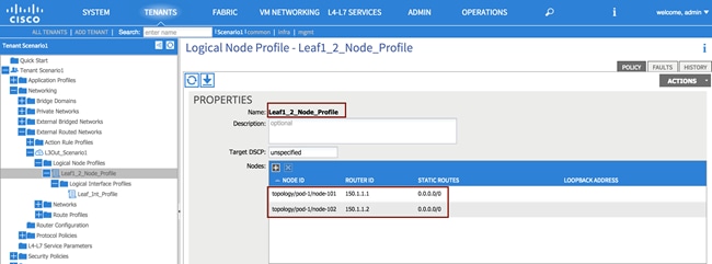
XML 26: Scenario 1 L3Out Node Profile
<l3extOut descr="" enforceRtctrl="export" name="L3Out_Scenario1" targetDscp="unspecified">
<!—Node Profile -->
<l3extLNodeP name="Leaf1_Node_Profile" targetDscp="unspecified">
<!—Node 101 -->
<l3extRsNodeL3OutAtt rtrId="150.1.1.1" rtrIdLoopBack="yes" tDn="topology/pod-1/node-101">
<ipRouteP aggregate="no" ip="0.0.0.0/0" name="" pref="1">
<ipNexthopP descr="" name="" nhAddr="49.1.1.1"/>
</ipRouteP>
</l3extRsNodeL3OutAtt>
<!—Node P102 -->
<l3extRsNodeL3OutAtt rtrId="150.1.1.2" rtrIdLoopBack="yes" tDn="topology/pod-1/node-102">
<ipRouteP aggregate="no" descr="" ip="0.0.0.0/0" name="" pref="1">
<ipNexthopP descr="" name="" nhAddr="49.1.1.1"/>
</ipRouteP>
</l3extRsNodeL3OutAtt>
</l3extOut>
Step 3 – Create Interface Profile
In this section, the interface profile is created to define on both border leaf nodes the SVI interfaces on VLAN 49 to be used for Layer 3 communication with the DC core devices.
Table 17: Scenario 1 L3Out Interface Profile
| Interface Profile |
Description |
|
| Name |
Leaf_Int_Profile |
- |
| Interface Type |
SVI |
- |
| Path Type |
Virtual Port Channel |
- |
| Path |
Node101-102/policyGrpVPC_DCCORE |
Refer to the vPC Interface Policy Group previously created in the “Creation of Virtual Port Channels (vPCs)” section. |
| Encap |
Vlan-49 |
- |
| Site A IP Address |
49.1.1.252/24 |
- |
| Site A Secondary IP Address |
49.1.1.254/24 |
The secondary IP address for Site A MUST match Site B |
| Site B IP Address |
49.1.1.253/24 |
- |
| Site B Secondary IP Address |
49.1.1.252/24 |
The secondary IP address for Site B MUST match Site A |
| MTU |
9000 |
By default the fabric will “inherit” the system MTU, which is 9000. It is considered best practice to manually set the fabric MTU on your interface profile to match the router on the other side. |
To configure the interface profiles, log in to the APIC GUI with administrator privileges and follow the path below:
Tenants à [Scenario1] à Networking à External Routed Networks à [L3OUT_Scenario1] à Logical Node Profiles à [Leaf1_Node_Profiles] à Logical Interface Profiles à [Create Interface_Profiles]
Figure 68: Scenario 1 L3Out Interface Profile
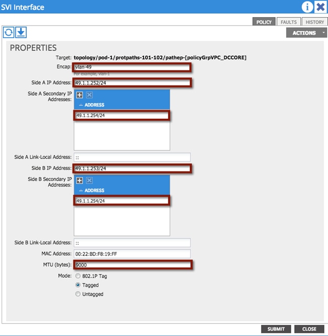
XML 27: Scenario 1 L3Out Interface Profile
<l3extOut descr="" enforceRtctrl="export" name="L3Out_Scenario1" targetDscp="unspecified">
<l3extLNodeP name="Leaf1_Node_Profile" targetDscp="unspecified">
<!—Interface Proile -->
<l3extLIfP descr="" name="Leaf_Int_Profile" tag="yellow-green">
<l3extRsNdIfPol tnNdIfPolName=""/>
<!—SVI -->
<l3extRsPathL3OutAtt addr="0.0.0.0" descr="" encap="vlan-49" ifInstT="ext-svi" llAddr="::" mac="00:22:BD:F8:19:FF" mode="regular" mtu="9000" tDn="topology/pod-1/protpaths-101-102/pathep-[policyGrpVPC_DCCORE]" targetDscp="unspecified">
<!—Interface Proile node 102 -->
<l3extMember addr="49.1.1.253/24" descr="" llAddr="::" name="" side="B">
<l3extIp addr="49.1.1.254/24" descr="" name=""/>
</l3extMember>
<!—Interface Proile node 101 -->
<l3extMember addr="49.1.1.252/24" descr="" llAddr="::" name="" side="A">
<l3extIp addr="49.1.1.254/24" descr="" name=""/>
</l3extMember>
</l3extRsPathL3OutAtt>
</l3extLIfP>
</l3extLNodeP>
</l3extOut>
Step 4 – Create L3Out External Network
The L3Out External Network is defined to represent the external Layer 3 world to the ACI fabric. Multiple external networks can be configured (using IP prefix and mask) to define the external IP prefixes capable of accessing fabric resources within the tenant. A unique external EPG is associated to each defined external network, and this allows you to then apply different security policies (contracts) between each external EPG and EPGs defined internally to the ACI fabric. Without those contracts, all connectivity from outside is blocked and external routes are not learned when using a dynamic routing protocol.
Table 18: Scenario 1 L3Out EPG
| EPG |
Configuration |
Description |
| Name |
L3EPG |
- |
| Subnet |
0.0.0.0/0 |
Defines the external subnets/network, which will be allowed to communicate to the ACI fabric from outside. In this case all the external Layer 3 prefixes can have access to the internal resources (assuming a contract is properly configured). |
| Scope |
Security Import Subnet |
The “Security Import Subnet” flag is set by default and ensures that external traffic matching the configured IP subnet (all the traffic in this example) is properly classified as part of this External EPG (EPG classification on a L3Out is IP subnet based and not VLAN based as on regular Layer 2 interfaces). The field has other functions that are not required to support the use case discussed (used to control route import/export for transit routing scenarios). |
To configure the L3Out external network, log in to the APIC GUI with administrator privileges and follow the path below:
Tenants à [Scenario1] à Networking à External Routed Networks à [L3OUT_Scenario1] à Networks à [L3EPG]
Figure 69: Scenario 1 L3Out External Network
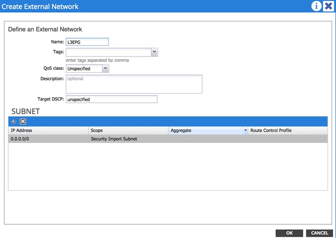
XML 28: Scenario 1 L3Out External Network
<l3extOut descr="" enforceRtctrl="export" name="L3Out_Scenario1" targetDscp="unspecified">
<!—Layer3 EPG -->
<l3extInstP name="L3EPG">
<!—Route Control -->
<l3extSubnet aggregate="" descr="" ip="0.0.0.0/0" scope="import-security"/>
</l3extInstP>
</l3extOut>
Step 5 – Provide a Contract for the L3Out External EPG
In this section, under the Contracts tab for the L3EPG, provide the previously defined L3Out contract (“L3OUT_Permit_Any”). This contract will then be consumed by the internal EPGs to allow successful communication with the external Layer 3 domain.
19: Scenario 1 L3OUT EPG Provider Contract
| Provider Contracts |
Configuration |
Description |
| Name |
L3OUT_Permit_Any |
- |
To configure the provider contract for the external routed network, log in to the APIC GUI with administrator privileges and follow the path below:
Tenants à [Scenario1] à Networking à External Routed Networks à [L3OUT_Scenario1] à Networks à [L3EPG]
Figure 70: Scenario 1 L3Out EPG Provider Contract
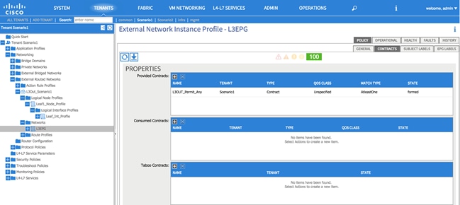
XML 29: Scenario 1 L3Out EPG Provider Contract
<l3extOut descr="" enforceRtctrl="export" name="L3Out_Scenario1" targetDscp="unspecified">
<!—Layer3 EPG -->
<l3extInstP name="L3EPG">
<!—Provider Contract -->
<fvRsProv tnVzBrCPName="L3OUT_Permit_Any"/>
</l3extInstP>
</l3extOut>
Integration Phase – Scenario 1
The next phase is the integration phase. Now that the ACI fabric has been staged, you are going to begin the configuration sections in ACI where you will be establishing connectivity to the FabricPath environment via the vPCs.
Figure 71: Scenario 1 Integration Phase

Application Profiles and EPGs
Application profiles define the policies, services, and relationships between endpoint groups (EPGs). Each application profile contains one or more EPG that can communicate with the other EPGs in the same application profile and with EPGs in other application profiles according to the contract rules.
Create two application profiles: one called AP_IN, which will house the new EPGs and will provide the logical separation between different application endpoints. The second one called AP_OUT, which will house an EPG, mapped to VLAN 100 in the FabricPath domain and that will represent to the ACI Fabric all the endpoints that are still connected to the Brownfield network and the ones that are migrated to the ACI fabric (but not yet relocated to the final Internal EPGs).
Figure 72: Scenario 1 Application Profiles
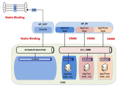
Application Profile AP_IN
In this section, use the information in the following table to create the application profile. Application profiles define the policies, services, and relationships between endpoint groups (EPGs). For Scenario 1 the application profile AP_IN will contain the EPGs for the newly managed application migrated from the FabricPath domain.
Table 20: Scenario 1 Application Profile AP_IN
| Application Profile |
Configuration |
Description |
| Name |
AP_IN |
- |
Note: Each application profile contains one or more EPG that can communicate with the other EPGs in the same application profile and with EPGs in other application profiles according to the contract rules.
To configure the application profile, log in to the APIC GUI with administrator privileges and follow the path below:
Tenants à [Scenario1] à Application Profileà [AP_IN]
Figure 73: Scenario 1 Application Profile AP_IN
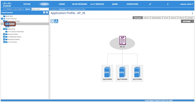
XML 30: Scenario 1 Application Profile AP_IN
<!—Layer3 EPG -->
<fvAp name="AP_IN" />
Internal EPG Definitions
In this section, use the information in the following table to create the internal EPGs (AppOneWeb, AppTwoWeb and AppThreeWeb) part of the previously created application profile.
Table 21: Scenario 1 Internal EPGs
| EPG |
Bridge Domain |
Domain |
| AppOneWeb, AppTwoWeb, AppThreeWeb |
BD100 |
VMware/ACI_VMM |
Note: The EPGs will not consume contracts by configuring this under the EPG. You will consume contracts via a VZANY contract under Tenant à [Scenario1] à Private Network à [VRF100] EPG Collection for Context. This choice allows you to consume the contract for all EPGs associated with that VRF, as opposed to consuming the same contract for each EPG, resulting in a saving of HW resources.
The following screen highlights how to configure AppOneWeb via the APIC GUI. A similar procedure can be followed to configure the other internal EPGs:
Tenants à [Scenario1] à Application Profileà [AP_IN] à Application EPGs à [Create AppOneWeb]
Figure 74: Scenario 1 EPG AppOneWeb
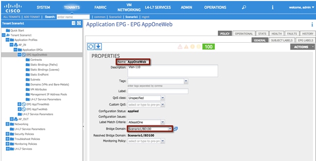
As shown in the previous Figure 73, the internal EPGs part of the AP_IN application profile will only be used to connect virtual machines attached to the ACI-managed DVS (ACI_VMM). As a consequence, the EPGs should only be associated to the corresponding VMM domain, as highlighted in the following screen.
Figure 75: Scenario 1 EPG AppOneWeb Virtual Domain Association
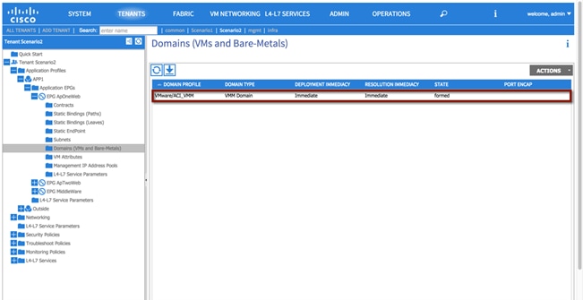
XML 31: Scenario 1 EPG AppOneWeb
<fvAEPg name="AppOneWeb">
<!—EPG Domain association -->
<fvRsDomAtt encap="unknown" instrImedcy="immediate" resImedcy="immediate" tDn="uni/vmmp-VMware/dom-ACI_VMM">
</fvRsDomAtt>
<!—EPG Bridge Domain association -->
<fvRsBd tnFvBDName="BD100"/>
</fvAEPg>
Application Profile AP_OUT
For Scenario 1, the application profile AP_OUT will contain the EPG representing the endpoints still connected to the FP network and the ones already migrated to the ACI fabric domain but not yet connected to the final internal EPG destination.
Table 22: Scenario 1 Application Profile AP_OUT
| Application Profile |
Configuration |
Description |
| Name |
AP_OUT |
- |
To configure the Application Profile AP_OUT, log in to the APIC GUI with administrator privileges and follow the path below:
Tenants à [Scenario1] à Application Profileà [AP_OUT]
EPG Outside
In this section, use the information in the following table to create the endpoint group Outside within the previously created Application Profile AP_OUT. Differently from the internal EPGs previously created, the EPG Outside is associated to the Physical Domain phyDomain_Scenario1 and not to the VMM domain. This is because the EPG will host the VMs that are connected to a vCenter-managed DVS, hence seen as physical servers from the perspective of the ACI fabric.
Table 23: Scenario 1 EPG Outside
| EPG |
Bridge Domain |
Domain |
| Outside |
BD100 |
phyDomain_Scenario1 |
To configure the external routed network EPG, log in to the APIC GUI with administrator privileges and follow the path below:
Tenants à [Scenario1] à Application Profileà [AP_OUT] à Application EPGs à [Outside]
Static Binding
In this section, use the information in the following table to create the static bindings for the EPG Outside. The static bindings will allow you to connect endpoints to the previously created EPG Outside. Those endpoints are VMs still connected to the FP network (and that will communicate with the ACI fabric via the Layer 2 vPC connecting the border leaf nodes to the FP spine devices) and VMs newly migrated to the ACI fabric deployed on the ESXi hosts part of the UCSB-Mini chassis connected to the ACI leaf nodes via FIs.
Table 24: Scenario 1 EPG Outside Static Bindings
| Static Binding |
Configuration |
| Node-101-102/policyGrpVPC_FI_A |
vlan-100 |
| Node-101-102/policyGrpVPC_FI_B |
vlan-100 |
| Node-101-102/policyGrpVPC_FPCORE |
vlan-100 |
To configure static bindings, log in to the APIC GUI with administrator privileges and follow the path below:
Tenants à [Scenario1] à Application Profileà [AP_OUT] à Application EPGs à [Outside] à Static Bindings
Figure 76: Scenario 1 EPG Outside Static Bindings
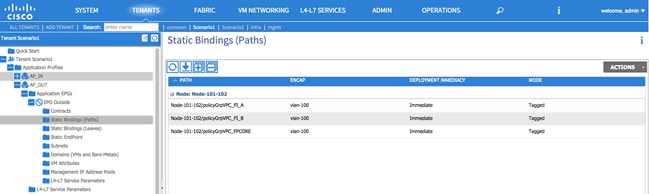
XML 32: Scenario 1 EPG Outside Static Bindings
<fvAEPg name="Outside">
<!—EPG Static Binding FP_CORE-->
<fvRsPathAtt descr="" encap="vlan-100" instrImedcy="immediate" mode="regular" tDn="topology/pod-1/protpaths-101-102/pathep-[policyGrpVPC_FPCORE]"/>
<!—EPG Static Binding FI_A-->
<fvRsPathAtt descr="" encap="vlan-100" instrImedcy="immediate" mode="regular" tDn="topology/pod-1/protpaths-101-102/pathep-[policyGrpVPC_FI_A]"/>
<!—EPG Static Binding FI_B-->
<fvRsPathAtt descr="" encap="vlan-100" instrImedcy="immediate" mode="regular" tDn="topology/pod-1/protpaths-101-102/pathep-[policyGrpVPC_FI_B]"/>
<fvRsDomAtt encap="unknown" instrImedcy="immediate" resImedcy="immediate" tDn="uni/phys-phyDomain_Scenario1"/>
<fvRsBd tnFvBDName="BD100"/>
<fvRsProv tnVzBrCPName="FP_Out_Permit_Any"/>
</fvAEPg>
EPG Outside Provider Contract
In this section, you will define the contract provided by the Outside EPG (FP_Out_Permit_Any) to allow communications with workloads connected to the internal EPGs.
Table 25: Scenario 1 EPG Outside Provider Contract
| Provider Contract |
Configuration |
Description |
| Name |
FP_Out_Permit_Any |
Contract to allow connectivity outside of the fabric |
To configure a contract association, log in to the APIC GUI with administrator privileges and follow the path below:
Tenants à [Scenario1] à Application Profileà [AP_OUT] à Application EPGs à [Outside] à Contracts à [Create Add Provided Contract]
Figure 77: Scenario 1 EPG Outside Provider Contract
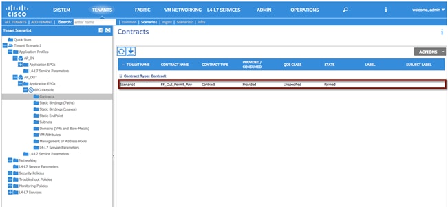
XML 33: Scenario 1 EPG Outside Provider Contract
<fvAEPg name="Outside">
<!—EPG Provider Contract association-->
<fvRsProv tnVzBrCPName="FP_Out_Permit_Any"/>
</fvAEPg>
Consuming a vzANY contract
The final step needed in order to allow traffic to flow between the Outside EPG and the previously defined internal EPGs (WebAppOne, WebAppTwo and WebAppThree) in and out of the EPGs is to consume a VZANY contract.
Consuming the contract under the private network [VRF100] allows the configuration to consume the contract on behalf of all EPGs associated with that VRF, as opposed to consuming the same contract for each EPG.
Figure 78: Scenario 1 Consuming vzANY
|
|
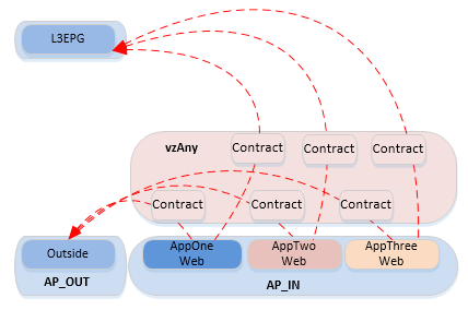
To configure a vzANY contract association, log in to the APIC GUI with administrator privileges and follow the path below:
Tenant à [Scenario1] à Private Network à [VRF100] EPG Collection for Context.
Figure 79: Scenario 1 vzANY
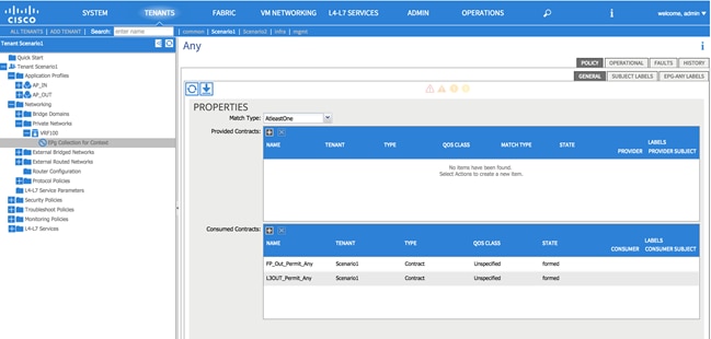
XML 34: Scenario 1 vzANY
<fvCtx name="VRF100">
<!—vzANY Contract-->
<vzAny descr="" matchT="AtleastOne" name="">
<!—vzANY Provide-->
<vzRsAnyToCons prio="unspecified" tnVzBrCPName="FP_Out_Permit_Any"/>
<!—vzANY Consume-->
<vzRsAnyToCons prio="unspecified" tnVzBrCPName="L3OUT_Permit_Any"/>
</vzAny>
</fvCtx>
Migration Phase – Scenario 1
Now that Layer 2 connectivity is established between the ACI fabric and the FabricPath environment for VLAN 100, as well as Layer 3 connectivity from ACI to the DC core routers (DCCORE01/02), VM integration to vCenter is complete, and the contracts are in place. It is time to start migrating application VMs from the FabricPath environment into the ACI fabric.
Figure 80: Scenario 1 Migration Phase
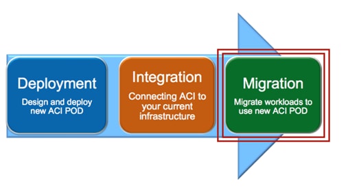
Applications within this scenario are currently deployed in a single FabricPath VLAN (VLAN 100), that is, the Web Server (1), Web Server (2), Web Server (3), and so on, currently reside in the same address space within the single VLAN. The intent of the migration is to provide separation of services, that is, provide logical separation of applications, between each of the web server environments.
Note: Although the FabricPath topology is used as part of the migration efforts described herein, STP, vPC, or other topologies could leverage the overall strategy and process.
The migration plan includes the following steps that are detailed in the upcoming sections:
1. Premigration Validation: the intent of this step is to ensure that the current environment including applications is behaving as intended and will include confirmation of various connectivity checks.
2. Application Migration: this step will be accomplished by migrating the application within vCenter from the ESXi host connected to the FabricPath network to the ESXi host connected to the ACI fabric using vMotion.
3. Port Group Migration: this step involves migrating the host VM VMNIC from the standard DVS port group to the ACI-managed DVS port group.
4. Gateway Migration: this step includes migrating the gateway and Layer 3 functionalities from the FabricPath domain to the ACI fabric.
5. Continue Server Migration: within this step of the migration, additional server migration efforts continue until the point where all applications/servers have been migrated from the FabricPath domain to the ACI fabric.
Premigration Validation
The following are some important premigration assumptions:
· All virtual hosts attached to the vCenter-managed DVS are using the FabricPath spines as their Layer 3 gateway. Layer 2 communication between the VMs and the default gateway is achieved by stretching the Layer 2 broadcast domain across the FP network and by trunking VLAN 100 from the FP leaf devices down to the UCS chassis where the ESXi host resides.
· All virtual hosts attached to the vCenter-managed DVS exit the data center via Layer 3 connectivity through the DCCORE switches by learning external IP prefixes via OSPF control plane.
· The ESXi host connected to the FabricPath domain has uplinks connected to the vCenter-managed DVS (dvSwitchFabricPath).
· The ESXi host connected to the ACI fabric has uplinks connected to the vCenter-managed DVS (dvSwitchFabricPath) and to the ACI-managed DVS (ACI_VMM).
· All VMs are using shared storage (iSCSI), which is available for both the ESXi hosts in the FabricPath and ACI environments. This is what allows live vMotions to occur.
· Layer 2 connectivity from the FabricPath domain to the ACI fabric is successfully established via the Layer 2 vPC logical connection.
· The same Layer 2 broadcast domain is extended from the FabricPath network to the ACI fabric and allows Layer 2 connectivity between VMs deployed on the ESXi hosts connected to the FabricPath and ACI domains.
The following diagram shows the application host VM, AppOneWeb, which will be the initial host VM migrated from the FabricPath domain to the ACI fabric.
Figure 81: Scenario 1 AppOneWeb VM
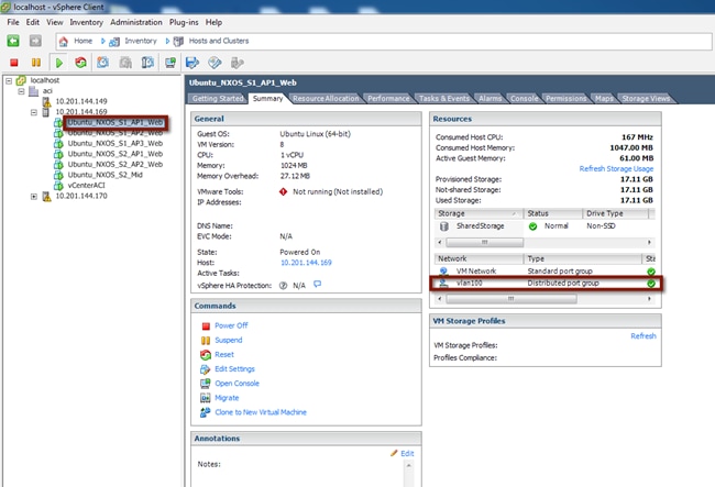
The following diagram depicts the entire topology including the Layer 2 connectivity. AppOneWeb is currently located on the ESXi host in the FabricPath environment and connected to the VLAN100 port group on the vCenter-managed DVS.
Figure 82: Scenario 1 Premigration Topology
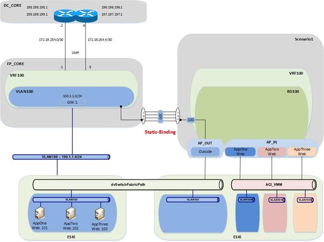
Validation
The initial validation step includes the following connectivity test from the host VM, AppOneWeb. The first validation test ensures that the correct interface on the VM has the required IP address and ARP entries. Connectivity confirmation via ping and traceroute allow for gateway and core reachability path and response test.
Figure 83: Scenario 1 Premigration Validation – AppOneWeb IP Address
IFCONFIG::
cisco@AppOneWeb:~$ ifconfig eth0
eth0 Link encap:Ethernet HWaddr 00:50:56:82:bd:bf
inet addr:100.1.1.101 Bcast:100.1.1.255 Mask:255.255.255.0
inet6 addr: fe80::250:56ff:fe82:bdbf/64 Scope:Link
UP BROADCAST RUNNING MULTICAST MTU:1500 Metric:1
RX packets:25 errors:0 dropped:3 overruns:0 frame:0
TX packets:75 errors:0 dropped:0 overruns:0 carrier:0
collisions:0 txqueuelen:1000
RX bytes:2204 (2.2 KB) TX bytes:10778 (10.7 KB)
cisco@AppOneWeb:~$
Figure 84: Scenario 1 Premigration Validation – AppOneWeb ARP Cache
ARP –A:
cisco@AppOneWeb:~$ arp -a
? (100.1.1.1) at 00:00:0c:07:ac:64 [ether] on eth0
? (100.1.1.102) at 00:50:56:82:d4:69 [ether] on eth0
? (100.1.1.103) at 00:50:56:82:d5:05 [ether] on eth0
cisco@AppOneWeb:~$
cisco@AppOneWeb:~$
In the following example, note that AppOneWeb can ping its GW (100.1.1.1) and the two other AppServers in VLAN 100 (100.1.1.102 and 100.1.1.103, respectively).
Figure 85: Scenario 1 Premigration Validation – Ping tests
PING::
cisco@AppOneWeb:~$ ping 100.1.1.1 -c 1
PING 100.1.1.1 (100.1.1.1) 56(84) bytes of data.
64 bytes from 100.1.1.1: icmp_seq=1 ttl=63 time=0.218 ms
--- 100.1.1.1 ping statistics ---
1 packets transmitted, 1 received, 0% packet loss, time 0ms
rtt min/avg/max/mdev = 0.218/0.218/0.218/0.000 ms
cisco@AppOneWeb:~$
cisco@AppOneWeb:~$ ping 100.1.1.102 -c 1
PING 100.1.1.102 (100.1.1.102) 56(84) bytes of data.
64 bytes from 100.1.1.102: icmp_seq=1 ttl=64 time=0.285 ms
--- 100.1.1.102 ping statistics ---
1 packets transmitted, 1 received, 0% packet loss, time 0ms
rtt min/avg/max/mdev = 0.285/0.285/0.285/0.000 ms
cisco@AppOneWeb:~$
cisco@AppOneWeb:~$ ping 100.1.1.103 -c 1
PING 100.1.1.103 (100.1.1.103) 56(84) bytes of data.
64 bytes from 100.1.1.103: icmp_seq=1 ttl=64 time=0.163 ms
--- 100.1.1.103 ping statistics ---
1 packets transmitted, 1 received, 0% packet loss, time 0ms
rtt min/avg/max/mdev = 0.163/0.163/0.163/0.000 ms
cisco@AppOneWeb:~$
cisco@AppOneWeb:~$ ping 199.199.199.1 -c 1
PING 199.199.199.1 (199.199.199.1) 56(84) bytes of data.
64 bytes from 199.199.199.1: icmp_seq=1 ttl=253 time=0.577 ms
--- 199.199.199.1 ping statistics ---
1 packets transmitted, 1 received, 0% packet loss, time 0ms
rtt min/avg/max/mdev = 0.577/0.577/0.577/0.000 ms
cisco@AppOneWeb:~$
Note as follows that the traceroute to 199.199.199.1 (a loopback on DCCORE01) shows that the path goes through the FabricPath environment.
Figure 86: Scenario 1 Premigration Validation – Traceroute tests
TRACEROUTE::
cisco@AppOneWeb:~$ traceroute 100.1.1.1
traceroute to 100.1.1.1 (100.1.1.1), 30 hops max, 60 byte packets
1 100.1.1.1 (100.1.1.1) 0.774 ms 0.845 ms 0.955 ms
cisco@AppOneWeb:~$
cisco@AppOneWeb:~$ traceroute 199.199.199.1
traceroute to 199.199.199.1 (199.199.199.1), 30 hops max, 60 byte packets
1 100.1.1.1 (100.1.1.1) 0.381 ms 0.528 ms 0.683 ms
2 100.1.1.1 (100.1.1.1) 0.839 ms 1.038 ms 1.145 ms
3 199.199.199.1 (199.199.199.1) 1.183 ms 1.257 ms 1.357 ms
cisco@AppOneWeb:~$
The second validation step includes the following connectivity test from the FabricPath Cisco Nexus 7000 Switches. The MAC address and ARP entries are queried to ensure that the Cisco Nexus 7000 switches can see the AppOneWeb VM.
In the following example, note that the MAC address of AppOneWeb is 0050.5682.bdbf and 1122 is the FabricPath SwitchID of the access-layer Cisco Nexus 5600 where the ESXi hosts is connected.
Figure 87: Scenario 1 Validation – FabricPath domain
SHOW MAC ADDRESS-TABLE::
FP_Core01# show mac address-table address 0050.5682.bdbf
Note: MAC table entries displayed are getting read from software.
Use the 'hardware-age' keyword to get information related to 'Age'
Legend:
* - primary entry, G - Gateway MAC, (R) - Routed MAC, O - Overlay MAC
age - seconds since last seen,+ - primary entry using vPC Peer-Link,
(T) - True, (F) - False , ~~~ - use 'hardware-age' keyword to retrieve age info
VLAN MAC Address Type age Secure NTFY Ports/SWID.SSID.LID
---------+-----------------+--------+---------+------+----+------------------
100 0050.5682.bdbf dynamic ~~~ F F 1122.0.0
FP_Core01#
Figure 87: Scenario 1 Validation – ARP validation
SHOW IP ARP::
FP_Core01# show ip arp 100.1.1.101
Flags: * - Adjacencies learnt on non-active FHRP router
+ - Adjacencies synced via CFSoE
# - Adjacencies Throttled for Glean
D - Static Adjacencies attached to down interface
IP ARP Table
Total number of entries: 1
Address Age MAC Address Interface
100.1.1.101 00:00:04 0050.5682.bdbf Vlan100
FP_Core01#
Figure 88: Scenario 1 Validation – Routing Table validation
SHOW IP ROUTE::
FP_Core01# show ip route 100.1.1.0/24
IP Route Table for VRF "default"
'*' denotes best ucast next-hop
'**' denotes best mcast next-hop
'[x/y]' denotes [preference/metric]
'%<string>' in via output denotes VRF <string>
100.1.1.0/24, ubest/mbest: 1/0, attached
*via 100.1.1.2, Vlan100, [0/0], 00:01:16, direct
FP_Core01#
The third validation step includes the following connectivity test from the ACI fabric. The endpoint connectivity and the route validation are used to confirm the endpoint discovery process and correct routing entry. Note that you can expect to see nothing from the ACI perspective during this test. The VM is on the FabricPath-attached ESXi host, and the gateway for VLAN 100 still resides in the FabricPath environment.
Figure 89: Scenario 1 Validation – ACI Fabric
SHOW ENDPOINT::
Leaf1# show endpoint ip 100.1.1.101
Legend:
O - peer-attached H - vtep a - locally-aged S - static
V - vpc-attached p - peer-aged L - local M - span
s - static-arp B - bounce
+-------------------+---------------+-----------------+--------------+-------------+
VLAN/ Encap MAC Address MAC Info/ Interface
Domain VLAN IP Address IP Info
+-------------------+---------------+-----------------+--------------+-------------+
Leaf1#
Figure 90: Scenario 1 Validation – Routing table Validation
SHOW IP ROUTE::
Leaf1# show ip route vrf Scenario1:VRF100 100.1.1.0/24
IP Route Table for VRF "Scenario1:VRF100"
'*' denotes best ucast next-hop
'**' denotes best mcast next-hop
'[x/y]' denotes [preference/metric]
'%<string>' in via output denotes VRF <string>
100.1.1.0/24, ubest/mbest: 1/0, attached, direct, pervasive
*via 10.0.40.65%overlay-1, [1/0], 6d04h, static
recursive next hop: 10.0.40.65/32%overlay-1
Leaf1#
Application Migration
Following the premigration steps, the next step consists of performing a live migration (vMotion) of the AppOneWeb VM from the ESXi server in the FabricPath environment to the ESXi server in the ACI environment. This step requires a vCenter administrator to initiate a ‘migrate’ virtual machine event.
Figure 91: Scenario 1 Host Migration
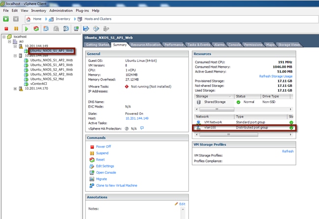
Following the live migration event, the virtual machine will leverage the Layer 2 connectivity established via the Layer 2 vPC logical connection to communicate to the other VMs still connected to the FP network and to its default gateway still deployed to the FP spine devices.
To validate the vMotion of the virtual machine and the continue communication with the infrastructure, start a continuous ping from AppOneWeb to the gateway. During the host migration, document any pack lost or abnormality. As shown below, only two ICMP packets have been lost during the live migration process.
Figure 92: Scenario 1 Host Migration Ping
cisco@AppOneWeb:~$ ping 100.1.1.1
PING 100.1.1.1 (100.1.1.1) 56(84) bytes of data.
64 bytes from 100.1.1.1: icmp_seq=1 ttl=255 time=0.480 ms
64 bytes from 100.1.1.1: icmp_seq=2 ttl=255 time=0.494 ms
64 bytes from 100.1.1.1: icmp_seq=3 ttl=255 time=0.507 ms
64 bytes from 100.1.1.1: icmp_seq=4 ttl=255 time=0.500 ms
64 bytes from 100.1.1.1: icmp_seq=5 ttl=255 time=0.505 ms
64 bytes from 100.1.1.1: icmp_seq=6 ttl=255 time=0.571 ms
64 bytes from 100.1.1.1: icmp_seq=7 ttl=255 time=0.495 ms
64 bytes from 100.1.1.1: icmp_seq=8 ttl=255 time=0.557 ms
64 bytes from 100.1.1.1: icmp_seq=11 ttl=255 time=1.16 ms
64 bytes from 100.1.1.1: icmp_seq=12 ttl=255 time=1.08 ms
64 bytes from 100.1.1.1: icmp_seq=13 ttl=255 time=1.10 ms
^C
--- 100.1.1.1 ping statistics ---
17 packets transmitted, 15 received, 11% packet loss, time 16023ms
rtt min/avg/max/mdev = 0.480/0.800/1.261/0.310 ms
cisco@AppOneWeb:~$
AppOneWeb VM is now on the standard DVS on the ESXi host in the ACI fabric environment with gateway reachability remaining on the FabricPath Spine.
Figure 93: Scenario 1 Migrate Host from FabricPath Domain to ACI Fabric
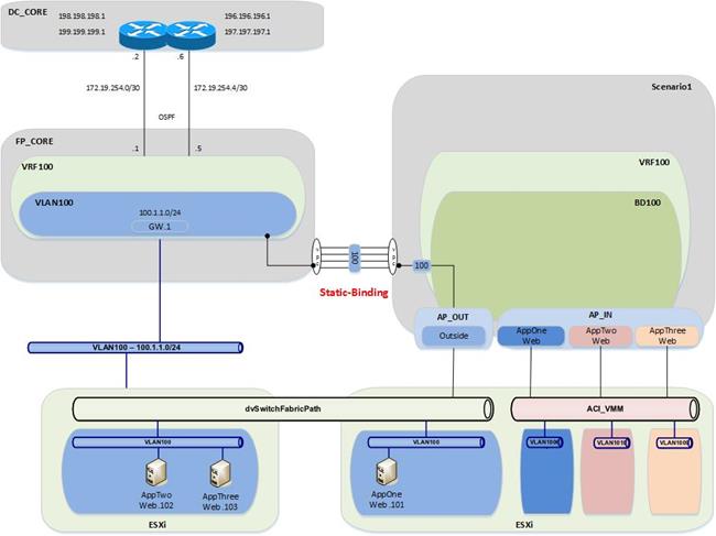
Validation
The first validation step includes the following connectivity test from the virtual host, AppOneWeb, to ensure network access.
In the following figure, note that the interface on the VM has the required IP address and ARP entries. Connectivity confirmation via ping and traceroute allows for gateway and core reachability path and response test.
Figure 94: Scenario 1 Migrate Host to ACI – AppOneWeb
IFCONFIG::
cisco@AppOneWeb:~$ ifconfig eth0
eth0 Link encap:Ethernet HWaddr 00:50:56:82:bd:bf
inet addr:100.1.1.101 Bcast:100.1.1.255 Mask:255.255.255.0
inet6 addr: fe80::250:56ff:fe82:bdbf/64 Scope:Link
UP BROADCAST RUNNING MULTICAST MTU:1500 Metric:1
RX packets:25 errors:0 dropped:3 overruns:0 frame:0
TX packets:75 errors:0 dropped:0 overruns:0 carrier:0
collisions:0 txqueuelen:1000
RX bytes:2204 (2.2 KB) TX bytes:10778 (10.7 KB)
cisco@AppOneWeb:~$
Figure 95: Scenario 1 Migrate Host to ACI – AppOneWeb ARP Validation
ARP –A:
cisco@AppOneWeb:~$ arp –a
? (100.1.1.102) at 00:50:56:82:d4:69 [ether] on eth0
? (100.1.1.1) at 00:00:0c:07:ac:64 [ether] on eth0
? (100.1.1.103) at 00:50:56:82:d5:05 [ether] on eth0
cisco@AppOneWeb:~$
In the following example, note that you still have ICMP reachability to the gateway and all other application VMs in VLAN 100.
Figure 96: Scenario 1 Migrate Host to ACI – AppOneWeb Ping Validation
PING::
cisco@AppOneWeb:~$ ping 100.1.1.1 -c 1
PING 100.1.1.1 (100.1.1.1) 56(84) bytes of data.
64 bytes from 100.1.1.1: icmp_seq=1 ttl=255 time=1.31 ms
--- 100.1.1.1 ping statistics ---
1 packets transmitted, 1 received, 0% packet loss, time 0ms
rtt min/avg/max/mdev = 1.318/1.318/1.318/0.000 ms
cisco@AppOneWeb:~$
cisco@AppOneWeb:~$ ping 100.1.1.102 -c 1
PING 100.1.1.102 (100.1.1.102) 56(84) bytes of data.
64 bytes from 100.1.1.102: icmp_seq=1 ttl=64 time=0.346 ms
--- 100.1.1.102 ping statistics ---
1 packets transmitted, 1 received, 0% packet loss, time 0ms
rtt min/avg/max/mdev = 0.346/0.346/0.346/0.000 ms
cisco@AppOneWeb:~$
cisco@AppOneWeb:~$ ping 100.1.1.103 -c 1
PING 100.1.1.103 (100.1.1.103) 56(84) bytes of data.
64 bytes from 100.1.1.103: icmp_seq=1 ttl=64 time=0.379 ms
--- 100.1.1.103 ping statistics ---
1 packets transmitted, 1 received, 0% packet loss, time 0ms
rtt min/avg/max/mdev = 0.379/0.379/0.379/0.000 ms
cisco@AppOneWeb:~$
cisco@AppOneWeb:~$ ping 199.199.199.1 -c 1
PING 199.199.199.1 (199.199.199.1) 56(84) bytes of data.
64 bytes from 199.199.199.1: icmp_seq=1 ttl=254 time=0.467 ms
--- 199.199.199.1 ping statistics ---
1 packets transmitted, 1 received, 0% packet loss, time 0ms
rtt min/avg/max/mdev = 0.467/0.467/0.467/0.000 ms
cisco@AppOneWeb:~$
In the following example, note that the traceroute still shows that you are going through the FabricPath environment to reach the loopback (199.199.199.1) on DCCORE01.
Figure 97: Scenario 1 Migrate Host to ACI – AppOneWeb Traceroute Validation
TRACEROUTE::
cisco@AppOneWeb:~$ traceroute 100.1.1.1
traceroute to 100.1.1.1 (100.1.1.1), 30 hops max, 60 byte packets
1 100.1.1.1 (100.1.1.1) 2.315 ms 0.906 ms 3.375 ms
cisco@AppOneWeb:~$
cisco@AppOneWeb:~$ traceroute 199.199.199.1
traceroute to 199.199.199.1 (199.199.199.1), 30 hops max, 60 byte packets
1 * * 100.1.1.2 (100.1.1.2) 1.216 ms
2 * * 199.199.199.1 (199.199.199.1) 1.354 ms
cisco@AppOneWeb:~$
The second validation step includes verifying the MAC address and ARP entries to ensure the virtual server connectivity is as intended.
In the following example, note that the MAC address for AppOneWeb has moved to the Port-channel 11 that connects to the ACI environment.
Figure 98: Scenario 1 Validation – FP Fabric
SHOW MAC ADDRESS-TABLE::
FP_Core01# show mac address-table address 0050.5682.bdbf
Note: MAC table entries displayed are getting read from software.
Use the 'hardware-age' keyword to get information related to 'Age'
Legend:
* - primary entry, G - Gateway MAC, (R) - Routed MAC, O - Overlay MAC
age - seconds since last seen,+ - primary entry using vPC Peer-Link,
(T) - True, (F) - False , ~~~ - use 'hardware-age' keyword to retrieve age info
VLAN MAC Address Type age Secure NTFY Ports/SWID.SSID.LID
---------+-----------------+--------+---------+------+----+------------------
* 100 0050.5682.bdbf dynamic ~~~ F F Po11
SHOW IP ARP::
FP_Core01# show ip arp 100.1.1.101
Flags: * - Adjacencies learnt on non-active FHRP router
+ - Adjacencies synced via CFSoE
# - Adjacencies Throttled for Glean
D - Static Adjacencies attached to down interface
IP ARP Table
Total number of entries: 1
Address Age MAC Address Interface
100.1.1.101 00:00:25 0050.5682.bdbf Vlan100
FP_Core01#
Figure 99: Scenario 1 Validation – FP Fabric Routing Table
SHOW IP ROUTE::
FP_Core01# show ip route 100.1.1.0/24
IP Route Table for VRF "default"
'*' denotes best ucast next-hop
'**' denotes best mcast next-hop
'[x/y]' denotes [preference/metric]
'%<string>' in via output denotes VRF <string>
100.1.1.0/24, ubest/mbest: 1/0, attached
*via 100.1.1.2, Vlan100, [0/0], 00:03:51, direct
FP_Core01#
The third validation step includes the following connectivity test from the ACI fabric. The endpoint connectivity and the route validation are used to confirm the endpoint discovery process and correct routing entry.
In the following example, note that the ACI fabric now sees the AppOneWeb VM as an endpoint. With the show endpoint command, you can see both the IP and MAC address for the VM.
Figure 100: Scenario 1 Validation – ACI Fabric
SHOW ENDPOINT::
Leaf1# show endpoint ip 100.1.1.101
Legend:
O - peer-attached H - vtep a - locally-aged S - static
V - vpc-attached p - peer-aged L - local M - span
s - static-arp B - bounce
+-------------------+---------------+-----------------+--------------+-------------+
VLAN/ Encap MAC Address MAC Info/ Interface
Domain VLAN IP Address IP Info
+-------------------+---------------+-----------------+--------------+-------------+
22 vlan-100 0050.5682.bdbf LV po13
Scenario1:VRF100 vlan-100 100.1.1.101 LV
Leaf1#
Figure 101: Scenario 1 Validation – ACI Fabric Routing Table
SHOW IP ROUTE::
Leaf1# show ip route vrf Scenario1:VRF100 100.1.1.0/24
IP Route Table for VRF "Scenario1:VRF100"
'*' denotes best ucast next-hop
'**' denotes best mcast next-hop
'[x/y]' denotes [preference/metric]
'%<string>' in via output denotes VRF <string>
100.1.1.0/24, ubest/mbest: 1/0, attached, direct, pervasive
*via 10.0.40.65%overlay-1, [1/0], 01w07d, static
recursive next hop: 10.0.40.65/32%overlay-1
Leaf1#
Port Group Migration
Now that you have the AppOneWeb VM on the ESXi host in the ACI fabric, the next step in the migration involves migrating the application AppOneWeb from the standard DVS to the ACI-managed DVS. This step requires a vCenter administrator to edit the settings of the virtual machine to modify the VMNIC association.
Following the port group migration, the gateway remains within the FabricPath domain.
Port Group Move
Move the VMNIC from the standard DVS to the ACI-managed DVS.
Figure 102: Scenario 1 vCenter Port Group Migration
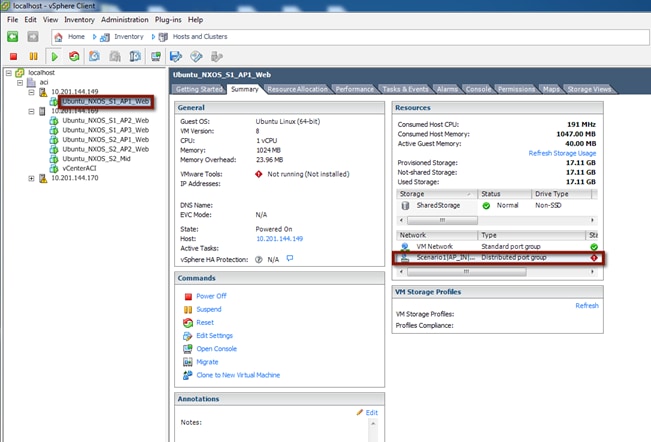
To validate the port group change of the virtual machine and the continued communication with the infrastructure, start a continuous ping from AppOneWeb to the gateway. During the host port group association change, document any packet loss or abnormality.
In the following example, note that you can still ping the default gateway (still the FabricPath Spine) and no connectivity is lost while migrating the VMNIC between port groups.
Figure 103: Scenario 1 Port Group Migration Validations
cisco@AppOneWeb:~$ ping 100.1.1.1
PING 100.1.1.1 (100.1.1.1) 56(84) bytes of data.
64 bytes from 100.1.1.1: icmp_seq=1 ttl=255 time=1.11 ms
64 bytes from 100.1.1.1: icmp_seq=2 ttl=255 time=1.54 ms
64 bytes from 100.1.1.1: icmp_seq=3 ttl=255 time=1.01 ms
64 bytes from 100.1.1.1: icmp_seq=4 ttl=255 time=1.06 ms
64 bytes from 100.1.1.1: icmp_seq=5 ttl=255 time=0.978 ms
^C
--- 100.1.1.1 ping statistics ---
24 packets transmitted, 24 received, 0% packet loss, time 23029ms
rtt min/avg/max/mdev = 0.978/1.102/1.540/0.111 ms
cisco@AppOneWeb:~$
Following the port group association update, you can now see that the host appears within the topology connected to the second ESXi host on the ACI-managed DVS and port group.
Figure 104: Scenario 1 Migrate Port Group Migration
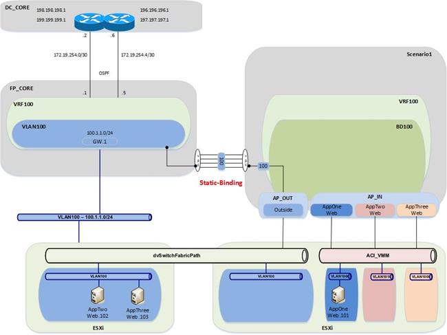
Validation
Now that you have changed the port group for the AppOneWeb VM, you will repeat all of the verification steps.
Figure 105: Scenario 1 Migrate Host to ACI – AppOneWeb
IFCONFIG::
cisco@AppOneWeb:~$ ifconfig eth0
eth0 Link encap:Ethernet HWaddr 00:50:56:82:bd:bf
inet addr:100.1.1.101 Bcast:100.1.1.255 Mask:255.255.255.0
inet6 addr: fe80::250:56ff:fe82:bdbf/64 Scope:Link
UP BROADCAST RUNNING MULTICAST MTU:1500 Metric:1
RX packets:1335 errors:0 dropped:33 overruns:0 frame:0
TX packets:925 errors:0 dropped:0 overruns:0 carrier:0
collisions:0 txqueuelen:1000
RX bytes:94188 (94.1 KB) TX bytes:59038 (59.0 KB)
cisco@AppOneWeb:~$
Figure 106: Scenario 1 Migrate Host to ACI – AppOneWeb ARP Validation
ARP –A:
cisco@AppOneWeb:~$ arp –a
? (100.1.1.102) at 00:50:56:82:d4:69 [ether] on eth0
? (100.1.1.1) at 00:00:0c:07:ac:64 [ether] on eth0
? (100.1.1.103) at 00:50:56:82:d5:05 [ether] on eth0
cisco@AppOneWeb:~$
In the following example, note that there is still ICMP reachability to all other Application VMs in VLAN 100.
Figure 107: Scenario 1 Migrate Host to ACI – AppOneWeb Ping Validation
PING::
cisco@AppOneWeb:~$ ping 100.1.1.1 -c 1
PING 100.1.1.1 (100.1.1.1) 56(84) bytes of data.
64 bytes from 100.1.1.1: icmp_seq=1 ttl=255 time=1.20 ms
--- 100.1.1.1 ping statistics ---
1 packets transmitted, 1 received, 0% packet loss, time 0ms
rtt min/avg/max/mdev = 1.206/1.206/1.206/0.000 ms
cisco@AppOneWeb:~$
cisco@AppOneWeb:~$ ping 100.1.1.102 -c 1
PING 100.1.1.102 (100.1.1.102) 56(84) bytes of data.
64 bytes from 100.1.1.102: icmp_seq=1 ttl=64 time=0.431 ms
--- 100.1.1.102 ping statistics ---
1 packets transmitted, 1 received, 0% packet loss, time 0ms
rtt min/avg/max/mdev = 0.431/0.431/0.431/0.000 ms
cisco@AppOneWeb:~$
cisco@AppOneWeb:~$ ping 100.1.1.103 -c 1
PING 100.1.1.103 (100.1.1.103) 56(84) bytes of data.
64 bytes from 100.1.1.103: icmp_seq=1 ttl=64 time=0.325 ms
--- 100.1.1.103 ping statistics ---
1 packets transmitted, 1 received, 0% packet loss, time 0ms
rtt min/avg/max/mdev = 0.325/0.325/0.325/0.000 ms
cisco@AppOneWeb:~$
cisco@AppOneWeb:~$ ping 199.199.199.1 -c 1
ING 199.199.199.1 (199.199.199.1) 56(84) bytes of data.
64 bytes from 199.199.199.1: icmp_seq=1 ttl=254 time=0.516 ms
--- 199.199.199.1 ping statistics ---
1 packets transmitted, 1 received, 0% packet loss, time 0ms
rtt min/avg/max/mdev = 0.516/0.516/0.516/0.000 ms
cisco@AppOneWeb:~$
In the following example, note that the traceroute still shows that you are going through the FabricPath environment to reach the loopback (199.199.199.1) on DCCORE01.
Figure 108: Scenario 1 Migrate Host to ACI – AppOneWeb Traceroute Validation
TRACEROUTE::
cisco@AppOneWeb:~$ traceroute 100.1.1.1
traceroute to 100.1.1.1 (100.1.1.1), 30 hops max, 60 byte packets
1 100.1.1.1 (100.1.1.1) 2.854 ms 3.329 ms 3.397 ms
cisco@AppOneWeb:~$
cisco@AppOneWeb:~$ traceroute 199.199.199.1
traceroute to 199.199.199.1 (199.199.199.1), 30 hops max, 60 byte packets
1 100.1.1.3 (100.1.1.3) 0.675 ms 0.694 ms 100.1.1.2 (100.1.1.2) 0.879 ms
2 199.199.199.1 (199.199.199.1) 1.191 ms 1.266 ms 1.368 ms
cisco@AppOneWeb:~$
Figure 109: Scenario 1 Validation – FabricPath Domain
SHOW MAC ADDRESS-TABLE::
FP_Core01# show mac address-table address 0050.5682.bdbf
Note: MAC table entries displayed are getting read from software.
Use the 'hardware-age' keyword to get information related to 'Age'
Legend:
* - primary entry, G - Gateway MAC, (R) - Routed MAC, O - Overlay MAC
age - seconds since last seen,+ - primary entry using vPC Peer-Link,
(T) - True, (F) - False , ~~~ - use 'hardware-age' keyword to retrieve age info
VLAN MAC Address Type age Secure NTFY Ports/SWID.SSID.LID
---------+-----------------+--------+---------+------+----+------------------
* 100 0050.5682.bdbf dynamic ~~~ F F Po11
FP_Core01#
Figure 110: Scenario 1 Validation – FabricPath Domain ARP Validation
SHOW IP ARP::
FP_Core01# show ip arp 100.1.1.101
Flags: * - Adjacencies learnt on non-active FHRP router
+ - Adjacencies synced via CFSoE
# - Adjacencies Throttled for Glean
D - Static Adjacencies attached to down interface
IP ARP Table
Total number of entries: 1
Address Age MAC Address Interface
100.1.1.101 00:00:29 0050.5682.bdbf Vlan100
FP_Core01#
Figure 111: Scenario 1 Validation – FabricPath Domain Routing Table Validation
SHOW IP ROUTE::
FP_Core01# show ip route 100.1.1.0/24
IP Route Table for VRF "default"
'*' denotes best ucast next-hop
'**' denotes best mcast next-hop
'[x/y]' denotes [preference/metric]
'%<string>' in via output denotes VRF <string>
100.1.1.0/24, ubest/mbest: 1/0, attached
*via 100.1.1.2, Vlan100, [0/0], 00:07:51, direct
FP_Core01#
Figure 113: Scenario 1 Validation – ACI Domain Endpoint Table Validation
SHOW ENDPOINT::
Leaf1# show endpoint ip 100.1.1.101
Legend:
O - peer-attached H - vtep a - locally-aged S - static
V - vpc-attached p - peer-aged L - local M - span
s - static-arp B - bounce
+-------------------+---------------+-----------------+--------------+-------------+
VLAN/ Encap MAC Address MAC Info/ Interface
Domain VLAN IP Address IP Info
+-------------------+---------------+-----------------+--------------+-------------+
25 vlan-1006 0050.5682.bdbf LV po14
Scenario1:VRF100 vlan-1006 100.1.1.101 LV
Leaf1#
Figure 114: Scenario 1 Validation – ACI Fabric Routing Table Validation
SHOW IP ROUTE::
Leaf1# show ip route vrf Scenario1:VRF100 100.1.1.0/24
IP Route Table for VRF "Scenario1:VRF100"
'*' denotes best ucast next-hop
'**' denotes best mcast next-hop
'[x/y]' denotes [preference/metric]
'%<string>' in via output denotes VRF <string>
100.1.1.0/24, ubest/mbest: 1/0, attached, direct, pervasive
*via 10.0.40.65%overlay-1, [1/0], 01w07d, static
recursive next hop: 10.0.40.65/32%overlay-1
Leaf1#
Note: Now that all of the VMs are in their new ACI-managed DVS, the application “migration” is completed and it is time to move the gateway from the FabricPath environment into the ACI fabric.
Default Gateway Migration
Before beginning the migration, start a ping from the AppOneWeb VM to the GW address.
Note: Static routes are configured on DCCORE01/02 to reach the IP subnet associated to VLAN 100 (100.1.1.0/24) via the ACI fabric. These static routes have an admin distance of 254, which implies this static routing information won’t be leveraged until the OSPF-learned routes from the FabricPath environment are removed from the routing table. This will happen once the default gateway is disabled on the FP spines and migrated to the ACI fabric.
The following example shows the verification of connectivity during the migration process of the VLAN 100 gateway from the FabricPath domain to the ACI fabric.
Figure 112: Scenario 1 Validation – ACI Fabric
cisco@AppOneWeb:~$ ping 100.1.1.1
PING 100.1.1.1 (100.1.1.1) 56(84) bytes of data.
64 bytes from 100.1.1.1: icmp_seq=1 ttl=255 time=1.14 ms
64 bytes from 100.1.1.1: icmp_seq=2 ttl=255 time=1.10 ms
64 bytes from 100.1.1.1: icmp_seq=3 ttl=255 time=1.04 ms
64 bytes from 100.1.1.1: icmp_seq=6 ttl=63 time=0.212 ms
64 bytes from 100.1.1.1: icmp_seq=7 ttl=63 time=0.207 ms
64 bytes from 100.1.1.1: icmp_seq=8 ttl=63 time=0.201 ms
64 bytes from 100.1.1.1: icmp_seq=9 ttl=63 time=0.208 ms
64 bytes from 100.1.1.1: icmp_seq=10 ttl=63 time=0.265 ms
^C
--- 100.1.1.1 ping statistics ---
10 packets transmitted, 8 received, 20% packet loss, time 9017ms
rtt min/avg/max/mdev = 0.201/0.548/1.146/0.426 ms
cisco@AppOneWeb:~$
As noticed above, only two (2) packets are lost during the gateway migration.
The following process was used for the gateway migration.
1. Shut down (manually) the interface SVI VLAN 100 on FP_CORE1 and FP_CORE2 at the same time.
2. At about the same time, an XML post was used to configure the IP and MAC addresses of the GW in the ACI fabric, shown as follows:
Figure 116: XML Post to migrate the HSRP Gateway to the ACI Fabric BD
<fvBD arpFlood="yes" descr="" dn="uni/tn-Scenario1/BD-BD100" epMoveDetectMode="" limitIpLearnToSubnets="yes" llAddr="::" mac="00:00:0C:07:AC:64" multiDstPktAct="encap-flood" name="BD100" unicastRoute="yes" unkMacUcastAct="flood" unkMcastAct="flood"><fvRsBDToNdP tnNdIfPolName=""/><fvRsCtx tnFvCtxName="VRF100"/><fvRsIgmpsn tnIgmpSnoopPolName=""/><fvSubnet ctrl="" descr="" ip="100.1.1.254/24" name="" preferred="no" scope="public" status="deleted"/><fvSubnet ctrl="" descr="" ip="100.1.1.1/24" name="" preferred="no" scope="public"/><fvRsBdToEpRet resolveAct="resolve" tnFvEpRetPolName=""/></fvBD>
Important parts of the above XML Post:
· Configured BD100
· Changed the gateway MAC address to the SAME MAC address of the gateway previously used in the FP spines (HSRP vMAC); this ensures that VMs will not have to re-ARP for the gateway and speeds up convergence time.
· Removed the 100.1.1.254/24 address – this was used to test L3Out connectivity
· Added the 100.1.1.1 GW address
The XML post takes less than a second to reconfigure the BD across the fabric. The following is a screenshot of how to post to the fabric.
Note: This can also be achieved with Postman (for Google Chrome) or other XML or JSON programs.
Figure 113: Scenario 1 POST XML Example
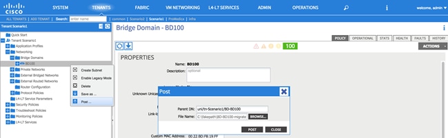
All of the VMs are now on the ACI-managed DVS, and the GW is now on the ACI fabric.
Figure 114: Scenario 1 Migrate Gateway from the FabricPath Domain to ACI Fabric
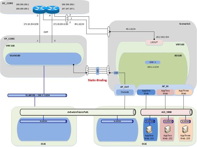
Validation
Now that you have moved the gateway functionality from the FabricPath domain to the ACI fabric, you will repeat all of the verification steps.
Figure 115: Scenario 1 Migrate Host to ACI – AppOneWeb
IFCONFIG::
cisco@AppOneWeb:~$ ifconfig eth0
eth0 Link encap:Ethernet HWaddr 00:50:56:82:bd:bf
inet addr:100.1.1.101 Bcast:100.1.1.255 Mask:255.255.255.0
inet6 addr: fe80::250:56ff:fe82:bdbf/64 Scope:Link
UP BROADCAST RUNNING MULTICAST MTU:1500 Metric:1
RX packets:25 errors:0 dropped:3 overruns:0 frame:0
TX packets:75 errors:0 dropped:0 overruns:0 carrier:0
collisions:0 txqueuelen:1000
RX bytes:2204 (2.2 KB) TX bytes:10778 (10.7 KB)
cisco@AppOneWeb:~$
In the following example, note that the ARP still shows the same MAC for the default Gateway. This is because the MAC address on BD100 on the fabric was changed to mimic the vMAC address from the HSRP configuration on the old FabricPath environment.
Figure 120: Scenario 1 Migrate Host to ACI – AppOneWeb ARP Validation
ARP –A:
cisco@AppOneWeb:~$ arp –a
? (100.1.1.102) at 00:50:56:82:d4:69 [ether] on eth0
? (100.1.1.103) at 00:50:56:82:d5:05 [ether] on eth0
? (100.1.1.1) at 00:00:0c:07:ac:64 [ether] on eth0
cisco@AppOneWeb:~$
Figure 121: Scenario 1 Migrate Host to ACI – AppOneWeb Ping Validation
PING::
cisco@AppOneWeb:~$ ping 100.1.1.1 -c 1
PING 100.1.1.1 (100.1.1.1) 56(84) bytes of data.
64 bytes from 100.1.1.1: icmp_seq=1 ttl=63 time=0.218 ms
--- 100.1.1.1 ping statistics ---
1 packets transmitted, 1 received, 0% packet loss, time 0ms
rtt min/avg/max/mdev = 0.218/0.218/0.218/0.000 ms
cisco@AppOneWeb:~$
cisco@AppOneWeb:~$ ping 100.1.1.102 -c 1
PING 100.1.1.102 (100.1.1.102) 56(84) bytes of data.
64 bytes from 100.1.1.102: icmp_seq=1 ttl=64 time=0.285 ms
--- 100.1.1.102 ping statistics ---
1 packets transmitted, 1 received, 0% packet loss, time 0ms
rtt min/avg/max/mdev = 0.285/0.285/0.285/0.000 ms
cisco@AppOneWeb:~$
cisco@AppOneWeb:~$ ping 100.1.1.103 -c 1
PING 100.1.1.103 (100.1.1.103) 56(84) bytes of data.
64 bytes from 100.1.1.103: icmp_seq=1 ttl=64 time=0.163 ms
--- 100.1.1.103 ping statistics ---
1 packets transmitted, 1 received, 0% packet loss, time 0ms
rtt min/avg/max/mdev = 0.163/0.163/0.163/0.000 ms
cisco@AppOneWeb:~$
cisco@AppOneWeb:~$ ping 199.199.199.1 -c 1
PING 199.199.199.1 (199.199.199.1) 56(84) bytes of data.
64 bytes from 199.199.199.1: icmp_seq=1 ttl=253 time=0.577 ms
--- 199.199.199.1 ping statistics ---
1 packets transmitted, 1 received, 0% packet loss, time 0ms
rtt min/avg/max/mdev = 0.577/0.577/0.577/0.000 ms
cisco@AppOneWeb:~$
Figure 122: Scenario 1 Migrate Host to ACI – AppOneWeb Traceroute Validation
TRACEROUTE::
cisco@AppOneWeb:~$ traceroute 100.1.1.1
traceroute to 100.1.1.1 (100.1.1.1), 30 hops max, 60 byte packets
1 100.1.1.1 (100.1.1.1) 0.774 ms 0.845 ms 0.955 ms
cisco@AppOneWeb:~$
cisco@AppOneWeb:~$ traceroute 199.199.199.1
traceroute to 199.199.199.1 (199.199.199.1), 30 hops max, 60 byte packets
1 100.1.1.1 (100.1.1.1) 0.381 ms 0.528 ms 0.683 ms
2 100.1.1.1 (100.1.1.1) 0.839 ms 1.038 ms 1.145 ms
3 199.199.199.1 (199.199.199.1) 1.183 ms 1.257 ms 1.357 ms
cisco@AppOneWeb:~$
Figure 116: Scenario 1 Validation – FabricPath domain
SHOW MAC ADDRESS-TABLE::
FP_Core01# show mac address-table address 0050.5682.bdbf
Note: MAC table entries displayed are getting read from software.
Use the 'hardware-age' keyword to get information related to 'Age'
Legend:
* - primary entry, G - Gateway MAC, (R) - Routed MAC, O - Overlay MAC
age - seconds since last seen,+ - primary entry using vPC Peer-Link,
(T) - True, (F) - False , ~~~ - use 'hardware-age' keyword to retrieve age info
VLAN MAC Address Type age Secure NTFY Ports/SWID.SSID.LID
---------+-----------------+--------+---------+------+----+------------------
* 100 0050.5682.bdbf dynamic ~~~ F F Po11
FP_Core01#
In the figure below, note that there are no more ARP entries in the FabricPath environment. This is a consequence of having shut down the SVIs for VLAN 100 on the FP spines.
Figure 124: Scenario 1 Migrate Host to ACI – FabricPath Core ARP Validation
SHOW IP ARP::
FP_Core01# show ip arp 100.1.1.101
Flags: * - Adjacencies learnt on non-active FHRP router
+ - Adjacencies synced via CFSoE
# - Adjacencies Throttled for Glean
D - Static Adjacencies attached to down interface
IP ARP Table
Total number of entries: 0
Address Age MAC Address Interface
FP_Core01#
In the figure below, note that the routing table for FabricCore01 looks different. You can now learn the 100.1.1.0/24 network via OSPF from DCCORE01/02 (it is not a directly connected IP subnet anymore).
Figure 125: Scenario 1 Migrate Host to ACI – FabricPath Core Routing Table Validation
SHOW IP ROUTE::
FP_Core01# show ip route 100.1.1.0/24
IP Route Table for VRF "default"
'*' denotes best ucast next-hop
'**' denotes best mcast next-hop
'[x/y]' denotes [preference/metric]
'%<string>' in via output denotes VRF <string>
100.1.1.0/24, ubest/mbest: 2/0
*via 172.19.254.2, Eth3/5, [110/20], 00:00:21, ospf-3369, type-2
*via 172.19.254.6, Eth3/6, [110/20], 00:00:21, ospf-3369, type-2
FP_Core01#
Figure 126: Scenario 1 Validation – ACI Fabric
SHOW ENDPOINT::
Leaf1# show endpoint ip 100.1.1.101
Legend:
O - peer-attached H - vtep a - locally-aged S - static
V - vpc-attached p - peer-aged L - local M - span
s - static-arp B - bounce
+-------------------+---------------+-----------------+--------------+-------------+
VLAN/ Encap MAC Address MAC Info/ Interface
Domain VLAN IP Address IP Info
+-------------------+---------------+-----------------+--------------+-------------+
25 vlan-1006 0050.5682.bdbf LV po13
Scenario1:VRF100 vlan-1006 100.1.1.101 LV
Leaf1#
Figure 127: Scenario 1 Migrate Host to ACI – ACI Fabric Routing Table Validation
SHOW IP ROUTE::
Leaf1# show ip route vrf Scenario1:VRF100 100.1.1.0/24
IP Route Table for VRF "Scenario1:VRF100"
'*' denotes best ucast next-hop
'**' denotes best mcast next-hop
'[x/y]' denotes [preference/metric]
'%<string>' in via output denotes VRF <string>
100.1.1.0/24, ubest/mbest: 1/0, attached, direct, pervasive
*via 10.0.40.65%overlay-1, [1/0], 6d04h, static
recursive next hop: 10.0.40.65/32%overlay-1
Leaf1#
Fabric Optimization
The final step (once all servers have been migrated from the FabricPath environment to the ACI fabric) is to enable Optimized Layer 2 forwarding on the bridge domain.
· Optimized forwarding of unknown Layer 2 unicast packets removes the needless flooding of unknown unicast packets on the bridge domain. If the Layer 2 destination of a packet is not known to the fabric, it is discarded by the ACI spines (the ACI leaf nodes by default send the traffic to the spines when they don’t know how to reach the destination).
· Disabling ARP flooding reduces the amount of broadcast packets on the bridge domain. ARP requests are sent in unicast mode by the fabric to known destinations as opposed to flooding.
· Changing the multidestination flooding to “Flood in Encapsulation” ensures that all broadcast level packets are flooded inside of the EPG encapsulation, and not at the bridge domain level.
Note: It is important to clarify that “Flood in Encapsulation” it is not synonymous of “Flood in EPG”. As previously mentioned, it is possible to associate a different VLAN ID tag to the same EPG on separate physical interfaces (on the same leaf or across separate leaf nodes). The “Flood in Encapsulation” option ensures that traffic is flooded to all the interfaces that are mapped to the same EPG and use the same VLAN encapsulation.
Table 26: Scenario 1 Forwarding Semantics
| Forwarding Semantics |
Configuration |
| Layer 2 Unknown Unicast |
Hardware Proxy |
| Layer 2 Unknown Multicast Flooding |
Flood |
| Multidestination Flooding |
Flood in Encapsulation |
| Unicast Routing |
Enabled |
| Enforce subnet check for IP learning |
Enabled |
| ARP Flooding |
Disabled |
Now any links to the FabricPath environment can be deleted. Before ACI, there were servers from an assortment of applications on the same broadcast domain (VLAN100), which caused many problems for security compliance. Now with ACI, the IP addressing can be maintained for the servers, while ensuring that they cannot talk to each other unless allowed via contracts.
Figure 128: Scenario 1 Final State after the Migration is Complete
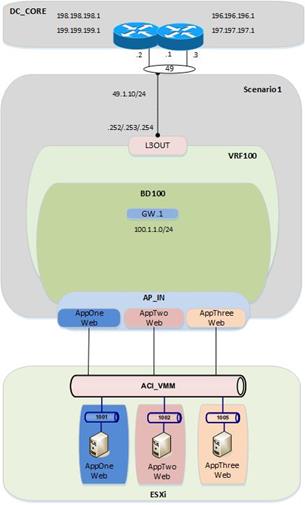
Migration Scenario 2
After completing the discussion for the migration Scenario 1, it is now time to discuss a second use case. The main differences between Scenario 1 and Scenario 2 are the following:
· The applications that are migrated between the FP and the ACI networks are already deployed into isolated VLANs/VRFs also in the FP network. That logical isolation must be maintained when relocating them to the ACI fabric.
· FW services nodes are deployed in the FP fabric to ensure every communication between different applications belonging to separate VRFs is subject to the FW security policy enforcement. The same behavior must be maintained after migrating the applications to the ACI fabric, so a pair of FWs is connected to the fabric to control inter-VRF and north-south traffic flows.
For the rest, the design looks quite similar, including the use of vPC logical connections to establish Layer 2 and Layer 3 connectivity between the FP and ACI domains. As it has been the case for Scenario 1, the following sections discuss in detail the various configuration steps, dividing them between infrastructure and tenant configurations specific to Scenario 2.
1. Fabric Access Policy Configuration
a. Static VLAN Pool
b. Physical Domain
c. External Routed Domain that will be used to create the L3Out connections between different VRFs in the ACI fabric and the ASA FWs.
2. Tenant Configuration for Scenario 2
a. Tenant creation (named “Scenario 2”)
b. Private Networks (i.e., VRF210, VRF211 and VRF212; these VRFs will map to the appropriate VRFs in the FabricPath domain)
c. Bridge Domains (i.e., BD210, BD211, BD212; these will map to the appropriate VLANs in the FabricPath domain)
d. Application Profiles and EPGs (i.e., Application Profiles APP1 and Outside)
i. EPG Outside
ii. EPG AppOneWeb
iii. EPG AppTwoWeb
iv. EPG Middleware
e. Layer 3 Connectivity (ASA FW to DCCORE01/02)
Note: The APIC GUI screenshots shown for each configuration step in Scenario 1 will not be repeated in the following sections, as they are essentially identical. Please refer to Scenario 1 for more details.
Figure 129: Scenario 2 ACI Design
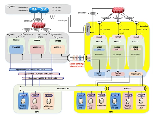
Fabric Access Policy Configuration
Static VLAN Pool
A static VLAN pool (vlanPool_Scenario2) needs to be created for Scenario 2 with the following encap blocks:
· “Outside_EPG” Encap Block: defines the VLAN tag that is going to be used on the Layer 2 vPC connections to the ASA outside interface and to the DC core devices (associated to the “Outside” EPG). From a Layer 3 point of view, the static routing information configured on the ASA FW points directly to the HSRP VIP address of the DC core devices as next hop, so the ACI fabric only performs Layer 2 transport functionalities in this case. This is different from what discussed in Scenario 1 where the ASA was not present and the ACI Fabric was connecting at Layer 3 to the DC core devices via the definition of a dedicated L3Out connection.
· “Layer 2” Encap Block: defines the set of VLANs used to establish Layer 2 connectivity between the FP and the ACI networks. As previously shown in Figure 129, VLANs 210, 211, and 212 are carried between the networks for establishing end-to-end Layer 2 communication.
· “Layer 3” Encap Block: defines the set of VLANs to be used to establish Layer 3 connectivity between each application (part of a dedicated VRF) and the ASA FW. A dedicated L3Out for each application will be defined for this purpose.
Table 27: Scenario 2 Static VLAN Pool
| VLAN Pool |
Configuration |
Description |
| Name |
vlanPool_Scenario2 |
- |
| Allocation Mode |
Static Allocation |
- |
| Encap Block |
502 200-212 600-612 |
Outside_EPG Layer 2 Layer 3 |
To configure the Static VLAN Pool, log in to the APIC GUI with administrator privileges and follow the path below:
Fabric à Access Policies à Pools à VLAN à [vlanPool_Scenario2]
Figure 130: Scenario 2 Static VLAN Pool
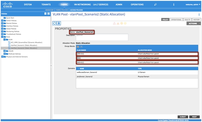
XML 35: Scenario 2 Static VLAN Pool
<fvnsVlanInstP allocMode="static" descr="" dn="uni/infra/vlanns-[vlanPool_Scenario2]-static" name="vlanPool_Scenario2" >
<fvnsEncapBlk allocMode="inherit" descr="" from="vlan-200" name="" to="vlan-212"/>
<fvnsEncapBlk allocMode="inherit" descr="" from="vlan-502" name="" to="vlan-502"/>
<fvnsEncapBlk allocMode="inherit" descr="" from="vlan-600" name="" to="vlan-612"/>
</fvnsVlanInstP>
Physical Domain
As already discussed for Scenario 1, a physical domain is defined to allow connectivity from the ACI fabric to the VMs that have not yet been migrated and are still connected to the FP network, as well as to the VMs that have been migrated to the ACI fabric but are still connected to the vCenter-managed DVS.
Note: In multitenant deployments, a separate physical domain will likely be created for each tenant. This allows to granularly manage resources associated with each tenant.
Table 28: Scenario 2 Physical Domain
| Physical Domain |
Configuraiton |
| Name |
phyDomain_Scenario2 |
| VLAN Pool |
vlanPool_Scenario2 |
To configure the physical domain, log in to the APIC GUI with administrator privileges and follow the path below:
Fabric à Access Policies à Physical and External Domains à Physical Domains à [phyDomain_Scenario2]
External Routed Domain
In this section, use the following details to create an external routed domain and associate with the VLAN pool created earlier. The VLANs specified in the encapsulation blocks previously discussed will be used for both connecting the ACI fabric to the DC core devices and to connect each internal VRF to the ASA FW.
Table 29: Scenario2 External Routed Domain
| External Routed Domain |
Configuration |
| Name |
extRoutedDomain_Scenario2 |
| VLAN Pool |
vlanPool_Scenario2 |
To configure the external routed domain, log in to the APIC GUI with administrator privileges and follow the path below:
Fabric à Access Policies à Physical and External Domains à External Routed Domain à [extRoutedDomain_Scenario2]
Tenant Configuration
Note: The use of the Quick Start guide is not used in order to demonstrate the object relationship for the configuration parameters. Additionally, while Quick Start menus can change from version to version, the method of configuration displayed in this document will not change.
Tenant
A second tenant {Scenario2) is created in this case. Notice that the different applications migrated to the ACI fabric will be part of their own dedicated VRF. However, all the VRFs are considered part of the same tenant.
Table 30: Scenario 2 Tenant
| Tenant |
Configuration |
| Name |
Scenario2 |
Note: A tenant represents a unit of isolation from a policy perspective and can represent a customer, an organization, or domain in an enterprise setting, or just a convenient grouping of policies.
To configure the Tenant, log in to the APIC GUI with administrator privileges and follow the path below:
Tenants à ADD TENANT à [Create Tenant Scenario2]
Private Networks
For Scenario 2, you will need to configure a total of four private networks (VRFs). The first three VRFs will match the existing FabricPath environment (VRF210, VRF211, and VRF212), and the final VRF will be used to provide Layer 3 connectivity between the FW and the DC core switches.
Table 31: Scenario 2 Private Networks
| Private Network |
Configuraiton |
| VRF210 |
Unenforced |
| VRF211 |
Unenforced |
| VRF212 |
Unenforced |
| Outside |
Unenforced |
Differently from Scenario 1, you will be selecting “unenforced” policy control for each defined private network. This essentially turns the ACI fabric into a router, without the need to define Contracts to establish communication between EPGs. You have selected this configuration for Scenario 2 because by design all inter-VRF communication is subject to the security enforcement applied by the stateful ASA FW.
To configure the private network, log in to the APIC GUI with administrator privileges and follow the path below:
Tenants à [Scenario2] à Networking à Private Networks à [Create VRF210]
Tenants à [Scenario2] à Networking à Private Networks à [Create VRF211]
Tenants à [Scenario2] à Networking à Private Networks à [Create VRF212]
Tenants à [Scenario2] à Networking à Private Networks à [Create Outside]
Bridge Domains
Different bridge domains need to be created in Scenario 2 to extend the Layer 2 broadcast domains between the FP and the ACI networks. This is because of the design choice of mapping each VLANs used in the FP network to a dedicated BD and EPG on the ACI fabric (VLAN = EPG = BD).
All the bridge domains are characterized by the same configuration parameters shown in the tables below and already discussed when creating the bridge domain for the previously discussed Scenario 1.
Table 32: Scenario 2 Bridge Domain BD210
| Bridge Domain |
Configuration |
| Name |
BD210 |
| Private Network |
Scenario2/VRF210 |
| Layer 2 Unknown Unicast |
Flood |
| Layer 2 Unknown Multicast Flooding |
Flood |
| Multi Destination Flooding |
Flood within BD |
| Unicast Routing |
Enabled |
| ARP Flooding |
Enabled |
| Enforce subnet check for IP learning |
Enabled |
Table 33: Scenario 2 Bridge Domain BD211
| Bridge Domain |
Configuration |
| Name |
BD211 |
| Private Network |
Scenario2/VRF211 |
| Layer 2 Unknown Unicast |
Flood |
| Layer 2 Unknown Multicast Flooding |
Flood |
| Multi Destination Flooding |
Flood within BD |
| Unicast Routing |
Enabled |
| ARP Flooding |
Enabled |
| Enforce subnet check for IP learning |
Enabled |
Table 34: Scenario 2 Bridge Domain BD212
| Bridge Domain |
Configuration |
| Name |
BD212 |
| Private Network |
Scenario2/VRF212 |
| Layer 2 Unknown Unicast |
Flood |
| Layer 2 Unknown Multicast Flooding |
Flood |
| Multi Destination Flooding |
Flood within BD |
| Unicast Routing |
Enabled |
| ARP Flooding |
Enabled |
| Enforce subnet check for IP learning |
Enabled |
To configure the Bridge Domains, log in to the APIC GUI with administrator privileges and follow the path below:
Tenants à [Scenario2] à Networking à Bridge Domains à [Create BD210]
Tenants à [Scenario2] à Networking à Bridge Domains à [Create BD211]
Tenants à [Scenario2] à Networking à Bridge Domains à [Create BD212]
Bridge Domain Subnets
Each bridge domain will be associated to a dedicated private network (VRF) and route traffic for its IP subnet, as highlighted in the tables below.
Table 35: Scenario 2 Bridge Domain Subnet
| Bridge Domain Subnet |
Configuration |
Description |
| Subnet |
210.1.1.254/24 |
Pervasive Gateway |
| Scope |
Public |
- |
Table 36: Scenario 2 Bridge Domain Subnet
| Bridge Domain Subnet |
Configuration |
Description |
| Subnet |
211.1.1.254/24 |
Pervasive Gateway |
| Scope |
Public |
- |
Table 37: Scenario 2 Bridge Domain Subnet
| Bridge Domain Subnet |
Configuration |
Description |
| Subnet |
212.1.1.254/24 |
Pervasive Gateway |
| Scope |
Public |
- |
Notice how the IP address associated to each Bridge Domain (.254) is temporary used until the default gateway is migrated from the FP spines to the ACI fabric.
To configure the bridge domain subnet, log in to the APIC GUI with administrator privileges and follow the path below:
Tenants à [Scenario2] à Networking à Bridge Domains à [BD210] à Subnets
Tenants à [Scenario2] à Networking à Bridge Domains à [BD211] à Subnets
Tenants à [Scenario2] à Networking à Bridge Domains à [BD212] à Subnets
Contract(s)
No contracts are needed for this scenario because you have selected “un-enforced” policy on all private networks (VRFs).
External Routed Networks
For Layer 3 connectivity to the outside world, each private network (VRF) will have a separate L3Out connection to a stateful ASA firewall, as previously shown in Figure 129. All communication between the VRFs on the ACI fabric will have to leave the fabric on a given L3Out connection, be inspected by the firewall, and then return through a second L3Out connection.
Requirements:
· Each VRF on the ACI fabric will have a 0.0.0.0/0 route from each border leaf pointing to each respective FW GW address for that VRF.
· The FW will have static routes pointing to the internal ACI subnets for the respective VRFs.
· The FW will also use a 0.0.0.0/0 route pointing to the HSRP VIP address on the DC core devices to establish communication with the external Layer 3 domain.
In order to provide a resilient solution, the deployment of a pair of ASA FWs is recommended, working in Active/Standby mode. This implies that the ACI fabric needs to connect via vPC logical connections to both ASA nodes, as shown in figure below. This requires a specific L3Out configuration discussed below.
Figure 131: ACI Fabric Connecting to an Active/Standby ASA FW Pair
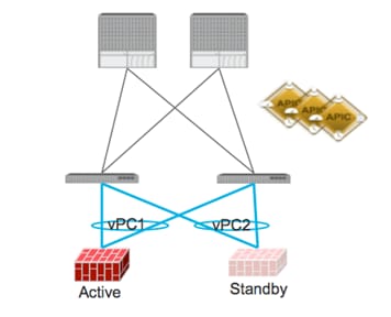
In order to complete the configuration of the required L3Outs, the following steps are required:
1. Configure L3Out Properties
2. Configure Logical Node Profiles
3. Configure Logical Interface Profiles
4. Configure L3Out EPG parameters
Note: As previously mentioned, three L3Out connections are required to interconnect each VRF to the SA FW. The following sections provide the configuration required for one of them, since the other two would be similar.
Step 1 – L3Out Properties
In this section the L3Out connection, named “L3OUT_AppOneWeb”, will be created. The L3Out will define the network details for reaching networks outside of the fabric. The configuration details for this L3Out connection are described in Table 38
AppOneWeb
Table 38: Scenario 2 L3OUT_AppOneWeb Properties
| L3OUT |
Configruation |
Description |
| Name |
L3OUT_AppOneWeb |
- |
| Private Network |
Scenario2/VRF210 |
Associate the L3Out with the proper Private Network |
| External Routed Domain |
extRoutedDomain_Scenario2 |
Associate the L3Out with the proper External Routed Domain (this is a domain that contains Vlans, which can be used by the L3Out for connectivity (SVI-based, etc.). |
To configure the external routed network, log in to the APIC GUI with administrator privileges and follow the path below:
Tenants à [Scenario2] à Networking à External Routed Networks à [Create L3OUT_AppOneWeb]
Repeat the steps above for both AppTwoWeb and Middleware using VRF211 and VRF212 respectively.
Step 2 – Create Node Profile
In this section, the external routed network node profile will be created. The node profile will define fabric nodes that will participate in the L3Out connectivity and provide the static route. A single logical node profile will be created, including the two physical border leaf nodes and the static route that will be added for each node. The static route will point to the IP address of the ASA interface used for this specific VRF.
Table 39: Scenario 2 Node Profile
| Node Profile |
Configuration |
Description |
| Name |
Leaf1_2_Node_Profile |
- |
| Node ID |
topology/pod-1/node-101 |
- |
| Router ID |
100.100.100.100 |
(This needs to be a unique IP address which is NOT in use). The ACI fabric will automatically create a loopback on the associated border leaf with this IP. |
| Static Route |
0.0.0.0/0 |
100.110.0.4 |
| Node ID |
topology/pod-1/node-102 |
- |
| Router ID |
200.200.200.200 |
(This needs to be a unique IP address which is NOT in use). The ACI Fabric will automatically create a loopback on the associated border leaf with this IP. |
| Static Route |
0.0.0.0/0 |
100.110.0.4 |
To configure the node profiles, log in to the APIC GUI with administrator privileges and follow the path below:
Tenants à [Scenario2] à Networking à External Routed Networks à [L3OUT_AppOneWeb] à Logical Node Profiles à [Create Node_Profile]
Step 3 - Interface Profiles Creation
As previously mentioned, two vPC logical connections are defined in this Scenario 2 to ensure connectivity between the ACI fabric and the ASA FW nodes (Active and Standby). Both vPC connections must be associated to the same L3Out connection, as they will both be used depending which FW node is running as active.
Table 40: Scenario 2 Interface Profile 1
| Interface Profile |
Configuration |
Description |
| Name |
Leaf1_2_Int_Profile_1 |
- |
| Interface Type |
SVI |
- |
| Path Type |
Virtual Port Channel |
- |
| Path |
Node101-102/policyGrpVPC_ASA_IN_1 |
vPC to the Active ASA Node |
| Encap |
Vlan-610 |
- |
| Site A IP Address |
100.110.0.2/24 |
- |
| Site A Secondary IP Address |
100.110.0.1/24 |
The secondary IP address for each Site A MUST match Site B |
| Site B IP Address |
100.110.0.3/24 |
- |
| Site B Secondary IP Address |
100.110.0.1/24 |
The secondary IP address for each Site A MUST match Site B |
| MTU |
9000 |
By default the fabric will “inherit” the system MTU, which is 9000. It is considered best practice to manually set the fabric MTU on your interface profile to match the device on the other side. |
Table 41: Scenario 2 Interface Profile 2
| Interface Profile |
Configuration |
Description |
| Name |
Leaf1_2_Int_Profile_2 |
- |
| Interface Type |
SVI |
- |
| Path Type |
Virtual Port Channel |
- |
| Path |
Node101-102/policyGrpVPC_ASA_IN_2 |
vPC to the Standby ASA Node |
| Encap |
Vlan-610 |
- |
| Site A IP Address |
100.110.0.2/24 |
- |
| Site A Secondary IP Address |
100.110.0.1/24 |
The secondary IP address for each Site A MUST match Site B |
| Site B IP Address |
100.110.0.3/24 |
- |
| Site B Secondary IP Address |
100.110.0.1/24 |
The secondary IP address for each Site A MUST match Site B |
| MTU |
9000 |
By default the fabric will “inherit” the system MTU, which is 9000. It is considered best practice to manually set the fabric MTU on your interface profile to match the router on the other side. |
To configure the interface profiles, log in to the APIC GUI with administrator privileges and follow the path below:
Tenants à [Scenario2] à Networking à External Routed Networks à [L3OUT_AppOneWeb] à Logical Node Profiles à [Leaf1_2_Node_Profile] à Logical Interface Profiles à [Create Interface_Profiles]
Step 4 – Create L3Out EPG (External Network)
The L3Out External Network (aka External EPG) configured define the external IP prefixes capable of accessing fabric resources within the tenant. External EPGs are defined using IP prefix and mask. More than one external EPGs may be configured, depending if different policies need to be applied to these external EPGs (IP prefixes).
Contracts will be needed to allow communication to occur between internal EPGs on the Private Network (VRF) and the external EPGs associated to the L3Out. Without contract, all connectivity from outside is blocked and external routes will not be learnt when using a dynamic routing protocol.
Table 42: Scenario 2 External EPG
| EPG |
Configuration |
Description |
| Name |
L3EPG |
- |
| Subnet |
0.0.0.0/0 |
Defines the external subnets/networks that will be allowed to communicate with resources internal to the fabric (assuming a contract will be added as well). |
| Scope |
Security Import Subnet |
The use of the scope and subnet field allows for the control of traffic coming into the fabric. The field has other functions that are not required to support the use case discussed. |
To configure the external EPG, log in to the APIC GUI with administrator privileges and follow the path below:
Tenants à [Scenario2] à Networking à External Routed Networks à [L3OUT_AppOneWeb] à Networks à [L3EPG]
Step 5 – Provide a Contract for the Layer 3 EPG
In this section under the contracts tab for the L3EPG, provide the L3Out contract (the Permit any any), which was previously created, to ensure successful connectivity between the fabric and the external Layer 3 network domain.
Table 43: Scenario 2 External EPG Provider Contract
| Provider Contracts |
Configuration |
Description |
| Name |
L3OUT_Permit_Any |
- |
To configure the contract filter association, login to the APIC GUI with administrator privileges and follow the path below:
Tenants à [Scenario2] à Networking à External Routed Networks à [L3OUT_AppOneWeb] à Networks à [L3EPG]
Under the contracts tab for the L3EPG, provide the L3Out contract (the Permit any any), which was previously created.
Integration Phase – Scenario 2
Next is the Integration Phase. Now that the ACI fabric has been staged, you are going to begin the configuration sections in ACI where you will be establishing connectivity to the FabricPath environment via the vPCs.
Figure 132: Scenario 2 Integration Phase
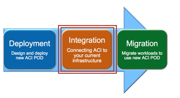
Application Profiles and EPGs
For Scenario 2, you will create two application profiles; one called APP1, which will house the EPGs where to migrate the endpoints initially connected to the FP VLANs, and one called Outside, which act as a Layer 2 only EPG for establishing Layer 3 connectivity between the FW and the DC core routers.
Figure 133: Scenario 2 Application Profile
| |
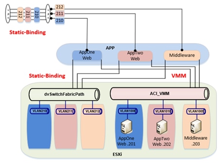
Application Profile APP1
For Scenario 2, application profile APP1 will contain the EPGs for the newly managed applications migrated from the FabricPath domain.
Table 44: Scenario 2 Application Profile APP1
| Application Profile |
Configuration |
Description |
| Name |
APP1 |
- |
To configure the application profile, log in to the APIC GUI with administrator privileges and follow the path below:
Tenants à [Scenario2] à Application Profile à [APP1]
EPG AppOneWeb
In this section, use the information in the table below to create the endpoint group AppOneWeb within the previously created application profile.
Table 45: Scenario 2 EPG AppOneWeb
| EPG |
Bridge Domain |
Domain |
| AppOneWeb |
BD210 |
phyDomain_Scenario2 and VMware/ACI_VMM |
Note that the EPG AppOneWeb (and this applies also to the other EPGs discussed in the following sections) is associated to both previously created Physical Domain (phyDomain_Scenario2) and VMM Domain (ACI_VMM). This is required because the workloads migrated to the ACI fabric will be first connected to the vCenter managed DVS (hence seen as physical hosts in ACI) and successively moved to the ACI-managed DVS (therefore becoming part of the VMM domain).
To configure the EPG AppOneWeb, log in to the APIC GUI with administrator privileges and follow the path below:
Tenants à [Scenario2] à Application Profile à [APP1] à Application EPGs à [AppOneWeb]
EPG AppTwoWeb
In this section, use the information in the table below to create the endpoint group AppTwoWeb within the previously created application profile.
Table 46: Scenario 2 EPG AppTwoWeb
| EPG |
Bridge Domain |
Domain |
| AppTwoWeb |
BD211 |
phyDomain_Scenario2 and VMware/ACI_VMM |
To configure the EPG AppOneWeb, log in to the APIC GUI with administrator privileges and follow the path below:
Tenants à [Scenario2] à Application Profile à [APP1] à Application EPGs à [AppTwoWeb]
EPG Middleware
In this section, use the information in the table below to create the endpoint group Middleware within the previously created application profile.
Table 47: Scenario 2 EPG Middleware
| EPG |
Bridge Domain |
Domain |
| Middleware |
BD212 |
phyDomain_Scenario2 and VMware/ACI_VMM |
To configure the EPG AppOneWeb, log in to the APIC GUI with administrator privileges and follow the path below:
Tenants à [Scenario2] à Application Profile à [APP1] à Application EPGs à [MiddleWare]
Static Binding for APP1 EPGs
In this section, use the information in the following table to create the static bindings for the APP1 EPGs. The static bindings would serve two purposes:
· Providing L2 connectivity to the endpoints that are still connected to the FabricPath network. For this to happen, the static binding will be performed with the Layer 2 vPC logical connection to the FP spines.
· Connecting endpoints to the previously created AppOneWeb, AppTwoWeb, and Middleware EPGs. Those endpoints are VMs still connected to the vSphere managed DVS but migrated on the ESXi hosts part of the UCSB-Mini chassis connected to the ACI leaf nodes via FIs.
Table 48: Scenario 1 APP1 EPGs Statis Bindings
| EPG |
Path |
Encap |
| AppOneWeb |
Node-101-102/policyGrpVPC_FI_A |
vlan-210 |
| AppOneWeb |
Node-101-102/policyGrpVPC_FI_B |
vlan-210 |
| AppOneWeb |
Node-101-102/policyGrpVPC_FPCORE |
vlan-210 |
| AppTwoWeb |
Node-101-102/policyGrpVPC_FI_A |
vlan-211 |
| AppTwoWeb |
Node-101-102/policyGrpVPC_FI_B |
vlan-211 |
| AppTwoWeb |
Node-101-102/policyGrpVPC_FPCORE |
vlan-211 |
| Middleware |
Node-101-102/policyGrpVPC_FI_A |
vlan-212 |
| Middleware |
Node-101-102/policyGrpVPC_FI_B |
vlan-212 |
| Middleware |
Node-101-102/policyGrpVPC_FPCORE |
vlan-212 |
To configure Static Bindings, log in to the APIC GUI with administrator privileges and follow the path below:
Tenants à [Scenario2] à Application Profileà [APP1] à Application EPGs à [AppOneWeb] à Static Bindings
Tenants à [Scenario2] à Application Profileà [APP1] à Application EPGs à [AppTwoWeb] à Static Bindings
Tenants à [Scenario2] à Application Profileà [APP1] à Application EPGs à [Middleware] à Static Bindings
Application Profile Outside
For Scenario 2, the application profile Outside is used to provide Layer 2 connectivity between the FW and the DC core devices.
Table 48: Scenario 2 Application Profile Outside
| Application Profile |
Configruation |
Description |
| Name |
Outside |
- |
To configure the Application Profile, log in to the APIC GUI with administrator privileges and follow the path below:
Tenants à [Scenario2] à Application Profile à [Outside]
EPG Outside
In this section, use the information in the table below to create the endpoing group Outside within the previously created application profile.
Table 49: Scenario 2 EPG Outside
| EPG |
Bridge Domain |
Domain |
| Outside |
Outside |
phyDomain_Scenario2 |
The EPG Outside is only associated to the Physical Domain as it is used to connect the FW and the DC core devices that represent physical endpoints.
To configure the EPG AppOneWeb, log in to the APIC GUI with administrator privileges and follow the path below:
Tenants à [Scenario2] à Application Profile à [Outside] à Application EPGs à [Outside]
Static Binding for EPG Outside
In this section, use the information in the table below to create the static bindings for the EPG Outside. The static bindings will allow connecting endpoints to the previously created EPG Outside. Those endpoints are the ASA FW nodes (their outside interfaces) and the DC Core devices. As previously mentioned, the Outside EPG provides the Layer 2 connectivity allowing L3 communication between the ASA FWs and the DC core.
Table 50: Scenario 1 EPG Outside Static Bindings
| EPG |
Path |
Encap |
| Outside |
Node-101-102/policyGrpVPC_ASA_OUT |
vlan-502 |
| Outside |
Node-101-102/policyGrpVPC_DCCORE |
vlan-502 |
To configure Static Bindings, log in to the APIC GUI with administrator privileges and follow the path below:
Tenants à [Scenario2] à Application Profileà [AP_Outside] à Application EPGs à [Outside] à Static Bindings
Migration Phase – Scenario 2
Now that Layer 2 and Layer 3 connectivity has been established between the ACI fabric and the FabricPath environment and the VM integration to vCenter is complete, it is time to start migrating the application endpoints from the FabricPath environment into the ACI fabric.
Figure 117: Scenario 2 Migration Phase

Applications within Scenario 2 are initially deployed in separate VLANs and associated routing tables (VRFs) in the FabricPath environment. The intent of the migration is to demonstrate a network-centric migration, where you map VRFs to ACI private networks and VLANs to EPGs / BDs.
Note: Although this topology is utilized as part of the migration efforts described herein, STP, vPC, or other topologies could leverage the overall strategy and process.
The migration plan includes the following steps detailed in the upcoming sections:
1. Premigration Validation: the intent of this step is to ensure that the current environment including applications is behaving as intended and will include confirmation of various connectivity checks.
2. Application Migration: this step will be accomplished by migrating the application within vCenter from the ESXi host connected to the FabricPath network to the ESXi host connected to the ACI Fabric using vMotion.
3. Port Group Migration: this step involves migrating the host VM vmnic from the vCenter managed DVS port group to the ACI managed DVS port group.
4. Gateway Migration: this step includes migrating the gateway and Layer 3 functionalities from the FabricPath domain to the ACI fabric.
5. Continue Server Migration: within this step of the migration, additional server migration efforts continue until the point where all applications/servers have been migrated from the FabricPath domain to the ACI fabric.
Figure 118: Scenario 2 Initial State in the FabricPath Domain
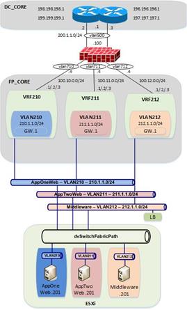
Premigration Validation
The following are some important premigration assumptions:
· All virtual hosts attached to the vCenter managed DVS are using the FabricPath Spines as their Layer 3 gateway. Layer 2 communication between the VMs and the default gateway is achieved by stretching the Layer 2 broadcast domains across the FP network and by trunking VLANs 210-212 from the FP leaf devices down to the UCS chassis where the ESXi host resides.
· All virtual hosts attached to the vCenter managed DVS exit the datacenter via static routing to the ASA FW and ultimately to the DC core switches.
· The ESXi host connected to the FabricPath domain has uplinks connected to the vCenter managed DVS (dvSwitchFabricPath)
· The ESXi host connected to the ACI Fabric has uplinks connected both to the vCenter managed DVS (dvSwitchFabricPath) and to the ACI managed DVS (ACI_VMM).
· All VMs are using shared storage (iSCSI), which is available for both the ESXi hosts in the FabricPath and ACI environments. This is what allows live vMotions to occur.
· Layer 2 connectivity from the FabricPath domain to the ACI fabric is successfully established via the Layer 2 vPC logical connection.
· The same Layer 2 broadcast domains are extended from the FabricPath network to the ACI fabric and allows Layer 2 connectivity between VMs deployed on the ESXi hosts connected to the FabricPath and ACI domains.
The figure below shows the application VM S2-AppOneWeb, which will be the first VM migrated from the FabricPath domain to the ACI fabric.
Figure 136: Scenario 2 AppOneWeb VM
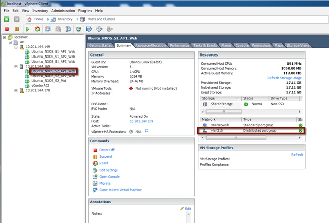
The figure below depicts the entire topology including the Layer 2 connectivity. AppOneWeb is initially connected to the vCenter managed DVS on the ESXi host in the FabricPath environment. Step 1 will consists in performing live migration (vMotion) for this host from the ESXi server in the FabricPath environment to the ESXi server in the ACI environment.
Figure 119: Scenario 2 Premigration Topology
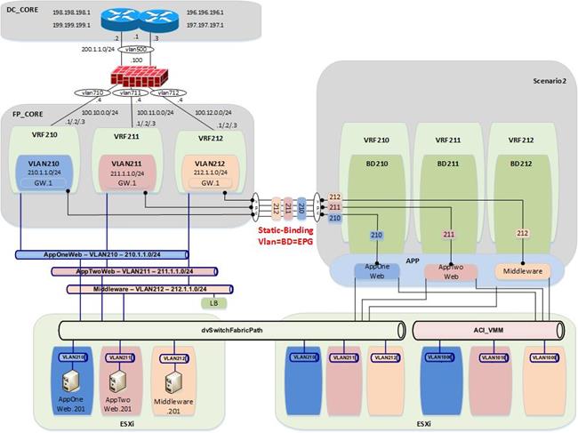
Validation
The initial validation step includes the following connectivity test from the host VM, S2-AppOneWeb. The first validation test ensures the correct interface on the VM has the required IP address and ARP entries. Connectivity confirmation via ping and traceroute allows for gateway and core reachability path and response test.
Figure 120: Scenario 2 Premigration Validation – AppOneWeb
IFCONFIG::
cisco@S2-AppOneWeb:~$ ifconfig eth0
eth0 Link encap:Ethernet HWaddr 00:50:56:9e:2a:60
inet addr:210.1.1.201 Bcast:210.1.1.255 Mask:255.255.255.0
inet6 addr: fe80::250:56ff:fe9e:2a60/64 Scope:Link
UP BROADCAST RUNNING MULTICAST MTU:1500 Metric:1
RX packets:186 errors:0 dropped:0 overruns:0 frame:0
TX packets:314 errors:0 dropped:0 overruns:0 carrier:0
collisions:0 txqueuelen:1000
RX bytes:12382 (12.3 KB) TX bytes:26071 (26.0 KB)
cisco@S2-AppOneWeb:~$
Figure 139: Scenario 2 Premigration Validation – AppOneWeb ARP Validation
ARP –A:
cisco@S2-AppOneWeb:~$ arp -a
? (210.1.1.2) at 38:ed:18:a2:f1:42 [ether] on eth0
? (210.1.1.1) at 00:00:0c:07:ac:d2 [ether] on eth0
? (210.1.1.3) at 38:ed:18:a2:f3:c2 [ether] on eth0
cisco@S2-AppOneWeb:~$
In the figure below, note that S2-AppOneWeb can ping its GW (210.1.1.1) as well as the loopback interface on DCCORE01 (199.199.199.1).
Figure 140: Scenario 2 Premigration Validation – AppOneWeb Ping Validation
PING::
cisco@S2-AppOneWeb:~$ ping 210.1.1.1 -c 1
PING 210.1.1.1 (210.1.1.1) 56(84) bytes of data.
64 bytes from 210.1.1.1: icmp_seq=1 ttl=255 time=1.04 ms
--- 210.1.1.1 ping statistics ---
1 packets transmitted, 1 received, 0% packet loss, time 0ms
rtt min/avg/max/mdev = 1.047/1.047/1.047/0.000 ms
cisco@S2-AppOneWeb:~$
cisco@S2-AppOneWeb:~$ ping 199.199.199.1 -c 1
PING 199.199.199.1 (199.199.199.1) 56(84) bytes of data.
64 bytes from 199.199.199.1: icmp_seq=1 ttl=254 time=0.808 ms
--- 199.199.199.1 ping statistics ---
1 packets transmitted, 1 received, 0% packet loss, time 0ms
rtt min/avg/max/mdev = 0.808/0.808/0.808/0.000 ms
cisco@S2-AppOneWeb:~$
Figure 141: Scenario 2 Premigration Validation – AppOneWeb Traceroute Validation
TRACEROUTE::
cisco@S2-AppOneWeb:~$ traceroute 210.1.1.1
traceroute to 210.1.1.1 (210.1.1.1), 30 hops max, 60 byte packets
1 210.1.1.1 (210.1.1.1) 3.327 ms 1.593 ms 1.692 ms
cisco@S2-AppOneWeb:~$
cisco@S2-AppOneWeb:~$ traceroute 199.199.199.1
traceroute to 199.199.199.1 (199.199.199.1), 30 hops max, 60 byte packets
1 210.1.1.3 (210.1.1.3) 0.620 ms 0.639 ms 210.1.1.2 (210.1.1.2) 0.997 ms
2 199.199.199.1 (199.199.199.1) 1.262 ms 2.905 ms 1.514 ms
cisco@S2-AppOneWeb:~$
The second validation step includes the following connectivity test from the FabricPath Cisco Nexus 7000 Switches. The MAC address and ARP entries are queried to ensure that the Cisco Nexus 7000 switches can see the S2-AppOneWeb VM.
In the figure below, note that the MAC address of AppOneWeb is 0050.569e.2a60 and 1122 is the FabricPath SwitchID of the access-layer Cisco Nexus 5600 to which the ESXi host is connected.
Figure 121: Scenario 2 Validation – FabricPath Domain
SHOW MAC ADDRESS-TABLE::
FP_Core01# show mac address-table address 00:50:56:9e:2a:60
Note: MAC table entries displayed are getting read from software.
Use the 'hardware-age' keyword to get information related to 'Age'
Legend:
* - primary entry, G - Gateway MAC, (R) - Routed MAC, O - Overlay MAC
age - seconds since last seen,+ - primary entry using vPC Peer-Link,
(T) - True, (F) - False , ~~~ - use 'hardware-age' keyword to retrieve age info
VLAN MAC Address Type age Secure NTFY Ports/SWID.SSID.LID
---------+-----------------+--------+---------+------+----+------------------
210 0050.569e.2a60 dynamic ~~~ F F 1122.0.0
FP_Core01#
Figure 143: Scenario 2 Validation – FabricPath Domain ARP Validation
SHOW IP ARP::
FP_Core01# show ip arp 210.1.1.201 vrf vrf210
Flags: * - Adjacencies learnt on non-active FHRP router
+ - Adjacencies synced via CFSoE
# - Adjacencies Throttled for Glean
D - Static Adjacencies attached to down interface
IP ARP Table
Total number of entries: 1
Address Age MAC Address Interface
210.1.1.201 00:01:38 0050.569e.2a60 Vlan210
FP_Core01#
Figure 144: Scenario 2 Validation – FabricPath Domain Routing Table Validation
SHOW IP ROUTE::
FP_Core01# show ip route 210.1.1.0 vrf vrf210
IP Route Table for VRF "vrf210"
'*' denotes best ucast next-hop
'**' denotes best mcast next-hop
'[x/y]' denotes [preference/metric]
'%<string>' in via output denotes VRF <string>
210.1.1.0/24, ubest/mbest: 1/0, attached
*via 210.1.1.2, Vlan210, [0/0], 02:45:58, direct
FP_Core01#
The third validation step includes the following connectivity test from the Brownfield. The endpoint connectivity and the route validation are used to confirm the endpoint discovery process and correct routing entry.
Note that you expect to see nothing from the ACI perspective during this test. The VM is still on the FabricPath attached ESXi host, and the gateway for VLAN 210 still resides in the FabricPath environment.
Figure 122: Scenario 2 Validation – ACI Fabric
SHOW ENDPOINT::
Leaf1# show endpoint ip 2100.1.1.201
Legend:
O - peer-attached H - vtep a - locally-aged S - static
V - vpc-attached p - peer-aged L - local M - span
s - static-arp B - bounce
+-------------------+---------------+-----------------+--------------+-------------+
VLAN/ Encap MAC Address MAC Info/ Interface
Domain VLAN IP Address IP Info
+-------------------+---------------+-----------------+--------------+-------------+
Leaf1#
Figure 146: Scenario 2 Validation – ACI FabricaPath Routing Table Validation
SHOW IP ROUTE::
Leaf1# show ip route vrf Scenario2:VRF210 210.1.1.0/24
IP Route Table for VRF "Scenario2:VRF210"
'*' denotes best ucast next-hop
'**' denotes best mcast next-hop
'[x/y]' denotes [preference/metric]
'%<string>' in via output denotes VRF <string>
210.1.1.0/24, ubest/mbest: 1/0, attached, direct, pervasive
*via 10.0.40.65%overlay-1, [1/0], 01w10d, static
recursive next hop: 10.0.40.65/32%overlay-1
Leaf1#
Application Migration
Now that you have established where the VM (S2-AppOneWeb) is, and where its gateway is (FabricPath spine), it’s time to send it into the ESXi host in the ACI fabric with a live vMotion.
Host Migrations
Following the vMotion event you can now see in the following figure that the host has been migrated to the ESXi host connected to the ACI fabric.
Figure 123: Scenario 2 Host Migration
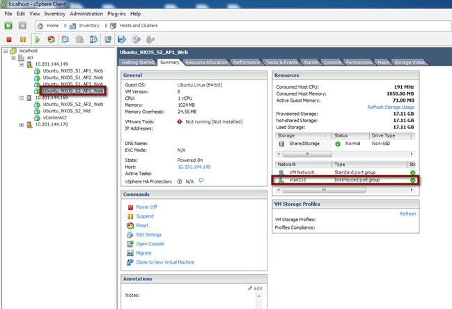
Figure 124: Scenario 2 vMotion Ping
Right before you initiate the vMotion from vCenter, you begin a ping to the gateway on the FabricPath spine. Two (2) packets are dropped during the vMotion.
cisco@S2-AppOneWeb:~$ ping 210.1.1.1
PING 210.1.1.1 (210.1.1.1) 56(84) bytes of data.
64 bytes from 210.1.1.1: icmp_seq=1 ttl=255 time=1.12 ms
64 bytes from 210.1.1.1: icmp_seq=2 ttl=255 time=1.19 ms
64 bytes from 210.1.1.1: icmp_seq=3 ttl=255 time=1.14 ms
64 bytes from 210.1.1.1: icmp_seq=4 ttl=255 time=1.16 ms
64 bytes from 210.1.1.1: icmp_seq=5 ttl=255 time=1.17 ms
64 bytes from 210.1.1.1: icmp_seq=8 ttl=255 time=1.17 ms
64 bytes from 210.1.1.1: icmp_seq=9 ttl=255 time=1.13 ms
64 bytes from 210.1.1.1: icmp_seq=10 ttl=255 time=1.20 ms
64 bytes from 210.1.1.1: icmp_seq=11 ttl=255 time=1.10 ms
64 bytes from 210.1.1.1: icmp_seq=12 ttl=255 time=1.35 ms
^C
--- 210.1.1.1 ping statistics ---
12 packets transmitted, 10 received, 16% packet loss, time 11023ms
rtt min/avg/max/mdev = 1.106/1.177/1.352/0.080 ms
cisco@S2-AppOneWeb:~$
S2-AppOneWeb VM is now on the vCenter-managed DVS on the ESXi host in the ACI fabric environment. Its default gateway remains on the FabricPath spine, so the Layer 2 vPC connection is used every time the VM wants to communicate to an entity outside its IP subnet.
Figure 125: Scenario 2 Migrate Host from FabricPath Domain to ACI Fabric

Validation
Now that the S2-AppOneWeb VM has been vMotioned, the verification steps will be repeated.
Figure 126: Scenario 2 Migrate Host to ACI – AppOneWeb
IFCONFIG::
cisco@S2-AppOneWeb:~$ ifconfig eth0
eth0 Link encap:Ethernet HWaddr 00:50:56:9e:2a:60
inet addr:210.1.1.201 Bcast:210.1.1.255 Mask:255.255.255.0
inet6 addr: fe80::250:56ff:fe9e:2a60/64 Scope:Link
UP BROADCAST RUNNING MULTICAST MTU:1500 Metric:1
RX packets:2030 errors:0 dropped:28 overruns:0 frame:0
TX packets:1204 errors:0 dropped:0 overruns:0 carrier:0
collisions:0 txqueuelen:1000
RX bytes:126766 (126.7 KB) TX bytes:68723 (68.7 KB)
cisco@S2-AppOneWeb:~$
Figure 151: Scenario 2 Migrate Host to ACI – AppOneWeb ARP Validation
ARP –A:
cisco@S2-AppOneWeb:~$ arp –a
? (210.1.1.2) at 38:ed:18:a2:f1:42 [ether] on eth0
? (210.1.1.1) at 00:00:0c:07:ac:d2 [ether] on eth0
? (210.1.1.3) at 38:ed:18:a2:f3:c2 [ether] on eth0
cisco@S2-AppOneWeb:~$
In the figure below, note that S2-AppOneWeb can ping its GW (210.1.1.1) as well as the loopback on DCCORE01 (199.199.199.1).
Figure 152: Scenario 2 Migrate Host to ACI – AppOneWeb Ping Validation
PING::
cisco@S2-AppOneWeb:~$ ping 210.1.1.1 -c 1
PING 210.1.1.1 (210.1.1.1) 56(84) bytes of data.
64 bytes from 210.1.1.1: icmp_seq=1 ttl=255 time=0.559 ms
--- 210.1.1.1 ping statistics ---
1 packets transmitted, 1 received, 0% packet loss, time 0ms
rtt min/avg/max/mdev = 0.559/0.559/0.559/0.000 ms
cisco@S2-AppOneWeb:~$
--- 212.1.1.201 ping statistics ---
1 packets transmitted, 1 received, 0% packet loss, time 0ms
rtt min/avg/max/mdev = 0.621/0.621/0.621/0.000 ms
cisco@S2-AppOneWeb:~$
cisco@S2-AppOneWeb:~$ ping 199.199.199.1 -c 1
PING 199.199.199.1 (199.199.199.1) 56(84) bytes of data.
64 bytes from 199.199.199.1: icmp_seq=1 ttl=254 time=0.727 ms
--- 199.199.199.1 ping statistics ---
1 packets transmitted, 1 received, 0% packet loss, time 0ms
rtt min/avg/max/mdev = 0.727/0.727/0.727/0.000 ms
cisco@S2-AppOneWeb:~$
In the figure below, note that traceroute still shows that you are going through the FabricPath environment to reach the loopback (199.199.199.1) on DCCORE01
Figure 153: Scenario 2 Migrate Host to ACI – AppOneWeb Traceroute Validation
TRACEROUTE::
cisco@S2-AppOneWeb:~$ traceroute 210.1.1.1
traceroute to 210.1.1.1 (210.1.1.1), 30 hops max, 60 byte packets
1 210.1.1.1 (210.1.1.1) 1.279 ms 4.170 ms 4.217 ms
cisco@S2-AppOneWeb:~$
cisco@S2-AppOneWeb:~$ traceroute 199.199.199.1
traceroute to 199.199.199.1 (199.199.199.1), 30 hops max, 60 byte packets
1 210.1.1.3 (210.1.1.3) 0.620 ms 0.639 ms 210.1.1.2 (210.1.1.2) 0.997 ms
2 199.199.199.1 (199.199.199.1) 1.262 ms 2.905 ms 1.514 ms
cisco@S2-AppOneWeb:~$
Figure 154: Scenario 2 Migrate Host to ACI – FP_Core Mac-address table Validation
SHOW MAC ADDRESS-TABLE::
FP_Core01# show mac address-table address 00:50:56:9e:2a:60
Note: MAC table entries displayed are getting read from software.
Use the 'hardware-age' keyword to get information related to 'Age'
Legend:
* - primary entry, G - Gateway MAC, (R) - Routed MAC, O - Overlay MAC
age - seconds since last seen,+ - primary entry using vPC Peer-Link,
(T) - True, (F) - False , ~~~ - use 'hardware-age' keyword to retrieve age info
VLAN MAC Address Type age Secure NTFY Ports/SWID.SSID.LID
---------+-----------------+--------+---------+------+----+------------------
* 210 0050.569e.2a60 dynamic ~~~ F F Po11
FP_Core01#
Figure 155: Scenario 2 Migrate Host to ACI – FP_Core ARP Validation
SHOW IP ARP::
FP_Core01# show ip arp 210.1.1.201 vrf vrf210
Flags: * - Adjacencies learnt on non-active FHRP router
+ - Adjacencies synced via CFSoE
# - Adjacencies Throttled for Glean
D - Static Adjacencies attached to down interface
IP ARP Table
Total number of entries: 1
Address Age MAC Address Interface
210.1.1.201 00:02:19 0050.569e.2a60 Vlan210
FP_Core01#
Figure 156: Scenario 2 Migrate Host to ACI – FP_Core Routing Table Validation
SHOW IP ROUTE::
FP_Core01# show ip route 210.1.1.0 vrf vrf210
IP Route Table for VRF "vrf210"
'*' denotes best ucast next-hop
'**' denotes best mcast next-hop
'[x/y]' denotes [preference/metric]
'%<string>' in via output denotes VRF <string>
210.1.1.0/24, ubest/mbest: 1/0, attached
*via 210.1.1.2, Vlan210, [0/0], 1d21h, direct
FP_Core01#
Figure 157: Scenario 2 Migrate Host to ACI – ACI Fabric Endpoint Table Validation
SHOW ENDPOINT::
Leaf1# show endpoint ip 210.1.1.201
Legend:
O - peer-attached H - vtep a - locally-aged S - static
V - vpc-attached p - peer-aged L - local M - span
s - static-arp B - bounce
+-------------------+---------------+-----------------+--------------+-------------+
VLAN/ Encap MAC Address MAC Info/ Interface
Domain VLAN IP Address IP Info
+-------------------+---------------+-----------------+--------------+-------------+
10 vlan-210 0050.569e.2a60 LV po13
Scenario2:VRF210 vlan-210 210.1.1.201 LV
Leaf1#
Figure 158: Scenario 2 Migrate Host to ACI – ACI Fabric Routing Table Validation
SHOW IP ROUTE::
Leaf1# show ip route vrf Scenario2:VRF210 210.1.1.0/24
IP Route Table for VRF "Scenario2:VRF210"
'*' denotes best ucast next-hop
'**' denotes best mcast next-hop
'[x/y]' denotes [preference/metric]
'%<string>' in via output denotes VRF <string>
210.1.1.0/24, ubest/mbest: 1/0, attached, direct, pervasive
*via 10.0.40.65%overlay-1, [1/0], 01w12d, static
recursive next hop: 10.0.40.65/32%overlay-1
Leaf1#
Portgroup Migration
Now that you have the S2-AppOneWeb VM on the ESXi host in the ACI fabric, you are going to move the S2-AppOneWeb VMNIC from the VLAN210 port group (vCenter-managed DVS) to the Scenario2|APP1|ApOneWeb port group on the ACI-managed DVS. Both of these port groups are part of the same Layer 2 broadcast domain (mapped to the same EPG AppOneWeb part of BD210).
Portgroup Move
Move the VMNIC from the vSphere-managed DVS to the ACI-managed DVS.
Figure 159: Scenario 2 vCenter VMNIC Move
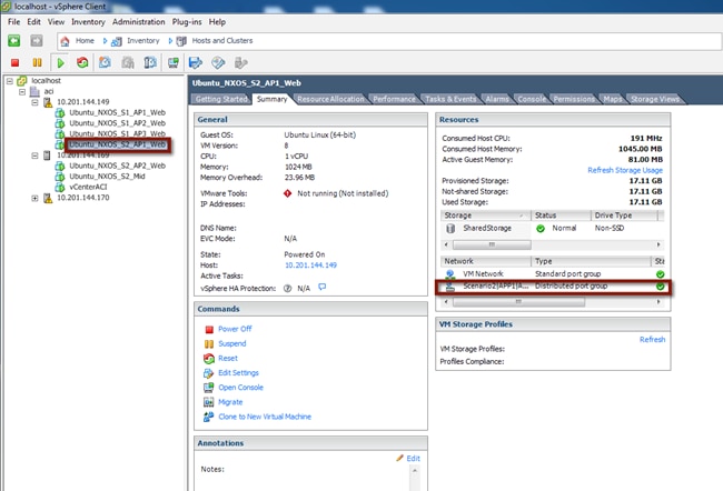
To validate the port group change for the virtual machine and the continued communication with the infrastructure, start a continuous ping from AppOneWeb to its gateway. During the VM port group association change, document any packet loss or abnormality.
In the figure below, note that after the port group change, you can still ping the default gateway (still deployed on the FabricPath spine devices).
Figure 160: Scenario 2 Port Group Migration Validations
cisco@S2-AppOneWeb:~$ ping 210.1.1.1
PING 210.1.1.1 (210.1.1.1) 56(84) bytes of data.
64 bytes from 210.1.1.1: icmp_seq=1 ttl=255 time=0.676 ms
64 bytes from 210.1.1.1: icmp_seq=2 ttl=255 time=0.549 ms
64 bytes from 210.1.1.1: icmp_seq=3 ttl=255 time=0.516 ms
64 bytes from 210.1.1.1: icmp_seq=4 ttl=255 time=0.531 ms
64 bytes from 210.1.1.1: icmp_seq=5 ttl=255 time=0.595 ms
64 bytes from 210.1.1.1: icmp_seq=6 ttl=255 time=0.638 ms
64 bytes from 210.1.1.1: icmp_seq=7 ttl=255 time=0.582 ms
64 bytes from 210.1.1.1: icmp_seq=8 ttl=255 time=0.600 ms
64 bytes from 210.1.1.1: icmp_seq=9 ttl=255 time=0.636 ms
64 bytes from 210.1.1.1: icmp_seq=10 ttl=255 time=0.601 ms
64 bytes from 210.1.1.1: icmp_seq=11 ttl=255 time=0.617 ms
64 bytes from 210.1.1.1: icmp_seq=12 ttl=255 time=0.647 ms
64 bytes from 210.1.1.1: icmp_seq=13 ttl=255 time=0.602 ms
64 bytes from 210.1.1.1: icmp_seq=14 ttl=255 time=0.586 ms
64 bytes from 210.1.1.1: icmp_seq=15 ttl=255 time=0.590 ms
64 bytes from 210.1.1.1: icmp_seq=16 ttl=255 time=0.573 ms
64 bytes from 210.1.1.1: icmp_seq=17 ttl=255 time=0.627 ms
64 bytes from 210.1.1.1: icmp_seq=19 ttl=255 time=1.12 ms
64 bytes from 210.1.1.1: icmp_seq=20 ttl=255 time=1.14 ms
64 bytes from 210.1.1.1: icmp_seq=21 ttl=255 time=1.11 ms
64 bytes from 210.1.1.1: icmp_seq=22 ttl=255 time=1.19 ms
64 bytes from 210.1.1.1: icmp_seq=23 ttl=255 time=1.14 ms
^C
--- 210.1.1.1 ping statistics ---
23 packets transmitted, 22 received, 4% packet loss, time 22005ms
rtt min/avg/max/mdev = 0.516/0.722/1.198/0.232 ms
cisco@S2-AppOneWeb:~$
Figure 161: Scenario 2 Migrate VMNIC from the FabricPath DVS to ACI-Managed DVS

Validation
Now that you have changed the port group for the S2-AppOneWeb VM, you will repeat all of the verification steps.
Figure 162: Scenario 2 Migrate Host to ACI – AppOneWeb
IFCONFIG::
cisco@S2-AppOneWeb:~$ ifconfig eth0
eth0 Link encap:Ethernet HWaddr 00:50:56:9e:2a:60
inet addr:210.1.1.201 Bcast:210.1.1.255 Mask:255.255.255.0
inet6 addr: fe80::250:56ff:fe9e:2a60/64 Scope:Link
UP BROADCAST RUNNING MULTICAST MTU:1500 Metric:1
RX packets:2030 errors:0 dropped:28 overruns:0 frame:0
TX packets:1204 errors:0 dropped:0 overruns:0 carrier:0
collisions:0 txqueuelen:1000
RX bytes:126766 (126.7 KB) TX bytes:68723 (68.7 KB)
cisco@S2-AppOneWeb:~$
Figure 163: Scenario 2 Migrate Host to ACI – AppOneWeb ARP Validation
ARP –A:
cisco@S2-AppOneWeb:~$ arp –a
? (210.1.1.2) at 38:ed:18:a2:f1:42 [ether] on eth0
? (210.1.1.1) at 00:00:0c:07:ac:d2 [ether] on eth0
? (210.1.1.3) at 38:ed:18:a2:f3:c2 [ether] on eth0
cisco@S2-AppOneWeb:~$
In the figure below, note that S2-AppOneWeb can ping its gateway (210.1.1.1) as well as the loopback on DCCORE01 (199.199.199.1).
Figure 164: Scenario 2 Migrate Host to ACI – AppOneWeb Ping Validation
PING::
cisco@S2-AppOneWeb:~$ ping 210.1.1.1 -c 1
PING 210.1.1.1 (210.1.1.1) 56(84) bytes of data.
64 bytes from 210.1.1.1: icmp_seq=1 ttl=255 time=1.70 ms
--- 210.1.1.1 ping statistics ---
1 packets transmitted, 1 received, 0% packet loss, time 0ms
rtt min/avg/max/mdev = 1.700/1.700/1.700/0.000 ms
cisco@S2-AppOneWeb:~$
cisco@S2-AppOneWeb:~$ ping 199.199.199.1 -c 1
PING 199.199.199.1 (199.199.199.1) 56(84) bytes of data.
64 bytes from 199.199.199.1: icmp_seq=1 ttl=254 time=0.775 ms
--- 199.199.199.1 ping statistics ---
1 packets transmitted, 1 received, 0% packet loss, time 0ms
rtt min/avg/max/mdev = 0.775/0.775/0.775/0.000 ms
cisco@S2-AppOneWeb:~$
In the figure below, note that traceroute still shows that you are going through the FabricPath environment to reach the loopback (199.199.199.1) on DCCORE01.
Figure 165: Scenario 2 Migrate Host to ACI – AppOneWeb Traceroute Validation
TRACEROUTE::
cisco@S2-AppOneWeb:~$ traceroute 210.1.1.1
traceroute to 210.1.1.1 (210.1.1.1), 30 hops max, 60 byte packets
1 210.1.1.1 (210.1.1.1) 3.945 ms 4.387 ms 4.473 ms
cisco@S2-AppOneWeb:~$
cisco@S2-AppOneWeb:~$ traceroute 199.199.199.1
traceroute to 199.199.199.1 (199.199.199.1), 30 hops max, 60 byte packets
1 210.1.1.2 (210.1.1.2) 0.754 ms 210.1.1.3 (210.1.1.3) 0.598 ms 210.1.1.2 (210.1.1.2) 0.760 ms
2 199.199.199.1 (199.199.199.1) 1.566 ms 3.465 ms 3.673 ms
cisco@S2-AppOneWeb:~$
Figure 166: Scenario 2 Validation – FabricPath domain
SHOW MAC ADDRESS-TABLE::
FP_Core01# show mac address-table address 00:50:56:9e:2a:60
Note: MAC table entries displayed are getting read from software.
Use the 'hardware-age' keyword to get information related to 'Age'
Legend:
* - primary entry, G - Gateway MAC, (R) - Routed MAC, O - Overlay MAC
age - seconds since last seen,+ - primary entry using vPC Peer-Link,
(T) - True, (F) - False , ~~~ - use 'hardware-age' keyword to retrieve age info
VLAN MAC Address Type age Secure NTFY Ports/SWID.SSID.LID
---------+-----------------+--------+---------+------+----+------------------
* 210 0050.569e.2a60 dynamic ~~~ F F Po11
FP_Core01#
Figure 167: Scenario 2 Validation – FabricPath domain ARP Validation
SHOW IP ARP::
FP_Core01# show ip arp 210.1.1.201 vrf vrf210
Flags: * - Adjacencies learnt on non-active FHRP router
+ - Adjacencies synced via CFSoE
# - Adjacencies Throttled for Glean
D - Static Adjacencies attached to down interface
IP ARP Table
Total number of entries: 1
Address Age MAC Address Interface
210.1.1.201 00:09:32 0050.569e.2a60 Vlan210
FP_Core01#
Figure 168: Scenario 2 Validation – FabricPath domain Routing Table Validation
SHOW IP ROUTE::
FP_Core01# show ip route 210.1.1.0 vrf vrf210
IP Route Table for VRF "vrf210"
'*' denotes best ucast next-hop
'**' denotes best mcast next-hop
'[x/y]' denotes [preference/metric]
'%<string>' in via output denotes VRF <string>
210.1.1.0/24, ubest/mbest: 1/0, attached
*via 210.1.1.2, Vlan210, [0/0], 1d23h, direct
FP_Core01#
Figure 169: Scenario 2 Validation – ACI Fabric Endpoint Table Validation
SHOW ENDPOINT::
Leaf1# show endpoint ip 210.1.1.201
Legend:
O - peer-attached H - vtep a - locally-aged S - static
V - vpc-attached p - peer-aged L - local M - span
s - static-arp B - bounce
+-------------------+---------------+-----------------+--------------+-------------+
VLAN/ Encap MAC Address MAC Info/ Interface
Domain VLAN IP Address IP Info
+-------------------+---------------+-----------------+--------------+-------------+
42 vlan-1007 0050.569e.2a60 LV po13
Scenario2:VRF210 vlan-1007 210.1.1.201 LV
Leaf1#
Figure 170: Scenario 2 Validation – ACI Fabric Routing Table Validation
SHOW IP ROUTE::
Leaf1# show ip route vrf Scenario2:VRF210 210.1.1.0/24
IP Route Table for VRF "Scenario2:VRF210"
'*' denotes best ucast next-hop
'**' denotes best mcast next-hop
'[x/y]' denotes [preference/metric]
'%<string>' in via output denotes VRF <string>
210.1.1.0/24, ubest/mbest: 1/0, attached, direct, pervasive
*via 10.0.40.65%overlay-1, [1/0], 00:08:56, static
recursive next hop: 10.0.40.65/32%overlay-1
Leaf1#
Moving the Default Gateway from FabricPath to the ACI Fabric
Now that all of the VMs have been relocated in their new ACI-managed DVS, the default gateway can be moved from the FabricPath environment into the ACI fabric.
Figure 171: Scenario 2 – Hosts and Clusters
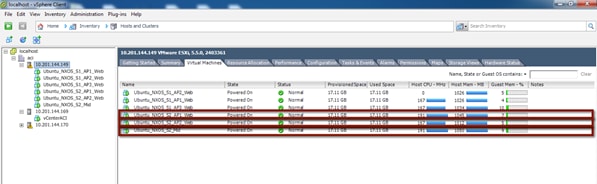
Gateway Migration
Before starting the migration, start a ping from the S2-AppOneWeb VM to the gateway address. After that, migrate the VLAN 210 gateway from the FabricPath domain to the ACI fabric (into BD210).
Figure 172: Scenario 2 Validation – ACI Fabric
cisco@S2-AppOneWeb:~$ ping 210.1.1.1
PING 210.1.1.1 (210.1.1.1) 56(84) bytes of data.
64 bytes from 210.1.1.1: icmp_seq=1 ttl=255 time=0.676 ms
64 bytes from 210.1.1.1: icmp_seq=2 ttl=255 time=0.549 ms
64 bytes from 210.1.1.1: icmp_seq=3 ttl=255 time=0.516 ms
64 bytes from 210.1.1.1: icmp_seq=4 ttl=255 time=0.531 ms
64 bytes from 210.1.1.1: icmp_seq=5 ttl=255 time=0.595 ms
64 bytes from 210.1.1.1: icmp_seq=6 ttl=255 time=0.638 ms
64 bytes from 210.1.1.1: icmp_seq=7 ttl=255 time=0.582 ms
64 bytes from 210.1.1.1: icmp_seq=8 ttl=255 time=0.600 ms
64 bytes from 210.1.1.1: icmp_seq=9 ttl=255 time=0.636 ms
64 bytes from 210.1.1.1: icmp_seq=10 ttl=255 time=0.601 ms
64 bytes from 210.1.1.1: icmp_seq=11 ttl=255 time=0.617 ms
64 bytes from 210.1.1.1: icmp_seq=12 ttl=255 time=0.647 ms
64 bytes from 210.1.1.1: icmp_seq=13 ttl=255 time=0.602 ms
64 bytes from 210.1.1.1: icmp_seq=14 ttl=255 time=0.586 ms
64 bytes from 210.1.1.1: icmp_seq=15 ttl=255 time=0.590 ms
64 bytes from 210.1.1.1: icmp_seq=16 ttl=255 time=0.573 ms
64 bytes from 210.1.1.1: icmp_seq=17 ttl=255 time=0.627 ms
64 bytes from 210.1.1.1: icmp_seq=19 ttl=255 time=1.12 ms
64 bytes from 210.1.1.1: icmp_seq=20 ttl=255 time=1.14 ms
64 bytes from 210.1.1.1: icmp_seq=21 ttl=255 time=1.11 ms
64 bytes from 210.1.1.1: icmp_seq=22 ttl=255 time=1.19 ms
64 bytes from 210.1.1.1: icmp_seq=23 ttl=255 time=1.14 ms
^C
--- 210.1.1.1 ping statistics ---
23 packets transmitted, 22 received, 4% packet loss, time 22005ms
rtt min/avg/max/mdev = 0.516/0.722/1.198/0.232 ms
cisco@S2-AppOneWeb:~$
As seen above, one packet is dropped during the gateway migration.
The following process was used for the gateway migration:
1. Shut down (manually) the SVI interfaces for VLAN 210 on FP_CORE1 and FP_CORE2 at the same time.
2. Add static routes on DCCORE01/02 to the appropriate updated interfaces pointing to the new ASA firewalls connected to the ACI fabric for VLAN 210 (and later for VLANs 211-212).
3. At about the same time, leverage an XML post to configure the default gateway MAC and IP address in the ACI fabric.
Figure 173: XML Post to migrate the HSRP Gateway to the ACI Fabric BD
<fvBD arpFlood="yes" descr="" dn="uni/tn-Scenario2/BD-BD210" epMoveDetectMode="" limitIpLearnToSubnets="yes" llAddr="::" mac="00:00:0c:07:ac:d2" multiDstPktAct="encap-flood" name="BD100" unicastRoute="yes" unkMacUcastAct="flood" unkMcastAct="flood"><fvRsBDToNdP tnNdIfPolName=""/><fvRsCtx tnFvCtxName="VRF210"/><fvRsIgmpsn tnIgmpSnoopPolName=""/><fvSubnet ctrl="" descr="" ip="210.1.1.254/24" name="" preferred="no" scope="public" status="deleted"/><fvSubnet ctrl="" descr="" ip="210.1.1.1/24" name="" preferred="no" scope="public"/><fvRsBdToEpRet resolveAct="resolve" tnFvEpRetPolName=""/></fvBD>
Important parts of the above XML Post:
· Configured BD210
· Changed his MAC address to the SAME MAC address of the gateway on the FP spines (HSRP vMAC). This ensures that hosts will not have to re-ARP for the gateway and speeds up convergence time.
· Removed the 210.1.1.254/24 address – this was initially used to test the L3Out connectivity.
· Added the 210.1.1.1 GW address.
The XML post takes less than a second to reconfigure the BD across the fabric. Below is a screenshot of how to post to the fabric. This can also be achieved with Postman (for Google Chrome) or other XML or JSON programs.
Figure 174: Scenario 2 Example POST
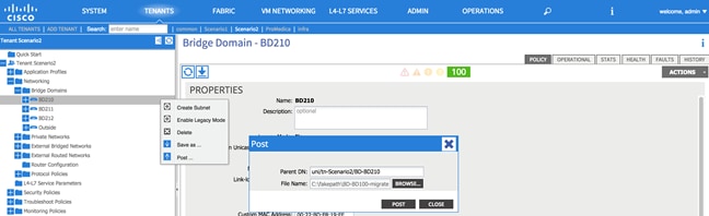
All the VMs are now on the ACI-managed DVS, and their default gateway is now on the ACI fabric.
Figure 175: Scenario 2 Migrate Default Gateway from the FabricPath Domain to ACI Fabric
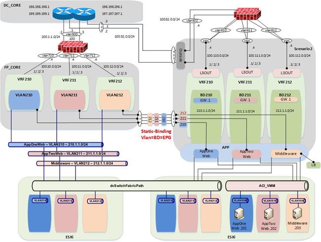
Validation
Figure 176: Scenario 2 Migrate Host to ACI – AppOneWeb
IFCONFIG::
cisco@S2-AppOneWeb:~$ ifconfig eth0
eth0 Link encap:Ethernet HWaddr 00:50:56:9e:2a:60
inet addr:210.1.1.201 Bcast:210.1.1.255 Mask:255.255.255.0
inet6 addr: fe80::250:56ff:fe9e:2a60/64 Scope:Link
UP BROADCAST RUNNING MULTICAST MTU:1500 Metric:1
RX packets:2030 errors:0 dropped:28 overruns:0 frame:0
TX packets:1204 errors:0 dropped:0 overruns:0 carrier:0
collisions:0 txqueuelen:1000
RX bytes:126766 (126.7 KB) TX bytes:68723 (68.7 KB)
cisco@S2-AppOneWeb:~$
In the figure below, note that ARP still shows the same MAC for the default gateway. This is because the MAC address on BD210 on the fabric was changed to match the HSRP vMAC address on the old FabricPath environment.
Figure 177: Scenario 2 Migrate Host to ACI – AppOneWeb ARP Validation
ARP –A:
cisco@S2-AppOneWeb:~$ arp –a
? (210.1.1.2) at 38:ed:18:a2:f1:42 [ether] on eth0
? (210.1.1.1) at 00:00:0c:07:ac:d2 [ether] on eth0
? (210.1.1.3) at 38:ed:18:a2:f3:c2 [ether] on eth0
cisco@S2-AppOneWeb:~$
In the figure below, note that S2-AppOneWeb can ping its gateway (210.1.1.1) as well as the loopback on DCCORE01 (199.199.199.1), just as you could do before. All traffic is now flowing through the ACI fabric, up to the FWs, and then back down into the appropriate VRF (private network).
Figure 178: Scenario 2 Migrate Host to ACI – AppOneWeb Ping Validation
PING::
cisco@S2-AppOneWeb:~$ ping 210.1.1.1 -c 1
PING 210.1.1.1 (210.1.1.1) 56(84) bytes of data.
64 bytes from 210.1.1.1: icmp_seq=1 ttl=63 time=0.182 ms
--- 210.1.1.1 ping statistics ---
1 packets transmitted, 1 received, 0% packet loss, time 0ms
rtt min/avg/max/mdev = 0.182/0.182/0.182/0.000 ms
cisco@S2-AppOneWeb:~$
cisco@S2-AppOneWeb:~$ ping 211.1.1.201 -c 1
PING 211.1.1.201 (211.1.1.201) 56(84) bytes of data.
64 bytes from 211.1.1.201: icmp_seq=1 ttl=60 time=0.465 ms
--- 211.1.1.201 ping statistics ---
1 packets transmitted, 1 received, 0% packet loss, time 0ms
rtt min/avg/max/mdev =
0.465/0.465/0.465/0.000 ms
cisco@S2-AppOneWeb:~$
cisco@S2-AppOneWeb:~$ ping 212.1.1.201 -c 1
PING 212.1.1.201 (212.1.1.201) 56(84) bytes of data.
64 bytes from 212.1.1.201: icmp_seq=1 ttl=60 time=0.477 ms
--- 212.1.1.201 ping statistics ---
1 packets transmitted, 1 received, 0% packet loss, time 0ms
rtt min/avg/max/mdev = 0.477/0.477/0.477/0.000 ms
cisco@S2-AppOneWeb:~$
cisco@S2-AppOneWeb:~$ ping 199.199.199.1 -c 1
PING 199.199.199.1 (199.199.199.1) 56(84) bytes of data.
64 bytes from 199.199.199.1: icmp_seq=1 ttl=253 time=0.787 ms
--- 199.199.199.1 ping statistics ---
1 packets transmitted, 1 received, 0% packet loss, time 0ms
rtt min/avg/max/mdev = 0.787/0.787/0.787/0.000 ms
cisco@S2-AppOneWeb:~$
Figure 179: Scenario 2 Migrate Host to ACI – AppOneWeb Traceroute Validation
TRACEROUTE::
cisco@S2-AppOneWeb:~$ traceroute 210.1.1.1
traceroute to 210.1.1.1 (210.1.1.1), 30 hops max, 60 byte packets
1 210.1.1.1 (210.1.1.1) 3.945 ms 4.387 ms 4.473 ms
cisco@S2-AppOneWeb:~$
cisco@S2-AppOneWeb:~$ traceroute 199.199.199.1
traceroute to 199.199.199.1 (199.199.199.1), 30 hops max, 60 byte packets
1 210.1.1.2 (210.1.1.2) 0.754 ms 210.1.1.3 (210.1.1.3) 0.598 ms 210.1.1.2 (210.1.1.2) 0.760 ms
2 199.199.199.1 (199.199.199.1) 1.566 ms 3.465 ms 3.673 ms
cisco@S2-AppOneWeb:~$
Figure 180: Scenario 2 Validation – FabricPath Domain
SHOW MAC ADDRESS-TABLE::
FP_Core01# show mac address-table address 00:50:56:9e:2a:60
Note: MAC table entries displayed are getting read from software.
Use the 'hardware-age' keyword to get information related to 'Age'
Legend:
* - primary entry, G - Gateway MAC, (R) - Routed MAC, O - Overlay MAC
age - seconds since last seen,+ - primary entry using vPC Peer-Link,
(T) - True, (F) - False , ~~~ - use 'hardware-age' keyword to retrieve age info
VLAN MAC Address Type age Secure NTFY Ports/SWID.SSID.LID
---------+-----------------+--------+---------+------+----+------------------
* 210 0050.569e.2a60 dynamic ~~~ F F Po11
FP_Core01#
In the figure below, note that no ARP entry shows up, as the SVI for VLAN 210 is now shutdown on FP_Core01.
Figure 181: Scenario 2 Validation – FabricPath Domain ARP Validation
SHOW IP ARP::
FP_Core01# show ip arp 210.1.1.201 vrf vrf210
Flags: * - Adjacencies learnt on non-active FHRP router
+ - Adjacencies synced via CFSoE
# - Adjacencies Throttled for Glean
D - Static Adjacencies attached to down interface
IP ARP Table
Total number of entries: 1
Address Age MAC Address Interface
FP_Core01#
In the figure below, note that route to 210.1.0.0/24 no longer shows up as directly connected; routing will follow the static 0.0.0.0/0 to the FW next-hop (100.10.0.4).
Figure 182: Scenario 2 Validation – FabricPath Domain Routing Table Validation
SHOW IP ROUTE::
FP_Core01# show ip route 210.1.1.0 vrf vrf210
IP Route Table for VRF "vrf210"
'*' denotes best ucast next-hop
'**' denotes best mcast next-hop
'[x/y]' denotes [preference/metric]
'%<string>' in via output denotes VRF <string>
0.0.0.0/0, ubest/mbest: 1/0
*via 100.10.0.4, [1/0], 08:52:47, static
FP_Core01#
Figure 183: Scenario 2 Validation – ACI Fabric Endpoint Table Validation
SHOW ENDPOINT::
Leaf1# show endpoint ip 210.1.1.201
Legend:
O - peer-attached H - vtep a - locally-aged S - static
V - vpc-attached p - peer-aged L - local M - span
s - static-arp B - bounce
+-------------------+---------------+-----------------+--------------+-------------+
VLAN/ Encap MAC Address MAC Info/ Interface
Domain VLAN IP Address IP Info
+-------------------+---------------+-----------------+--------------+-------------+
42 vlan-1007 0050.569e.2a60 LV po13
Scenario2:VRF210 vlan-1007 210.1.1.201 LV
Leaf1#
Figure 184: Scenario 2 Validation – ACI Fabric Routing Table Validation
SHOW IP ROUTE::
Leaf1# show ip route vrf Scenario2:VRF210 210.1.1.0/24
IP Route Table for VRF "Scenario2:VRF210"
'*' denotes best ucast next-hop
'**' denotes best mcast next-hop
'[x/y]' denotes [preference/metric]
'%<string>' in via output denotes VRF <string>
210.1.1.0/24, ubest/mbest: 1/0, attached, direct, pervasive
*via 10.0.40.65%overlay-1, [1/0], 00:08:56, static
recursive next hop: 10.0.40.65/32%overlay-1
Leaf1#
Fabric Optimization
The final step (once all servers have been migrated from the FabricPath environment to the ACI fabric) is to enable optimized Layer 2 forwarding on all bridge domains.
· Optimized forwarding of unknown Layer 2 unicast packets reduces the needless flooding of unknown unicast packets on the bridge domain. If a packet is not known to the fabric, it is discarded.
· Disabling ARP flooding reduces the amount of broadcast packets on the bridge domain. ARP requests are routed by the fabric to known destinations as opposed to flooding.
· Changing the multi-destination flooding to “Flood in Encapsulation” ensures that all broadcast level packets are flooded inside of an EPG, and not at the bridge domain level.
Table 51: Scenario 2 Forwarding Semantics
| Forwarding Semantic |
Configuration |
| Layer 2 Unknown Unicast |
Hardware Proxy |
| Layer 2 Unknown Multicast Flooding |
Flood |
| Multi Destination Flooding |
Flood in Encapsulation |
| Unicast Routing |
Enabled |
| Enforce subnet check for IP learning |
Enabled |
| ARP Flooding |
Disabled |
Once all servers have been moved into ACI fabric and Layer 2 extensions to the FabricPath environment are no longer needed, it is possible to disconnect the cables and deconfigure the Layer 2 vPC logical connection. The figure below highlights the connectivity that remains in place after the migration is completed.
Figure 185: Scenario 2 End State after Migration is Complete
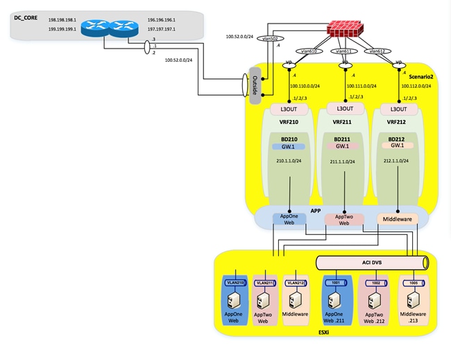
Lessons Learned
In the lessons learned section, you are guided through some of the issues experienced during time spent migrating the workloads from the FabricPath environment to the ACI fabric.
UCS B-series and ACI integration considerations
VM integration with ACI notables
Reboot of ESXi host needed after enabling CDP from UCS Manager
After enabling CDP in UCS manager, CDP did not show up as configured on the VMNIC interfaces in vCenter until after the associated ESXi hosts were rebooted.
Note: It is necessary to enable CDP from the UCS FIs towards the ESX hosts for VM networking integration with ACI. VM integration with UCS-B Series and ACI requires specific configurations. Refer to the following document:
http://www.cisco.com/c/en/us/support/docs/cloud-systems-management/application-policy-infrastructure-controller-apic/118965-config-vmm-aci-ucs-00.html.
Infra Address Pool
Infra Address Pool Considerations
When configuring the infra address pool while bringing up the fabric, you are asked to provide a pool of IP addresses, which are used to allocate addresses for VTEPs for leaf switches, spines, and APICs. While this address pool is constrained to its own VRF, there are routing implications on the APICs.
Figure 186: APIC routing table – Netstat -r
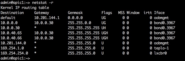
For example, for the APIC above, you used the default 10.0.0.0/16 address pool for a VTEP infra address pool. However, a problem can arise if you need to reach a vCenter for VM networking integration with an address of 10.255.1.1. Because the APIC has a route going to 10.0.0.0/16 already, the traffic to the vCenter will be blackholed.
The workarounds are very useful; you can insert static routes via Linux commands, but these do not survive a reload. Additionally, the only way to redo the infra address pool is to wipe the fabric and reconfigure.
Note: It is important to correctly address the infra address pool the first time.
· Use unique addressing for your infra addressing pool
· A /23 is the minimum addressing option
ACI Object Naming Conventions
Anytime you are configuring something on ACI, whether it is an EPG, a private network, an interface policy group, or a switch selector, you are configuring a managed object. In ACI once you configure a managed object, it cannot be renamed. You must delete and recreate it if you want to modify its name. You can’t rename and object because once it’s been created, an object automatically has child objects that filter up to it. (This is comparable to a root file structure.) You cannot change the “root” object without affecting all of the downstream objects. Before you start configuring anything, come up with a naming convention for your enterprise for ACI. The following is just a starting point for objects to name.
Application Profile
Application Profiles were originally developed to house groups of end point groups that make up a common application. However, if you are deploying your fabric in network-centric mode (i.e., VLAN=EPG=BD), does this application profile really matter?
If you are deploying your ACI fabric in application-centric mode, or even in hybrid mode (i.e., some ACI-centric Apps, and some network centric), I would make the argument that application profiles for ACI-centric mode are fairly straight forward. Below is an example of an application-centric application profile.
Application Profile MS_Exchange_Corp
· EPG Exchange_Middleware
· EPG DB_for_Exchange
· EPG OWA
· EPG Exchange_MISC
However, when you start to deploy application profiles for network-centric mode, this is when more questions start to creep in.
1. Make up a list of all VLANs and EPGs that will make up your fabric (that you know about).
2. Will some application profiles be ACI-centric?
3. For the EPGs, which will not fall under an ACI-centric application profile, how should you group the remaining EPGs?
a. One large “Legacy” application profile?
b. Should you group the Network-Centric EPGs by function?
i. Network Management VLAN – Application Profile Network_Mgmt
ii. Management_Vlan_For_Compute
Example of a hybrid ACI fabric:
Figure 187: Hybrid ACI Fabric Example
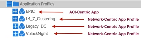
· The EPIC application profile holds EPGs that relate to an application called “EPIC”.
· The L4_7_Clustering application profile holds all VLANs/EPGs which support Layer 4 to Layer 7 clustered for ASAs and load balancers.
· The Legacy_DC application profile is the “catch-all” application profile for the remaining network-centric VLANs, which will be migrated into the ACI fabric, but do not have a specific purpose.
· VblockMgmt is an application profile, which contains management VLANs and port groups for the UCS servers in the Vblock (i.e., vmkernel, management).
Interface Policy Groups
Interface policy groups allow users to apply configurations across a potentially large number of switches. An administrator defines switch profiles that associate interface configurations in a single policy group. In this way, large numbers of interfaces across the fabric can be configured at once.
However, in addition to the ability to define policy groups for a large group of switches and switch interfaces (i.e., a common policy group for 1GigAuto access ports with CDP enabled), policy groups are used for things that are not commonly reused, like port-channels and vPC interfaces. When you use policy groups for port channels and vPCs, the name of the policy group becomes very important.
Figure 188: Interface Policy Groups
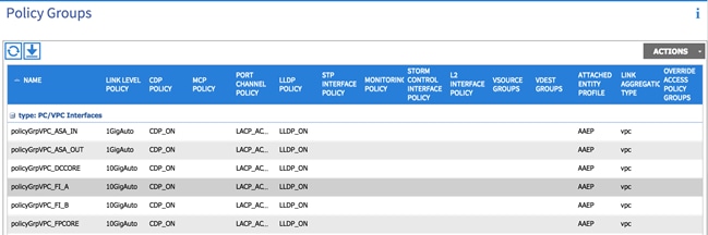
The naming convention of the interface policy groups is extremely important, as this is the name that will show up in several places in the ACI fabric during configurations. A sampling of places where your interface policy group will show up:
Figure 189: Tenant EPG statis bindings (for vPCs and port channels)

Figure 190: Tenant L3Out interface selection (for vPCs and port channels)
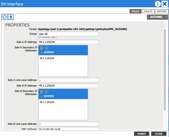
As you can see from the previous example, when you select which interface to deploy, the L3Out across (which is a vPC in this case), you do not select the switch and switch interface, instead, you select the switches and associated vPC policy group. Make sure the name you choose passes the 2am test; meaning, someone working in the NOC will know what you are talking about at 2am during an outage.
Our naming convention for the fabric:
· 1 2 3
· policyGrpVPC_DCCORE
· #1 – It is a policy group
· #2 – It is a vPC (could be a vPC, PC, or access)
· #3 – What is the device you are connecting to? In this case, there is a double-sided vPC to DCCORE01/02, so it gets shortened to DCCORE.
These naming conventions are suggestions. It is important that you develop naming conventions before you start configuring policy groups.
Obtaining Documentation and Submitting a Service Request
For information on obtaining documentation, using the Cisco Bug Search Tool (BST), submitting a service request, and gathering additional information, see What’s New in Cisco Product Documentation at: http://www.cisco.com/c/en/us/td/docs/general/whatsnew/whatsnew.html.
Subscribe to What’s New in Cisco Product Documentation, which lists all new and revised Cisco technical documentation, as an RSS feed and deliver content directly to your desktop using a reader application. The RSS feeds are a free service.
Legal Information
THE SPECIFICATIONS AND INFORMATION REGARDING THE PRODUCTS IN THIS MANUAL ARE SUBJECT TO CHANGE WITHOUT NOTICE. ALL STATEMENTS, INFORMATION, AND RECOMMENDATIONS IN THIS MANUAL ARE BELIEVED TO BE ACCURATE BUT ARE PRESENTED WITHOUT WARRANTY OF ANY KIND, EXPRESSED OR IMPLIED. USERS MUST TAKE FULL RESPONSIBILITY FOR THEIR APPLICATION OF ANY PRODUCTS.
THE SOFTWARE LICENSE AND LIMITED WARRANTY FOR THE ACCOMPANYING PRODUCT ARE SET FORTH IN THE INFORMATION PACKET THAT SHIPPED WITH THE PRODUCT AND ARE INCORPORATED HEREIN BY THIS REFERENCE. IF YOU ARE UNABLE TO LOCATE THE SOFTWARE LICENSE OR LIMITED WARRANTY, CONTACT YOUR CISCO REPRESENTATIVE FOR A COPY.
The Cisco implementation of TCP header compression is an adaptation of a program developed by the University of California, Berkeley (UCB) as part of UCB’s public domain version of the UNIX operating system. All rights reserved. Copyright © 1981, Regents of the University of California.
NOTWITHSTANDING ANY OTHER WARRANTY HEREIN, ALL DOCUMENT FILES AND SOFTWARE OF THESE SUPPLIERS ARE PROVIDED “AS IS” WITH ALL FAULTS. CISCO AND THE ABOVE-NAMED SUPPLIERS DISCLAIM ALL WARRANTIES, EXPRESSED OR IMPLIED, INCLUDING, WITHOUT LIMITATION, THOSE OF MERCHANTABILITY, FITNESS FOR A PARTICULAR PURPOSE AND NONINFRINGEMENT OR ARISING FROM A COURSE OF DEALING, USAGE, OR TRADE PRACTICE.
IN NO EVENT SHALL CISCO OR ITS SUPPLIERS BE LIABLE FOR ANY INDIRECT, SPECIAL, CONSEQUENTIAL, OR INCIDENTAL DAMAGES, INCLUDING, WITHOUT LIMITATION, LOST PROFITS OR LOSS OR DAMAGE TO DATA ARISING OUT OF THE USE OR INABILITY TO USE THIS MANUAL, EVEN IF CISCO OR ITS SUPPLIERS HAVE BEEN ADVISED OF THE POSSIBILITY OF SUCH DAMAGES.
Any Internet Protocol (IP) addresses and phone numbers used in this document are not intended to be actual addresses and phone numbers. Any examples, command display output, network topology diagrams, and other figures included in the document are shown for illustrative purposes only. Any use of actual IP addresses or phone numbers in illustrative content is unintentional and coincidental.
All printed copies and duplicate soft copies are considered uncontrolled copies and the original online version should be referred to for latest version.
Cisco has more than 200 offices worldwide. Addresses, phone numbers, and fax numbers are listed on the Cisco website at www.cisco.com/go/offices.
Cisco and the Cisco logo are trademarks or registered trademarks of Cisco and/or its affiliates in the U.S. and other countries. To view a list of Cisco trademarks, go to this URL: www.cisco.com/go/trademarks. Third-party trademarks mentioned are the property of their respective owners. The use of the word partner does not imply a partnership relationship between Cisco and any other company. (1110R)
© 2014-2017 Cisco Systems, Inc. All rights reserved.
 Feedback
Contact Cisco
- Open a Support Case

- (Requires a Cisco Service Contract)