New and Changed Information
The following table provides an overview of the significant changes up to the current release. The table does not provide an exhaustive list of all changes or of the new features up to this release.
|
Cisco APIC Release Version |
Feature |
Description |
|---|---|---|
|
Release 3.1(x) |
N9K-C9364C switch support for Multi-Site |
Cisco ACI Multi-Site is now supported on the Cisco Nexus Series N9K-C9364C switch |
|
Release 3.0(1k) |
Cisco APIC in a Cisco ACI Multi-Site Topology |
Cisco ACI Multi-Site, complementary product to APIC is introduced. |
About Cisco ACI Multi-Site
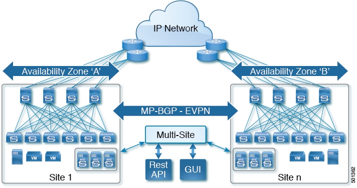
As the newest advance on the Cisco ACI methods to interconnect networks, Cisco ACI Multi-Site is an architectural approach for interconnecting and managing multiple sites, each serving as a single fabric and availability zone. As shown in the diagram, the Multi-Site architecture has three main functional components:
-
Two or more ACI fabrics built with Nexus 9000 switches deployed as leaf and spine nodes.
-
One APIC cluster domain in each fabric.
-
An inter-site policy manager, named Cisco ACI Multi-Site, which is used to manage the different fabrics and to define inter-site policies.
Multi-Site has the following benefits:
-
Complementary with Cisco APIC, in Multi-Site each site is an availability zone (APIC cluster domain), which can be configured to be a shared or isolated change-control zone.
-
MP-BGP EVPN is used as the control plane between sites, with data-plane VXLAN encapsulation across sites.
-
The Multi-Site solution enables extending the policy domain end-to-end across fabrics. You can create policies in the Multi-Site GUI and push them to all sites or selected sites. Alternatively, you can import tenants and their policies from a single site and deploy them on other sites.
-
Multi-Site enables a global view of site health.
-
From the GUI of the Multi-Site Policy Manager, you can launch site APICs.
-
Cross-site namespace normalization is performed by the connecting spine switches. This function requires Cisco Nexus 9000 Series switches with "EX" on the end of the name, or newer.
-
Disaster recovery scenarios offering IP mobility across sites is one of the typical Multi-Site use cases.
For information about hardware requirements and compatibility, see Cisco ACI Multi-Site Hardware Requirements Guide.
For best practices for Multi-Site, see the Deployment Best Practices in Cisco ACI Multi-Site Architecture White Paper.
For the Cisco ACI Multi-Site documentation set, see http://www.cisco.com/c/en/us/support/cloud-systems-management/application-policy-infrastructure-controller-apic/tsd-products-support-series-home.html.
Limitations and Caveats
For limitations and Caveats, see the Cisco ACI Multi-Site Release Notes.
Prerequisites for Using Multi-Site with APIC
Before you can manage an APIC cluster/fabric with Multi-Site, you must perform the following tasks in the APIC GUI:
-
Before connecting a Cisco APIC cluster (fabric) in a Cisco ACI Multi-Site topology, you must configure the Overlay Tunnel Endpoint (TEP) in the Fabric Ext Connection Policy for each fabric; for more information, see Defining the Overlay TEP Using the APIC GUI.
Defining the Overlay TEP for Cisco APIC Sites Using the Cisco APIC GUI
Before connecting a Cisco APIC cluster (fabric) in a Cisco ACI Multi-Site topology, you must configure the Overlay Tunnel Endpoint (TEP) in the Fabric Ext Connection Policy for each fabric.
The Create Intrasite/Intersite Profile panel in the Cisco APIC GUI is used to add connection details for Cisco APIC multipod, remote leaf switches connecting to the Cisco ACI fabric, and APIC sites managed by Cisco ACI Multi-Site Orchestrator. When the Cisco ACI Multi-Site infrastructure has been configured, the Cisco ACI Multi-Site Orchestrator adds the Intersite Overlay TEP to this Cisco APIC policy.
To configure the Overlay TEP in the Fabric Ext Connection Policy for each Cisco APIC site to be managed by Cisco ACI Multi-Site Orchestrator, perform the following steps:
Procedure
| Step 1 |
On the menu bar, click . |
| Step 2 |
On the navigation pane (prior to Cisco APIC, Release 3.1), expand Networking and Protocol Policies. |
| Step 3 |
On the navigation pane (in APIC, Release 3.1 and later), expand Policies and Protocol. |
| Step 4 |
Right-click Fabric Ext Connection Policies and choose Create Intrasite/Intersite Profile. |
| Step 5 |
Click the + symbol on Pod Connection Profile. |
| Step 6 |
Choose the Pod ID from the list. |
| Step 7 |
Enter the IP address for overlay traffic to this pod. |
| Step 8 |
Click Update and Submit. |
Use Cases for APIC with Multi-Site
For the use cases, see the Cisco ACI Multi-Site Fundamentals Guide.
Stretched Bridge Domain with Layer 2 Broadcast Extension
This is the most basic Cisco ACI Multi-Site use case, in which a tenant and VRF are stretched between sites. The EPGs in the VRF (with their bridge domains (BDs) and subnets), as well as their provider and consumer contracts are also stretched between sites.
In this use case, Layer 2 broadcast flooding is enabled across fabrics. Layer 2 broadcast, multicast, and unknown unicast traffic is forwarded across sites leveraging the Head-End Replication (HER) capabilities of the spine nodes that replicate and send the frames to each remote fabric where the Layer 2 BD has been stretched.
Stretched Bridge Domain without Layer 2 Broadcast Extension
This Cisco ACI Multi-Site use case is similar to the first use case where a tenant, VRF, and their EPGs (with their bridge domains and subnets) are stretched between sites. However, in this use case, Layer 2 broadcast flooding is localized at each site. Layer 2 broadcast, multicast and unknown unicast traffic are not forwarded across fabrics over replicated VXLAN tunnels.
Stretched EPG Across Sites
This Cisco ACI Multi-Site use case provides endpoint groups (EPGs) stretched across multiple sites. Stretched EPG is defined as an endpoint group that expands across multiple sites where the underlying networking, site local, and bridge domain can be distinct.
Stretched VRF with Inter-Site Contracts
This Cisco ACI Multi-Site use case provides inter-site communication between endpoints connected to different BDs that are part of the same stretched VRF. VRF Stretching is a convenient way to manage EPGs across sites (and the contracts between them).
The tenant and VRF are stretched across sites, but EPGs and their policies (including subnets) are locally defined. Because the VRF is stretched between sites, contracts govern cross-site communication between the EPGs. Contracts can be conveniently provided (and consumed) within a site or across sites.
Shared Services with Stretched Provider EPG
In this use case, the Provider EPGs in one group of sites offer shared services and the EPGs in another group of sites consume the services. All sites have local EPGs and bridge domains. In the this use case, at the VRF boundary routes are leaked between VRFs for routing connectivity, by importing contracts to the remote sites.
Cisco ACI Multi-Site Cross Launch into Cisco APIC
Cisco ACI Multi-Site currently provides support for basic parameters that a user will choose when creating a Tenant and setting up a site. Most of the Tenant policies are supported by Multi-Site, but in addition to that, users may want to configure some advanced parameters.
The Multi-Site GUI is used to manage the basic properties that a user wants to configure. If there are additional advanced properties that a user wants to configure, the capability to cross launch into Cisco APIC GUI directly from the Multi-Site GUI is provided. If desired by the user, this enables them to configure additional properties directly in APIC.
There are three access points in the Multi-Site GUI where you can cross launch into APIC. From these access points in Multi-Site, you can open a new browser tab with access into APIC. You log in to the APIC at that point for the first time, and the associated screen is displayed in the APIC GUI. After completing tasks in APIC, you can dismiss the browser tab and return to Multi-Site.
Viewing Multi-Site-Managed Objects in the APIC GUI
Viewing Cisco ACI Multi-Site-Managed Objects Using the Cisco APIC GUI
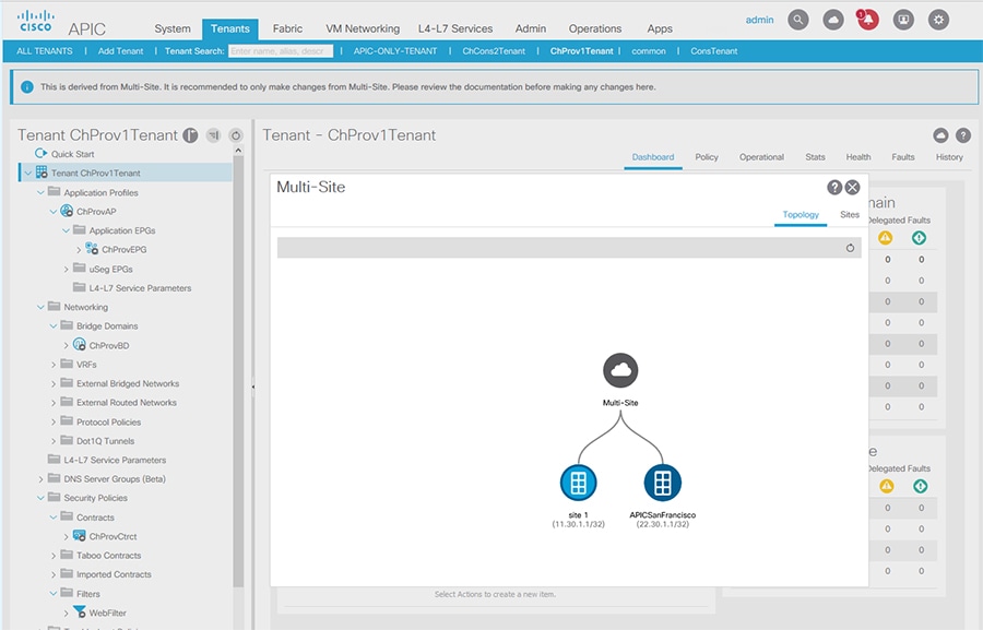
When an APIC cluster is managed by Multi-Site, cloud icons indicate the relationships with other sites.
Before you begin
The APIC cluster/site must be set up to be managed by Cisco ACI Multi-Site.
Procedure
| Step 1 |
To view the relationship of the APIC site with other sites, click the cloud icon at the upper right, next to the settings icons. In the diagram, hover over the light blue site icon to see the local site details, and hover over the dark blue icon to see the remote site details. In the image, T1 and its Application Profile, EPG, BD, VRF, and contracts are marked with cloud icons. This indicates that they are managed by Multi-Site. We recommend that you only make changes to these objects in the Multi-Site GUI. |
||
| Step 2 |
To view the localized or stretched usage of a VRF, bridge domain, or other objects, where there is a Show Usage button on the information page, perform the following steps; for example for Bridge Domain and VRF:
|
||
| Step 3 |
Click Show Usage. Here you can view the nodes or policies using the object.
|
||
| Step 4 |
To set the scope of deployment notification settings for this BD or VRF, click Change Deployment Settings. You can enable warnings to be sent for all deletions and modifications of the object on the Policy tab. |
||
| Step 5 |
To enable or disable Global warnings, check or uncheck the (Global) Show Deployment Warning on Delete/Modify check box. |
||
| Step 6 |
To enable or disable Local warnings, choose Yes or No on the (Local) Show Deployment Warning on Delete/Modify field. |
||
| Step 7 |
To view any past warnings, click the History tab Events or Audit Logs. |
Best Practices for Using APIC in a Multi-Site Topology
Follow these guidelines when using APIC clusters in a Multi-Site Topology.
 Note |
For more best practices for Cisco ACI Multi-Site, see the Deployment Best Practices in Cisco ACI Multi-Site Architecture White Paper. |
-
APIC local site GIPo addresses for bridge domain multicast—These IP addresses, configured during initial APIC setup, can be the same for multiple sites.
-
Modifying Multi-Site-managed objects—Whenever APIC objects are managed by Multi-Site, they should only be modified in the Multi-Site GUI.
-
Multi-Site and APIC user names—To improve legibility of accounting logs, Cisco recommends that Multi-Site users have different names than APIC users that are used for modifying configurations.
-
Multi-Site Infra OSPF details—Cisco recommends that you use OSPF Area 0. If you use an Area ID other than 0, configured it as a "regular" OSPF area type (not a "stub" area type).
-
Shared Services use case, order of deploying—When deploying a provider site group and a consumer site group for shared services by importing tenant policies, deploy the provider tenant policies before deploying the consumer tenant policies. This enables the relation of the consumer tenant to the provider tenant to be properly formed.
-
Caution for Shared Services Use Case—When you import the policies for a consumer tenant and deploy them to multiple sites, including the site where they originated, a new contract is deployed with the same name (different because it is modified by the inter-site relation). To avoid confusion, delete the original contract with the same name on the local site. In the APIC GUI, the original contract can be distinguished from the contract that is managed by Multi-Site, because it is not marked with a cloud icon.
-
Caution when removing a spine switch port from the Multi-Site infrastructure configuration—When removing a spine switch port from the Multi-Site infrastructure, perform the following steps:
-
Click Sites.
-
Click Configure Infra.
-
Click the site where the spine switch is located.
-
Click the spine switch.
-
Click the x on the port details.
-
Click Apply.
-
-
Caution when associating a contract to an external EPG, as provider—Ensure you choose contracts only from the tenant associated with the external EPG. Do not choose contracts from other tenants. If you are associating a contract to the external EPG, as consumer, you can choose any available contract.
 Feedback