New and Changed
The following table provides an overview of the significant changes up to the current release. The table does not provide an exhaustive list of all changes or of the new features up to this release.
|
Cisco APIC Release Version |
Feature |
Description |
|---|---|---|
|
Release 4.1(1) |
Cisco Mini ACI Fabric and Multi-Site. |
Cisco Mini ACI and vAPICs are now supported with Cisco ACI Multi-Site. |
|
Release 4.0(1) |
Cisco Mini ACI Fabric and Virtual APICs. |
This guide was created for the Cisco Mini ACI and Virtual APICs feature. |
Cisco Mini ACI Fabric Overview
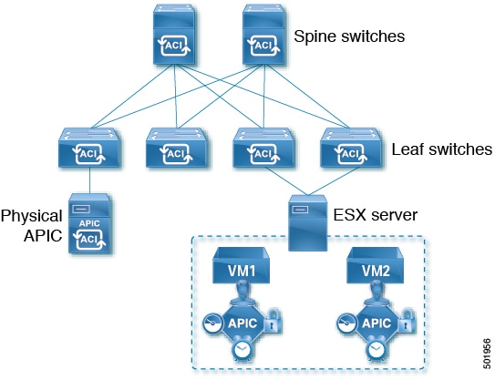
Cisco Application Centric Infrastructure (Cisco ACI) release 4.0(1) introduces the Cisco Mini ACI Fabric for small scale deployment. Mini ACI fabric works with a Cisco Application Policy Infrastructure Controller (APIC) cluster consisting of one physical APIC and two virtual APICs (vAPIC) running in virtual machines. This reduces the physical footprint and cost of the Cisco APIC cluster, allowing ACI fabric to be deployed in scenarios with limited rack space or initial budget, such as a colocation facility or a single-room data center, where a full-scale ACI installations may not be practical due to physical footprint or initial cost.
The following diagram shows an example of a mini Cisco ACI fabric with a physical APIC and two virtual APICs (vAPICs):
Cisco Mini ACI Guidelines and Limitations
Mini ACI Fabric
-
Cisco Mini ACI fabric is supported as a typical on-premises site with Cisco ACI Multi-Site.
-
The following features are not supported:
-
Cisco ACI Multi-Pod
-
Cisco ACI Virtual Pod
-
Remote leaf switch
-
-
Installing and running apps in the Cisco Application Policy Infrastructure Controller (APIC) is not supported.
-
The physical APIC and the ESXi server hosting the virtual APICs must be time synced with the same NTP server. This ensures that there are no sync issues during the upgrades or restarts of the virtual APICs and the cluster converges gracefully.
-
You cannot connect ESXi hosts hosting Cisco Mini ACI virtual APICs using an intermediate switch, including UCS fabric interconnects from Cisco APIC release 6.0(2). ESXi hosts must be directly connected to the Cisco ACI leaf switches.
-
Cisco Mini ACI does not support a policy-based upgrade from releases prior to Cisco APIC release 6.0(2).
-
In the 6.0(2) release and later, from the BootX GUI, you must deploy only one physical APIC. After the Cisco APIC is fully fit, add all the switches and then deploy the virtual APIC using the GUI, followed by configuring the BootX deployment of the virtual APICs.
Physical APIC
While two of the three Cisco APICs in a cluster can now be virtual APICs as virtual machines running in ESXi hosts, you must still install and configure a physical APIC first. The physical APIC is required to discover the spine and leaf switches in the fabric, discover and configure the virtual APICs during their installation, and facilitate the Cisco APIC cluster upgrades.
Although virtual APICs are fully capable of managing your Cisco ACI environment, the physical APIC is responsible for fabric discovery. As such, should the physical APIC become unavailable, you cannot make any physical fabric changes, such as adding or removing a switch, until the physical APIC is recovered.
Virtual APIC
-
During the first boot of a virtual APIC, it will discover and connect to the physical APIC through the Cisco ACI infra VLAN as part of the bootstrap process. Virtual APIC will use a
pass-phrasegenerated by the physical APIC to get its certificate signed by the physical APIC. After the certificates are generated, physical and virtual APICs will exchange discovery messages and the cluster will form. The virtual APIC will become fully-fit after data layer synchronization with the physical APIC is done. -
If you use in-band management with a virtual APIC, the node management IP address subnet and the application EPG IP address subnet cannot be the same.
Scalability Limits
For the Cisco Mini ACI fabric and virtual APIC scalability limits, see the Verified Scalability Guide for your Cisco APIC release at the following location:
Installing and Configuring the Physical Cisco APIC
This procedure installs and configures the physical Cisco APIC server.
Procedure
|
Step 1 |
Follow the instructions in Installing or Recovering Cisco APIC Images to install the physical Cisco APIC server. Install and configure the physical APIC server exactly as you normally would. However, for the small footprint Cisco ACI use case, you must configure the physical APIC server as the first Cisco APIC in your cluster. |
|
Step 2 |
After you have configured the physical APIC server, you create the virtual machines and install the virtual APIC to complete the cluster, as described in Installing and Configuring Virtual APIC. |
Installing and Configuring Virtual APIC
Installing and configuring virtual APICs (vAPIC) in your cluster consists of four steps:
-
Configuring ACI leaf switch ports for infra VLAN trunking, as described in Virtual APIC Installation Prerequisites.
-
Configuring VMware standard vSwitch or DVS and ESXi host, as described in Virtual APIC Installation Prerequisites.
-
Obtaining the pass-phrase generated by the physical APIC, as described in Obtaining Passphrase from Physical APIC
-
Installing and configuring each virtual APIC server, as described in Deploying Virtual APIC Using an OVA.
Cisco provides an OVA image for easy deployment of vAPIC virtual machines using VMware vCenter. However, you can also choose to install the vAPIC directly in the ESXi host using the same ISO file as the physical APIC.
Virtual APIC Installation Prerequisites
Cisco ACI Fabric and Physical APIC Deployment
The ACI fabric must be deployed and running with a physical APIC before any virtual APIC configuration. The physical APIC is responsible for fabric discovery, as well as discovery and registration of the virtual APICs.
Because vAPIC discovery and synchronization depends on a limited duration pass-phrase from the physical APIC, it is recommended that you configure the physical APIC with an NTP server prior to vAPIC installation to avoid any potential time mismatch and certificate synchronization issues between the physical and virtual APICs. Configuring NTP in APIC is described in Provisioning Core ACI Fabric Services chapter of the Cisco APIC Basic Configuration Guide, Release 4.x. Ensure that you obtain the current passphrase from the physical APIC for the vAPIC deployment.
Leaf Switch Ports and Infra VLAN Trunking
The physical and virtual APICs discover and communicate with each other through the Cisco ACI infra VLAN. The leaf switches must have infra VLAN enabled on the ports connected to the ESXi hosts of the vAPIC virtual machines. This is achieved by enabling infra VLAN in the Attachable Access Entity Profile (AEP) of the leaf ports.
You can make these changes from the physical APIC GUI as described in Configuring Leaf Switch Ports for vAPIC Using the Cisco APIC GUI.
ESXi Host and Virtual Machines
The following are the ESXi host, vCenter, and virtual machine requirements for vAPIC.-
The ESXi host must be running VMware ESXi version 7.0 or later
-
The vCenter must be running version 7.0 or later if the ESXi hosts and virtual machines are managed by a vCenter.
-
vAPIC must to be able to communicate with the physical APIC via the Infra VLAN, as such one of the following must be true:
-
The ESXi host is connected directly to a Cisco ACI leaf switch or a vPC pair of leaf switches.
-
-
The ESXi host must have correct UTC time configured.
vAPIC uses the host's time when it first starts and connects to the physical APIC. Any significant time mismatch will cause certificate synchronization issues.
-
The ESXi host must have sufficient resources to host vAPIC virtual machines. Each vAPIC VM requires the following:
-
Memory: 96 GB
-
CPU: 16
-
HDD 1: 3001 GB
A standard HDD can be used for the virtual APIC image installation.
-
HDD 2: 1001 GB SSD
A second, high-performance storage device is required for the virtual APIC datastore.
-
NIC 1 (VMXNET 3): Out of Band
-
NIC 2 (VMXNET 3): ACI Infra VLAN trunking
-
-
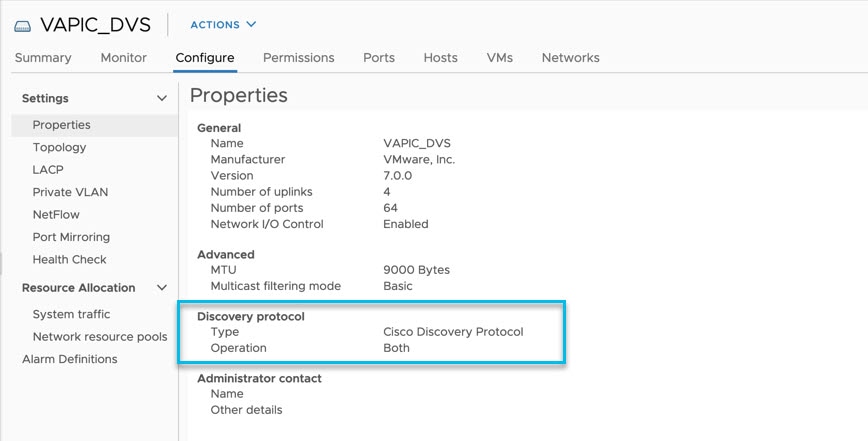
In the VMware vCenter GUI, in the Distributed Switch settings, select the Disabled option for the Discovery Protocol. This enables the leaf switches to directly receive the LLDP packets from APIC. LLDP is used for zero touch fabric discovery.
-
In the VMware vCenter GUI, in the Distributed Port Group settings, allow VLAN-0 with infra VLAN. This enables the DVS to forward the LLDP packets.
1: When you deploy vAPIC, the ESXi host must have a combined storage of at least 600 GB (including swap space). After the initial deployment, the listed storage sizes are sufficient.
 Note |
The current release does not support vMotion for the vAPIC virtual machines. |
Virtual Switch Configuration
Virtual APIC supports VMware DVS and the standard vSwitch. In addition to configuring the leaf switch ports and ESXi host, you must also configure the following for virtual switch and ESXi host:
-
Create a new virtual switch or use an existing one. The virtual switch can be either a standard vSwitch or a DVS
In case of VMM domain integration, a DVS has been created on the vCenter by APIC. vAPIC can use this DVS
-
Configure the virtual switch uplinks for VLAN trunking for the ACI infra VLAN in addition to any other data VLANs
-
Add the ESXi host vmNICs that are connected to ACI leaf switches to the uplink
-
Create a port-group and configure it to VLAN trunking for the ACI infra VLAN
-
In the Distributed Switch, the “Edit Settings” user needs to disable the “Discovery Protocol” so that the connected LEAF can directly receive the LLDP packets from APIC.
In case of VMM domain integration, the above port-group can be created through VMM integration. In the APIC GUI, navigate
to and check the Configure Infra Port Groups box. This will automatically create a port-group named Infra on the VMM Domain DVS in vCenter. However, this port-group is created with a VLAN type and you must manually change it to VLAN Trunking in the port-group's settings using the vSphere client.
In case of a vCenter without VMM integration with ACI, in the left-hand panel of the vCenter UI, navigate to . Then in the right-hand panel, under , click New Distributed Port Group. Finally, in the pop-up window, follow the steps to create the port group specifying VLAN trunking for the VLAN type and the Infra VLAN ID for the VLAN trunk range.
If you are planning to install vAPIC directly in ESXi server without using vCenter, you instead configure the VMware Standard
vSwitch in ESXi. In the top menu bar of the vSphere client, select the Configuration tab. Then select Networking. Finally, in the vSwitch VLAN ID (Optional) property, choose All (<VLAN-ID>), replacing <VLAN-ID> with the fabric Infra VLAN.
Allow VLAN-0 on both the side so that DVS switch can forward the LLDP packets.
Configuring Leaf Switch Ports for vAPIC Using the Cisco APIC GUI
You can use the Cisco APIC GUI to configure the required Infra VLAN on the leaf switch ports where vAPICs are connected.
Note |
If the switch ports where the vAPICs are connected are already in use in your fabric, you can simply enable the Infra VLAN on these ports in their Access Entity Profile using the checkbox. |
Procedure
|
Step 1 |
Log in to your physical APIC GUI. |
|
Step 2 |
From the top menu bar, navigate to |
|
Step 3 |
In the left-hand navigation pane, navigate to |
|
Step 4 |
Click Add Virtual APIC. |
|
Step 5 |
Specify the leaf switches to which the vAPIC is connected. Configure the following settings:
|
|
Step 6 |
Specify the vCenter information for the vAPIC you are adding. If the vAPIC you are adding is installed using VMware vCenter, you can provide its information here:
|
|
Step 7 |
Click Submit to save the changes. |
Obtaining Passphrase from Physical APIC
This section provides information on how to obtain the automatically generated passphrase required by the virtual APIC to join the cluster.
Procedure
|
Step 1 |
Log in to your physical APIC. |
||
|
Step 2 |
Navigate to . |
||
|
Step 3 |
In the left-hand sidebar, select APIC Passphrase. The string in
|
Deploying Virtual APIC Using an OVA
The following steps provide information on how to install a Cisco APIC inside a virtual machine.
Before you begin
Ensure you have configured the ESX host and the virtual machines, as described in Virtual APIC Installation Prerequisites.
Procedure
|
Step 1 |
Download the virtual Cisco APIC OVA image. |
||
|
Step 2 |
Log in to your VMware vCenter server. |
||
|
Step 3 |
Right-click the ESXi host where the virtual Cisco APIC will be deployed and choose Deploy OVF Template..." |
||
|
Step 4 |
Choose the virtual Cisco APIC OVA file and click Next |
||
|
Step 5 |
Choose the datacenter or folder where you want to install the image and click Next. |
||
|
Step 6 |
Review the details and click Next to continue. |
||
|
Step 7 |
Specify the storage device for the virtual Cisco APIC datastore. |
||
|
Step 8 |
Specify the Out-of-Band (OOB) and Infra networks for your environment. In the Select networks step of OVF template deployment, select the required networks, then click Next to continue.
|
||
|
Step 9 |
Specify the fabric details. In the Customize template step of OVF template deployment, you must provide the following details:
|
||
|
Step 10 |
Review the deployment details and click Finish to deploy your virtual Cisco APIC. |
||
|
Step 11 |
After the OVA deployment process completes, start the virtual Cisco APIC VM. When the VM starts up, the virtual APIC will communicate with the physical Cisco APIC and join the cluster.
|
What to do next
After the virtual Cisco APIC are installed and added to the cluster, you can set up the rest of your environment as described in Cisco APIC Getting Started Guide and Cisco APIC Basic Configuration Guide.
Deploying Virtual APIC Directly in ESXi
The following steps provide information on how to install a vAPIC directly inside an ESXi host. This vAPIC installation uses the same ISO file as the physical APIC installation.
Before you begin
Ensure you have configured the ESX host and switches, as described in Virtual APIC Installation Prerequisites.
Procedure
|
Step 1 |
Download the APIC ISO image. |
||||
|
Step 2 |
Copy the APIC ISO image to your ESXi host. |
||||
|
Step 3 |
Log in to your VMware ESXi host using the vSphere client. |
||||
|
Step 4 |
Create a Virtual Machine (VM) where you will install vAPIC. The hardware requirements for the VM are listed in Virtual APIC Installation Prerequisites |
||||
|
Step 5 |
Specify the APIC ISO image you downloaded as the boot image for the VM where you want to install vAPIC and power on the VM. The installation will proceed as it typically would for a physical APIC. After the installation is completed, the VM will power down. |
||||
|
Step 6 |
Power on the VM. |
||||
|
Step 7 |
Provide fabric information during vAPIC's initial boot. When the vAPIC VM first starts up, it will request the following fabric information to complete the configuration:
|
||||
|
Step 8 |
Confirm that the details you have entered are correct and you want to proceed with the deployment. After the deployment process completes, the virtual APIC will communicate with the physical APIC and join the cluster.
|
What to do next
After the virtual Cisco APIC are installed and added to the cluster, you can set up the rest of your environment as described in Cisco APIC Getting Started Guide and Cisco APIC Basic Configuration Guide and .
Upgrading or Downgrading Virtual APIC
You do not directly upgrade the virtual APIC servers, instead you upgrade the physical APIC as you normally would and the physical APIC then decrypts and sends the upgrade image to the virtual APICs for upgrade.
You can use the same Cisco ACI ISO image you would use for an all-physical APIC cluster upgrade or downgrade to upgrade or downgrade your single physical APIC, as described in Upgrading and Downgrading the Cisco APIC and Switch Software
Note |
Downgrading to a version prior to Cisco APIC 4.0(1) is not supported. |
Upgrading Mini ACI
Use this procedure for upgrading Mini ACI from Cisco Application Centric Infrastructure (ACI) release 6.0(1) or earlier to release 6.0(2) or later.
Limitations
-
After upgrading to Cisco Application Policy Infrastructure Controller (APIC) release 6.0(2), downgrading to a release prior to release 6.0(2) is not supported.
-
Support for only one physical APIC and two virtual APICs (on an ESXi host).
-
Policy-based upgrade is not supported on Mini ACI from releases prior to Cisco APIC release 6.0(2).
-
If VMM domain is enabled on the DVS where the virtual APIC instances are deployed, then only CDP Adjacency is supported after upgrading to 6.0.2 for that DVS domain.
Before you begin
See the Prerequisites section.
Procedure
|
Step 1 |
Verify that the Mini ACI cluster is healthy. Use the acidiag avread , show version , show controller commands to verify. |
||
|
Step 2 |
Using the Cisco APIC GUI, reduce the cluster size from 3 to 1. Confirm using the acidiag avread command. |
||
|
Step 3 |
Decommission node 3 of the virtual APIC cluster. Wait for a few minutes for the decommissioning to complete. See the Cisco APIC Cluster Management chapter in the Getting Started Guide for the detailed Decommissioning a Cisco APIC Controller in the Cluster Using the GUI procedure. |
||
|
Step 4 |
Decommission node 2 of the virtual APIC cluster. Wait for a few minutes for the decommissioning to complete. See the Cisco APIC Cluster Management chapter in the Getting Started Guide for the detailed Decommissioning a Cisco APIC Controller in the Cluster Using the GUI procedure. |
||
|
Step 5 |
Using the VMware vCenter GUI, delete the previous instances (nodes 2,3) of the virtual APIC (which are running the Cisco APIC software release prior to 6.0(2)). |
||
|
Step 6 |
Reject and delete a Cisco APIC (if required). On the Cisco APIC GUI, navigate to System > Controllers. In the Navigation pane, expand Controllers > apic_controller_name > Cluster as Seen by Node. If any Cisco APIC is in the approved state under Unauthorized Controllers , perform the reject and delete actions for that controller. |
||
|
Step 7 |
Run the acidiag avread and show controller commands to confirm that the cluster size is 1. These commands also indicate the health of the Mini ACI with a single physical APIC. |
||
|
Step 8 |
Upgrade the physical APIC to release 6.0(2). This might take a few minutes.
Use the acidiag avread , show version , show controller commands to verify. |
||
|
Step 9 |
Upgrade the fabric nodes (leaf and spine switches) to release 6.0(2). Use the acidiag avread , show version , show controller commands to verify.
|
||
|
Step 10 |
Deploy virtual APICs on nodes 2 and 3. For the detailed deployment procedure, see the Deploying a Virtual APIC using VMware vCenter document. Check the status of the deployment before proceeding. In the vCenter GUI, ensure that the deployment is successful by checking the status under the Monitor tab.
|
||
|
Step 11 |
Power on the virtual APIC instances 2 and 3. You need to see a message as displayed below to confirm successful deployment. The displayed IP address is the virtual APIC instance IP address used during the deployment of the virtual APIC. |
||
|
Step 12 |
Add the virtual APICs to the cluster. On the Cisco APIC GUI of the physical APIC, navigate to . Expand and choose . For the detailed Add Nodeprocedure to add nodes 2 and 3, see the Cisco APIC Cluster Management chapter in the Getting Started Guide for the detailed Expanding the APIC Cluster Using the Add Node Option procedure. After adding both the nodes, wait for some time and and check if the cluster is fully fit. |
||
|
Step 13 |
Verify that the Mini ACI cluster is healthy. Use the acidiag avread , show version , show controller commands to verify. |
Converting Virtual APIC to Physical
You can convert one or both of the virtual Cisco Application Policy Infrastructure Controller (APIC) servers in your cluster to a physical Cisco APIC server at any time.
Note |
In the 6.0(2) release and later, you cannot use the BootX workflow to convert a virtual Cisco APIC to a physical Cisco APIC. |
Procedure
|
Step 1 |
Decommission the virtual Cisco APIC as described in Replacing a Cisco APIC in a Cluster Using the CLI in the Cisco APIC Cluster Management chapter You decommission a virtual Cisco APIC in the exact same way as you would a physical one |
|
Step 2 |
Add a new physical Cisco APIC to the cluster as described in Installing or Recovering Cisco APIC Images in the Cisco APIC Management, Installation, Upgrade, and Downgrade Guide |
Replacing the Physical APIC
In the 6.0(1) release and earlier, you can use the procedure in this section to replace the physical Cisco Application Policy Infrastructure Controller (APIC).
In the 6.0(2) release and later, the vapicjoin command is not supported. However, you do not need to use this procedure because BootX automatically updates the certificates in the physical Cisco APIC.
Procedure
|
Step 1 |
Install a new physical Cisco APIC as you normally would. Installing and configuring a physical Cisco APIC for the Mini ACI fabric is described in Installing and Configuring the Physical Cisco APIC. |
|
Step 2 |
Update the certificates on the new physical Cisco APIC. You must obtain the certificates from one of the virtual Cisco APIC in order for the new physical Cisco APIC to be able to communicate with them. In the following command, replace:
Example: |
Rebuilding Mini ACI Fabric
This procedure allows you to rebuild (reinitialize) your mini ACI fabric, which you may need to do for any of the following reasons:
-
To change the TEP IPs
-
To change the Infra VLAN
-
To change the fabric name
-
To perform TAC troubleshooting tasks
Using the procedure in this section erases the configuration on the Cisco APIC. If you want to perform a complete fabric rebuild, you must perform the procedure on every APIC. Alternatively, you can choose to use these steps to re-configure the virtual APIC only. You may choose to rebuild the virtual APIC configuration only if, for example, there are any issues with the initial configuration and the virtual APIC cannot join the cluster.
Before you begin
Ensure that the following is in place:
-
Regularly scheduled backups of the configuration
-
A configured and reachable CIMC for the physical Cisco APIC console access
-
Virtual console access for the virtual Cisco APIC
Procedure
|
Step 1 |
(Optional) Back up the existing configuration. If you would like to retain your current configuration, you can perform a configuration export as described in Cisco ACI Configuration Files: Import and Export |
|
Step 2 |
Erase the configuration on the Cisco APIC. If you want to simply erase the configuration but preserve the fabric information: Example:If you want to erase the configuration and change the fabric information: Example: |
|
Step 3 |
Shutdown the vAPICs. |
|
Step 4 |
Reconfigure the physical APIC. If you are performing |
|
Step 5 |
Reconfigure and restart the vAPIC VMs. |
 Feedback