CURWB Deployment for Autonomous Operations in Open-Pit Mining
Bias-Free Language
The documentation set for this product strives to use bias-free language. For the purposes of this documentation set, bias-free is defined as language that does not imply discrimination based on age, disability, gender, racial identity, ethnic identity, sexual orientation, socioeconomic status, and intersectionality. Exceptions may be present in the documentation due to language that is hardcoded in the user interfaces of the product software, language used based on RFP documentation, or language that is used by a referenced third-party product. Learn more about how Cisco is using Inclusive Language.
- Updated:
- February 22, 2022
Chapter: CURWB Deployment for Autonomous Operations in Open-Pit Mining
- Chapter 1: Autonomous and Tele-Remote Operations in Open-Pit Mining
- Executive Summary
- Objectives and Challenges in the Mining Industry
- Mining Use-Cases and Requirements
- Digitalization in Mining
- Safety Systems
- Tailing Ponds
- Mobile Fleet Management Systems
- Autonomous and Tele-Remote Operations
- Semi-Autonomous Operations
- Software Applications
- Autonomous Dozing
- Autonomous Haulage
- Autonomous Drilling
- Advantages of Autonomous / Semi-Autonomous Mining Operations
- Caterpillar MineStar® Command for Hauling
- AutoTap
- Network Time Protocol (NTP)
- CURWB Radio Behavior
- VLAN Design
- CURWB Fixed Infrastructure – Wireless Backhaul
- CURWB PtP in Mesh Mode
- CURWB Mesh End
- CURWB PtMP in Mesh Mode
- Design Considerations for CURWB PtP and PtMP Wireless Backhaul
- CURWB Fixed Infrastructure - Wireless Backhaul for Mine Deployments
- Tower-ID Feature
- CURWB Mobility Architecture – Layer 2 Fluidity
- L2 Fluidity Packet Flow
- Fluidity Rate Adaptation
- Layer 2 Connectivity
- Ports Connected between Switches
- Ports Connected to CURWB Devices
- Configuring Switch MTU
- Configuring QoS on Switches
- Configuring NTP
- Data Center Distribution Switch
- Data Center Access Switch
- Trailer
- Vehicles
- CURWB Configuration
- Creating a New Configuration Template
- CURWB Device Initial Setup and Configuration
- Appendix A: RACER Configuration Template Table
Chapter 1: Autonomous and Tele-Remote Operations in Open-Pit Mining
Executive Summary
Operations in today's mining industry must be flexible and reactive to commodity price fluctuations and shifting customer demand, while maintaining operational efficiency, product quality, sustainability and most importantly safety of the mine and its personnel. Mining companies are seeking to drive operational and safety improvements into their production systems and assets through convergence and digitization by leveraging new paradigms introduced by the Industrial Internet of Things (IIoT). However, such initiatives require the secure connection of process environments via standard networking technologies to allow mining companies and their key partners access to a rich stream of new data, real-time visibility, optimized production systems and when needed, secure remote access to the systems and assets in the operational environments.
The Cisco® Industrial Automation (IA) Mining solution and relevant product technologies are an essential foundation to securely connect and digitize mining production environments to achieve these significantly improved business operational outcomes. The Cisco solution overcomes top customer barriers to digitization including security concerns, inflexible legacy networks, and complexity. The solution provides a proven and validated blueprint for connecting Industrial Automation and Control Systems (IACS) and production assets, improving industrial security, and improving plant data access and reliable operations. Following this best practice blueprint with Cisco market-leading technologies will help decrease deployment time, risk, complexity, and improve overall security and operating uptime.
This version of the Cisco Validated Design and Implementation guide focuses on the design, deployment, configuration and validation of a subset of the Cisco Industrial Automation Mining Reference Architecture focusing on providing wireless network connectivity for mobile Fleet Management Systems (FMS) and Autonomous Vehicle operations, specifically integration with the Caterpillar MineStar(R) suite of products.
Cisco Industrial Automation Mining Reference Architecture: https://www.cisco.com/c/en/us/td/docs/solutions/Verticals/Industrial_Automation/IA_Verticals/Mining/IA-Mining-DG/IA-Mining-DG.html
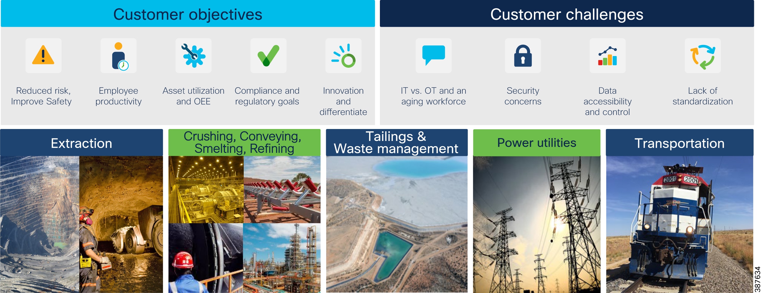
Objectives and Challenges in the Mining Industry
Mining Customer Objectives and Challenges below highlights key objectives and challenges of digitizing mining production environments, from extraction to transportation and several of the steps in between.
Figure 1 Mining Customer Objectives and Challenges
Mining Use-Cases and Requirements
Digitalization in Mining
With growing pressures on the global mining industry, achieving breakthrough performance in all areas of the mining life cycle is fundamental to staying profitable. Mining companies will have to re-think how they have been operating in the past and adapt a digital future to improve productivity, safety, and efficiency.
Digital technologies have the potential to unlock new ways of managing variability and enhancing productivity. As the skilled labor pool shrinks companies are seeking opportunities to better utilize their more experienced workers, and to gain new flexibility to meet future supply chain demands.
Connected devices and smart machines help capture real-time process information enabling better decision-making. Gaining deeper insights into equipment health and operations can dramatically improve asset productivity. Remote operation centers are the evolution to the digitization effort helping enable visibility, management, and remote command and control to allow for economies of scale.
The mine digitalization revolution and the development of technology has and will continue to enable huge improvements for mining operations. This requires a modern and standardized infrastructure that will support the digitalization process as well as openness and interoperability between different systems.
Benefits of Digitalization in Mining:
Safety Systems
Prioritizing safe, healthy, and sustainable operations with worker and environmental safety is the top priority. The ultimate goal is to achieve zero worker injuries and minimize human error. Autonomous, semi-autonomous, and remote operations are helping achieve this goal today by removing people from high-risk environments. Machine autonomy demands a highly available, deterministic, and secure network infrastructure upon which network-intensive mining systems and applications rely. Slope and seismic activity monitoring allow for production optimization while minimizing safety risk.
Tailing Ponds
Currently many mine operators monitor tailing ponds manually. Operations management send personnel to tailing ponds; however, prior approval is typically required for access. Acquiring approval for access can take time, as does the drive to and from the tailing pond which can take an hour in some facilities. Additionally, supervisors require that personnel check valves and place discharge hoses. Ultimately, a large amount of time is expended prior to the movement of any water or waste product.
Figure 2 Tailing Pond at an Open-Pit Mine

Enabling connectivity and visibility into water and waste flow from the processing plant to the tailing ponds will improve production efficiency, resource utilization, monitoring for safety, and environmental compliance. Being able to monitor valve positions remotely allows operators to proactively identify where waste would be delivered without having to dispatch personnel to visually inspect valve conditions along the lengthy pipes that run between the processing plant and the tailing ponds. This capability will speed up the waste management process and improve safety with the knowledge that waste is being sent to the correct location. Otherwise, waste could cause instability if sent to an incorrect tailing pond and may potentially lead to environmental impact.
Tailing dams require seismic and dam wall monitoring. Mobile mine workers want full coverage via remote access to production and corporate systems when working in and around tailing dams.
Dust control is another major concern around mines in general and at tailing areas specifically, because tailing ponds are made of very small particles of earth. Environmental impact is a major concern, as not only could dust have a negative impact on the environment but it also could result in large fines from the local environmental supervisory agencies. By automating dust control sprays and using video to demonstrate dust control, a mining operation can limit the financial impact from penalties imposed should dust-related issues occur. Other places where automated dust control is needed include ore heaps and bulk shipping ports.
Key networking capabilities required to support the mobility domain include:
■![]() Resilient, reliable, and mobile wireless networks to connect key assets and personnel
Resilient, reliable, and mobile wireless networks to connect key assets and personnel
■![]() Wireless backhaul and WAN technologies to interconnect the extraction zones to local sitewide operational services and Remote Operations Centers.
Wireless backhaul and WAN technologies to interconnect the extraction zones to local sitewide operational services and Remote Operations Centers.
Mobile Fleet Management Systems
Most mines today have some version of a mobile Fleet Management System (FMS) to provide equipment monitoring and dispatch. For these systems to work effectively, they require connectivity between mine equipment and mine operations software. These requirements often drive the business case behind the initial mine network deployment. Even in these initial wireless network deployments, it is very helpful to consider the planned operation of the mine since an increase in the scope of network usage implies more network requirements.
As use cases get more complex, the impact of network performance becomes increasingly critical to the operation of an industrial site. Increased demand is put on the network because field personnel come to rely on access to online systems and the new features of mobile fleet management. Eventually, the infrastructure becomes a must-have, nonnegotiable requirement to operate the industrial site.
Autonomous and Tele-Remote Operations
Traditionally, most heavy equipment operations in a mine are performed with an operator located within the mining equipment. Not only is this costly, but it also puts personnel into potentially hazardous situations such as equipment rolls or collisions. The capability of new industrial vehicles to drive autonomously or semi-autonomously has been a game changer for the mining industry.
Within mining operations, transportation from personnel housing to mine operator staging areas can take over an hour (one way). Workers might be required to wear special personal protective equipment (PPE), which requires a significant amount of time to maintain and change into. In some underground areas that are extremely dangerous and unstable, such as wet muck underground tunnels, or even in extremely hot or cold mine locations, mine personnel can be directly exposed to dangerous environments for only limited amounts of time.
News reports of self-driving cars on public roads have been increasing in recent years, but the technology is definitely struggling to keep up with the hype. Challenges include the large number of unpredictable conditions from undocumented aspects of the driving environment, other human drivers, and wildlife, just to name a few. In the mining environment, however, it’s feasible to control or document the conditions to an extent that driving autonomy is very much achievable and profitable.
Mining operations are driving toward fully autonomous operational models throughout the production chain. Removing humans that manually operate equipment in high-risk production areas will improve productivity, improve product quality, increase worker safety, and help reduce the overall cost of operations. Common use cases today involving autonomous vehicles and equipment are either fully automated, without any direct human interaction, or semi-automated, with equipment that is remotely operated and monitored. Remote operations centers can be located close to the mine site or located completely offsite and away from the mine.
Digital Dispatch
The first step in the evolution from manual to semi-automated or fully automated mining operations is digital dispatch. Digital dispatch processes connect mobile fleets to the mine network, thus allowing for proper route calculations and ensuring that operators unload the correct materials in the right spots, efficiently transporting high-grade ore to the crusher and appropriately delivering overburden to the correct dump. Digital dispatch requires connecting the mine fleet over a wireless network.
Semi-Autonomous Operations
Semi-autonomous machine operations include loaders in a one-to-one or one-to-many remote operator to machine ratio. One use case is a haul truck operator who can control a loader from inside the cab of the truck to load ore into their truck, thus eliminating the need for an additional operator who would be sitting idle the entire time that the truck is in transit. A ratio of one-to-one or one-to-many allows remote personnel to operate mining equipment from a safe location.
Likewise, autonomous trucks can haul resources from shovels or front-end loaders in a mine to a crusher area. When fully automated, trucks may continuously operate at optimum performance, thus reducing engine wear and improving tire performance and fuel efficiency. This reduces maintenance costs, reduces downtime, and increases productivity.
Reliable wireless network performance is critical to ensuring continuous equipment operations. Network personnel strive to minimize packet loss and wireless roam times to achieve optimal application performance. Any wired network issues, or prolonged wireless roam times can trigger the safety system that in-turn will result in the vehicle or equipment stopping, ultimately affecting productivity, reducing production, and incurring financial losses. The Cisco Ultra-Reliable Wireless Backhaul (CURWB) portfolio of fixed and mobility wireless solutions play an integral part in providing a high-performing, highly available, and secured wireless networking infrastructure for supporting autonomous operations within a mine.
Connecting the mine vehicle fleet to the production network allows Vehicle Intelligent Monitoring Systems (VIMS) to feed a large data analytics engine. Analysis of VIMS data by mine operators enables better equipment monitoring and proactive maintenance. Cisco’s solution helps mining companies improve predictive maintenance and provides visibility into issues such as problems with engine oil pressure or faulty cooling systems before they escalate. Discovering and addressing these issues before a failure occurs can save up to 72 hours of downtime or a costly engine replacement.
As an example, consider the conversion of haul trucks to autonomous operation in an open pit mine. Removing drivers from haul trucks has an immediate reduction in personnel cost, since only a few people are required to supervise the operation that required dozens of drivers previously. Safety in the mine is also increased when the number of people in hazardous environments is dramatically reduced. Without the human driver in charge, the truck no longer needs to stop for lunch breaks, shift changes, or other human initiated stops. Once in production, it’s also become evident that autonomous systems are less harsh in the operation of the vehicles, resulting in fewer maintenance issues.
Other considerations that are less documented include predictive maintenance savings by leveraging access to more vehicle data or more-efficient driving paths that are possible for trucks but not friendly to human drivers.
The benefits of vehicle autonomy are so compelling that most mining companies have an active autonomous vehicle project or are considering it. All of these projects have implications to the network infrastructure, and each of them is centered around a specific autonomous driving software platform.
The key networking capabilities required to support the mobility domain include:
Resilient, reliable, and mobile wireless networks to connect key assets and personnel
Wireless backhaul and WAN technologies to interconnect the extraction zones to local sitewide operational services and Remote Operations Centers.
Software Applications
The software systems used to oversee and control the autonomous mine vehicle environment are largely owned by the mine vehicle manufacturers, with third-party solutions starting to emerge. For example, in open pit mining, Caterpillar has been deploying their CAT(R) MineStar(R) application suite for a number of years.
The application suite is made up of two parts: first, the user interface for the customer’s autonomous or tele-remote operations center, and second, a software component in every vehicle that is allowed to enter the autonomous zone. Truck software components provide location and other vehicle-specific data to the central system to help with decision-making about positioning, route, and speed instructions.
The equipment must be in continuous communication with the central system for position, route, speed, and other instructions.
At an autonomous operations center, a large wall screen shows a map of the autonomous zone’s geographic features and all the real-time vehicle locations in the zone. The vehicle status is evident by the color of the vehicle icon and any other relevant information that may help in managing the system.
Routing and speed decisions are primarily made by what is known in the digital version of the autonomous zone. The geographic features are entered into the zone by the builder role. One or more builders are present in the zone during production to ensure that any new geographic features are added to the digital representation as soon as possible. All vehicle data is dynamically updated in the digital world by the software onboard each vehicle. If the digital world doesn’t match the physical world, there are safety mechanisms like lidar, radar, and other technologies that are used to stop autonomous vehicles if a safety issue is evident. One of the safety mechanisms is triggered when network connectivity is disrupted between any vehicle and the central system. A reliable network infrastructure is essential to the success of this use case.
Autonomous Dozing
Dozing can be done in several ways. The traditional way is to have an operator inside the cab driving the dozer. Several times a dozer is used to compact an area or to move in a repetitive manner to move some material. When this is the case autonomy can play a big role in executing the repetitive motions. An operator can remotely move an automated dozer from one job to the other and this way a single operator can efficiently control several dozers. In addition to working more efficiently, operators also experience less physical fatigue thanks to their location in a comfortable office environment.
Autonomous Haulage
Likewise, autonomous trucks can haul resources from shovels or front-end loaders in a mine to a crusher area. When fully automated, trucks may continuously operate at optimum performance, thus reducing engine wear, improving tire performance and fuel efficiency. This reduces maintenance costs and downtime and increases productivity.
Autonomous Drilling
Accurate drilling and blasting help make every other aspect of a mining operation smoother, safer and more productive. Even minor deviations from the pattern can have a big impact, with unevenly blasted material that is harder and more costly to handle, resulting in higher cost per ton for the entire operation.
With high precision and more accurate depth tracking, autonomous drills can work far more accurately to plan. That means more accurate blasting and better-shot material, less time spent removing overburden, and higher productivity.
Most importantly, an autonomous drill removes operators from the dust, vibration and other hazardous conditions that surround a working drill — and keeps them safely away from blasting areas. No operator is safer than one who is overseeing the machine from a comfortable location far from the hazards the machine itself faces.
Advantages of Autonomous / Semi-Autonomous Mining Operations
■![]() Higher Operational Efficiency: Programmed loader and truck cycles enable fast, precise operation that is controlled within equipment limitations. Bottlenecks are reduced for material handling, cycle times, and productivity.
Higher Operational Efficiency: Programmed loader and truck cycles enable fast, precise operation that is controlled within equipment limitations. Bottlenecks are reduced for material handling, cycle times, and productivity.
■![]() 24 x 7 Operations: Ore extraction can proceed in round-the-clock shifts with minimal transition time, thereby dramatically improving productivity and daily output.
24 x 7 Operations: Ore extraction can proceed in round-the-clock shifts with minimal transition time, thereby dramatically improving productivity and daily output.
■![]() Improved Worker Safety: Improvements in worker safety and health are realized by connecting autonomous vehicles, and other equipment, which can be operated remotely from a safe location with no risk to workers.
Improved Worker Safety: Improvements in worker safety and health are realized by connecting autonomous vehicles, and other equipment, which can be operated remotely from a safe location with no risk to workers.
■![]() Improved Mine Safety: Fewer workers are required in mining pit. Depending on the level of automation, these workers could be limited to maintenance and other general functions.
Improved Mine Safety: Fewer workers are required in mining pit. Depending on the level of automation, these workers could be limited to maintenance and other general functions.
■![]() Improved equipment utilization: Vehicle automation provides more detailed telemetry on vehicle health and status, thereby facilitating predictive and better preventive maintenance scheduling and lower risk of incidents and abuse. Vehicle automation increases productivity and decreases vehicle maintenance costs.
Improved equipment utilization: Vehicle automation provides more detailed telemetry on vehicle health and status, thereby facilitating predictive and better preventive maintenance scheduling and lower risk of incidents and abuse. Vehicle automation increases productivity and decreases vehicle maintenance costs.
■![]() Ability to attract tech-savvy young talent pool: Embracing technology has the added benefit of helping mining operations attract a new generation of tech-savvy talent by moving labor-intensive jobs out of the mine and into remote control centers. Fewer risks and safer conditions expand the pool of candidates to operate mine vehicles.
Ability to attract tech-savvy young talent pool: Embracing technology has the added benefit of helping mining operations attract a new generation of tech-savvy talent by moving labor-intensive jobs out of the mine and into remote control centers. Fewer risks and safer conditions expand the pool of candidates to operate mine vehicles.
Fleet Management Network Requirements
■![]() Must support IP connectivity from mine vehicles or other assets to a local server
Must support IP connectivity from mine vehicles or other assets to a local server
■![]() Minimum Throughput capability 500 kbps
Minimum Throughput capability 500 kbps
■![]() Minimum client radio connection rate 2 Mbps
Minimum client radio connection rate 2 Mbps
■![]() Must support wireless roaming < 250 mSec roaming time
Must support wireless roaming < 250 mSec roaming time
■![]() Maximum loss of connectivity 3 seconds
Maximum loss of connectivity 3 seconds
■![]() Must support the following protocols:
Must support the following protocols:
Autonomous Haulage System (AHS) Network Requirements
■![]() Must support IP connectivity from mine vehicles or other assets to a local server.
Must support IP connectivity from mine vehicles or other assets to a local server.
■![]() Consecutive packet loss or out of order packets <= 2
Consecutive packet loss or out of order packets <= 2
■![]() Minimum Throughput capability 6 Mbps
Minimum Throughput capability 6 Mbps
■![]() Minimum client radio connection rate 6 Mbps
Minimum client radio connection rate 6 Mbps
■![]() Must support wireless roaming <250 mSec roaming time
Must support wireless roaming <250 mSec roaming time
■![]() Maximum loss of connectivity 2 seconds
Maximum loss of connectivity 2 seconds
■![]() Must support the following protocols:
Must support the following protocols:
Remote Command Network Requirements
■![]() Must support IP connectivity from mine vehicles or other assets to a local server.
Must support IP connectivity from mine vehicles or other assets to a local server.
■![]() Minimum Throughput capability 10 Mbps
Minimum Throughput capability 10 Mbps
■![]() Minimum client radio connection rate 24 Mbps
Minimum client radio connection rate 24 Mbps
■![]() Consecutive packet loss or out of order packets <= 2
Consecutive packet loss or out of order packets <= 2
■![]() Must support wireless roaming < 250 mSec roaming time
Must support wireless roaming < 250 mSec roaming time
Caterpillar MineStar® Command for Hauling
Cat® Command for Hauling is an autonomous haulage solution that can increase your safety, efficiency, productivity and more. Trucks can travel to the loading and dump points, fueling stations, haul roads and more — all without the need for an operator to step on board.
Command for Hauling takes advantage of the most sophisticated technologies available to enable Cat® autonomous haul trucks to work safely and productively on busy mine sites. More than just an operator-free equipment system, Command for hauling is a complete, next-generation haulage solution that delivers solid, bottom-line benefits for miners who need to work in difficult or inaccessible locations. Highly advanced safety systems enable Cat autonomous haul trucks to operate reliably around other mining equipment, light vehicles, and site employees.
Command for Hauling integrates with all other Cat® MineStar® System capability sets for assignment, control, and machine health monitoring.
Command for Hauling – Network Requirements
Command for Hauling requires continual, uninterrupted communication with the moving machines as they traverse the zone of operations. The underpinning network technology requirement of Command for Hauling is the reliable transmission and reception of multicast, unicast and broadcast packets at all points in the area of operations. In order to operate most effectively, the autonomous trucks need to continually update their location and receive a stream of position updates of the other site awareness machines throughout the mine. Additionally, all machines within the AOZ must reliably receive GPS correction broadcasts for positioning accuracy.
Network design challenges exist in the handoff from one area of coverage to another as these algorithms must be robust and efficient. Support for multicast traffic during handoffs is also a key requirement.
Cat® MineStar® Command for Hauling takes advantage of the most sophisticated technologies available to deliver a next-gen haulage solution - one that boosts safety, productivity, and availability on busy mine sites, especially those in difficult or remote locations.
Command for Hauling has forever changed how mining companies move material — allowing them to haul more efficiently with near-continuous operation and move more with fewer people on site. Proven on diverse operations around the globe, Command for Hauling is opening new possibilities for mines of all sizes, complexities and locations.
■![]() Enhances safety by removing operators from hazardous or remote sites.
Enhances safety by removing operators from hazardous or remote sites.
■![]() Reduces costs for employee infrastructure and travel to remote sites.
Reduces costs for employee infrastructure and travel to remote sites.
■![]() Improves efficiency, enables consistency in operations and provides near-continuous operation through the reduction of operational delays.
Improves efficiency, enables consistency in operations and provides near-continuous operation through the reduction of operational delays.
■![]() Improves fuel efficiency and component life.
Improves fuel efficiency and component life.
■![]() Prevents machine damage and downtime due to misuse and overloading.
Prevents machine damage and downtime due to misuse and overloading.
■![]() Allows the instant alteration or redesign of mine maps to meet changing operational needs.
Allows the instant alteration or redesign of mine maps to meet changing operational needs.
■![]() Enables advanced assignment and tracking from a central location.
Enables advanced assignment and tracking from a central location.
■![]() Alerts maintenance personnel to machine faults, enabling repairs before failure and reducing downtime.
Alerts maintenance personnel to machine faults, enabling repairs before failure and reducing downtime.
System Requirements
It is important to note that Command for Hauling requirements must form the basis of the network design criteria and not compromise requirements to other applications. The network traffic from Command for Hauling should be protected through appropriate quality of service or segregation.
Quality of Service (QoS) Requirements
A quality of service (QoS) function to provide priority to Command for Hauling over background traffic will be required if other applications requiring significant bandwidth are running on the same network. In these cases, Command for Hauling traffic must be prioritized in the top queues.
Security Requirements
The site communications infrastructure must be protected from access by unauthorized or unqualified individuals and applications through industry best practices for securing mission critical data networks including but not limited to the following:
■![]() Access to configuration of all network components must be limited to authenticated, authorized network management and support personnel.
Access to configuration of all network components must be limited to authenticated, authorized network management and support personnel.
■![]() Adequate security firewalls must be in place to protect against unauthorized access via public networks.
Adequate security firewalls must be in place to protect against unauthorized access via public networks.
■![]() Qualified Caterpillar and Caterpillar dealer technical support personnel must be allowed appropriate access to the network to administer and support the Command for Hauling system.
Qualified Caterpillar and Caterpillar dealer technical support personnel must be allowed appropriate access to the network to administer and support the Command for Hauling system.
Network Management and Maintenance Requirements
The wireless RF environment must frequently be measured and quality maintained to assure coverage. In an active mining environment, the RF characteristics change as the mine moves or terrain features are removed. It is strongly suggested that responsibility for the wireless network coverage and availability is well integrated with the mine operations so changes can be anticipated and responded to quickly by surveying and altering the coverage as necessary.
Understanding the health of the network and equipping the network support team with the right tools is important to getting the most productivity from Command products. Wi-Fi spectrum analyzer to locate and mitigate interference is a key tool.
Chapter 2: CURWB Architecture to support Autonomous and Tele-Remote Operations within Open-Pit Mines
This chapter starts by providing an overview of the Cisco Ultra-Reliable Wireless Backhaul (CURWB) technology, the wired and wireless network components needed to build out the solution, the high-level and low-level architecture to support autonomous and tele-remote operations within an Open-Pit mine, followed by some design best-practices around High-availability, QoS and Security.
Cisco Ultra-Reliable Wireless Backhaul (CURWB) Overview
Figure 3 Key CURWB capabilities
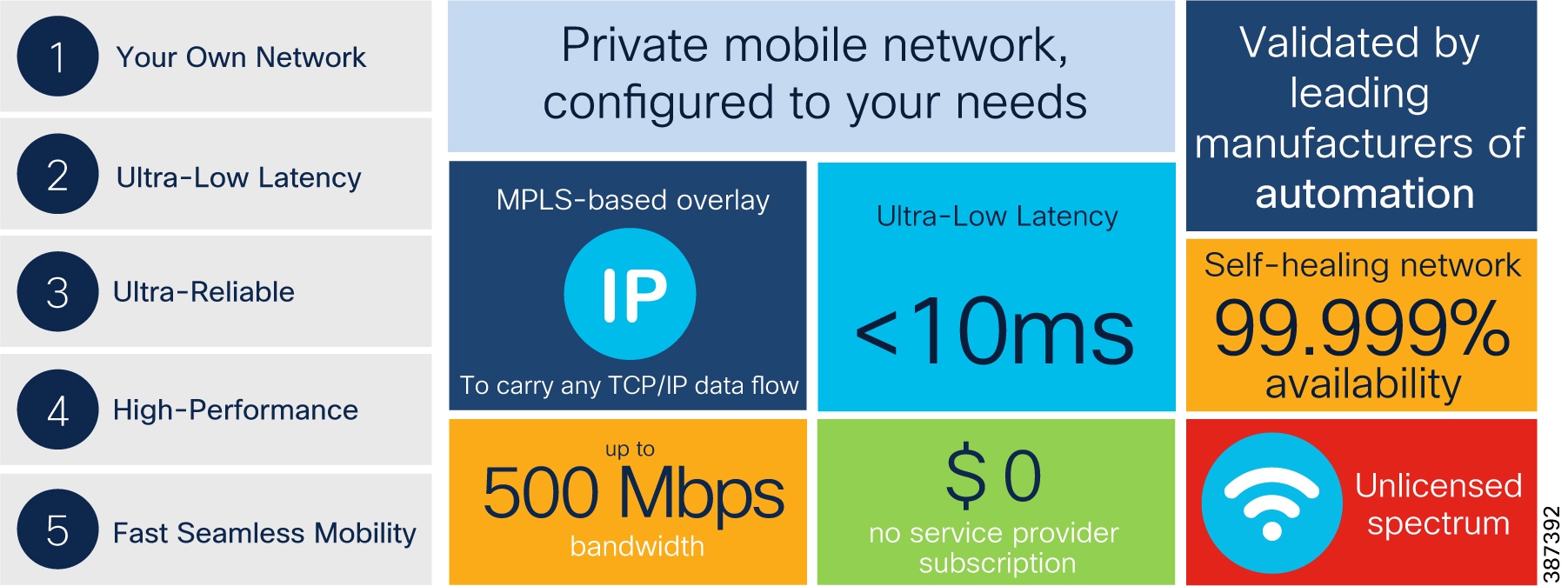
Key technical requirement met by CURWB for the Mining Vertical:
■![]() Supports PROFINET and CIP safety
Supports PROFINET and CIP safety
■![]() Ultra-Low latency of < 10 mSec
Ultra-Low latency of < 10 mSec
■![]() Seamless roaming (handoff) - Multi-frequency capability with 0 m/s handoff
Seamless roaming (handoff) - Multi-frequency capability with 0 m/s handoff
CURWB - Key Technology Pillars
Three key technologies underlay the foundation for the Cisco Ultra-Reliable Wireless Backhaul (CURWB) solution.
■![]() Prodigy 2.0: MPLS-based transmission protocol built to overcome the limits of standard wireless protocols.
Prodigy 2.0: MPLS-based transmission protocol built to overcome the limits of standard wireless protocols.
■![]() Fluidity: Proprietary fast-roaming algorithm for vehicle-to-wayside communication with a 0 mSec roam delay and no roam loss for speeds up to 200 Mph or 360 km/hour.
Fluidity: Proprietary fast-roaming algorithm for vehicle-to-wayside communication with a 0 mSec roam delay and no roam loss for speeds up to 200 Mph or 360 km/hour.
■![]() TITAN: Proprietary fast-failover high-availability mechanism that provides hardware redundancy and carrier-grade availability.
TITAN: Proprietary fast-failover high-availability mechanism that provides hardware redundancy and carrier-grade availability.
Prodigy 2.0 – MPLS Overlay
CURWB uses the proprietary wireless-based MPLS transmission protocol Prodigy to discover and create label-switched paths (LSPs) between mesh-point radios and mesh end(s). Prodigy helps with making the wireless mesh networks resilient and helps for both Fixed as well as Mobility networks. MPLS provides an end-to-end packet delivery service operating between Layer 2 and 3 of the OSI network stack. It relies on label identifiers, rather than the network destination address as in traditional IP routing, to determine the sequence of nodes to be traversed to reach the end of the path.
Fluidity
Fluidity enables a vehicle that is moving between multiple infrastructure APs to maintain end-to-end connectivity with seamless handoff between APs. Vehicle radios negotiate with the infrastructure APs and form a new wireless connection to a more favorable infrastructure AP with better signal quality before breaking or losing its currently active wireless connection.
TITAN – Hardware Redundancy and High-Availability
TITAN is a proprietary fast-failover function providing high-availability and protection against hardware failures. The feature virtually guarantees uninterrupted service for mission-critical applications where safety and/or operations would otherwise be compromised by failure of a single radio or gateway device. Leveraging an MPLS-based protocol, TITAN is able to achieve device failovers within 500 mSec within both L2 and L3 networks.
Wired Network Components
Cisco Catalyst 9300 Access Layer Switch
Figure 4 Cisco Catalyst 9300 Access Layer Switch
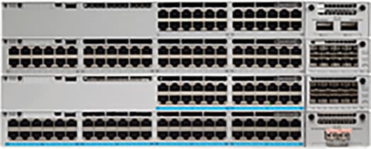
The Cisco Catalyst 9300 Series Switches are the next generation of enterprise-class, stackable, aggregation layer switches. They provide full convergence between wired and wireless networks on a single platform.
■![]() Delivers 480 Gbps stacking bandwidth capacity.
Delivers 480 Gbps stacking bandwidth capacity.
■![]() Flexible uplinks: Cisco Multigigabit, 1 Gbps, 10 Gbps, 25 Gbps, and 40 Gbps. Fixed (C9300L) and modular (C9300) options.
Flexible uplinks: Cisco Multigigabit, 1 Gbps, 10 Gbps, 25 Gbps, and 40 Gbps. Fixed (C9300L) and modular (C9300) options.
■![]() Flexible downlinks: Cisco Multigigabit, 5 Gbps, 2.5 Gbps, or 1 Gbps copper, or 1 Gbps fiber. Perpetual Cisco UPOE+, Cisco UPOE and PoE+ options.
Flexible downlinks: Cisco Multigigabit, 5 Gbps, 2.5 Gbps, or 1 Gbps copper, or 1 Gbps fiber. Perpetual Cisco UPOE+, Cisco UPOE and PoE+ options.
■![]() Supports ETA, AVB, Cisco Umbrella cloud security, MACsec-256 encryption, hot patching, NFS/ SSO, redundant power and fans.
Supports ETA, AVB, Cisco Umbrella cloud security, MACsec-256 encryption, hot patching, NFS/ SSO, redundant power and fans.
Cat-9300 Datasheet and switch model selector: https://www.cisco.com/c/en/us/products/collateral/switches/catalyst-9300-series-switches/nb-06-cat9300-ser-data-sheet-cte-en.html
Catalyst 9500 Distribution/Core Layer Switch
Figure 5 Catalyst 9500 Distribution/Core Layer Switch
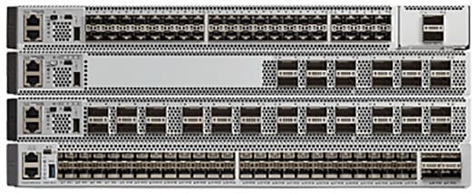
The Cisco Catalyst 9500 Series Switches are the next generation of enterprise-class, stackable, core layer switches.
■![]() 4-core x86, 2.4-GHz CPU, 16-GB DDR4 memory, and 16-GB internal storage
4-core x86, 2.4-GHz CPU, 16-GB DDR4 memory, and 16-GB internal storage
■![]() Up to 6.4-Tbps switching capacity with up to 2 Bpps of forwarding performance
Up to 6.4-Tbps switching capacity with up to 2 Bpps of forwarding performance
■![]() Up to 32 nonblocking 100 Gigabit Ethernet QSFP28 ports
Up to 32 nonblocking 100 Gigabit Ethernet QSFP28 ports
■![]() Up to 32 nonblocking 40 Gigabit Ethernet QSFP+ ports
Up to 32 nonblocking 40 Gigabit Ethernet QSFP+ ports
■![]() Up to 48 nonblocking 25 Gigabit Ethernet SFP28 ports
Up to 48 nonblocking 25 Gigabit Ethernet SFP28 ports
■![]() Up to 48 nonblocking 10 Gigabit Ethernet SFP+ ports
Up to 48 nonblocking 10 Gigabit Ethernet SFP+ ports
Cat-9500 Datasheet and switch model selector: https://www.cisco.com/c/en/us/products/collateral/switches/catalyst-9500-series-switches/nb-06-cat9500-ser-data-sheet-cte-en.html
Cisco IE3x00 Rugged Industrial Switches
Figure 6 Cisco IE3x00 Rugged Industrial Switches
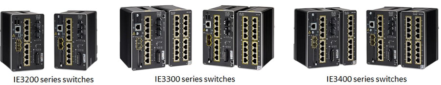
Cisco Catalyst IE3200 Rugged Series switches feature advanced, full Gigabit Ethernet with a modular, future-proof design. Expandable up to 26 ports in a compact form factor, these rugged switches are optimized for size, power, and performance.
Cisco Catalyst IE3300 Rugged Series switches deliver high-speed up to 10 Gigabit Ethernet connectivity in a compact form factor, and are designed for a wide range of industrial applications where hardened products are required. The modular design of the Cisco Catalyst IE3300 Rugged Series offers the flexibility to expand to up to 26 ports of Gigabit Ethernet or up to 24 ports of Gigabit Ethernet and 2 ports of 10 Gigabit (10G) Ethernet with a range of expansion module options.
The Cisco Catalyst IE3400 Rugged Series switches deliver advanced, high-speed Gigabit Ethernet connectivity in a compact form factor, and are designed for a wide range of industrial applications where hardened products are required. The modular design of the Cisco Catalyst IE3400 Rugged Series offers the flexibility to expand up to 26 ports of Gigabit Ethernet with a range of expansion module options.
All of the above platforms are built to withstand harsh environments in manufacturing, energy, ports and terminals, transportation, mining, smart cities, and oil and gas.
These switches run Cisco IOS® XE, a next-generation operating system with built-in security and trust, featuring secure boot, image signing, and the Cisco® Trust anchor module.
Cisco IE3400H Heavy Duty Industrial Switch
Figure 7 Cisco IE3400H Heavy Duty Industrial Switch

The Cisco Catalyst IE3400 Heavy Duty Series switches deliver the advanced capabilities similar to the Cisco Catalyst IE3400 Rugged Series in environments that have heavy exposure to dust and water. These switches are available with 8, 16, or 24 Fast Ethernet (D-coded) or Gigabit Ethernet (X-coded) M12 interfaces. The switches can be wall mounted and deployed without a housing cabinet.
Cisco IE3400H Datasheet: https://www.cisco.com/c/en/us/products/collateral/switches/catalyst-ie3400-heavy-duty-series/datasheet-c78-742313.html
Note: Due to the high-level of vibration on Mining autonomous vehicles it is highly recommended to use the IE3400H series of switches since they are more rugged and can better handle vibration.
Note: The IE3400H does not support PoE so the CURWB radios onboard the vehicle will need to be powered using DC power.
Wireless Network Components
CURWB Mesh End Gateway
All Fluidity / fixed infrastructure deployments need a mesh end. It functions as a gateway between wireless + wired. It is highly recommended that all systems using Fluidity use a redundant pair of mesh end gateways to terminate the MPLS tunnels, aggregate traffic and act as interface between the wired and wireless network. Mesh End gateways can also be thought of as MPLS label edge routers (LERs) on the infrastructure network. The Mesh End gateway is responsible for encapsulating the traffic coming in from the wired network into the Fluidity overlay network using MPLS and de-encapsulating MPLS and delivering standard datagrams onto the wired network.
CURWB gateways are rugged, industrial grade network appliances that make setup and management of medium and large-scale CURWB Fluidity and Fixed Infrastructure deployments fast and easy.
CURWB Gateway models comparison
Figure 8 FM1000 and FM10000 Mesh End Gateway
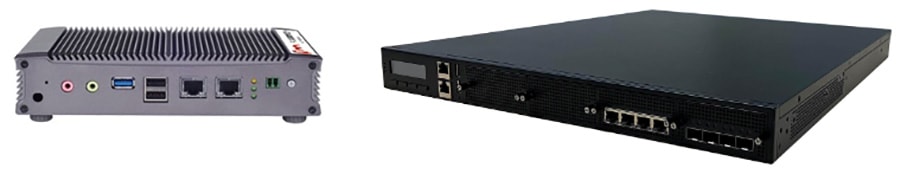
Note: A CURWB radio such as an FM3500 can also be configured as a Mesh End gateway. It can support throughput up to 250 Mbps.
CURWB FM3200 Base Radio Unit
A rugged designed, long lasting performance radio, with an integrated 120-degree sector antenna, supports point-to-point, point-to-multipoint, mesh and mobility networks with a real throughput of up to 150Mbps. Within a mining deployment this radio is optimal to be deployed on Communications Towers that are acting as a hub for PtMP deployments to aggregate incoming traffic from multiple trailers.
Figure 9 FM3200 Base Radio Unit
FM3200 Base datasheet: https://www.cisco.com/c/en/us/products/collateral/wireless/ultra-reliable-wireless-backhaul/datasheet-c78-744548.html
CURWB FM4200 Fiber Radio Unit
Figure 10 FM4200 Fiber Radio Unit

The Cisco FM4200 Fiber is a high-performance mobility-communications radio transceiver, designed to deliver fast and stable connectivity particularly for mission-critical use cases and in extreme environments. Within a mining deployment, an FM4200 Fiber radio unit can be used as the backhaul radio (spoke radio for a PtP or PtMP fixed wireless deployment) on mining Trailers or Poles.
FM4200 Fiber datasheet: https://www.cisco.com/c/en/us/products/collateral/wireless/ultra-reliable-wireless-backhaul/datasheet-c78-744550.html
CURWB FM4500 Radio Unit
Figure 11 FM4500 MOBI and FM4500 Fiber Radio Unit
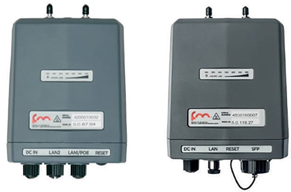
The FM4500 MOBI comes in a rugged die cast aluminum housing that has been purpose built for harsh environments such as those found within the Mining Vertical. It consists of industrial-grade anti-vibration M12 ports and QMA connector. Optionally, one can also order the fiber-enabled FM4500 FIBER which supports a fiber port with an XCO connector.
The Ethernet model has 2 x 10/100/1000 M12 ports. The Fiber model has 1 x Dual LC ruggedized SFP XCO connector (transceiver not included) and 1 x 10/100/1000 M12 port. The radio can either be powered using PoE+ output from a switch or 48V DC input from an onboard power source.
Note: The radio can also be powered using both DC power and PoE at the same time. So each power source acts as a backup for the other one.
The FM4500 MOBI is the recommended radio model to be deployed on board the vehicles, since it is vibration resistant. Within a mine deployment this is also the recommended radio model to be deployed as an access radio providing RF coverage to the autonomous vehicles within the access layer.
Cisco FM4500 MOBI data sheet: https://www.cisco.com/c/en/us/products/collateral/wireless/ultra-reliable-wireless-backhaul/datasheet-c78-744552.html
Cisco FM4500 FIBER data sheet: https://www.cisco.com/c/en/us/products/collateral/wireless/ultra-reliable-wireless-backhaul/datasheet-c78-744551.html
CURWB radios SFP compatibility matrix: https://tmgmatrix.cisco.com/?npid=4601&npid=4602&npid=5001
FM-OMNI-5-KIT Antenna
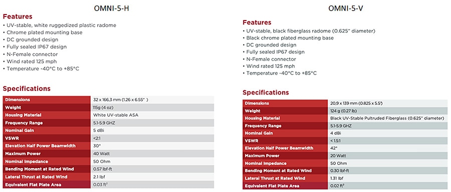
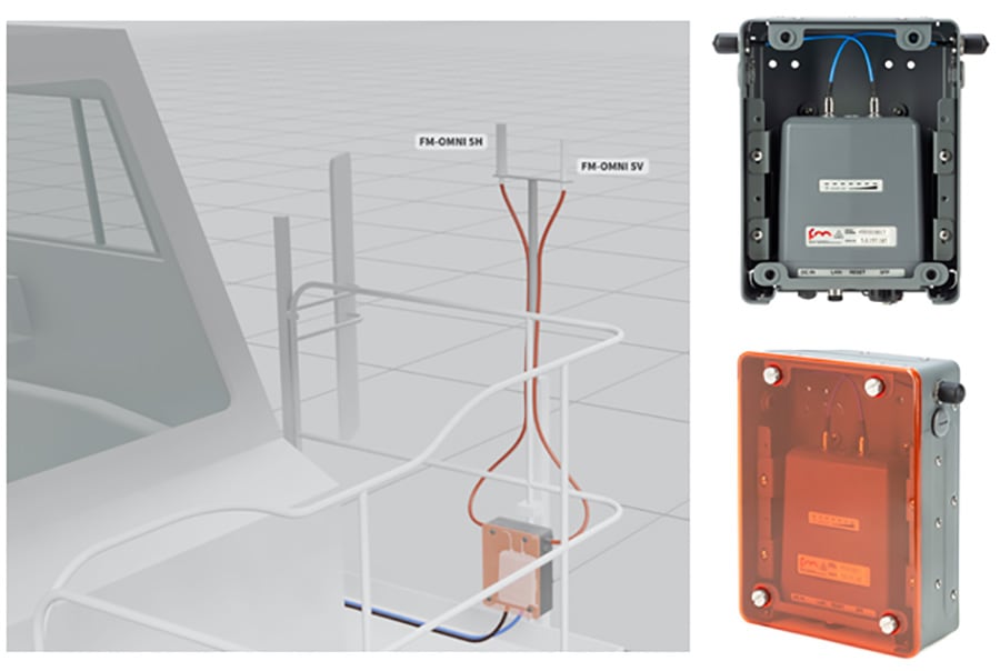
The FM-OMNI-5-KIT antenna consists of two antennas, a FM-OMNI-5-H which is a horizontally polarized antenna and an FM-OMNI-5-V which is a vertically polarized antenna. FM-OMNI-5-H horizontally polarized omnidirectional antennas are designed for long-lasting operation with outdoor access points. The FM-OMNI-5-V vertically polarized omnidirectional design utilizes a linear array, encapsulated in a heavy-duty fiberglass radome with a thick-walled mounting base for reliable, long-term use.
This rugged design of the above antennas withstands harsh environments, making the antennas ideal for Industrial Wireless applications. The antennas are DC grounded for ESD protection of radio components.
Figure 12 FM-OMNI-5-KIT Antenna Specifications
FM-Horn-90 Antenna
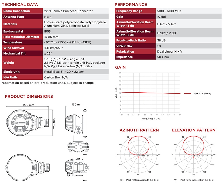
The FM-Horn-90 is a connectorized symmetrical horn antenna with carrier class performance. The FM-Horn-90 antenna offers unique RF performance in a very compact package. Scalar horn antennas have symmetrical beams with identical patterns in the Vertical and Horizontal planes. Extremely small side lobes result in greatly decreased interference. FM-Horn-90 antennas are ideal for covering areas with close in clients where null zone issues occur. High density AP clusters and radio co-location is now practical due to its radiation pattern and a compact size. The FM-Horn-90 antenna is equipped with N-female connectors.
Figure 13 FM-Horn-90 Specifications
FM-SECTOR-90-HV
FM-SECTOR-90-HV are addressing customer requirements for exceptional RF performance, an innovative patent pending Back-Shield™ system of frequency selective reflectors that are incorporated into the antenna structure to attenuate side lobes and backside near field radiation. All FM-SECTOR-90-HV sectors are designed with independent horizontal and vertical polarization antenna elements for unmatched RF performance.
Figure 14 FM-Sector-90-HV Antenna Specifications
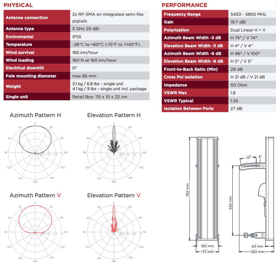
The FM-Sector-90-HV is a sector antenna that provides 90-degrees of coverage and can be used with either the FM3200 ENDO or the FM3500 on the communications towers for PtP or PtMP deployments.
FM-PANEL-19 Antenna
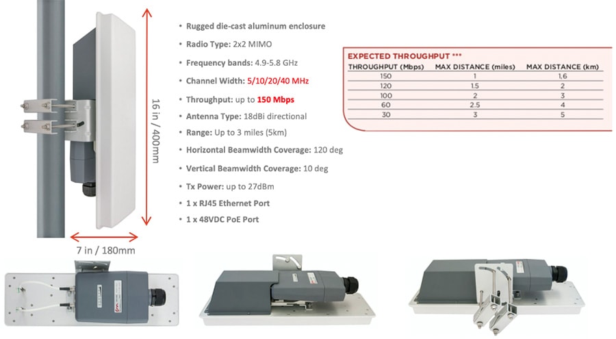
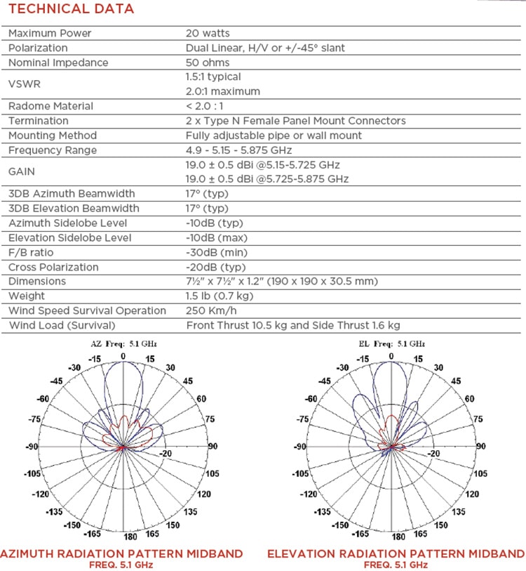
The FM-PANEL-19 is a dual-polarized Directional Panel Antenna with a gain of 19 dBi and is suitable for use in CURWB PtP and PtMP deployments. Within a mining deployment these can be deployed along with CURWB backhaul radios on trailers.
Figure 15 FM-PANEL-19 Antenna Specifications
FM-PANEL-22 Antenna
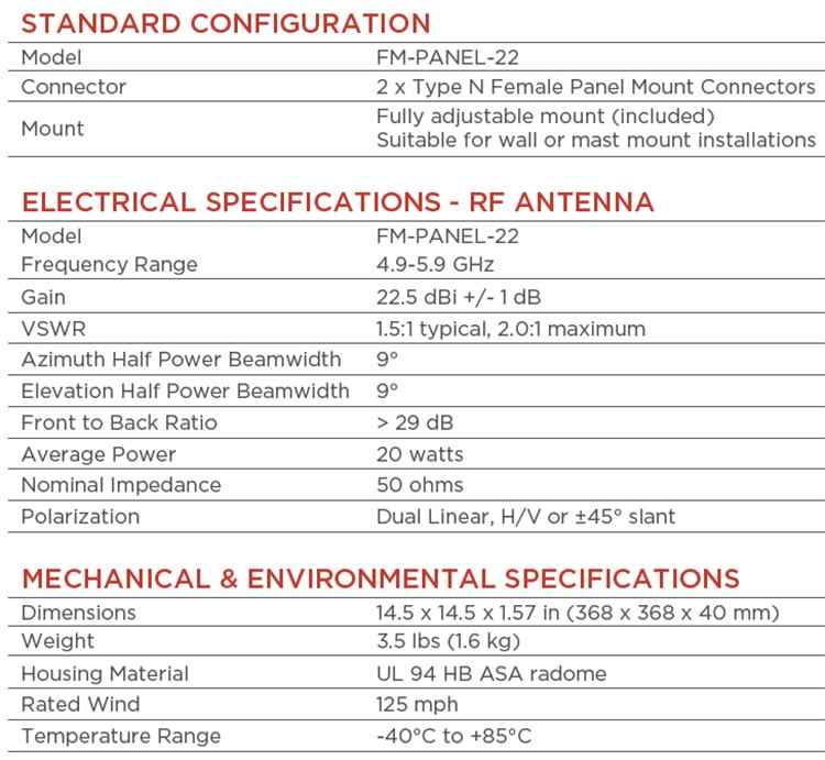
The FM-PANEL-22 is a dual-polarized Directional Panel Antenna with a gain of 22 dBi and is suitable for use in CURWB PtP and PtMP deployments. Within a mining deployment these can be deployed along with CURWB backhaul radios on trailers.
Figure 16 FM-PANEL-22 Antenna Specifications
FM-Shield Ruggedized Enclosure
The FM-SHIELD is a proprietary ruggedized enclosure designed to ensure long-term durability and reliability of radios that are installed in outdoor environments.
If a 3200-series, 3500 ENDO, 4200-series or 4500-series radio is installed in outdoor conditions, it is compulsory to install the radio inside an FM-SHIELD. It provides additional protection from impact, salt air and water.
■![]() Steel protective enclosure with Polycarbonate cover, designed to protect against high-pressure water spray and impacts from heavy, fast-moving objects.
Steel protective enclosure with Polycarbonate cover, designed to protect against high-pressure water spray and impacts from heavy, fast-moving objects.
■![]() Proven in high-vibration environments, including all vehicles operated in a terminal environment.
Proven in high-vibration environments, including all vehicles operated in a terminal environment.
■![]() N-Female antenna connectors for easy integration, and minimal RF signal loss.
N-Female antenna connectors for easy integration, and minimal RF signal loss.
■![]() Designed for installation within automation cabinets and on vehicle hand railings, antenna poles, can be installed in either a horizontal or vertical position.
Designed for installation within automation cabinets and on vehicle hand railings, antenna poles, can be installed in either a horizontal or vertical position.
■![]() Semi-transparent front panel with self-retaining screws for easy inspection.
Semi-transparent front panel with self-retaining screws for easy inspection.
Figure 17 FM-Shield Ruggedized Enclosure
RACER
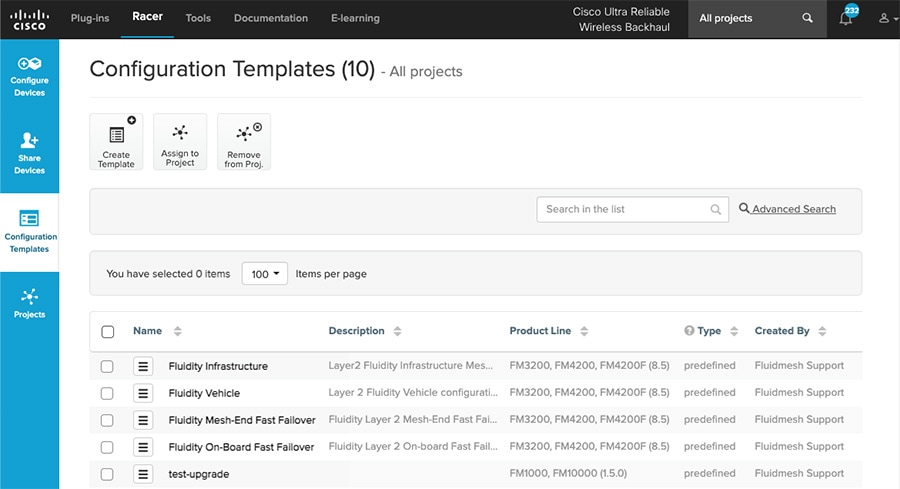
CURWB RACER is a centralized cloud-hosted server that can be used for provisioning of the entire CURWB system including configuration, firmware upgrade, and plug-in activation. It allows all the radio configuration to be done in a single pane and uploaded to the radios in real time or offline. RACER supports almost all the configuration options (basic and advanced).
RACER can be used to create configuration templates, fill in the template with the required parameter values to create radio configurations, and apply them to multiple CURWB devices of the same type. Configurations created in RACER can be applied to the radio in either online mode (if the CURWB devices have Internet access) or offline mode (if the CURWB devices have no Internet access). The advantage of using RACER is that along with the device configuration it also upgrades the firmware to the latest version available and also applies the configured plug-ins. This is the preferred method for configuring CURWB devices for any size deployment.
Figure 18 RACER Cloud-Hosted CURWB Configuration Tool
Note: Refer to the RACER section within the Implementation Guide below for step-by-step instructions on how to use RACER to create the appropriate CURWB radio configuration templates and configuring the CURWB radio devices.
FM-Monitor – Centralized Management of CURWB Infrastructure
FM-Monitor is a network-wide, on-premises monitoring dashboard, allowing any CURWB customer to proactively maintain and monitor one or multiple wireless OT networks. FM-Monitor displays data and situational alerts from every CURWB device in a network, in real time.
FM-Monitor supports fixed and roaming network architectures and allows easier end-to-end troubleshooting. It can be operated as a standalone system or in parallel with a sitewide Simple Network Management Protocol (SNMP) monitoring tool. It is designed to support network installations used in smart cities, rail, mining, ports and terminals, entertainment, smart factories, and military applications.
Note: This document does not provide the setup or configuration instructions for FM Monitor. For more information, refer to the FM Monitor documentation page at the following URL:
https://www.cisco.com/c/en/us/support/wireless/ultra-reliable-wireless-backhaul/series.html#~tab-documents
■![]() On-premises monitoring tool for CURWB networks
On-premises monitoring tool for CURWB networks
■![]() Wizard setup for quick and easy installation and deployment
Wizard setup for quick and easy installation and deployment
■![]() Real-time dashboard displaying uptime, throughput, latency, jitter, and other network KPIs
Real-time dashboard displaying uptime, throughput, latency, jitter, and other network KPIs
■![]() Customizable section view to easily check groups of radios
Customizable section view to easily check groups of radios
■![]() Customizable monitoring alerts for prompt response
Customizable monitoring alerts for prompt response
■![]() Radio-by-radio data logging with a minimum sampling interval of 300 mSec
Radio-by-radio data logging with a minimum sampling interval of 300 mSec
■![]() Real-time radio configuration display for quick and accurate troubleshooting
Real-time radio configuration display for quick and accurate troubleshooting
■![]() Side-by-side comparison of radio KPIs over time and vehicle position
Side-by-side comparison of radio KPIs over time and vehicle position
■![]() Ability to export logs to a Syslog server
Ability to export logs to a Syslog server
One of the biggest advantages of FM-Monitor is the ability to configure alerts for a group of radios based on certain KPIs. Imagine needing to support an application mix of Automation and CCTV. The set of radios supporting the Automation application can be grouped and alarms configured for KPIs such as latency, jitter, RSSI, etc. while the group of radios supporting the CCTV network can have alarms configured using different KPIs such as Link Error Rate (LER), MCS rate, etc.
FM-Monitor Dashboard
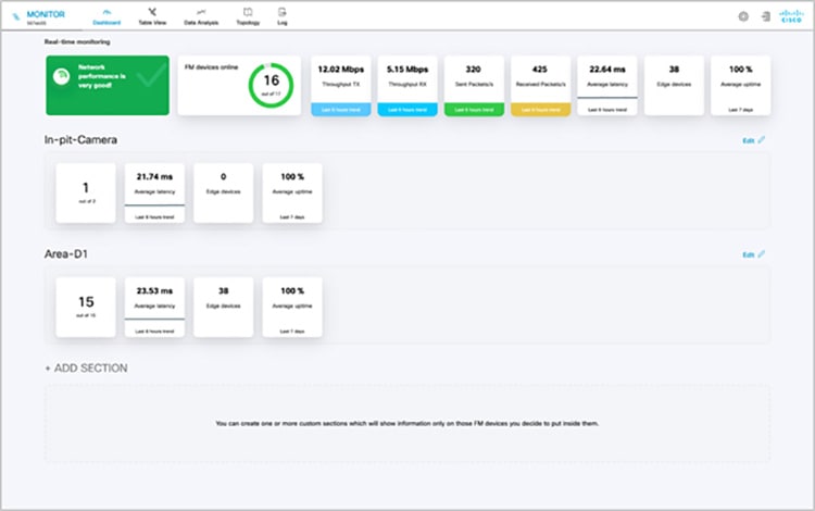
The dashboard shows overall network performance and offers customizable segmentation of the network into clusters. This allows for easy monitoring of network sections or parts of a fleet of vehicles, maximizing network usage and performance. Clusters can include backhaul point-to-point links, point-to-multipoint distribution networks, vehicle access networks, wayside networks, and vehicle-mounted radios. FM Monitor displays and tracks real-time Key Performance Indicators (KPIs) within each cluster, including the number of active radios, number of connected IP edge devices, end-to-end latency, jitter, upload/download throughput in real time, and system uptime.
Figure 19 FM-MONITOR Dashboard
FM-Monitor Table View
The table view allows customers to condense sections of the network into a tabular view, isolating specific radio configurations and performance statistics. During troubleshooting, this drastically reduces the time needed to understand system performance on a radio-by-radio basis.
Figure 20 FM-Monitor Table View
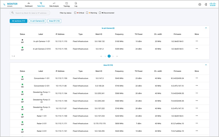
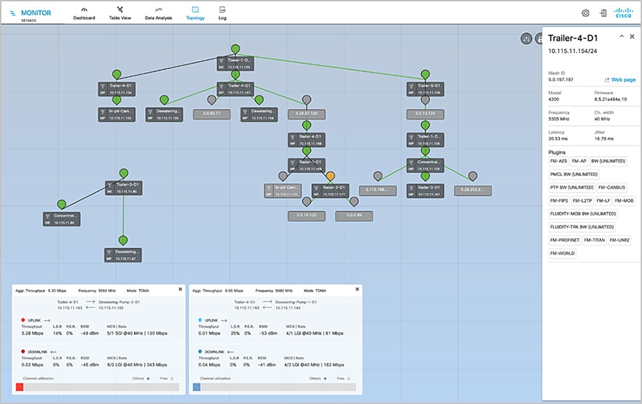
Figure 21 FM-Monitor Topology View
CURWB - Terminology and miscellaneous configurations
The following section covers some prerequisites to understand the CURWB architecture and deployment.
Mesh-ID
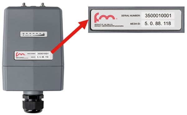
The Mesh-ID is a hardware identifier for the CURWB Gateways and Radios. It is pre-programmed from the factory with a hard-coded value which cannot be modified. It follows the Format of 5.x.x.x. Note that this is NOT an IP Address. The Mesh-ID is relevant within the constructs of network design. A gateway/radio with lower Mesh-ID becomes the “primary”. Also the gateway/radio with the lowest Mesh-ID becomes the Mesh-End (if one is not explicitly configured).
Passphrases

CURWB gateways/radios are configured with shared passphrases. CURWB control plane traffic is encrypted using this passphrase. The passphrase can also be used as a means to segment a particular network in that radios with the same shared passphrase form a cluster and are kept separate from other mesh networks which use a different passphrase.
Note: Data-plane / user traffic is not encrypted using the passphrase. In order to encrypt data-plan / user traffic, AES encryption must be enabled on the gateways/radios.
Note: If a shared passphrase is defined, the same passphrase must be used for all Fluidmesh units in the same network. As a deployment best-practice configure the passphrase to be something other than the default value of “Fluidmesh”. The shared passphrase can be composed of any ASCII characters except the following special characters: '(single quote),`(apostrophe), "(double quote), \(backslash), $(dollar sign), or =(equal sign).
MTU Considerations
■![]() Similar considerations as for normal MPLS
Similar considerations as for normal MPLS
■![]() Minimum required MTU on switches = 1544
Minimum required MTU on switches = 1544
■![]() Radios don’t have to be configured with MTU – this is done automatically
Radios don’t have to be configured with MTU – this is done automatically
Spanning Tree Protocol (STP)
STP is a Layer 2 protocol that runs on switches to prevent loops in the network when there are redundant paths in the network. Switches run the STP algorithm when they are first connected to a network or whenever there is a topology change. CURWB radios do not participate in the STP alongside the switches. The radios simply forward or block the BPDU messaged depending on how they are configured. CURWB radios have an equivalent process to STP, called AutoTap, and this helps avoid any loops within the wireless network.
BPDU Snooping can be enabled or disabled on the radio, according to the configuration the radio will act or not act on the contents of the BPDU.
BPDU forwarding, configured as ‘Pass’, forwards all the BPDUs. BPDU forwarding, configured as ‘Auto’, forwards the BPDUs in the wayside space and not forward them to the vehicle space and vice-versa. When BPDU forwarding is configured as ‘Stop’, no BPDUs are forwarded.
AutoTap
AutoTap is a network loop prevention mechanism that allows CURWB radios to detect connections and allow only a dedicated ingress/egress route to and from the Mesh End or network core.
With AutoTap, only one radio will publish MAC address information, and traffic is seen coming from only one radio that gets elected as the Primary radio of the physically connected redundant group. The radio with the lowest Mesh ID is selected as the Primary radio which advertises its MAC address. With this configuration, the radios are able to detect each other over the wired connection, and forward traffic to the connected radio utilizing this connection. Routes to the core and end devices are built automatically. The result is like having a single radio with multiple wireless interfaces.
Network Time Protocol (NTP)
As a best-practice, NTP should be configured on the CURWB radios. A primary and secondary NTP server IP can be configured during RACER template configuration. When enabling NTP on the radio, it will synchronize time from the NTP server usually within an hour, however we can force it to happen sooner, the connection will be down for milli-seconds when forcing the radio to connect to the NTP server.
CURWB Radio Behavior
Below describes the typical behavior of a CURWB radio:
■![]() Populate local VBR (Virtual Bridge Routing) table with local end points
Populate local VBR (Virtual Bridge Routing) table with local end points
■![]() Over each antenna (with configured channel/frequency): Find peer radios
Over each antenna (with configured channel/frequency): Find peer radios
–![]() Condition: Same passphrase, same cluster-id
Condition: Same passphrase, same cluster-id
–![]() Find peer radios and gateways
Find peer radios and gateways
–![]() Pseudowire-set: “Mesh-End only”: To Mesh End only
Pseudowire-set: “Mesh-End only”: To Mesh End only
–![]() Pseudowire-set: “All”: To all other radios
Pseudowire-set: “All”: To all other radios
–![]() Radio metrics determine path: Higher signal strength wins over alternative path (over full path)
Radio metrics determine path: Higher signal strength wins over alternative path (over full path)
■![]() Used for Loop Avoidance when two radios using the same passphrase are directly connected using the wired network
Used for Loop Avoidance when two radios using the same passphrase are directly connected using the wired network
■![]() Directly connected radios select a primary; radio with lower mesh-id becomes primary; only primary announces local endpoints either connected via switch or directly to a radio
Directly connected radios select a primary; radio with lower mesh-id becomes primary; only primary announces local endpoints either connected via switch or directly to a radio
■![]() The AutoTAP feature kicks in automatically and no configuration is needed
The AutoTAP feature kicks in automatically and no configuration is needed
■![]() For each LSP: announce local VBR table, Learn remote VBR table entries
For each LSP: announce local VBR table, Learn remote VBR table entries
Note: AutoTAP is independent of LSPs. It does not influence LSPs or block ports (like STP does).
Note: The maximum throughput of a radio includes both directions, upstream and downstream. E.g., a 150M radio cannot support 100M upstream and 100M downstream traffic.
VLAN Design

On CURWB radios, VLAN support is not enabled by default and can be enabled by installing an optional plug-in. Installing and enabling the VLAN plug-in is recommended to control how tagged and untagged traffic is propagated through the network. When enabled, two VLANs are configurable, one for management of the radio unit and the other one is the CURWB Native VLAN. The CURWB management VLAN is used for control plane communication between the radios and also to connect, configure and manage the CURWB devices. The native VLAN determines how untagged traffic will be handled as it passes through the radio. Setting the native VLAN to 0 is a special case where all untagged traffic is dropped and only tagged traffic can pass through the radio unit.
The switch interface connected to a CURWB radio should be configured as a trunk port on the CURWB management VLAN and the client traffic VLAN(s). Note that the CURWB radio has some limitations on VLAN tagging. It is highly recommended that VLAN tagging be done on the directly-connected switch.
CURWB Fixed Infrastructure – Wireless Backhaul
The CURWB Fixed Infrastructure architecture consists of two different deployment models:
CURWB PtP in Mesh Mode
Figure 25 CURWB Wireless Backhaul – PtP in Mesh Mode
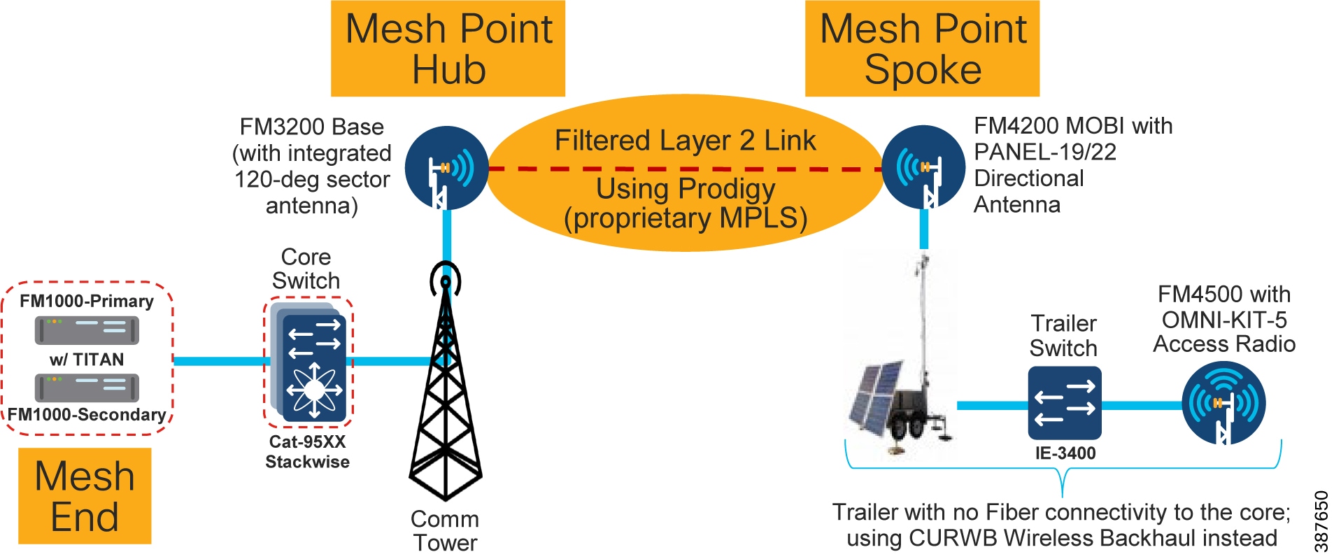
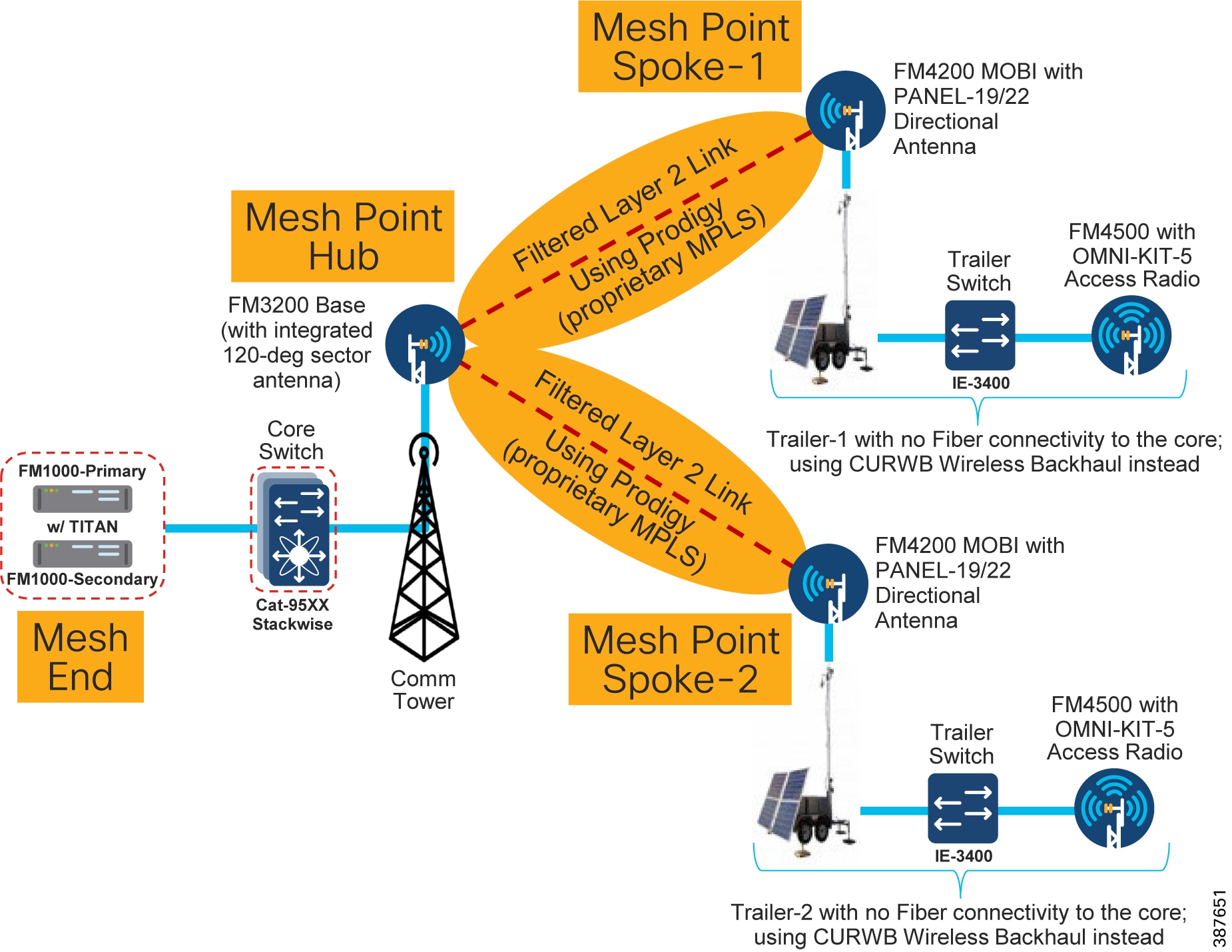
The CURWB PtP wireless backhaul can be used for individual trailers not having any fiber connectivity to backhaul traffic to the core. The PtP in Mesh Mode acts as a filtered L2 link in which not all protocols are enabled by default (e.g., IP multicast traffic). It leverages the proprietary Prodigy MPLS technology. The radio closer to the core is configured as a Mesh Point Hub and the radio on the trailer is configured as a Mesh Point Spoke for the PtP link. All the IP addresses need to be on the same subnet. The radio IP addresses are used for configuration and management of the radios.
Note: There is also a PtP Bridge mode deployment, which does not use the MPLS overlay, available for CURWB backhaul, however this is not recommended within a Mining deployment. The PtP in Mesh mode is the preferred deployment model since it enables flexibility to convert it to a PtMP link in the future to provide flexibility for the scenario in which trailers need to be moved around the mine pit.
Note: For PtP in Mesh Mode, not all protocols are enabled by default. These need to be enabled (e.g. IP Multicast, PROFINET, etc.). Multicast is a built-in feature whereas PROFINET requires a separate plug-in to be installed on the CURWB radio units.
CURWB Mesh End
A logical Mesh End (ME) can be redundant consisting of two physical Mesh End gateways/radios with the TITAN high-availability plug-in. The ME is typically configured within the Core network. The purpose of the Mesh End radio is to terminate all the MPLS label-switched paths and act as a gateway between the CURWB network and the wired network. The ME holds all the Label Switch Paths (LSPs) to all the other radios in its database.
Even though the CURWB solution has the capability to automatically select the gateway/radio with the lowest Mesh-ID to become the ME, as a best-practice it is highly recommended to configure the role of Mesh End and Mesh Point(s) manually within the deployment to have more deterministic convergence in case of failure within the network.
Note: In mining deployments where a CURWB Fixed Infrastructure is deployed alongside the CURWB Fluidity mobility, the CURWB L2 Fluidity gateway(s) within the core network are configured as the Mesh End. The PtP or PtMP hub radios are configured as MPs.
CURWB PtMP in Mesh Mode
A CURWB Point-to-Multi-Point (PtMP) deployment is used to connect multiple trailers without fiber connectivity to a central hub. All the IP addresses need to be within the same subnet. When using Static configuration, all the radios are configured with the same radio settings (Frequency, Channel Width and Passphrase).
Figure 26 CURWB Wireless Backhaul – PtMP in Mesh Mode
Note: When deploying a PtMP configuration, ensure that the right bandwidth plug-in is applied at the central location aggregating the fixed wireless traffic in-coming from its wireless connected trailers. For example, if each of the trailers has a bandwidth plug-in for 10 Mbps throughput and traffic from three trailers is getting aggregated at the hub, ensure that the hub radio(s) have a minimum bandwidth plug-in for 30 Mbps throughput.
Design Considerations for CURWB PtP and PtMP Wireless Backhaul
It is recommended to deploy the FM3200 BASE radio unit for the PtP or PtMP hub since it comes with an integrated 120-degree sector antenna. This is convenient since it can provide 120-degree coverage around a Communications Tower to multiple trailers.
If the communications tower is located in the middle of a site that needs RF coverage all around, 3 FM3200 BASE radios can be deployed on the communications tower to provide 360-degrees of coverage.
The FM4200 MOBI radios are recommended to be installed on the trailers as the backhaul radio. These radios can be paired with either the FM-PANEL-19 or FM-PANEL-22 directional antennas pointing toward the FM3200 BASE sector antenna.
The reason the FM3200/FM4200 radios are recommended for either PtP or PtMP is because these models support the TDMA mode of transmission. The TDMA mode is not the default mode and can be configured by enabling the FLUIDMAX feature on the radios.
The FM3200/FM4200F radios can provide a total maximum throughput of up to 150 Mbps for each PtP or PtMP deployment.
For PtP or PtMP backhauls that need higher than 150 Mbps throughput, the FM3500 (Hub) /FM4500 (Trailer Backhaul) radios can be used which can provide throughput of up to 500 Mbps. However an important point to keep in mind when using these especially within a PtMP setup is that these radio models do not support the TDMA mode of transmission. Hence it is recommended to enable RTS/CTS when using this combination of radios. This has a slight drawback in that enabling RTS/CTS can cause a reduction in overall throughput and also the efficiency of the wireless medium decreases as the number of trailers associated with a single hub goes up, hence does not scale up very well. Due to this it is recommended to deploy the FM3200/FM4200F pair for PtMP deployments.
The PtP deployment can also be configured to use bridge mode instead of the mesh mode. The bridge mode provides the advantage of a simpler configuration and also the fact that it can transfer any kind of traffic across the wireless link. The PtP deployment in bridge mode is useful where-in traffic needs to be backhauled from the distribution to the core network for conditions where a fiber link cannot be deployed. PtP in bridge mode is not recommended to be used within the distribution layer even if initially there is a need to provide connectivity to just a single trailer. As mentioned previously a mine environment is pretty dynamic with mobile trailers needing to move. A PtP deployment configured for bridge mode will not be able to accept another trailer if the need arises in the future. Converting a PtP deployment from bridge mode to mesh mode will take time since they both use different set of plug-in licenses. Hence for the distribution layer it is highly recommended to deploy PtP links using the mesh mode to provide flexibility for addition of trailers to convert the PtP deployment into a PtMP deployment.
Note: In order to avoid RF interference and high channel utilization, it is mandatory to select a different non-overlapping RF channel for each of the wireless backhaul link (unless they are really far apart and cannot interfere with each other). Also, the RF channel(s) used for the fixed infrastructure should be different compared to the RF channel used within the access layer.
Note: When wireless backhaul is used for a trailer which does not have a switch, the access radio and the backhaul radio can be connected back to back using the LAN2 ports. If using POE injectors to power-up the radios, the LAN1 port on the POE injectors can be used to connect the two radios to each other. On the CURWB radios both LAN1 and LAN2 ports are bridged together so the radios can be connected back to back using any of the ports.
CURWB Fixed Infrastructure - Wireless Backhaul for Mine Deployments
When fiber is not available at a Trailer for the access radio, CURWB radios can be deployed in the fixed infrastructure mode to provide wireless backhaul connectivity to the core wired network. In this configuration, it is recommended that a backhaul radio be installed at a Trailer with fiber connectivity and the wirelessly connected Trailer be no more than 1 radio hop away.
When deployed alongside L2 Fluidity, the radios should be configured as mesh points with the same passphrase as the mesh end deployed for Fluidity. Bridge mode can also be used if a small number of Trailers need a wireless backhaul connection. Bridge mode is a variation of point to point in that the radios do not use MPLS encapsulation and cannot be expanded into a multipoint configuration. Because of this limited flexibility, mesh point is the preferred method over bridge mode. It is important to remember to use different frequencies for the fixed infrastructure radios which do not overlap with the access radios. Examples of both a point-to-point and a point-to-multipoint deployment are depicted below.
Note: Radios configured in Bridge mode don’t need to use the same passphrase as the Fluidity network. A different passphrase needs to be used for each PtP bridge link.
Figure 27 Example of PtP and PtMP Wireless Backhaul within a Mining Deployment
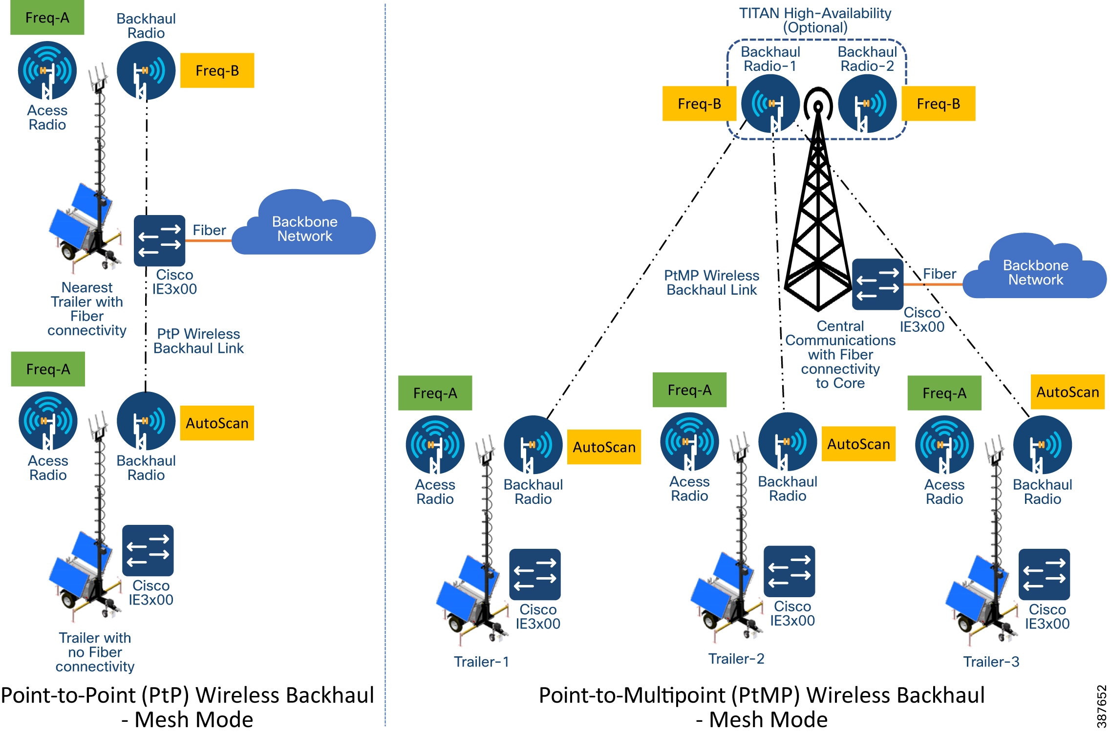
Note: In order to avoid RF interference and high channel utilization, it is mandatory to select a different non-overlapping RF channel for each of the wireless backhaul link (unless they are really far apart and cannot interfere with each other). Also, the RF channel(s) used for the fixed infrastructure should be different compared to the RF channel used within the access layer.
As a best-practice, the Trailer backhaul radios should be configured for AutoScan to enable mobility of trailers between different communications towers configured for different frequencies. All the communications tower radios need to be configured with the same passphrase to enable trailer mobility across different communications towers.
Because most mine autonomous operations need to operate 24x7 it is highly recommended to install a pair of CURWB FM3200 on the Communications towers especially for PtMP Hub deployments to provide high-availability protecting against hardware failure, since traffic from multiple trailers and autonomous vehicles will be aggregated and forwarded to the core
Tower-ID Feature
Figure 28 Behavior with Tower-ID feature disabled
The ‘Advanced Radio Settings’ section also contains the Tower-ID parameter.
This feature is used only on Hub Radios. As seen in the figure above, the network uses two radio towers with four Hub Radios each. Each hub radio operates on a different channel, but has the same cluster id and passphrase. The two towers are also linked by a Fiber optic backbone network.
Now, consider radio 5.0.0.10 on tower 1, and radio 5.0.0.20 on Tower 2. Both radios use the same channel, passphrase and cluster id, but Tower ID values have not been configured for either radio. Since they are both linked by radio and fiber optics, the radio with the numerically lower Mesh ID, in this case 5.0.0.10, will automatically become the primary radio. 5.0.0.20 will also stop advertising itself to any other radios, as it is considered to be a backup or secondary radio.
The trailer-mounted Spoke radio is connected to Hub radio 5.0.0.10. If this radio is moved to a location where it receives a stronger signal from radio 5.0.0.20, it will not be able to switch Hubs, because 5.0.0.20 is identified as a backup radio. This will cause unwanted radio behavior, and gaps in coverage.
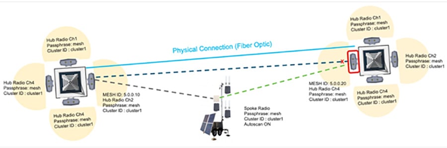
Figure 29 Behavior with Tower-ID feature enabled

Leveraging the Tower-ID feature helps solve this coverage gap issue. Hub radios 5.0.0.10 and 5.0.0.20 are both assigned the same passphrase, cluster ID and operating frequency, but each radio is assigned a different tower ID. This allows both radios to identify themselves as Primary radios within the same cluster.
The trailer-mounted Spoke radio is connected to Hub radio 5.0.0.10. Now, if the trailer is moved to a location where it receives a stronger signal from radio 5.0.0.20, it will automatically switch Hubs, because radios 5.0.0.10 and 5.0.0.20 are both identified as Primary Hub radios. Leveraging the Tower-ID feature, a larger area can receive radio coverage.
CURWB Mobility Architecture – Layer 2 Fluidity
The figure below depicts a typical L2 Fluidity mobility architecture for mining. A pre-requisite for L2 Fluidity is that all the CURWB devices (mesh-end gateways, access radios, and mobile radios) need to be within the same VLAN/IP subnet/L2 broadcast domain and configured with the same passphrase.
The core layer consists of a redundant pair of mesh-end gateways. The role of the mesh-ends is to terminate the MPLS tunnels from each of the vehicle and access radios and act as a demarcation point between the wired and the wireless domains. The mesh-ends are responsible for de-encapsulating the MPLS header and then forwarding the traffic to the distribution/core switch. For the traffic originating from the wired network and going towards the mobility domain, the mesh-ends act as the default gateway and are also responsible for the MPLS encapsulation and forwarding the traffic to the appropriate vehicle radio.
Figure 30 CURWB L2 Fluidity + CURWB Wireless Backhaul Architecture for Mining Autonomous Vehicles (Single Frequency)
The access radios are configured as mesh points in the L2 Fluidity mode with same passphrase that is configured on the mesh-ends. The role of the access radios is to provide RF coverage for the mobility domain. The access radios are distributed across the area where wireless coverage is required while the vehicles roam. In the above architecture all the access radios are configured to operate in the same frequency.
The radio on the vehicles are configured in “Vehicle” mode and are statically configured to use the same frequency used on the infrastructure radios.
The network architecture is based on Prodigy 2.0, MPLS-based technology, which is used to deliver IP-encapsulated data. MPLS provides an end-to-end packet delivery service operating between levels 2 and 3 of the OSI network stack. It relies on label identifiers, rather than the network destination address as in traditional IP routing, to determine the sequence of nodes to be traversed to reach the end of the path.
An MPLS-enabled device is also called a Label Switched Router (LSR). A sequence of LSR nodes configured to deliver packets from the ingress to the egress using label switching is denoted as a Label Switched Path (LSP), or “tunnel”. LSRs situated on the border of an MPLS-enabled network and / or other traditional IP-based devices are also called a Label Edge Router (LER). The ingress node of the path classifies incoming packet according to a set of Forwarding Equivalence Classes (FEC); when a packet matches a class, it is marked with the label associated with the particular class and then forwarded to the next node of the sequence, according to the information configured into the Forwarding Information BAse (FIB) table of the node. Subsequently, each intermediate node manipulates the MPLS label(s) stored into the packet and then it forwards the data to the next node. The egress node finally removes the label and handles the packet using normal IP routing functions.
The FIBs on the different nodes of the network are managed by means of a Label Distribution Protocol (LDP) that is the primary component of the so-called network control plane. Fluidity relies on a custom label distribution protocol that provides automated installation of LSPs among the different nodes of the network; this ensures that each node can be reached from any other node.
In traditional MPLS networks, whenever the network topology changes for any reason, the FIBs of the nodes involved must be reconfigured to adapt to the new paths. This is usually performed using the standard label distribution protocol signaling available.
In a mobility network scenario, the handoff process can be assimilated to a network topology change, where a link is broken and a new one is created like in Wi-Fi. The standard mechanisms to detect the change and reconfigure the nodes are, however, too slow and data-intensive to provide adequate performance in a real-time constrained scenario such as high-speed mobility. In particular, the whole reconfiguration latency and the number of messages exchanged should be minimized to reduce the chances that some data packets are lost in the process.
To mitigate the mentioned issues, Fluidity implements a fast handoff solution that is able to provide very fast path reconfiguration with latency in the order of one millisecond. The considered mechanism is proposed as an extension to the existing control plane of the network and it is based on a specific manipulation technique concerning the MPLS FIB tables of the nodes.
The scheme proposed allows mobile nodes, and client devices attached to them, to maintain their IP address throughout the mobility process. Besides, all nodes are part of a single layer-2 mesh network. The layer-3 handoff process is seamless in the sense that, thanks to a make-before-break strategy, the availability of at least one valid LSP is ensured during the handoff transitory as the network is reconfigured.
LSPs connecting to the static backbone are installed and updated whenever the vehicle performs the handoff procedure using dedicated signaling. LSPs are always present as long as a mobile radio is communicating with a fixed infrastructure radio. Labels change as it roams, but the LSPs are always present.
L2 Fluidity Packet Flow
Figure 31 L2 Fluidity Packet Flow
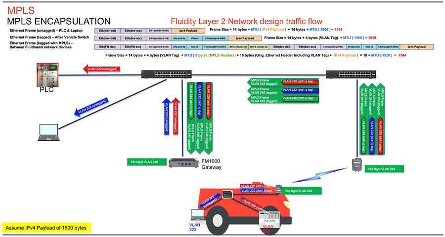
The figure above depicts the L2 Fluidity packet flow from the vehicle to the control room. The laptop on the vehicle is configured to be in Access VLAN 222 and the PLC is configured to be in Access VLAN 220. The packets from the laptop and PLC on board the vehicle are untagged when they enter the on board switch. Assuming an IPv4 payload of 1500 bytes, the untagged ethernet frame size is 1514 bytes. The switch on board the vehicle adds the appropriate IEEE 802.1q VLAN tag to each of the packets. After the IEEE 802.1q VLAN tag of 4-bytes is added, the frame size is now 1518 bytes. The IEEE 802.1q tagged packets are then forwarded to the CURWB radio on board the vehicle.
The CURWB radio on board the vehicle then takes those packets and imposes and MPLS label, tags them with the CURWB Mgmt VLAN IEEE 802.1q tag (VLAN-248) and forward them to the wayside infrastructure CURWB radio to where the vehicle radio is currently connected. Along with the MPLS header of 8-bytes an additional IEEE 802.1q VLAN tag of 4 bytes and an ethernet frame of 14-bytes the frame size now becomes 1544 bytes. The MPLS encapsulated frames with an IEEE 802.1q tag of VLAN-248 are forwarded to the CURWB FM1000 gateway.
The CURWB FM1000 gateway de-encapsulates the MPLS header and forwards the original IEEE 802.1q tagged frames onward to the control room switch. The control room switch removes the 802.1q header and forwards the frames towards their intended destination.
Fluidity Rate Adaptation
The Fluidity rate adaptation setting controls the unit choice of modulation coding and speed of packet transmission. Fluidity supports two different rate adaptation modes:
■![]() Standard: This option applies a standard re-active rate selection as used by Wi-Fi access points
Standard: This option applies a standard re-active rate selection as used by Wi-Fi access points
■![]() Advanced: This option applies CURWB proprietary predictive rate selection algorithm
Advanced: This option applies CURWB proprietary predictive rate selection algorithm
For the mining autonomous vehicle use-case it is recommended to leverage the Advanced rate adaptation. The CURWB predictive rate selection algorithm is pro-active. In a congested environment LER is kept low by predictively adjusting the data rate and this helps to prevent packet loss. The predictive algorithm tries to keep the LER and packet loss low by selecting a more conservative data rate. As opposed to this, the standard rate selection algorithm would need higher LER and packet drops to adjust to a lower data rate. Rate selection is also important to obtain good performance and to maximize the throughput of the radio communication system.
The RSSI prediction is performed by the transmitting radio using explicit feedback received from the destination radios. This results in a good estimate of the upstream channel condition. For further accuracy the system also filters out all instantaneous variation that may have a detrimental impact on the choice of the transmission rate.
The transmission rate is then selected according to the prediction of the estimated drawing from a small set of optimal rates computed by a heuristic channel estimation algorithm. Within high-speed mobility environments, the channel state changes very quickly. Therefore, it is important that the rate sampling algorithm finds the optimal rates in the shortest time possible while keeping accuracy. Failure to meet either condition typically results in low throughput, high latency, and high packet error rate (PER).
When the rate adaptation is set to Advanced, the vehicle radio bases the selection of MCS based on the RSSI received from the wayside infrastructure radio. The RSSI scale is divided into a number of non-overlapping bins, each bin corresponding to a subset of MCS values to be sampled by the rate selection algorithm. The RSSI bin definitions and their associated MCS subsets can be determined according to several criteria, which may include, for example, the sensitivity thresholds of the underlying wireless hardware. The table below shows the default values for the RSSI bins and the corresponding MCS rate selected.
Fluidity Handoff Logic
Within standard Wi-Fi based communication, a handoff is triggered by the Wi-Fi client based on pre-configured static thresholds like RSSI and/or SNR. For example a Wi-Fi client might be configured to trigger a handoff when its RSSI value drops below -75 dBm. CURWB on the other hand uses a dynamic handoff decision algorithm.
As can be seen in the figure below, the vehicle radio always operates on the top line (RSSI Envelope), handing over from the currently connected radio to the next available radio as soon as the difference in RSSI meets the configured hysteresis threshold.
Figure 32 Fluidity Dynamic Handoff Decision
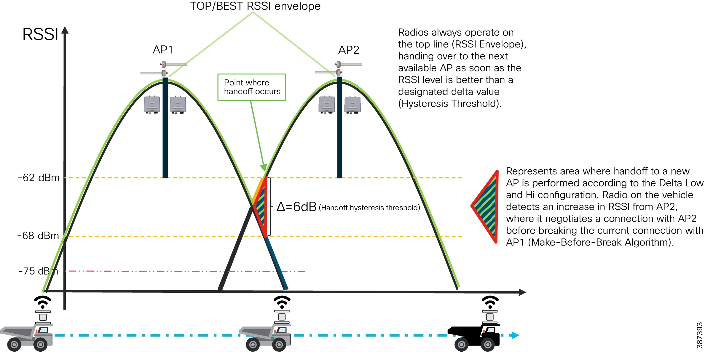
Figure 33 Fluidity Predictive Rate Selection and Handoff Location
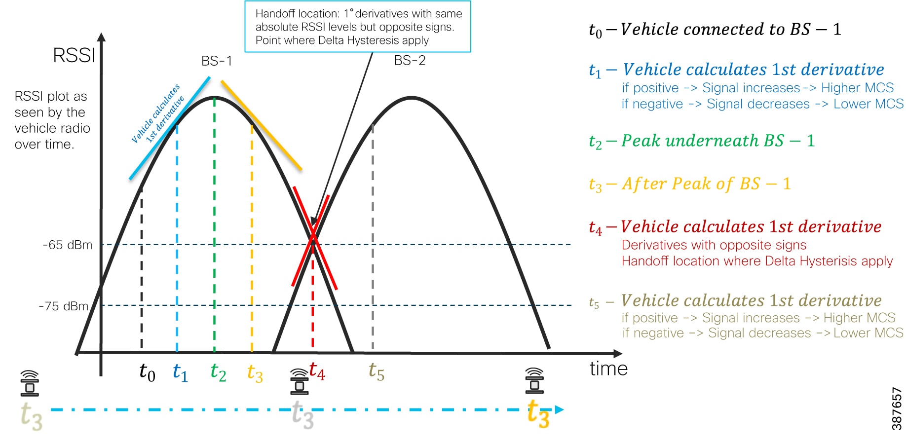
Fluidity Advanced Handoff Tuning for Vehicle Radio Units
The CURWB solution provides certain advanced handoff parameters for vehicle radio units that can be tuned depending on the RF environment to achieve optimal handoffs.
The RSSI zone threshold and Handoff hysteresis threshold features provide safeguards against unwanted handoffs – in other words, against unreasonably long periods of time between received signal strength from the connected unit falling too low, and a handoff request from a relief unit.
The relationship between these three settings governs whether a handoff will take place from one unit to another, based on a difference in comparative signal amplitude values over a period of time.
The RSSI low/high zone threshold sets the border between the low and high RSSI zones. In this case, as represented by the two graphs below, the -60 dB level marks the border between the low and high RSSI zones.
The threshold value is always expressed as SNR, with -95 dBm as the reference value, and is always expressed as a value greater than 0. The default value is 35. This equates to -60 dBm.
Figure 34 RACER Fluidity Advanced Handoff parameters

The default Fluidity delta-threshold is -60dBm. The default delta-high threshold is 6 dBm. What this means is that in good RF environments where the signal strength is higher than -60 dBm, the vehicle radio will only attempt a handoff to another wayside infrastructure radio if it provides a signal that is at least 6 dBm higher than what it is receiving from its currently connected wayside infrastructure radio. If the delta value is lower than 6, no handoff will occur at that time.
Figure 35 Fluidity delta-high example

The default delta-low threshold is 3 dBm. What this means is that in poor RF environments where the signal strength is lower than -60 dBm, the vehicle radio will attempt a handoff to another wayside infrastructure radio if it provides a signal that is at least 3 dBm higher than what it is receiving from its currently connected wayside infrastructure radio. If the delta value is lower than 3, no handoff will occur at that time.
Figure 36 Fluidity delta-low example
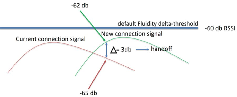
Note: The Fluidity delta-threshold, the delta-high and delta-low values are all configurable to values different from the default using either RACER or the radio CLI if needed for your RF environment tuning.
CURWB Fluidity Advanced - Large Network Optimization
Large network optimization (LNO) is useful in large network environments of more than 50 infrastructure radios where it helps optimize the MPLS forwarding table by only establishing LSPs toward the Mesh-End unit.
The Mesh-End is the ingress/egress point of the MPLS domain. Spanning Tree Protocol (STP) is also affected in that BPDU forwarding will be disabled.
If LNO is enabled, the Mesh points will only establish LSPs with other Mesh-End devices, and it also disables STP packet and BPDU forwarding.
If LNO is disabled, LSPs will be created between all Mesh-points, and between Mesh points and Mesh-ends. STP packets and BPDU forwarding will be set to Automatic.
For this deployment within an Open-Pit mine it is recommended to disable the LNO feature.
Note: LNO feature, if enabled will override the Pseudo-wires configuration within MPLS settings.
Load Balancing Handoff Mode (Optional)
An optional Load Balancing Handoff algorithm can be configured for certain use-cases or scenarios where-in we expect to see a higher than usual density of autonomous vehicles within a certain geographical area within a mine-pit. In this case, we can use the Load Balancing Handoff mode to load-balance the vehicles across multiple infrastructure radios that are installed within that geographic area. The condition for load balancing across the multiple infrastructure radios is that the radios must all provide pretty similar signal strength. If the RSSI provided by a certain infrastructure radio is below a defined threshold it will not be considered as a target for load balancing.
Degree of Preference (DoP)
DoP is an a dimensional metric computed by each unit (mobile and infrastructure) that represents its current load level. The metric is constantly updated every 5 seconds and when certain events occur in the network (handoffs, topology changes, etc). Higher values correspond to increased load levels, which make the unit less preferable for establishing a connection.
Each unit continuously advertises its DoP value to the rest of the world. Mobile units utilize the DoP received from Infrastructure radios to determine the “best” AP to connect to (load-balancing handoff). Infrastructure units utilize the DoP received from Mobile radios to independently perform admission control upon reception of handoff requests.
Selection of “best” Infrastructure unit
■![]() An Infrastructure unit is eligible for handoff by a Mobile unit if the mobile is already connected to it, or:
An Infrastructure unit is eligible for handoff by a Mobile unit if the mobile is already connected to it, or:
■![]() Its RSSI is above the critical threshold (scan-rssi-threshold)
Its RSSI is above the critical threshold (scan-rssi-threshold)
■![]() Its advertised DoP is lower than the configured DoP limit (dop-limit)
Its advertised DoP is lower than the configured DoP limit (dop-limit)
■![]() It’s not blacklisted, e.g. it did not reject a handoff request in the past 15 seconds and it’s not currently banned by the pole-ban algorithm
It’s not blacklisted, e.g. it did not reject a handoff request in the past 15 seconds and it’s not currently banned by the pole-ban algorithm
An Infrastructure unit R will accept a handoff request from a Mobile unit if a) the mobile is already connected (timeout: 5 minutes) to it, or R's current DoP is below the configured limit (dop-limit + dop-client) and b) the number of connected clients is smaller than the configured limit (max-clients).
A Mobile unit will constantly determine the best eligible Infrastructure unit operating on the current frequency on the basis of the collected RSSI and DoP values. In particular, the optimal unit is chosen as the one providing:
■![]() The strongest RSSI (within rssi-delta dBm from the strongest value received)
The strongest RSSI (within rssi-delta dBm from the strongest value received)
■![]() In case of multiple Infrastructure units operating on the same frequency and whose RSSI values differ for more than rssi-delta dBm, RSSI always takes priority over DoP in the selection of the best Infrastructure unit.
In case of multiple Infrastructure units operating on the same frequency and whose RSSI values differ for more than rssi-delta dBm, RSSI always takes priority over DoP in the selection of the best Infrastructure unit.
Vehicle Mobility Network
The vehicle mobility network comprises of vehicles installed with either a single or dual CURWB radios on-board. The CURWB FM4500 MOBI is the only model recommended to be used on board the vehicles since it is vibration resistant. Also it is mandatory to house the FM4500 MOBI radio within an FM-SHIELD enclosure. The on-board radios connect wirelessly to the Access Network radios and perform handoffs as the vehicle moves about the pit. The autonomous vehicles within mining typically will have at least 4 x cameras on board to enable autonomous and tele-remote operations. Apart from cameras the vehicles will most likely have Tire Pressure Monitoring (TPM) system, a vehicle control unit (VCU), etc.
Figure 37 Vehicle on-board High-Level Network Design
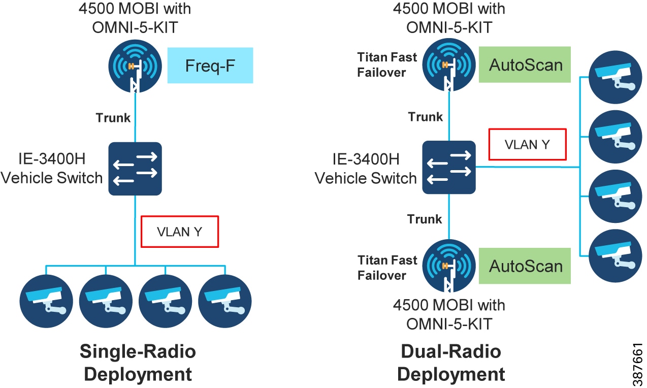
High-Availability (HA)
TITAN High-Availability Plug-in
For faster convergence it is highly recommended to install TITAN plug-in on all the radios in the deployment. The TITAN plug-in on the trailer radios helps speed-up Mesh-End check. However, since Mesh-End check only works with trailers that have wired connectivity we can skip installing the TITAN plug-in on trailer radios which have wireless backhaul connectivity.
Gratuitous ARP (GARP)
Enable GARP when enabling TITAN plug-in to advertise the secondary MAC address on failure of the primary unit.
Redundancy at the Core Layer
Figure 38 Redundancy and High-Availability at the Core Layer
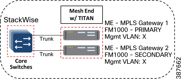
Catalyst-9500 StackWise Virtual High-Availability
Cisco StackWise Virtual is a two-node solution providing a Unified Control Plane Architecture by assigning one switch as active and the other as a hot-standby. Both the switches play an active role when it comes to data forwarding. Two Cat-9500 switches are connected together using a StackWise Virtual Link (SVL). The SVL helps bring the two switches together forming a single logical switch. Both the switches can be managed as a single entity. Since the control plane, management plane, and data plane are integrated, the system behaves as a single switch. The advantage of configuring the switches in a StackWise pair is that it provides hardware redundancy and fast failover.
FM1000 Mesh End Redundancy and TITAN Fast-Failover
It is highly recommended to purchase and apply the TITAN high-availability plug-ins for a pair of redundant FM-1000 Mesh Ends to be used within the mine deployment.
Once configured, TITAN is completely autonomous and ensures stable and reliable connectivity without the need for any human intervention. If data exchange ceases because of the failure of the primary mesh-end device, TITAN will detect the failure and re-route the traffic through the designated secondary device, re-establishing connectivity within a maximum of 500 mSec. When the failed primary mesh end device comes back online, the secondary mesh end device automatically reverts to its standby role.
It is highly recommended to power each of the FM1000 gateways using a different power source and connect them to different switches within the 9500 StackWise pair. This provides protection against power outages and switch hardware failure.
Primary election
All CURWB units connected to the same wired broadcast domain and configured with the same passphrase perform a distributed primary election process every few seconds. The primary unit constitutes an edge point of the Fluidmesh MPLS network, i.e. a device where the user traffic may enter or leave the mesh. Secondary units act as MPLS relay points.
For each neighbor, the algorithm computes a precedence value based on the role of unit (mesh-end or mesh-point) and its mesh-ID. Mesh-ends are assigned a higher priority than mesh-points and, among the same priority, the unit having the lowest mesh-ID is preferred. The election mechanism relies on a dedicated signaling protocol which constantly runs in the network and it guarantees that all units elect the same primary.
Mesh-end Failover
During normal operation, the primary and secondary mesh-ends constantly communicate to inform each other about their status and to exchange network reachability information. In particular, the primary periodically sends updates to the secondary regarding its internal forwarding table and multicast routes.
Primary Mesh-end Failure
When the primary mesh-end unit fails for any reason, a timeout expires on the secondary after not receiving keepalives for a configurable interval (typically between 50 - 200 mSec). At that point, the secondary becomes the new active mesh-end taking over the role of primary and it executes the following actions:
■![]() Issues a Primary Change command to inform all other units on the same wired network that the primary has changed. The message is propagated to mobile units as well using an efficient distribution protocol.
Issues a Primary Change command to inform all other units on the same wired network that the primary has changed. The message is propagated to mobile units as well using an efficient distribution protocol.
■![]() Updates the internal MAC and MPLS forwarding tables. This step is performed using a patented fast-rerouting technique that provides seamless performance.
Updates the internal MAC and MPLS forwarding tables. This step is performed using a patented fast-rerouting technique that provides seamless performance.
Sends gratuitous ARPs for the on-board devices on its ethernet/fiber port. This forces the network switch to update its MAC forwarding table (CAM) so that it will send traffic for on-board destinations through the port connected to the new primary.
When the other units receive the Primary Change command from the secondary, they perform the internal seamless fast-rerouting procedure (step 2), so that the traffic can be immediately forwarded with no additional delay and signaling required. This allows for fast network reconvergence, with an effective end-to-end service disruption below 500 mSec.
Primary Mesh-End Recovery
When the primary mesh-end is recovered, it initially scans the network for the presence of an active secondary mesh-end. If the detection is positive, then the unit enters an inhibition mode where-in the secondary remains the current edge point of the infrastructure for a certain amount of time (default 70 seconds). During this grace period, the primary receives updates from the currently active secondary mesh-end and acquires full knowledge about the state of the network. After that, it switches to being the primary node using the same procedure described above for failover.
CURWB Access Layer - Fast Convergence on Failure
Link Backhaul Check – Handoff Inhibition
Leveraging the Link Backhaul Check feature, an access radio unit detects a carrier loss on its Ethernet/Fiber port hence losing its ability to deliver mobility traffic to the mesh-end. The affected radio unit immediately advertises its status as ‘Unavailable’, by transmitting a ‘handoff inhibition’ message over the wireless channel. Upon receiving the ‘handoff inhibition’ message any existing mobile radios connected to this particular radio unit will try and search for another access radio to connect to. All mobile radio units currently connected to this unavailable access radio will find and connect to an alternative access radio unit within a few hundred milliseconds, typically within < 400 mSec. Also any handoff attempts from any other mobile radios to this affected access radio will be rejected. It is highly recommended to enable the Link Backhaul Check feature on the access radios within a mine deployment.
Figure 39 Link Backhaul Check – Handoff Inhibition
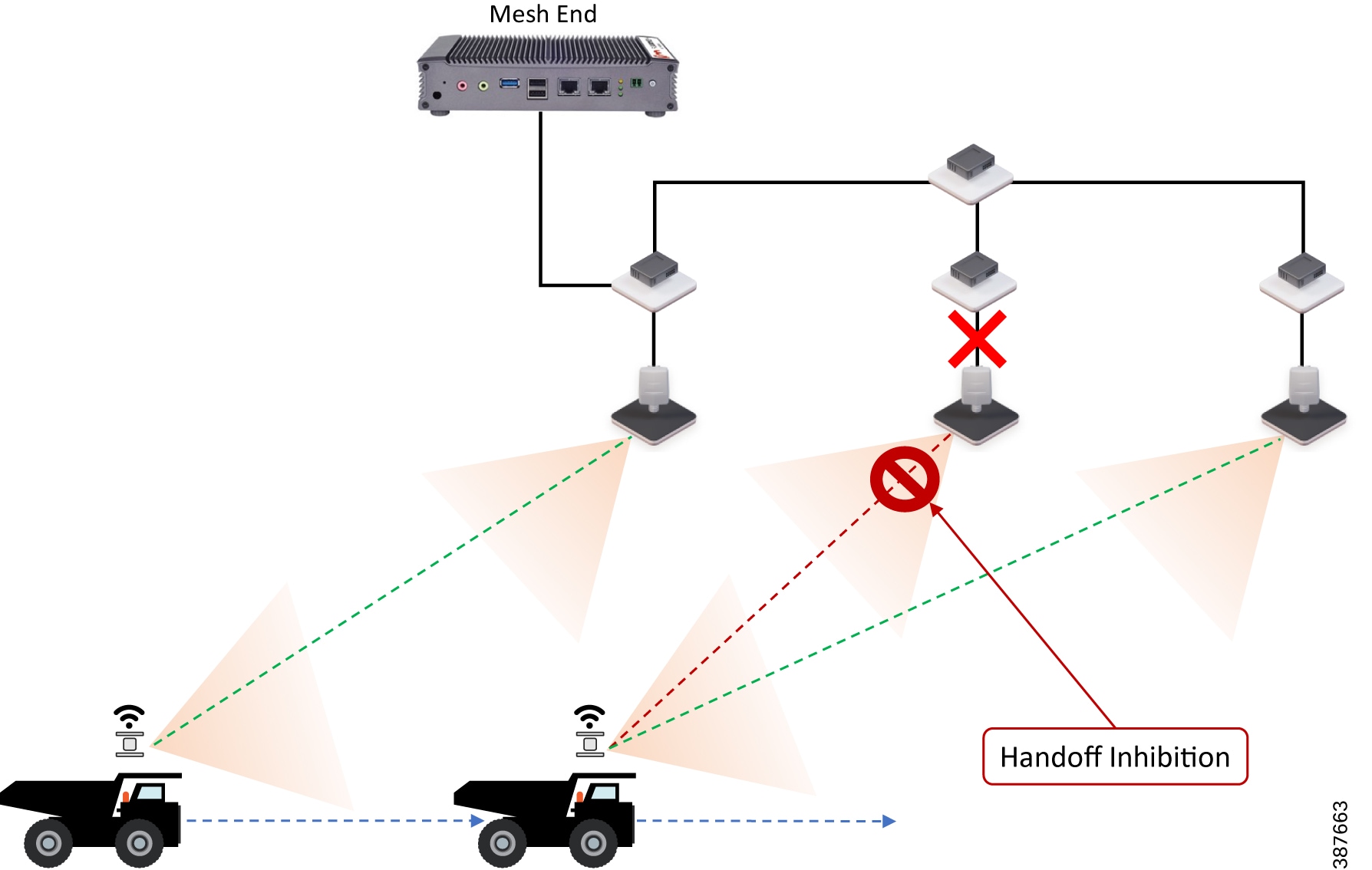
In the figure above it is shown that the link between the infrastructure radio and the Trailer/Pole switch is down. Assuming that the radio is not powered using PoE but via an external power source the radio is still up and providing good wireless connectivity to the vehicles. However since the wired link is down and the radio is not able to forward traffic to the wired network, the radio goes into handoff inhibition mode.
Mesh-End Backhaul Check – Handoff Inhibition
Using the Mesh-End Backhaul Check feature, an access radio unit may detect that it is not able to reach the active mesh end. This failure is triggered when L2 MAC reachability is lost to the active mesh end for 250 mSec. The affected radio unit immediately advertises its status as ‘Unavailable’, by transmitting a ‘handoff inhibition’ message over the wireless channel. Upon receiving the ‘handoff inhibition’ message any existing mobile radios connected to this particular radio unit will try to search for another access radio to with it can connect. All mobile radio units currently connected to this unavailable access radio will find and connect to an alternative access radio unit within a few hundred milliseconds, typically within < 400 mSec. Also any handoff attempts from any other mobile radios to this affected access radio will be rejected. It is highly recommended to enable the Mesh-End Backhaul Check feature on the access radios within a mine deployment that are installed on a pole with fiber connectivity.
Figure 40 Mesh-End Backhaul Check – Handoff Inhibition
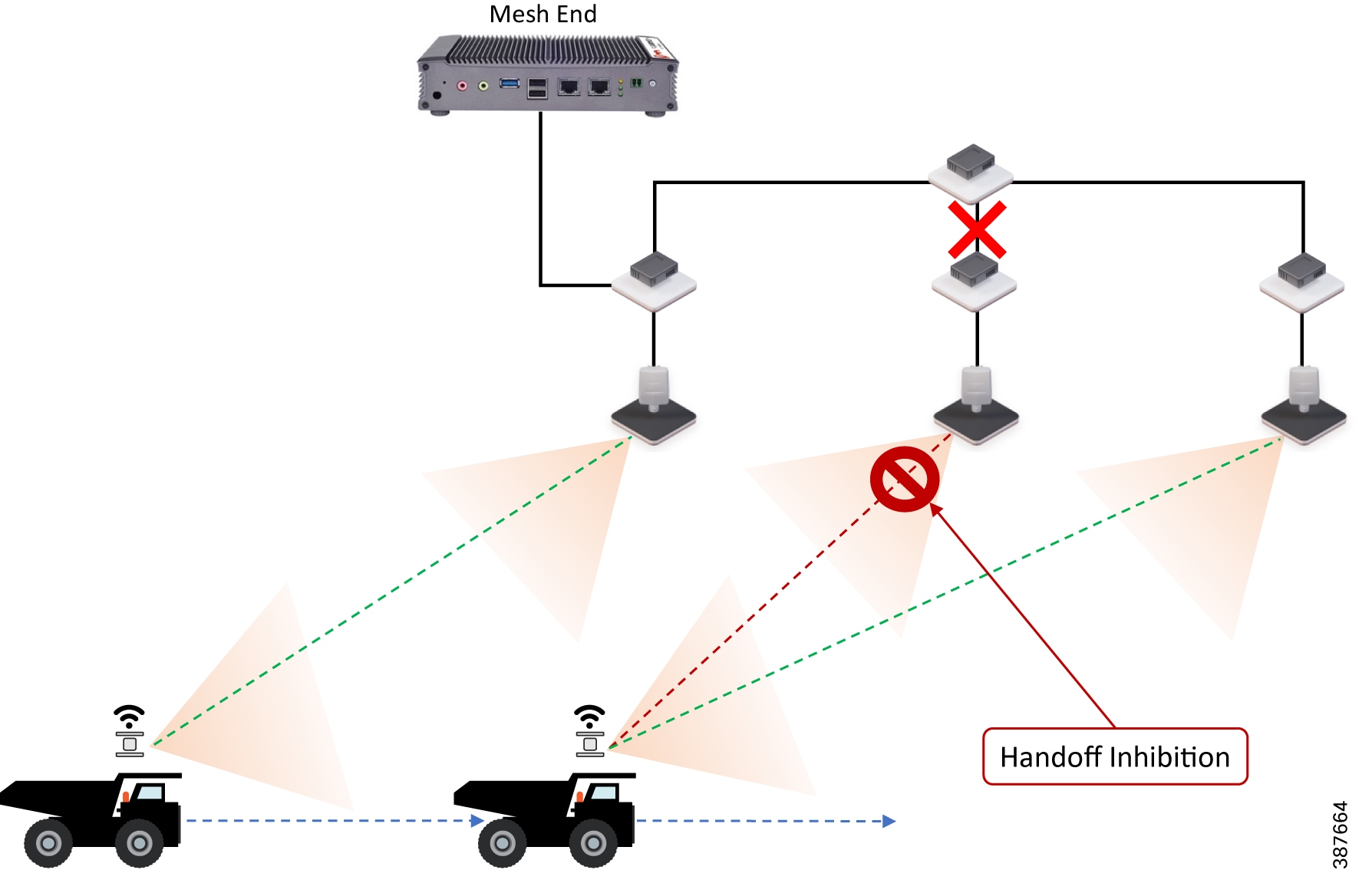
In the figure above it is shown that the Pole switch loses its fiber connectivity to the core switch, the infrastructure radio is powered on and providing good coverage and connectivity to vehicles but since the radio is not able to forward traffic to the mesh end located within the control room, it will go into handoff inhibition mode.
Note: The Mesh-End Backhaul Check feature is only supported for Wired (Ethernet or Fiber backbone) connected Mesh Points. Disable this feature when using wireless backhaul connectivity such as CURWB PtP or PtMP Wireless backhauls. Hence within a mine deployment this feature is recommended to be enabled on Pole Access radios and disabled on Trailer Access radios.
On-board Radio Redundancy - Failover and Recovery
TITAN high-availability is not just applicable for mesh ends. In scenarios where two CURWB radios are deployed on-board a vehicle, the two radios can paired-up together by applying the TITAN plug-in to provide hardware redundancy.
The on-board failover process is very similar to the mesh-end one and it encompasses the same steps described in the previous section by just swapping the infrastructure and the on-board networks.
■![]() The main difference is that when a mobile unit becomes the new primary after a failure or recovery event, it executes the following additional actions:
The main difference is that when a mobile unit becomes the new primary after a failure or recovery event, it executes the following additional actions:
–![]() If the automatic vehicle ID feature is enabled, it computes a new Vehicle ID and forces the update on all the on-board units accordingly.
If the automatic vehicle ID feature is enabled, it computes a new Vehicle ID and forces the update on all the on-board units accordingly.
–![]() It performs a forced handoff procedure instead of sending a ‘Primary change’ command to update the infrastructure network efficiently.
It performs a forced handoff procedure instead of sending a ‘Primary change’ command to update the infrastructure network efficiently.
QoS
CURWB implements DiffServ inspired QoS to provide end-to-end classification of user traffic. CURWB radios cannot perform any QoS marking. The radios only inspect the user traffic QoS marking and schedule based on those values. By default, during the MPLS encapsulation process the radios copy the DSCP value from the IP header or PCP value from the Ethernet header VLAN tag to the EXP bit within the MPLS header. For QoS purposes, CURWB radios don’t examine the IP header or the Ethernet header during the forwarding process. They examine the EXP bits within the MPLS header and give prioritization of one traffic type over another based on the assigned markings.
The CURWB default system setting is to preserve the original QoS priority marking unchanged. The QoS priority marking is then preserved through the whole end-to-end path to the egress switch. Priority scheduling is applied at the different transmission interfaces for each hop along the path. For packets being transmitted over the wireless link, the eight priority levels are further mapped into four access categories after scheduling. Each access category corresponds to a strict hardware priority scheduling order and a specific set of MAC transmission parameters which provide different levels of robustness and performance. Based on the QoS priority the packet is inserted in one of the four available hardware queues on the CURWB radio: Best Effort (BE), Background (BK), Video (VI) or Voice (VO).
Optionally, the CURWB radios can perform QoS remapping if needed to ensure that the packet is processed a certain way within the MPLS network. However, when leaving the MPLS network the packet will have its original QoS marking.
It is highly recommended that if the wireless network has been deployed to enable Autonomous and Tele-Remote applications, then only that application traffic should be transported over the CURWB wireless network. If there is a need to transfer other traffic over the CURWB wireless network, ensure that the Autonomous and Tele-Remote application traffic is marked with the highest priority so that it gets preference over all other traffic contending for the CURWB resources.
For vehicles that have a switch on board, the switch should perform the QoS classification and marking closest to the edge device and scheduling on the port facing the CURWB radio.
Cisco IE3x00 QoS
The Cisco IE3x00 switch supports Quality of Service (QoS) which allows a certain type of traffic to be treated differently at the expense of others, so the performance of high priority traffic such as TOS can be assured. Classification and marking are the first steps to implement QoS. Classification differentiates traffic type by examining the packet header. A packet can be classified based on the DSCP, the COS, and the IP precedence value in the header. It can also be classified with VLAN ID and Access control list (ACL).
Classification and marking is recommended at the entry point of the network. After the traffic is classified, certain QoS features can be applied in the policy map depending on the ingress or egress direction of the traffic. In the case of input policy applied to ingress traffic, the IE3x00 can be configured either to trust the marking from the client device or set it to a different value based on business requirements; for output policy that is applied to egress traffic, you can assign a percentage of bandwidth, shape transmission to certain rate, or set a queue-limit for specific traffic type. IE3x00 supports multiple queueing models such as class-based weighted fair queuing (CBWFQ), and priority queuing.
Security
All client traffic within the MPLS tunnel is already kept private using the system passphrase, however CURWB radios also support AES encryption which will apply to the MPLS tunnel traffic on the wireless links.
Note: To enable AES encryption feature, an AES plug-in needs to be installed on the radio. When configuring AES encryption, it is mandatory to enable AES encryption on all the radios within the system. Enabling AES only for a sub-section of the system is not supported and will cause a breakage.
Configuring CURWB to support Multicast Traffic
The Mining AHS use-case has a requirement to support both upstream (Vehicle to Control Room) and downstream (Control Room to Vehicles) multicast traffic. This section illustrates how to configure Multicast routing on CURWB network.
Figure 41 Multicast configuration on CURWB Mesh End Node
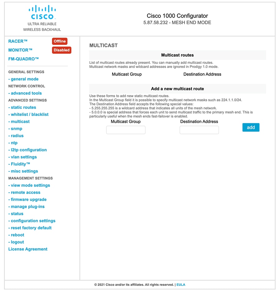
Multicast configuration within the CURWB network needs to be performed on the Mesh End node. The figure above illustrates how this can be accomplished using the FM1000 Mesh End Graphical User Interface (GUI). If TITAN Fast-Failover is enabled, both the Primary and Secondary Mesh Ends will need to have similar multicast configurations.
Let us assume our Multicast Group address for southbound (Control Room to Vehicle) traffic is 224.1.1.0/24 and the Multicast Group address for northbound (Vehicle to Control Room) traffic is 224.2.1.0/24.
For southbound multicast from the Control room towards the vehicles, the CURWB mesh end needs to send traffic to all the units that are part of the CURWB Mesh network. Hence the Multicast Group address needs to be configured as 224.1.1.0/24 and the Destination address needs to be specified as 5.255.255.255. This will prompt the CURWB mesh end to send any multicast traffic originating from the Control Room and destined to the vehicles to be sent to all the CURWB radios within the network.
For northbound multicast from the vehicles towards the Control room, each of the CURWB radios needs to forward the traffic to the CURWB Mesh End which ultimately offloads the traffic to the directly connected distribution/core switch to be delivered to the Control room. In this case the Multicast Group address needs to be configured as 224.2.1.0/24 and the Destination address needs to be configured as 5.0.0.0 which is a special address that will force each CURWB radio receiving any multicast traffic for the intended group to forward it to the Primary Mesh End. The destination address of 5.0.0.0 is able to accommodate any Mesh End fast-failover and fallback.
Table 6 CURWB Multicast Configuration Example
Multicast Traffic received my Mesh End is forwarded to all the CURWB radios within the Mesh Network. |
|||
Multicast Traffic received by any CURWB radios is forwarded to the Primary Mesh End node. |
Single-Frequency Architecture for Small Mine Deployments
Figure 42 CURWB Single-Frequency deployment – High-Level Network Architecture
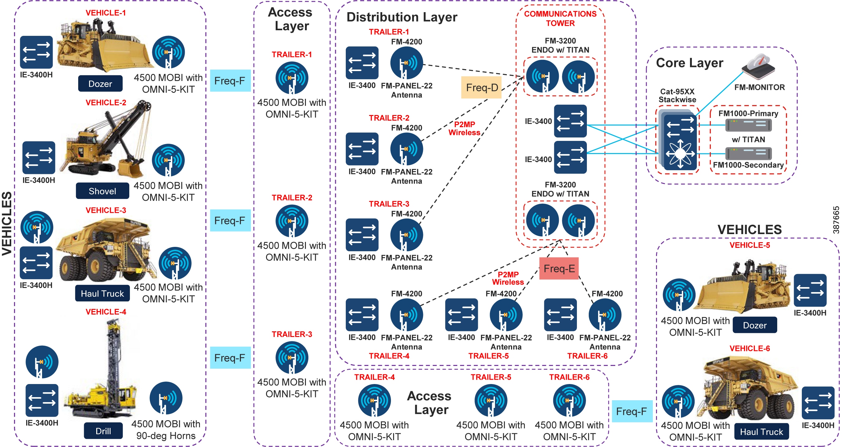
Figure 43 CURWB Single Frequency Deployment – Low-Level Network Architecture
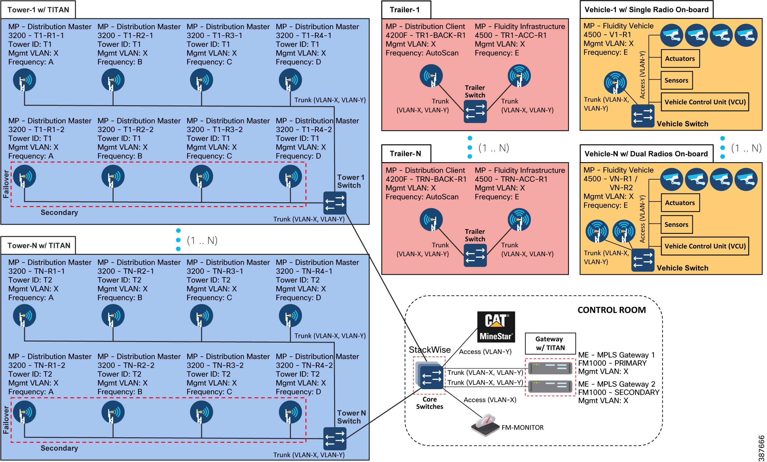
The figures above depict both the high-level and low-level architecture pertaining to a Single Frequency Access Layer deployment. Within the Core Layer there is a pair of redundant CURWB FM1000/FM10000 gateways connected to a pair of Cisco Catalyst 9500 switches configured as a StackWise high-availability pair. Note that each of the CURWB gateways is connected to a different switch within the StackWise pair to provide hardware redundancy in case of switch failure. Also deployed within the Core Layer is the FM-MONITOR on-prem monitoring solution used as a single pane of glass to monitor the entire CURWB deployment.
Trailers are deployed throughout the mine site wherever RF coverage is needed for autonomous vehicle operations. Trailers can either be connected using fiber to the distribution layer or in scenarios where fiber connectivity cannot be provided, CURWB wireless backhaul can be used to provide connectivity to the trailer. Trailers are deployed with the CURWB FM4500 MOBI radios to provide RF coverage to the autonomous vehicles. In order to provide wireless backhaul connectivity to the trailer a second radio is deployed on the trailer. The two radios need to be connected to each other using the trailer switch. In case of a single-frequency deployment the entire mine site is covered using a single 40-MHz wide channel. A different 40-MHz wide channel needs to be selected for each of the CURWB PtP or PtMP wireless backhaul networks.
The communications towers within the mine site are used to deploy the distribution layer of the network. The primary purpose of the communications tower is to aggregate traffic from multiple trailers. As mentioned previously, trailers can have connectivity to the distribution layer using either fiber or CURWB wireless backhaul. Within the CURWB wireless backhaul there are two deployment options available as discussed previously – Mesh PtP for single trailer connectivity or more commonly Mesh PtMP to provide connectivity to multiple trailers distributed across the mine site.
The typical deployment on the communications tower is the CURWB FM3200 BASE radio with an integrated 120-degree sector antenna to provide coverage to multiple trailer backhaul radios. This radio can either be deployed in standalone mode, providing no hardware redundancy or in cases where hardware redundancy is desired can be deployed as a high-availability pair with the TITAN high-availability plug-in installed on both the radios in the pair.
Either a single or multiple PtP or PtMP hub radios can be installed on a single communications tower depending on the topography of the mine and the distribution and location of trailers across the mine site. Also a mine site can have anywhere from one to multiple communications tower depending on the size and topography of the mine.
For trailer backhaul CURWB FM4200 radios are used along with FM-PANEL-19 or FM-PANEL-22 directional antennas forming either a PtP or PtMP CURWB backhaul with the communications tower.
A FM4500 MOBI radio is deployed on each of the vehicles. Each vehicle is also deployed with a switch on board.
For a L2 Fluidity deployment, all the CURWB radios need to be within the same VLAN/subnet. All the radios have a Management VLAN/subnet for management and configuration of the radio. All the radios within the deployment need to use the same passphrase. This passphrase is used to encrypt the CURWB control plane traffic within the CURWB network. If there is a need to secure and encrypt autonomous vehicle traffic over the CURWB network each CURWB radio within the deployment needs to have the AES plug-in installed and AES encryption enabled.
A separate VLAN/subnet needs to be dedicated for the devices within the mining AHS network located either on board the vehicle or applications within the control room. In order to enable VLAN functionality within the CURWB network, a VLAN plug-in needs to be applied to each of the CURWB radios within the network.
Multi-Frequency Architecture for Medium and Large Mine Deployments
Figure 44 CURWB Multi-Frequency deployment – High-Level Network Architecture
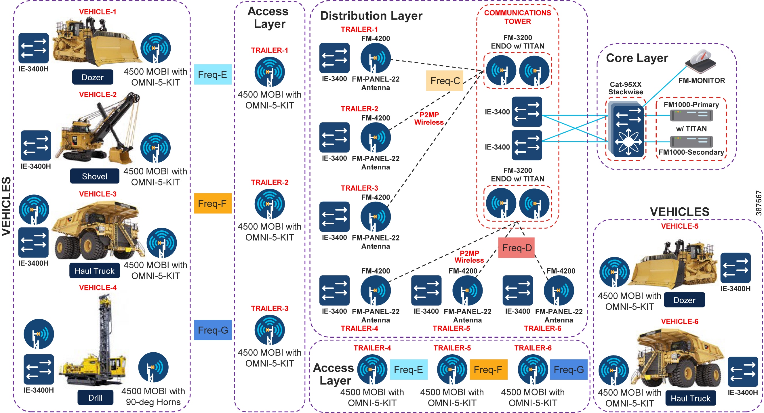
Figure 45 Multi-Frequency Architecture – Low-Level Network Design

The figures above depict both the high-level and low-level network architecture for a multi-frequency CURWB deployment for the mining autonomous vehicles application. The multi-frequency deployment is similar to the single-frequency deployment except that multiple 40-MHz wide channels are used at the access layer to provide RF coverage across large mines with high vehicle density. In order to provide seamless 0 mSec handoffs across the multi-frequency deployment, each vehicle needs to have dual CURWB radios on board. A second radio is needed on board each of the vehicles to perform off-channel scanning while the other radio is actively transmitting user traffic. Both the radios on board need to be connected to the same on board switch.
Wireless/CURWB Design Considerations and Best-Practices for supporting Autonomous Operations within Open-Pit Mining
■![]() When deploying the CURWB solution for a Fleet Management Solution (FMS) / Digital Dispatch an approximate throughput of 750 Kbps is needed per vehicle. The RF coverage requirement is around 60%.
When deploying the CURWB solution for a Fleet Management Solution (FMS) / Digital Dispatch an approximate throughput of 750 Kbps is needed per vehicle. The RF coverage requirement is around 60%.
■![]() If the original CURWB solution was deployed to support FMS/Digital Dispatch, the CURWB network will need to be updated both to provide higher coverage and handle a higher throughput capacity in order to enable additional throughput, higher availability and lower latency requirements to satisfy autonomous and tele-remote operations.
If the original CURWB solution was deployed to support FMS/Digital Dispatch, the CURWB network will need to be updated both to provide higher coverage and handle a higher throughput capacity in order to enable additional throughput, higher availability and lower latency requirements to satisfy autonomous and tele-remote operations.
■![]() However when deploying a CURWB solution to support autonomous and tele-remote operations within a mine, 100% radio coverage is required across the operations area within the mine. Mandatory coverage is required in all areas where autonomous vehicles are expected to traverse.
However when deploying a CURWB solution to support autonomous and tele-remote operations within a mine, 100% radio coverage is required across the operations area within the mine. Mandatory coverage is required in all areas where autonomous vehicles are expected to traverse.
■![]() When deploying autonomous and tele-remote operations within mining the expected throughput that will need to be supported is ~ 6 Mbps per vehicle, majority of it in the upstream direction.
When deploying autonomous and tele-remote operations within mining the expected throughput that will need to be supported is ~ 6 Mbps per vehicle, majority of it in the upstream direction.
■![]() Ensure each of the Trailer Access and Backhaul radios have the appropriate bandwidth plug-in needed to support the density of vehicles that can be expected to associate with them during active mine operations, maintenance, etc. Sometimes during mine operations it might so happen that a few autonomous vehicles might queue up in a certain geographic area resulting in all of them connecting to the same Tailer/Pole access layer radio. This is something that the network design should consider.
Ensure each of the Trailer Access and Backhaul radios have the appropriate bandwidth plug-in needed to support the density of vehicles that can be expected to associate with them during active mine operations, maintenance, etc. Sometimes during mine operations it might so happen that a few autonomous vehicles might queue up in a certain geographic area resulting in all of them connecting to the same Tailer/Pole access layer radio. This is something that the network design should consider.
■![]() It is highly recommended to use a 40-MHz wide channel within both the CURWB Access and Distribution/Backhaul layer in order to support the throughput, latency requirements needed to satisfy autonomous vehicle operation.
It is highly recommended to use a 40-MHz wide channel within both the CURWB Access and Distribution/Backhaul layer in order to support the throughput, latency requirements needed to satisfy autonomous vehicle operation.
■![]() Another important design consideration that ties into the above is the number of Trailers consolidating to a Communications Tower using CURWB wireless backhaul. Ensure that the Communications Tower CURWB radio acting as a PtMP hub consolidating incoming traffic from multiple trailers has the correct bandwidth plug-in and is able to service all the mining operations traffic, especially without any interruptions to the autonomous operations.
Another important design consideration that ties into the above is the number of Trailers consolidating to a Communications Tower using CURWB wireless backhaul. Ensure that the Communications Tower CURWB radio acting as a PtMP hub consolidating incoming traffic from multiple trailers has the correct bandwidth plug-in and is able to service all the mining operations traffic, especially without any interruptions to the autonomous operations.
■![]() For autonomous vehicle operations, it is highly recommended to not exceed 4 vehicles to 1 access radio ratio. This is assuming that each vehicle requires <= 6 Mbps of upstream throughput and the use of a 40-MHz wide channel.
For autonomous vehicle operations, it is highly recommended to not exceed 4 vehicles to 1 access radio ratio. This is assuming that each vehicle requires <= 6 Mbps of upstream throughput and the use of a 40-MHz wide channel.
■![]() Most mining environments are very dynamic in nature where-in the topography of the mine changes every so often, the location for active mining operations changes, or for instance the dump location might change. This requires the locations of the mobile trailers to move accordingly to adjust the RF coverage accordingly. Whenever this happens it is extremely important to perform/re-do the site-survey to determine if appropriate coverage is still being provided in order to support autonomous vehicle operations.
Most mining environments are very dynamic in nature where-in the topography of the mine changes every so often, the location for active mining operations changes, or for instance the dump location might change. This requires the locations of the mobile trailers to move accordingly to adjust the RF coverage accordingly. Whenever this happens it is extremely important to perform/re-do the site-survey to determine if appropriate coverage is still being provided in order to support autonomous vehicle operations.
■![]() In most scenarios, trailer backhaul radios are installed with directional antennas pointing towards the Communications Tower sector/directional antenna. An extremely important consideration to keep in mind when trailers are moved around is to re-align the directional antennas for the backhaul radios to the appropriate Communications Tower radio. Not doing so will result in degraded throughput and performance of the entire system resulting in the autonomous vehicles coming to a stop thus having a direct impact on revenue.
In most scenarios, trailer backhaul radios are installed with directional antennas pointing towards the Communications Tower sector/directional antenna. An extremely important consideration to keep in mind when trailers are moved around is to re-align the directional antennas for the backhaul radios to the appropriate Communications Tower radio. Not doing so will result in degraded throughput and performance of the entire system resulting in the autonomous vehicles coming to a stop thus having a direct impact on revenue.
■![]() Due to the movement of mobile trailers within the mine environment it could happen that some new trailers get associated with an existing Communications Tower PtMP hub radio. In order to enable this flexibility it is highly recommended to plan for this and have identical throughput plug-ins on all the Communications Tower PtMP hub radios. The throughput plug-in applied to all the Communications Tower Hub radios should accommodate for the highest number of trailers that are expected to associate with any one of them.
Due to the movement of mobile trailers within the mine environment it could happen that some new trailers get associated with an existing Communications Tower PtMP hub radio. In order to enable this flexibility it is highly recommended to plan for this and have identical throughput plug-ins on all the Communications Tower PtMP hub radios. The throughput plug-in applied to all the Communications Tower Hub radios should accommodate for the highest number of trailers that are expected to associate with any one of them.
■![]() Because a particular Communications Tower PtMP hub is aggregating traffic incoming from multiple trailers which are in-turn aggregating incoming traffic from multiple autonomous vehicles it is highly recommended to deploy a pair of FM3200 Hub radios with the TITAN high-availability plug-in to protect against hardware failure. Also note that the wired side of the hub radios will converge in < 500 mSec, however on the wireless side it will take around 10-15 seconds for the Trailer backhaul (spoke) radios to converge to the new primary hub (originally secondary hub) radio in case of failure of the primary hub radio.
Because a particular Communications Tower PtMP hub is aggregating traffic incoming from multiple trailers which are in-turn aggregating incoming traffic from multiple autonomous vehicles it is highly recommended to deploy a pair of FM3200 Hub radios with the TITAN high-availability plug-in to protect against hardware failure. Also note that the wired side of the hub radios will converge in < 500 mSec, however on the wireless side it will take around 10-15 seconds for the Trailer backhaul (spoke) radios to converge to the new primary hub (originally secondary hub) radio in case of failure of the primary hub radio.
Note: The CURWB Single Frequency architecture has been validated jointly by the Cisco and Caterpillar engineering teams with Caterpillar Minestar at the Caterpillar proving grounds. The CURWB Multi Frequency architecture has only been validated internally with Caterpillar Minestar video system at Cisco test labs.
Chapter 3: Open-Pit Mine - RF Planning, Design, and Installation
This chapter provides and overview of the RF Planning, Design and Installation considerations and best-practice guidelines when deploying a CURWB solution within an Open-Pit/Surface mining environment. The chapter covers guidelines around performing a wireless site-survey, spectrum analysis, radio and antenna installation guidelines and best-practices, and cabling best-practices. Also covered within this chapter are instructions on the usage of FluidSTATS, a CURWB tool available to perform wireless site surveys and coverage analysis and usage of FluidSTATS and FluidREC tools available for live RF troubleshooting and analysis.
Wireless Site Survey
A wireless radio frequency (RF) site survey is highly recommended before the permanent installation of any radio equipment. The purpose of an RF site survey is to conduct a detailed engineering study to create a competent wireless network design that, once installed, will address the needs of the individual use cases that have been identified for a particular operating environment. At the same time, the site survey gathers site-specific information that will aid in the installation of support infrastructure such as network and RF cabling, electrical, antenna selection and mounting and AP hardware installation needs.
A proper site survey involves the temporary setup of a suitable AP and antenna combinations in specific static locations to test and measure the RF propagation characteristics within a given environment or area. Several parameters and key metrics are collected during the wireless survey, such as overall coverage area, signal strength and quality, supported data rates, signal overlap, potential sources, and existence of RFI/EMI, and reveal environmental conditions that can impact RF behavior and performance. This data is then analyzed to determine the correct hardware, antennas and install locations before undertaking the larger project costs of drilling holes, routing cables and conduit, and mounting equipment.
Without a proper RF site survey or wireless design study, the equipment might be installed in sub-optimal locations. Not only could this greatly reduce equipment performance, resulting in coverage gaps and therefore application issues, but the resolution to such a scenario would also require additional time and engineering resources to identify and address any coverage gaps. This leads to an increase in overall project costs, prolonged project timelines, unplanned downtime, and disruptions to production, which would more than likely far outweigh the cost of simply conducting a proper RF site survey.
Pre-Survey Data Collection
Prior to conducting a site survey, it is imperative the RF engineer ascertains the customer’s requirements. This step ensures the applications and use cases that ultimately need to be supported by the wireless deployment are well understood. Integrating these requirements into the survey process ensures that the resultant design accommodates proposed performance criteria, as stated by the customer’s equipment and application vendors.
Requirements Gathering Process and Key considerations:
■![]() Application Requirements (Latency, Jitter, Packet Loss, Out-of-Order Packets)
Application Requirements (Latency, Jitter, Packet Loss, Out-of-Order Packets)
■![]() Bandwidth requirements for the applications (FMS, AHS, Autonomous Vehicles, Tele-Remote Operations, etc.)
Bandwidth requirements for the applications (FMS, AHS, Autonomous Vehicles, Tele-Remote Operations, etc.)
■![]() Location and concentration of vehicles (Dozers, Haul Trucks, Shovels, Drills, Dump Trucks) requiring wireless connectivity
Location and concentration of vehicles (Dozers, Haul Trucks, Shovels, Drills, Dump Trucks) requiring wireless connectivity
■![]() Specific areas that require wireless coverage to support specific applications, as well as areas that do not require coverage
Specific areas that require wireless coverage to support specific applications, as well as areas that do not require coverage
■![]() Contiguous RF coverage to facilitate fast roam times to support real-time applications
Contiguous RF coverage to facilitate fast roam times to support real-time applications
■![]() Support for future applications (excess capacity and performance)
Support for future applications (excess capacity and performance)
■![]() Endpoint/application transmission characteristics (constant bit rate vs. traffic bursts)
Endpoint/application transmission characteristics (constant bit rate vs. traffic bursts)
RF Site Survey
A thorough RF site survey comprises of multiple activities in order to yield the desired outcome. One, as mentioned previously, is the actual site survey activity, which involves the placement of APs in different locations within a defined area, in order to understand RF coverage and potential performance characteristics. Another is an RF spectrum analysis. While it is imperative to validate that the wireless design and the resultant deployment are capable of meeting the application requirements, it is equally important to understand what other RF devices might be operating in close proximity that can end up adversely impacting the wireless deployment.
RF Spectrum Analysis
A radio frequency (RF) spectrum analysis is used to thoroughly inspect the localized radio spectrum. This analysis is commonly conducted to identify sources of radio frequency interference (RFI) where suspected communication interference can be of concern. The analysis data can be helpful for equipment channelization and interference avoidance.
The principle goals of a spectral analysis are to search for and locate potential sources of RF interference and also to find clean RF channels that can be used for the CURWB deployment.
An RF spectrum analysis needs to be performed at the very beginning of the project to help determine which clean frequencies/ channels are available. An estimate of the application throughput is needed, and the vehicle density is also extremely useful in order to select an appropriate channel width. It is also important to determine the exact frequencies/channels and channel width since this information is needed to be provided within the RACER configuration templates to configure the radios.
Implementation Considerations
As already mentioned, many factors should be considered when designing and deploying a wireless network. Each of the topics listed below has a unique ability to impact wireless communications and must be considered or uncovered during the site survey and installation process. Ultimately, these considerations and their handling need to harmonize with the overall solution requirements. This will provide more assurances both the design and subsequent resulting deployment, will be able to meet service level expectations and application requirements.
Common RF Installation Considerations
■![]() Antenna polarization, isolation
Antenna polarization, isolation
■![]() Reactive near-field, Radiating near-field
Reactive near-field, Radiating near-field
■![]() In-band RFI and out-of-band RFI / Harmonics
In-band RFI and out-of-band RFI / Harmonics
■![]() Antenna Type (Omni-directional, Directional – Sector, 30/60/90-deg Horn, Panel, etc.)
Antenna Type (Omni-directional, Directional – Sector, 30/60/90-deg Horn, Panel, etc.)
RF Planning and Site Survey considerations for Surface Mines
Factors to consider when performing RF Planning and Site Survey for an Open-Pit Mine deployment:
–![]() Target Mineral: Gold, Iron Ore, Coal, Diamond, etc.
Target Mineral: Gold, Iron Ore, Coal, Diamond, etc.
–![]() A GIS map or a 3-D drawing of the mine in the present and future, based on a production plan.
A GIS map or a 3-D drawing of the mine in the present and future, based on a production plan.
–![]() Terrain data is usually provided in DXF or DWG format.
Terrain data is usually provided in DXF or DWG format.
–![]() The terrain map must include mine grid information so that geographic coordinates for hardware locations can be calculated.
The terrain map must include mine grid information so that geographic coordinates for hardware locations can be calculated.
–![]() Existing Radio Towers or Poles
Existing Radio Towers or Poles
–![]() Trailers with Fiber connectivity, Trailers with no Fiber connectivity and needing a wireless backhaul
Trailers with Fiber connectivity, Trailers with no Fiber connectivity and needing a wireless backhaul
–![]() Any existing wireless networks and spectrum analysis
Any existing wireless networks and spectrum analysis
–![]() RF models with computer software, based on production plan
RF models with computer software, based on production plan
■![]() Location conditions: The geographic location of the mine and its altitude and prevailing weather conditions will influence the networking equipment requirements and equipment layout, especially if the region features conditions, like extreme snow or rain.
Location conditions: The geographic location of the mine and its altitude and prevailing weather conditions will influence the networking equipment requirements and equipment layout, especially if the region features conditions, like extreme snow or rain.
–![]() Weather (Snow, Rain, Moisture)
Weather (Snow, Rain, Moisture)
–![]() Number, type, and density of Semi-Autonomous or Autonomous Vehicles
Number, type, and density of Semi-Autonomous or Autonomous Vehicles
–![]() Managerial stakeholders will also need to provide information on any budgetary constraints to the network installation project. Especially if the project budget is restrictive. In terms of expected Return on Investment (RoI) the customer will decide what expenditure will be made on network infrastructure.
Managerial stakeholders will also need to provide information on any budgetary constraints to the network installation project. Especially if the project budget is restrictive. In terms of expected Return on Investment (RoI) the customer will decide what expenditure will be made on network infrastructure.
High-Level Design for Open-Pit Mining
■![]() After a site survey is performed, the high-level design outlining can be confirmed:
After a site survey is performed, the high-level design outlining can be confirmed:
■![]() Physical placement of components at every fixed location
Physical placement of components at every fixed location
■![]() Physical placement of components on all Trailers
Physical placement of components on all Trailers
■![]() Number of Trailers having Fiber connectivity
Number of Trailers having Fiber connectivity
■![]() Number of Trailers needed Wireless Backhaul connectivity
Number of Trailers needed Wireless Backhaul connectivity
■![]() Physical placement of components on all Communications Towers
Physical placement of components on all Communications Towers
Hardware installation procedure on all relevant vehicles
Note: The mine site may change between the design and implementation phases. Within reasonable limits, the network design should be as flexible as possible to take this into account.
Define Wireless Coverage Areas: Using the layout of the mine determine areas where connectivity will be required. Include all areas of primary activity such as Pits, Dumps, Haul Roads, Concentrators, Truck Shops. Visualize all possible places within the area of activity that it will be possible for the vehicles to reach in the course of their duties. Define these areas as coverage zones.
Fixed Network Design: Using a second copy of the mine map determine the positions of the radio backbone links between all parts of the fixed network infrastructure. This should include the network backbone and all fixed PtP, PtMP distribution links. Whenever possible take advantage of fiber optic transmission links as this will remove the need to create wireless backbone links. Depending on the fiber infrastructure available, wireless PtP or PtMP links may or may not be needed.
Clear LoS: Since this is the first indication of the mine terrain pay close attention to whether or not each of the proposed PtP or PtMP links has a clear Line-of-Sight (LoS) between the antennas of the radios at each end of the link. If not, one or more trailers will need to be re-positioned to ensure that LoS are not blocked by obstacles.
Topographical Link Profile: Generate a topographical link profile for every radio link that will be part of the backhaul and distribution portions of the network. This is essential to determine the LoS and Fresnel zone between each pair of antennas that are part of the network.
Post Installation: RF Tuning and Optimization
While the output from the survey work is critical for the planning and design phase of a project, there is still additional work that needs to be performed, post-deployment and installation. In order to validate the installed solution aligns with the specifications of the design, and meets application requirements, it is necessary to conduct another survey once the wireless equipment has been deployed within the mine. This validation may be done over time in phases, which aligns with a phased construction and implementation schedule. However, the fundamental purpose is to conduct an RF survey, using previously described tools and techniques, to tune and optimize the wireless system, ensuring it provides the necessary coverage and meets the design requirements. Due to the dynamic nature of an Open-Pit mine, RF tuning is an on-going requirement and cannot be ignored.
DFS Considerations
Dynamic Frequency Selection (DFS) is a reserved services detection and avoidance function where select 5 GHz frequencies are scanned for generally reserved radar, satellite and weather radar. The DFS operation within CURWB is different from typical Wi-Fi deployments. While Wi-Fi based solutions use multiple channels dynamically within the entire port including DFS frequencies (if selected within the controller), CURWB uses fixed channels with minimum use of spectrum to deploy critical applications. Deploying CURWB using multiple channels is possible (Vehicle radios configured in auto-scanning mode) and if only one of the Infrastructure radios (there is no capability for vehicle radios to detect DFS) operating in the DFS frequency band detects the radar signal, only that particular radio (even if other infrastructure radios are configured within the DFS range) will disable itself for 30-min and the other radios which have not detected the radar signal will keep operating normally.
CURWB Radio and Antenna Installation Best Practices
Vehicle Radio Installation
OMNI-5-KIT Antenna Cabling for FM4500 Radios
The OMNI-5-KIT omni-directional antenna is recommended to be installed on mining vehicles as they are able to receive and send signal in all directions, and this functionality is needed as these vehicles move around the mine and as the vehicle makes turns.
This image below depicts the cabling diagram for the OMNI-5-KIT containing 1 x horizontally polarized antenna and 1 x vertically polarized antenna to an FM4500 vehicle on-board radio. Note the three different types of cable used in this installation.
The FM4500 radio on-board vehicle can be powered up using either POE+ from an on-board switch if available or using a DC power-supply.
Figure 46 OMNI-5-KIT Antenna cabling for FM4500 on-board a Vehicle
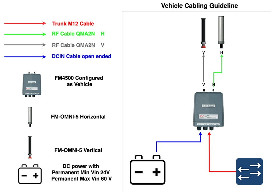
Note: The radios do not have any knowledge about Horizontal (H) and Vertical (V). It is very important to ensure that the same order for the Horizontal and Vertical polarization is maintained across the entire deployment. If the right antenna port is selected as Horizontal and the left antenna port is selected as Vertical this convention should be followed across all radios in a given deployment. If not it will result in cross-polarization and signal degradation.
Haul-Truck Radio Installation
Figure 47 Hauler onboard setup – Dual Radios with directional antennas
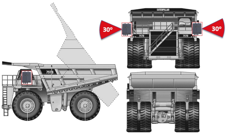
Install the radios and antennas in a way that guarantees clear line of sight with the access layer radios. Avoid vibrations and pole swings. Install RF cables out of the way of damage, and make sure all cable connectors are waterproofed. Vehicle-mounted radios must be installed inside an FM-SHIELD ruggedized enclosure.
Figure 48 Haul Truck Installation - Dual Radios with OMNI-5-KIT omni-directional antennas
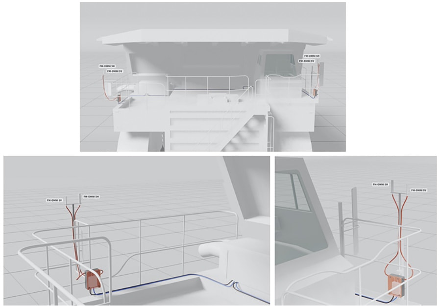
This image above depicts a typical dual-radio installation on a haul truck. Note that all antennas have been installed on the same lateral plane, and at the extreme corner points of the truck, allowing a theoretical maximum of 270 degrees of omnidirectional coverage from each antenna.
This other two images depict a close-up of one of the radios from the typical dual-radio installation shown in the previous image. Note that, since the radio is installed in an outdoor environment, it is installed inside an FM-SHIELD. Also note that the Ethernet and power connections to the radio unit are grouped together and secured out of the way of accidental snagging and damage, that the antenna cabling has been given the same treatment by being secured to hand railings, and that the omnidirectional antennas in use are mounted in perfect vertical orientation, with no line-of-sight issues.
Figure 49 Example FM4500 and OMNI-KIT-5 Antenna installation on the side of a Haul Truck
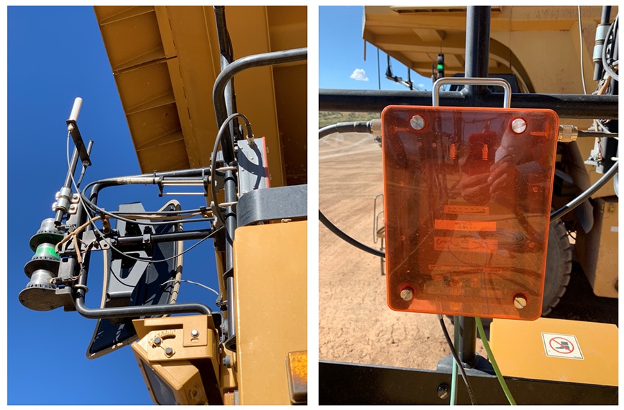
Dozer Radio Installation
Figure 50 Dozer on board setup – Single Radio with dual-polarity omni-directional antenna
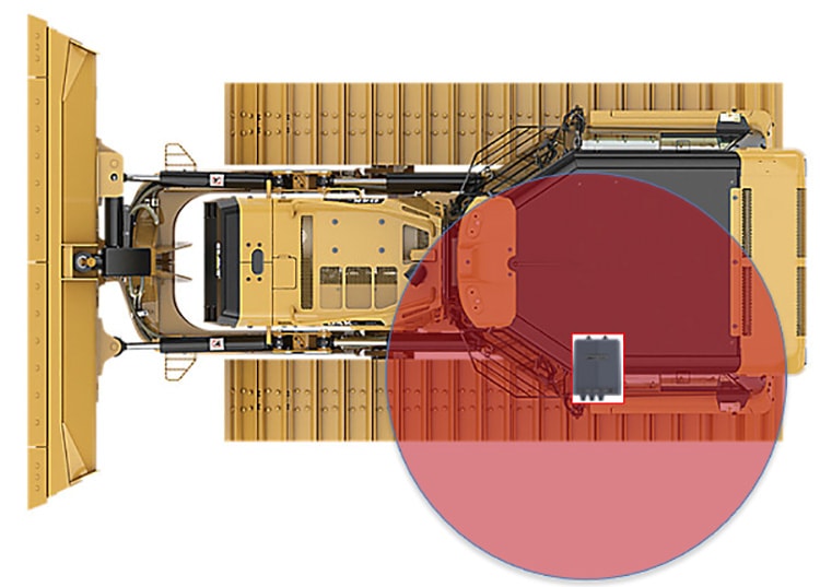
Figure 51 Dozer installation with a single radio and omni-directional antenna

This image above depicts a typical single-radio installation on a mining dozer. Note that both omnidirectional antennas have been installed on the same lateral plane, and at the highest practical point on the dozer, allowing a theoretical maximum of 360 degrees of coverage from the antennas.
Figure 52 Example of Dozer with a Single Radio and OMNI-5-KIT Antenna installed on the top
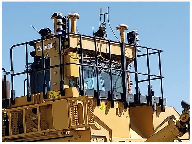
Drill Radio Installation
Figure 53 Drill with dual radios installed diagonally opposite to each other

This image shows a typical dual-radio installation on a drill. Note that the antennas have been installed at diagonally opposite corner points on the rig, allowing a theoretical 360 degrees of omnidirectional coverage.
Figure 54 Actual install of a CURWB radio with dual-polarized Omni-directional antenna

The image above depicts a close-up of omnidirectional antennas used in an actual radio installation. Note the elevated physical mounting of the antennas: in combination with no obstacles in the antenna radiation patterns, this allows maximum coverage from both antennas (Horizontally-polarized and Vertically-polarized), increasing reliability.
Mining Light Utility Vehicle
Figure 55 Mining Light Utility Vehicle Radio Installation with Omni-directional antenna
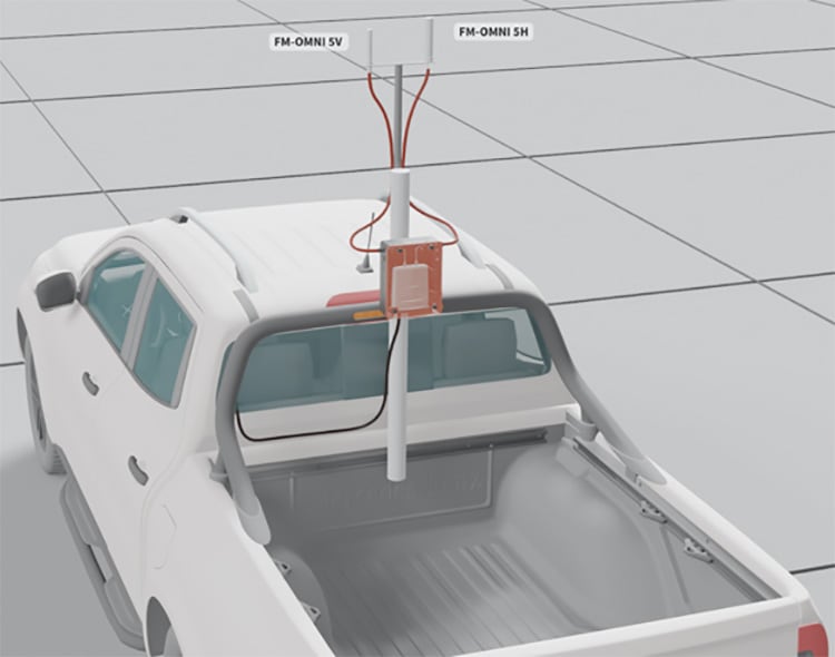
This image above depicts a typical single-radio installation on a mining light utility vehicle. Note that both omnidirectional antennas have been installed on the same lateral plane, and at the highest practical point on an auxiliary radio mast, allowing a theoretical maximum of 360 degrees of coverage from the antennas.
Antenna Cabling Installation Best-Practices
Figure 56 Cabling Installation Best Practices
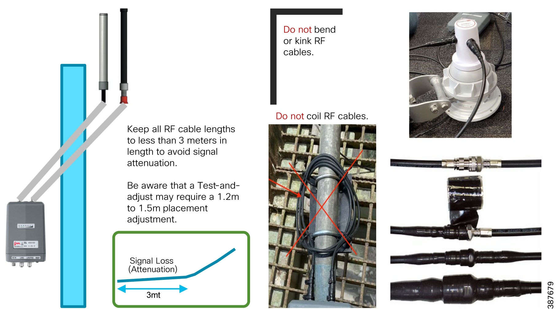
■![]() Try to keep all RF cable lengths to < 3 meters in length to avoid signal attenuation
Try to keep all RF cable lengths to < 3 meters in length to avoid signal attenuation
■![]() Leave the water protection caps on for all the unused M12 connectors
Leave the water protection caps on for all the unused M12 connectors
■![]() Always check that the coaxial and ethernet cables are connected to the device to avoid environmental exposure of the connectors
Always check that the coaxial and ethernet cables are connected to the device to avoid environmental exposure of the connectors
■![]() Do not bend, kink or coil RF cables
Do not bend, kink or coil RF cables
■![]() Apply water insulating material over the RF connectors (e.g. self-shrinking tape)
Apply water insulating material over the RF connectors (e.g. self-shrinking tape)
Antenna Alignment
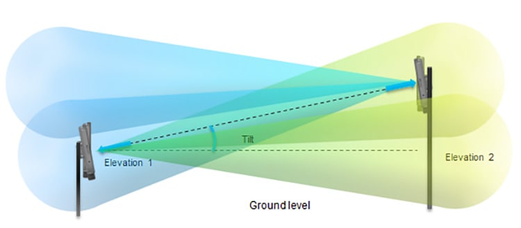
■![]() The elevation angle of each radio antenna must be kept in mind when checking the line-of-sight for each radio link. The relative height of the antenna installation must be well above ground level to eliminate any Fresnel zone blockages.
The elevation angle of each radio antenna must be kept in mind when checking the line-of-sight for each radio link. The relative height of the antenna installation must be well above ground level to eliminate any Fresnel zone blockages.
■![]() If the relative height of an antenna installation changes, the antennas at both ends must be re-aligned to regain perfect line-of-sight and a clear Fresnel zone.
If the relative height of an antenna installation changes, the antennas at both ends must be re-aligned to regain perfect line-of-sight and a clear Fresnel zone.
Site Survey and Coverage Analysis using FluidSTATS and USB GPS
■![]() FluidSTATS installed on a laptop
FluidSTATS installed on a laptop
■![]() Mobile Radio and Laptop connected to the same onboard switch
Mobile Radio and Laptop connected to the same onboard switch
■![]() FluidSTATS receiving statistical information from mobile radio
FluidSTATS receiving statistical information from mobile radio
■![]() External USB GPS connected to the laptop running FluidSTATS
External USB GPS connected to the laptop running FluidSTATS
■![]() GPS Serial and speed settings configured within FluidSTATS Settings pane
GPS Serial and speed settings configured within FluidSTATS Settings pane
■![]() FluidSTATS receiving GPS data
FluidSTATS receiving GPS data
Note: When performing a multi-frequency site survey a mobile radio will be required onboard for each frequency used on the access layer. All onboard radios need to be connected to the same switch along with the laptop with FluidSTATS.
Once FluidSTATS is receiving GPS data and statistical information from a mobile radio then drive testing can begin and a capture can be taken to gather the site survey data.
Steps to Capture Site Survey Data:
1.![]() Press the Start capture button to start the capture
Press the Start capture button to start the capture
2.![]() Start driving in the area to be surveyed with the mobile radio, laptop with FluidSTATS installed with the GPS antenna.
Start driving in the area to be surveyed with the mobile radio, laptop with FluidSTATS installed with the GPS antenna.
3.![]() Once the site survey is complete press the Stop capture button.
Once the site survey is complete press the Stop capture button.
4.![]() A FluidSTATS pop-up box will appear so the file can be named. Save the file. If the file is not saved at this point the information will be lost and the site survey will need to be repeated. Ensure that the FluidSTATS application has the required permissions to save the capture file someplace on the laptop filesystem.
A FluidSTATS pop-up box will appear so the file can be named. Save the file. If the file is not saved at this point the information will be lost and the site survey will need to be repeated. Ensure that the FluidSTATS application has the required permissions to save the capture file someplace on the laptop filesystem.
5.![]() If the capture is successful two files will be generated, a file with a.pcap extension and a file with a.gps extension
If the capture is successful two files will be generated, a file with a.pcap extension and a file with a.gps extension
6.![]() These will need to be post processed using the CURWB tools, they will generate graphs (RSSI vs. Throughput, Handoffs, etc.) and a.kml file
These will need to be post processed using the CURWB tools, they will generate graphs (RSSI vs. Throughput, Handoffs, etc.) and a.kml file
7.![]() Open the.kml file. The.kml file can be opened using multiple programs. In this example it will be opened in Google Earth Pro.
Open the.kml file. The.kml file can be opened using multiple programs. In this example it will be opened in Google Earth Pro.
Note: Once the FluidSTATS capture file has been created contact your Cisco Technical Sales Engineer to help post-process the capture file to generate the coverage map and wireless KPI graphs.
Review Site Survey Data
The site survey data is overlayed on a map of the area corresponding to the GPS location. The data is broken down in the following sections and any combination of the data can be selected to view at one time.
The figure below depicts the output of a sample site survey conducted. As can be seen we have pretty good coverage all along the path where we expect the vehicle to be driving during production. This is the aggregate RSSI and coverage we receive from all the wayside access radios. The small circles with numbers besides them indicate the locations along the path where-in the vehicle radio performed a handoff from one access radio to another.
Figure 58 Site Survey Current RSSI and Handoffs
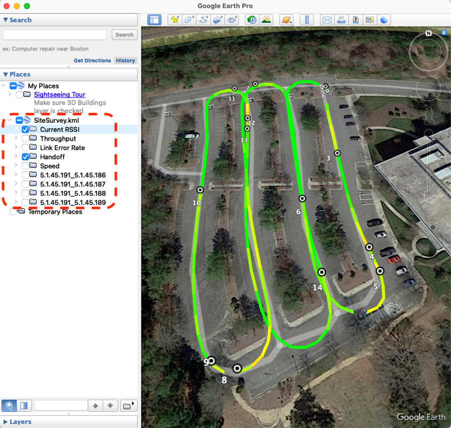
From the data collected we also have the ability to drill down further to view the RSSI and coverage provided by a single radio or a subset of wayside access radios. This can be achieved by selecting the Mesh ID of the radio(s) we are interested in on the left-hand pane of the Google Earth Pro application as depicted in the figure below.
Figure 59 Single Frequency Site Survey – Individual AP RSSI/Coverage Map and Handoffs
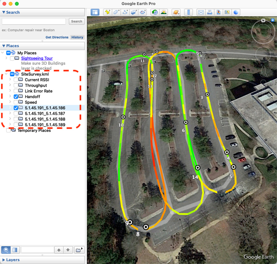
Figure 60 Multi-Frequency Site Survey Current AP RSSI Coverage Map and Handoffs
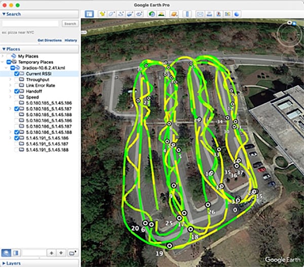
When drilling down to see the coverage a specific AP or frequency select only the Mesh ID(s) that you are interested on the left. With this method there will be empty combinations of Mobile Radio Mesh ID to Access Radio Mesh IDs, this is expected and can be ignored.
Figure 61 Multi-Frequency Site Survey Individual AP RSSI & Handoff
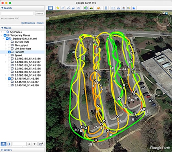
Based on the site-survey results we can determine if we have appropriate coverage in the desired areas and what sort of RSSI we can expect. If the results are not satisfactory in order to satisfy our intended application and throughput requirements, we can modify the following and re-run the site survey to see if we get improved results:
■![]() Wayside Radio/antenna placements
Wayside Radio/antenna placements
FluidSTATS and FluidREC Tools for Live RF Analysis and Troubleshooting
This section describes how to install and operate the FluidSTATS and FluidREC products. Screenshots shown in this section are explanatory examples and may be different from the ones that appear when you run the software.
Fluidity Statistics Protocol
Mobile radios must be configured to send telemetry data to the host PC running FluidSTATS. Mobile radio units running Fluidity support the transmission of a network data stream to provide real-time telemetry statistics regarding the status and the performance of the vehicular connection to listening applications.
The stream is generated by the primary mobile unit of a vehicle at a rate of 4 packets per second (one packet every 250 mSec). It consists of a flow of UDP packets transmitted to a specified IP address and port. To enable the transmission of the stream, please run the following commands on the CLI of the mobile primary unit:
■![]() fluidity monitor <destination IP address> [destination UDP port]
fluidity monitor <destination IP address> [destination UDP port]
If the destination port is not specified, the default value of 30000 will be used. The source port is set to 647 and the source IP address of the packets is the IP address of the mobile primary unit.
FluidSTATS and FluidREC Software Download & Installation
Download the latest version of FluidSTATS and FluidREC for your operating system from partners.fluidmesh.com. Both software are compiled for: Windows, MAC, Linux operating systems. Once downloaded, un-zip the archive file. Both software can be opened by double-clicking on their executable files.
FluidSTATS
FluidSTATS allows live monitoring of the wireless network through an easy and accessible user interface. FluidSTATS is the recommended software during the commissioning phase of a project. While connected to a GPS antenna mounted on board a vehicle FluidSTATS can track the main parameters along the drive path to create a site survey providing an idea of the RF coverage.
Open the GUI by double-clicking on the corresponding executable file. Several options are available within the FluidSTATS GUI as depicted in the figure below.
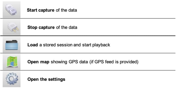
The figure below depicts the basic configuration of the system. This settings page can be displayed by clicking on ‘Preferences’ button or in the main top menu. The following parameters must be specified for the normal operations:
■![]() GPS serial device to be used to gather GPS position during the test (the GPS external device must be connected and configured before opening the software)
GPS serial device to be used to gather GPS position during the test (the GPS external device must be connected and configured before opening the software)
■![]() Serial Port Speed of the GPS device (typical speed is 4800 or 9600 baud)
Serial Port Speed of the GPS device (typical speed is 4800 or 9600 baud)
■![]() UDP port used by the radio to send telemetry packets for the testing (default is 30000)
UDP port used by the radio to send telemetry packets for the testing (default is 30000)
■![]() Multicast Group telemetry packets from the radio can be configured for multicast destination address
Multicast Group telemetry packets from the radio can be configured for multicast destination address
■![]() Multicast Interface if in use, the network interface to receive multicast traffic can be specified
Multicast Interface if in use, the network interface to receive multicast traffic can be specified
Figure 63 FluidSTATS Application Settings
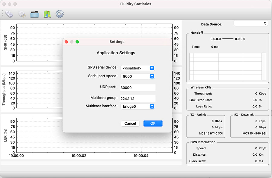
After the system is properly configured and the mobile unit is under coverage of the wireless access network several parameters can be monitored in real time including: the SNR received from each access radio unit, Link Error Rate (LER), Packet Error Rate (PER), Throughput, Handoff time, MCSs and GPS position as described in detail in the following sections.
FluidSTATS Data Source
On the top-right side of the pane, there is a drop-down box that is used to select the Data Source. The Data Source list will automatically be populated with any radio FluidSTATS is currently receiving data from. The Data Source will show as the IP address of the radio.
Figure 64 FluidSTATS Data Source
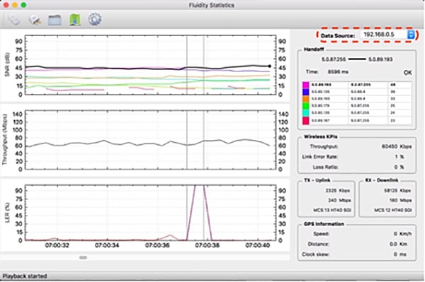
FluidSTATS Handoff
The Handoff section shows the Mesh IDs of the APs with the strongest signal. The radio Mesh ID in bold is the active and current AP selected by the vehicle. It also gives an indication of the “control plane” handoff time, in milliseconds, and whether the latest handoff was successful. Please note that, thanks to the Make-Before-Break Fluidity technology, the handoff at the ‘data plane’ is seamless and cannot be reported. Therefore, the handoff time reading is only meant to detect potential issues related to the coverage or to external interference.
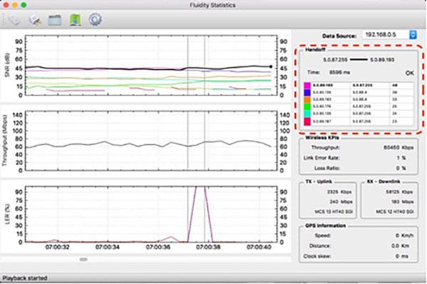
FluidSTATS Wireless KPIs
The Instantaneous Throughput (in Kbps or Mbps) is reported on the right-hand side of the chart. Two additional indicators for the Link Error Rate and the Loss Ratio are shown. The Link Error Rate (LER) is a synthetic KPI indicator that is a ratio of the un-acknowledged transmitted packets over the total transmitted packets. Un-acknowledged packets are typically retransmitted several times at the MAC layer during normal transmission operations.
The Loss Ratio (Packet Error Rate – PER) represents the ratio between the number of packets dropped and the total number of packets transmitted. Transmitted packets are dropped when the maximum number of MAC layer retransmissions allowed is exceeded.
The tool also reports the split of the uplink TX throughput (traffic from vehicle to wayside) and downlink RX throughput (traffic from wayside to vehicle) as well as Modulation speed (MCS) and MCS scheme (ex: MCS 14 HT40 LGI => Modulation and Coding Speed 14 with 40 MHz channel and Large Guard Intervals).
Figure 66 FluidSTATS Wireless KPIs
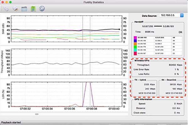
FluidSTATS GPS Information
An external USB GPS device can be connected and synced to FluidSTATS. The software will record and sync GPS data with the statistical information received from the wireless network.
Figure 67 FluidSTATS GPS Information
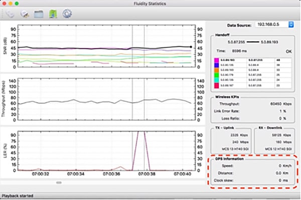
FluidSTATS SNR Plot
The SNR (Signal to Noise Ratio) plot shows the strongest signals as seen by the vehicle radio. The black line shows the signal of the AP connected to the vehicle radio and it is usually the upper envelop of the SNR lines. Vertical grey lines indicate the HANDOFFs the vehicle radio is making as the vehicle moves around.

FluidSTATS Throughput
The Throughput plot shows the total aggregate throughput passing through the wireless interface of the radio on the vehicle. This throughput is measured at Layer 2 and therefore it has a slightly higher variability compared to the throughput measured at the application layer. The chart shows the Total Throughput: Uplink and Downlink summed up together.
Figure 69 FluidSTATS Throughput
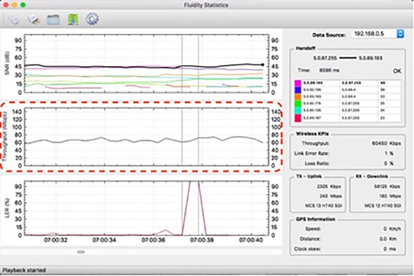
FluidSTATS LER
As described in the previous section, the Link Error Rate (LER) indicates the quality of the wireless transmission. The higher the LER, the higher the latency of the network. Usually, a LER lesser than 30% indicates that there is no visible degradation of network performance. Spikes in LER are typical in mobility scenarios as compared to fixed wireless infrastructure links.
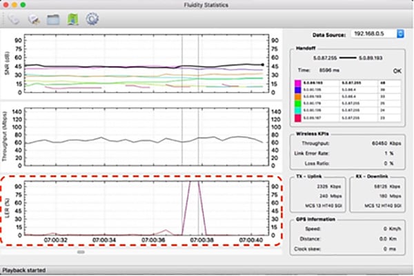
FluidREC
FluidREC is a stand-alone version of FluidSTATS and can be executed in the background allowing automatic monitoring and recording of the most important KPIs of the wireless network. FluidREC can be run on a small computer and left on-board on a vehicle for several days.
Several options are available to start and stop the recordings and split the record into multiple files. External GPS devices can be configured as well. Recorded files produced by FluidREC can be fed to FluidSTATS to playback the recorded data for offline analysis.
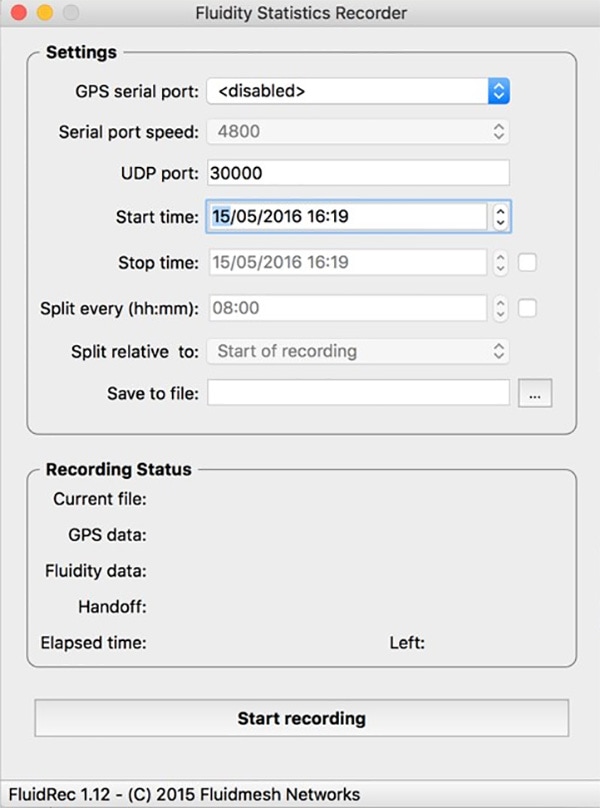
Chapter 4: Solution Implementation Guide
This section describes how to implement the CURWB wireless network design considerations of the previous sections. Discussion includes the configuration of the network infrastructure, CURWB RACER configuration tool, CURWB devices, and monitoring tools. These included configurations have been were validated during the testing effort.phase.
Note: For security reasons, the specific VLANs and IP addresses shown used in this configuration code guide are for example purposes and should not be copied directly to customer environments for security reasons.
Topology
The following Single Frequency and Multi-Frequency topologies are used as a referenced for in the design discussions.
Figure 72 Single Frequency Topology
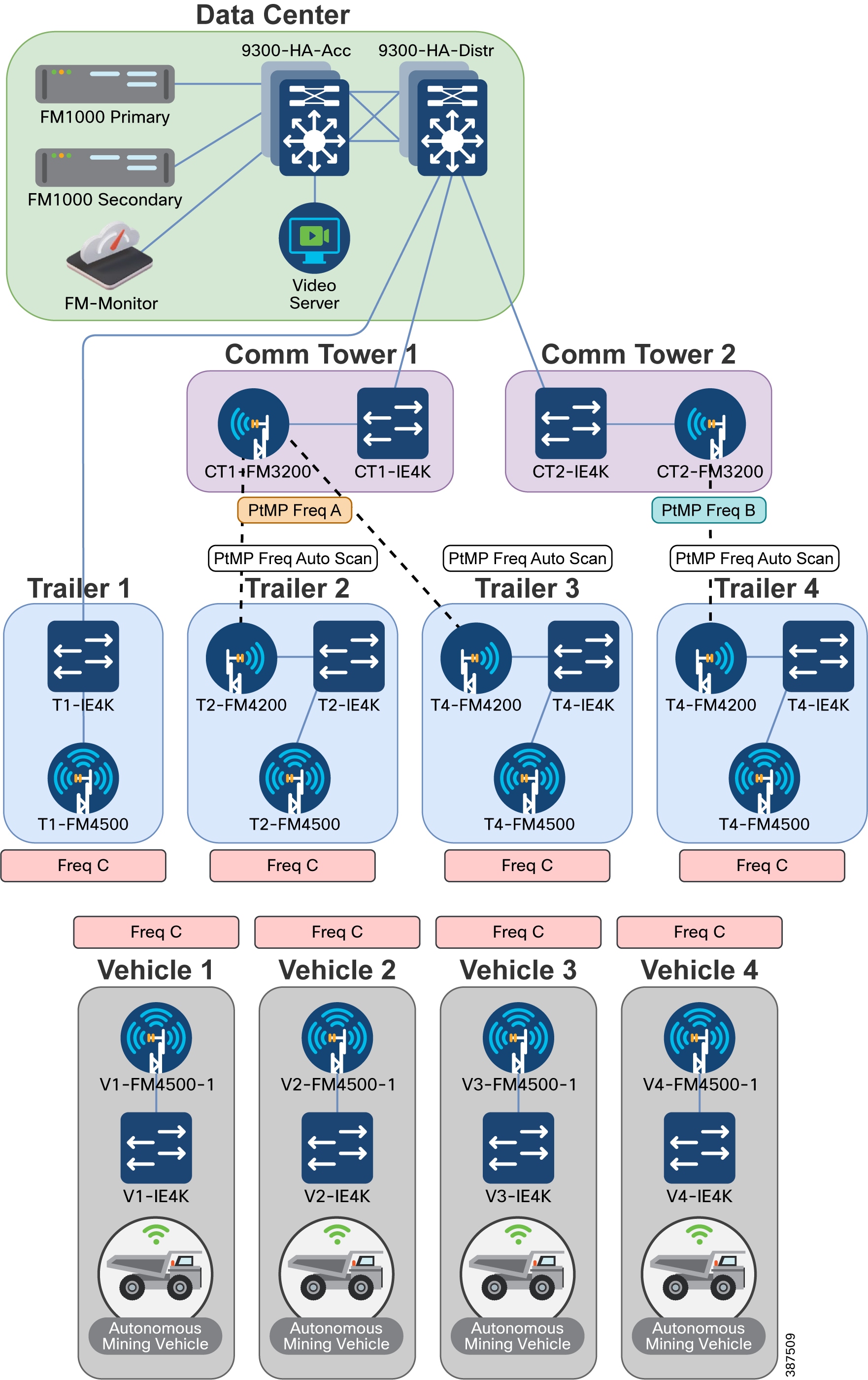
Figure 73 Multi-Frequency Topology
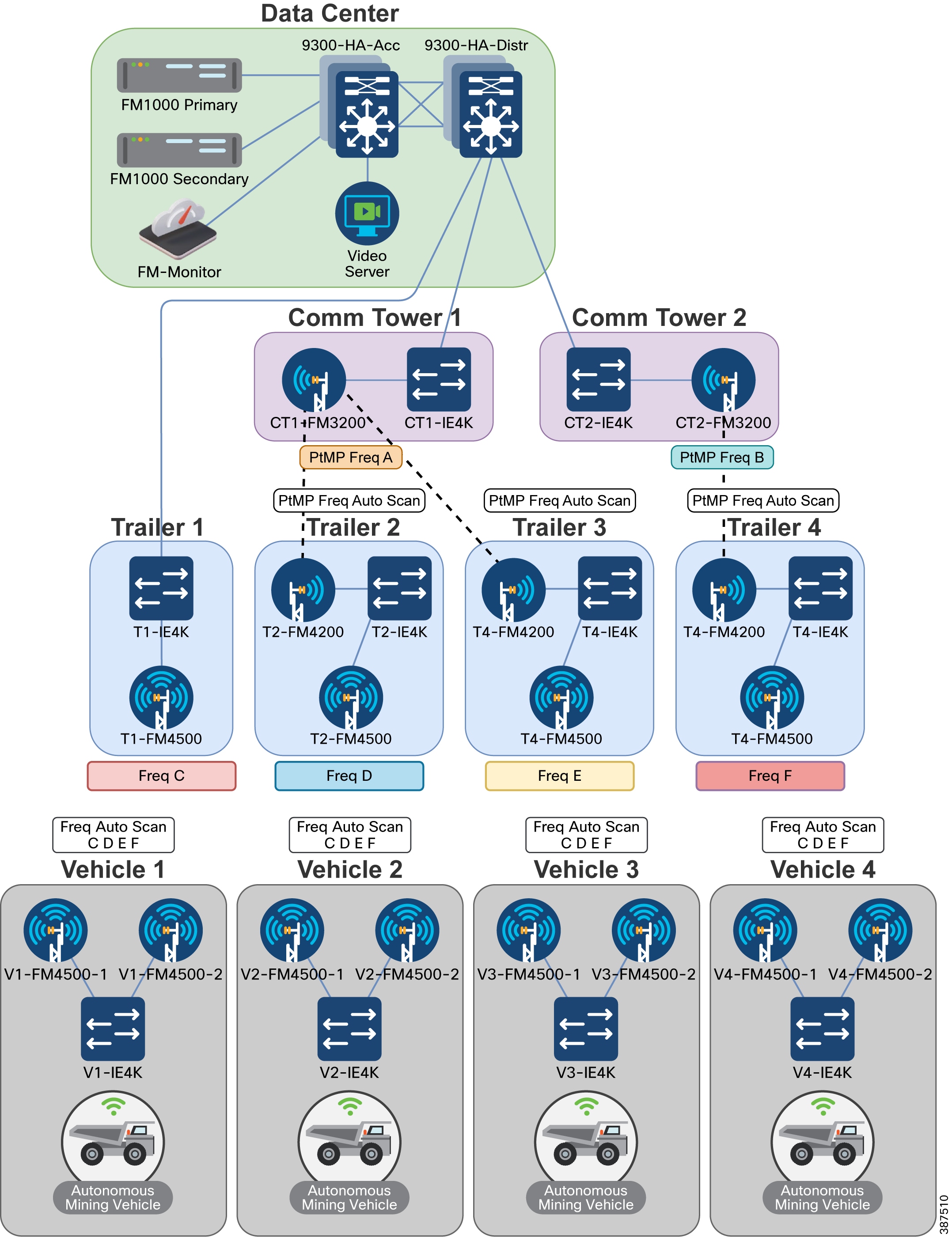
VLANs
The five VLANs used in this guide specified in the table below are traffic sources in this example.
Note: Client traffic kept must be kept separate from the Management VLAN and the infrastructure devices network.
Used for the Native VLAN on CURWB devices. This VLAN should not be used anywhere else in the network. |
||
Used to manage CURWB devices and Fluidity traffic between CURWB devices |
||
* If CURWB Native VLAN ID is set to 0, then untagged traffic is dropped.
IP Addresses and Subnet Tables
The gateway for each subnet in this example is the first IP address available in each the subnet. The device is located on the Data Center Distribution switch stack.
Infrastructure Configuration
This section describes the different components of infrastructure design. Each description includes the high-level requirements with links to more detailed steps for implementation, use, required equipment, and equipment configurations.
Layer 2 Connectivity
This design uses Layer 2 Fluidity, which means that all CURWB devices are required to be in the same Layer 2 broadcast domain.
The network must be capable of forwarding these Ethernet types: 0x8847, 0x09xx.
Ports Connected between Switches
■![]() Ports must be configured as switchports
Ports must be configured as switchports
■![]() Switchports must be configured as trunk ports
Switchports must be configured as trunk ports
■![]() Switchports must allow the VLANs being used for switch management, CURWB device management, Client traffic, and any VLANs that need to be passed across these links
Switchports must allow the VLANs being used for switch management, CURWB device management, Client traffic, and any VLANs that need to be passed across these links
■![]() Switchport native VLAN must match on both sides of the connection
Switchport native VLAN must match on both sides of the connection
Ports Connected to CURWB Devices
■![]() Ports are configured as switchports
Ports are configured as switchports
■![]() Switchports are configured as trunk ports
Switchports are configured as trunk ports
■![]() Switchports allow the VLANs being traffic used for switch management, CURWB device management, Client traffic, and all other VLANs that need to be passed across these links
Switchports allow the VLANs being traffic used for switch management, CURWB device management, Client traffic, and all other VLANs that need to be passed across these links
Configuring Switch MTU
To avoid packet fragmentation for 1500-bytes user payloads, path MTU must be greater than or equal to 1526 bytes across the network (including 4 bytes for VLANs). A minimum Ethernet frame size of 1544 bytes is required. CURWB radios can automatically detect the maximum MTU size available and enable packet fragmentation if needed.
Configuring QoS on Switches
QoS settings must be set end-to-end to trust the client markings
If the client source is not marking its own traffic with the appropriate QoS markings, then markings must be done on the switchport where the client is connected.
Configuring NTP
Devices in this network must be configured to synchronize their time with an NTP server.
Data Center Distribution Switch
The Data Center Distribution switch is a pair of switches connected with a StackWise cable for redundancy in the event of a hardware failure. The switches are logically one device, and so they share an IP address. The Data Center Distribution switch is redundantly connected to the Data Center Access switch. The distribution switch acts as the default gateway for the switches, CURWB devices, and client traffic.
Data Center Distribution Switch Configuration:
Configuration of the Switch
■![]() Configure the ports connected to other switches
Configure the ports connected to other switches
–![]() Ports should have a native VLAN
Ports should have a native VLAN
–![]() Ports should allow the VLANs being used for switch management, CURWB devices, client traffic, and any VLANs that will need to be passed across these links
Ports should allow the VLANs being used for switch management, CURWB devices, client traffic, and any VLANs that will need to be passed across these links
–![]() Ports should trust QoS markings
Ports should trust QoS markings
■![]() Configure Redundant links between switches should be configured in a port channel
Configure Redundant links between switches should be configured in a port channel
–![]() Port-channels should be trunk ports
Port-channels should be trunk ports
–![]() Port-channels should have a native VLAN
Port-channels should have a native VLAN
–![]() Port-channels should allow traffic from the VLANs being used for switch management, CURWB devices, client traffic, and all other VLAN traffics that require passage across these links
Port-channels should allow traffic from the VLANs being used for switch management, CURWB devices, client traffic, and all other VLAN traffics that require passage across these links
■![]() Configure SVI for the Switch management, CURWB devices, and Client traffic subnets
Configure SVI for the Switch management, CURWB devices, and Client traffic subnets
■![]() Configure the MTU size on the switch to a minimum of 1544 bytes
Configure the MTU size on the switch to a minimum of 1544 bytes
Distribution Switch Configuration Example
9300-HA-Distr to 9300-HA-Acc:
9300-HA-Distr to T1-IE4K:
9300-HA-Distr to CT1-IE4K:
Distribution Switch to CT2-IE4K:
9300-HA-Distr IP Addresses
9300-HA-Distr MTU
9300-HA-Distr NTP
Note: The Data Center Distribution Switch in this setup is synchronizing with an NTP server. The other devices in this setup are synchronizing their NTP to the Distribution Switch.
Data Center Access Switch
Data Center Access Switches act as the layer 2 switch that connects the Data Center Distribution Switch to Mesh End and other servers in the Data Center. The access switch consists of is a pair of switches connected with a stackwise cable for redundancy in the event of a hardware failure. The switches in this example are logically one device, so they will share an IP address. The Access switch is redundantly connected to the Distribution Switch.
Data Center Access Switch Configuration
■![]() Configure ports connected to other switches
Configure ports connected to other switches
–![]() Ports must have a native VLAN
Ports must have a native VLAN
–![]() Ports must allow the VLANs being used for switch management, CURWB devices, client traffic, and anyall other VLAN traffics that will need to be passed across these links
Ports must allow the VLANs being used for switch management, CURWB devices, client traffic, and anyall other VLAN traffics that will need to be passed across these links
–![]() Ports must trust QoS markings
Ports must trust QoS markings
■![]() Redundant links between switches should be configured in a port channel
Redundant links between switches should be configured in a port channel
–![]() Port-channels must be trunk ports
Port-channels must be trunk ports
–![]() Port-channels should must have a native VLAN
Port-channels should must have a native VLAN
–![]() Port-channels should must allow the VLANs for being used for switch management, CURWB devices, client traffic, and any other VLANs that will need to be passed across these links
Port-channels should must allow the VLANs for being used for switch management, CURWB devices, client traffic, and any other VLANs that will need to be passed across these links
■![]() Configure port connected to CURWB Devices
Configure port connected to CURWB Devices
–![]() Ports must have a native VLAN
Ports must have a native VLAN
–![]() Ports must allow the VLANs being used for switch management, CURWB devices, client traffic, and any VLANs that will need to be passed across these links
Ports must allow the VLANs being used for switch management, CURWB devices, client traffic, and any VLANs that will need to be passed across these links
–![]() Ports should must trust QoS markings
Ports should must trust QoS markings
■![]() Configure ports connected to UCS Server (Hosting FM-Monitor & other Virtual Machines)
Configure ports connected to UCS Server (Hosting FM-Monitor & other Virtual Machines)
–![]() Port must allow the VLANs being used for switch management, CURWB devices, client traffic, and any VLANs that will need to be passed across these links
Port must allow the VLANs being used for switch management, CURWB devices, client traffic, and any VLANs that will need to be passed across these links
–![]() Ports must trust QoS markings
Ports must trust QoS markings
■![]() Configure ports connected to Video Decoder Server
Configure ports connected to Video Decoder Server
–![]() Port should must be an access port
Port should must be an access port
–![]() Port should must allow the Client VLAN
Port should must allow the Client VLAN
–![]() Port should must mark the client traffic with the desired QoS marking if the client is not marking their own traffic with QoS.
Port should must mark the client traffic with the desired QoS marking if the client is not marking their own traffic with QoS.
■![]() Configure the MTU size on the switch to at least 1544 bytes
Configure the MTU size on the switch to at least 1544 bytes
Data Center Access Switch Configuration Example
9300-HA-Acc to 9300-HA-Distr:
9300-HA-Acc to FM1000-Primary:
9300-HA-Acc to FM1000-Secondary:
9300-HA-Acc to UCS Server:
9300-HA-Acc to Video Decoder Laptop
Note: This is an example ACL that matches on UDP traffic with ports between 4000-5000. The specific ACL that will be used in your environment is different, based on the type and ports of the client traffic
9300-HA-Acc IP Address
9300-HA-Acc MTU
9300-HA-Acc NTP
CURWB Mesh End
Connect each Mesh Ends to one of the physical Data Center Access switches. Only one Mesh End in the redundant pair will be active at a time. The Mesh End with the lowest Mesh ID will be the Primary Mesh End.
■![]() Assign device to RACER project
Assign device to RACER project
■![]() Verify below Plug-ins are available in project
Verify below Plug-ins are available in project
–![]() Bandwidth Plug-in type (Exact plug-in will depends on model and throughput ordered)
Bandwidth Plug-in type (Exact plug-in will depends on model and throughput ordered)
■![]() Apply Mesh End configuration template to Mesh End
Apply Mesh End configuration template to Mesh End
CURWB Mesh End Configuration Example
For additional steps on how to setup RACER and configure CURWB devices refer to the following section of the guide: CURWB Configuration
Communications Tower
Communication Towers are a central hub that has a wired connection to the data center and a wireless point-to-point or point-to-multi-point backhaul connection to downstream trailers. A communications tower comprises a backhaul radio connected to a downstream trailer and a switch connecting it to the network.
Communications towers are physically placed in the environment where they can have a wired connection to the data center and still provide clear line-of-sight wireless access to trailers.
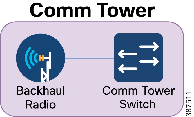
Communications Tower Configuration:
■![]() Configure ports connected to other switches
Configure ports connected to other switches
–![]() Ports must have a native VLAN
Ports must have a native VLAN
–![]() Ports must allow the VLANs being used for switch management, CURWB devices, client traffic, and all VLANs that pass across these links
Ports must allow the VLANs being used for switch management, CURWB devices, client traffic, and all VLANs that pass across these links
–![]() Ports must trust QoS markings
Ports must trust QoS markings
■![]() Configure ports connected to CURWB devices
Configure ports connected to CURWB devices
–![]() Ports must have a native VLAN
Ports must have a native VLAN
–![]() Ports must allow the VLANs being used for switch management, CURWB devices, client traffic, and any VLANs that will need to be passed across these links
Ports must allow the VLANs being used for switch management, CURWB devices, client traffic, and any VLANs that will need to be passed across these links
–![]() Ports should must trust QoS markings
Ports should must trust QoS markings
■![]() Configure SVI IP address of Switch management VLAN
Configure SVI IP address of Switch management VLAN
–![]() Configure the MTU size on the switch to a minimum 1544 bytes
Configure the MTU size on the switch to a minimum 1544 bytes
■![]() Assign the device to RACER project
Assign the device to RACER project
■![]() Verify that the Plug-ins listed below are available in the project
Verify that the Plug-ins listed below are available in the project
–![]() FM-UNII2 (Applies only for USA)
FM-UNII2 (Applies only for USA)
–![]() Bandwidth Plug-in type (Exact plug-in will depends on model and throughput ordered)
Bandwidth Plug-in type (Exact plug-in will depends on model and throughput ordered)
■![]() Apply Backhaul Radio configuration template to the radio
Apply Backhaul Radio configuration template to the radio
Communications Tower Switch Configuration Example:
CT1-IE4K to 9300-HA-Distr
CT1-IE4K to CT1-FM3200
CT1-IE4K IP Address
CT1-IE4K Default Gateway
CT1-IE4K MTU
CT1-IE4K NTP
CURWB Backhaul Radio Configuration Example
For additional steps on how to setup RACER and configure CURWB devices refer to: CURWB Configuration.
Trailer
Trailers provide wireless connectivity to vehicles and relay that data to a communications tower through either a fiber link or a a point-to-point or point-to-multipoint wireless backhaul. A trailer consists of an access radio to provide connectivity to vehicles, a backhaul radio to connect to the communications tower, and a switch to connect them radios to each other. Trailer 1 in this guide uses a wired backhaul connection because it is physically close to the Communications Tower.
Trailers are placed strategically throughout the environment to provide adequate coverage to vehicles.
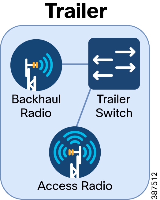
Trailer Configuration
Configuration of the Switch
■![]() Configure ports connected to CURWB devices
Configure ports connected to CURWB devices
–![]() Ports must have a native VLAN
Ports must have a native VLAN
–![]() Ports must allow the VLANs being used for switch management, CURWB devices, client traffic, and all VLANs that pass across these links
Ports must allow the VLANs being used for switch management, CURWB devices, client traffic, and all VLANs that pass across these links
–![]() Ports should trust QoS markings
Ports should trust QoS markings
■![]() Configure SVI IP address of Switch management VLAN
Configure SVI IP address of Switch management VLAN
■![]() Configure the MTU size on the switch to a minimum 1544 bytes
Configure the MTU size on the switch to a minimum 1544 bytes
–![]() Assign the device to a RACER Project
Assign the device to a RACER Project
–![]() Verify that these Plug-ins are available in the project: FM-AES, FM-TITAN, FM-UNII2 (Applies only for USA), FM-VLAN, PMCL or PTP Plug-in type (Exact plug-in will depends on model and throughput ordered) [Use PTP type for Point-to-Point connections, Use PMCL type for Point-to-Multi-Point connections]
Verify that these Plug-ins are available in the project: FM-AES, FM-TITAN, FM-UNII2 (Applies only for USA), FM-VLAN, PMCL or PTP Plug-in type (Exact plug-in will depends on model and throughput ordered) [Use PTP type for Point-to-Point connections, Use PMCL type for Point-to-Multi-Point connections]
–![]() Apply Backhaul Radio configuration template to the radio
Apply Backhaul Radio configuration template to the radio
–![]() Apply device-specific configuration to radio
Apply device-specific configuration to radio
–![]() Apply RACER config to the Backhaul Radio
Apply RACER config to the Backhaul Radio
–![]() Assign the device to the RACER project
Assign the device to the RACER project
–![]() Verify these Plug-ins are available in the project: FM-AES, FM-TITAN, FM-UNII2 (Applies only for USA), FM-VLAN, Fluidity-Bandwidth Trackside Plug-in type (Exact plug-in will depends on model and throughput ordered) [Use PTP type for Point-to-Point connections, Use PMCL type for Point-to-Multi-Point connections]
Verify these Plug-ins are available in the project: FM-AES, FM-TITAN, FM-UNII2 (Applies only for USA), FM-VLAN, Fluidity-Bandwidth Trackside Plug-in type (Exact plug-in will depends on model and throughput ordered) [Use PTP type for Point-to-Point connections, Use PMCL type for Point-to-Multi-Point connections]
–![]() Apply Backhaul Radio configuration template to the radio
Apply Backhaul Radio configuration template to the radio
Trailer Switch Configuration Example
CURWB Backhaul Radio and Access Radio Configuration Example
For additional steps on how to setup RACER and configure CURWB devices refer to the following section of the guide: CURWB Configuration.
Vehicles
Vehicles are the mobile equipment that must access to the network. The mobile radio onboard the vehicle connects to the trailers as the vehicle moves throughout the environment. A vehicle consists of a mobile radio to that connects to the trailer access radio of a trailer, the equipment on-board the vehicle that has network access, and a switch that connects them to each other.
As the vehicle moves around the environment, the vehicle range should not extend beyond the coverage of the trailer access radios.
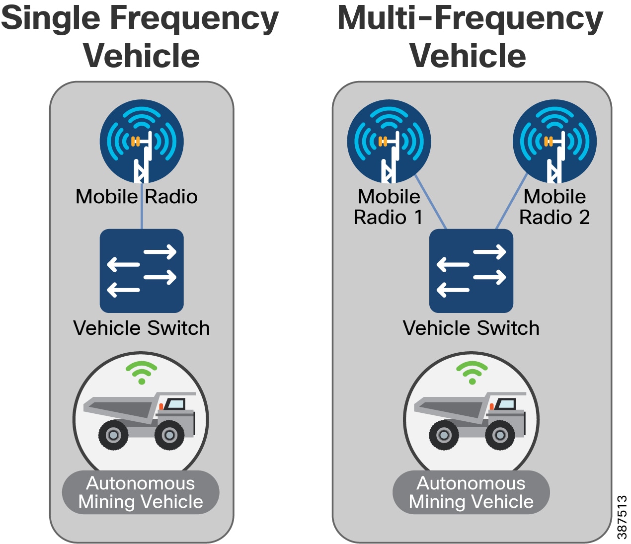
Vehicle Configuration
Configuration of the Switch
■![]() Configure ports connected to CURWB devices
Configure ports connected to CURWB devices
–![]() Ports must have a native VLAN
Ports must have a native VLAN
–![]() Ports must allow access to the VLANs being used for switch management, CURWB devices, client traffic, and all VLANs that need to be passed across these links
Ports must allow access to the VLANs being used for switch management, CURWB devices, client traffic, and all VLANs that need to be passed across these links
–![]() Ports must trust QoS markings
Ports must trust QoS markings
■![]() Configure ports connected to client devices
Configure ports connected to client devices
–![]() Ports must allow the VLAN used for client traffic
Ports must allow the VLAN used for client traffic
–![]() Port must mark the client traffic with the desired QoS marking if the client is not marking their own traffic with QoS.
Port must mark the client traffic with the desired QoS marking if the client is not marking their own traffic with QoS.
■![]() Configure the SVI IP address of Switch management VLAN
Configure the SVI IP address of Switch management VLAN
■![]() Configure the Default Gateway
Configure the Default Gateway
■![]() Configure the MTU size on the switch to a minimum 1544 bytes
Configure the MTU size on the switch to a minimum 1544 bytes
■![]() CURWB Mobile Radio Primary Setup
CURWB Mobile Radio Primary Setup
–![]() Assign the device to the RACER Project
Assign the device to the RACER Project
–![]() Verify that the Plug-ins listed are available in the project: FM-AES, FM-TITAN, FM-UNII2 (Applies only for USA), FM-VLAN, Fluidity-Bandwidth Mobile Plug-in type (Exact plug-in will depends on model and throughput ordered) [Use PTP type for Point-to-Point connections, Use PMCL type for Point-to-Multi-Point connections]
Verify that the Plug-ins listed are available in the project: FM-AES, FM-TITAN, FM-UNII2 (Applies only for USA), FM-VLAN, Fluidity-Bandwidth Mobile Plug-in type (Exact plug-in will depends on model and throughput ordered) [Use PTP type for Point-to-Point connections, Use PMCL type for Point-to-Multi-Point connections]
–![]() Apply Mobile Radio configuration template to the radio
Apply Mobile Radio configuration template to the radio
–![]() Apply device specific configuration to the radio
Apply device specific configuration to the radio
–![]() Apply RACER config to the Mobile Radio Primary
Apply RACER config to the Mobile Radio Primary
■![]() CURWB Mobile Radio Secondary Setup
CURWB Mobile Radio Secondary Setup
–![]() Assign device to RACER Project
Assign device to RACER Project
–![]() Verify that the Plug-ins listed are available in the project: FM-AES, FM-TITAN, FM-UNII2 (Applies only for USA), FM-VLAN, Fluidity-Bandwidth Mobile Plug-in type (Exact plug-in will depends on model and throughput ordered), [Use PTP type for Point-to-Point connections, Use PMCL type for Point-to-Multi-Point connections]
Verify that the Plug-ins listed are available in the project: FM-AES, FM-TITAN, FM-UNII2 (Applies only for USA), FM-VLAN, Fluidity-Bandwidth Mobile Plug-in type (Exact plug-in will depends on model and throughput ordered), [Use PTP type for Point-to-Point connections, Use PMCL type for Point-to-Multi-Point connections]
–![]() Apply Mobile Radio configuration template to radio
Apply Mobile Radio configuration template to radio
Vehicle Switch Configuration Example
Note: This is an example ACL that matches on UDP traffic with ports between 4000-5000. Your specific ACL that will be used may be different based on the type and ports of the client traffic being sent.
CURWB Mobile Radio Configuration Example
For additional steps on how to setup RACER and configure CURWB devices refer to the following section of the guide:
CURWB Configuration
This section explains how to setup the CURWB devices using RACER generated device configuration files and applying them to the devices offline using the Configurator (GUI).
This document does not provide a complete configuration guide for RACER and does not cover all possible scenarios on how the RACER product can be used. For more information, refer to the RACER documentation page at the following URL:
https://www.cisco.com/c/en/us/support/wireless/ultra-reliable-wireless-backhaul/series.html#~tab-documents
RACER – Radio Configuration Environment
Access RACER from the CURWB Partners Portal. Register an account on the Partners Portal, and then you can access all the radios, licenses and configuration templates associated with all your projects at a single location.
The following RACER configuration steps are described in this section:
■![]() Accessing the CURWB Partners Portal
Accessing the CURWB Partners Portal
■![]() Add Devices to a RACER Account Portfolio
Add Devices to a RACER Account Portfolio
■![]() Assign a CURWB Device to a Project
Assign a CURWB Device to a Project
■![]() Add Plug-Ins to a RACER Account Portfolio
Add Plug-Ins to a RACER Account Portfolio
■![]() Assign a Plug-in to a Project
Assign a Plug-in to a Project
■![]() Creating a New Configuration Template
Creating a New Configuration Template
■![]() Assign a Device Configuration Template to a Project
Assign a Device Configuration Template to a Project
■![]() Applying Plug-ins to a Device
Applying Plug-ins to a Device
■![]() Applying the Device Configuration Template to a Device
Applying the Device Configuration Template to a Device
■![]() Applying Device-Specific Configurations to a Device
Applying Device-Specific Configurations to a Device
■![]() Downloading the Configuration File and Software from RACER
Downloading the Configuration File and Software from RACER
–![]() RACER is compatible with the following CURWB hardware devices and firmware:
RACER is compatible with the following CURWB hardware devices and firmware:
–![]() Gateway devices: FM 1000, FM 10000
Gateway devices: FM 1000, FM 10000
–![]() 1.4.1 and 2.1.0 or later (FM1000 and FM10000 Gen 1 and Gen 2)
1.4.1 and 2.1.0 or later (FM1000 and FM10000 Gen 1 and Gen 2)
Accessing the CURWB Partners Portal
Access the RACER web-based interface by completing the following steps:
1.![]() Go to https://partners.fluidmesh.com/
Go to https://partners.fluidmesh.com/
The CURWB Partners Portal Sign In a dialog displays.
2.![]() Register as a portal user by clicking the Create Account link and following the software prompts.
Register as a portal user by clicking the Create Account link and following the software prompts.
Note: Registration requests must be approved before the account can access the CURWB Partners Portal. Cisco reviews your information and approves your account within the next business day.
3.![]() When registration approval is complete, you are redirected to the CURWB Partners Portal homepage.
When registration approval is complete, you are redirected to the CURWB Partners Portal homepage.
Creating a New Project
To create a new project using the Projects view, complete the following steps:
1.![]() Log on to the CURWB Partner Portal.
Log on to the CURWB Partner Portal.
2.![]() Click RACER to access the RACER interface.
Click RACER to access the RACER interface.
3.![]() Click the Projects link on the left side of the RACER interface (below).
Click the Projects link on the left side of the RACER interface (below).

4.![]() Click the Create Project button (below).
Click the Create Project button (below).
Figure 78 RACER Create Project

The Create Project dialog displays.
5.![]() Enter the project name of the project in the Name field.
Enter the project name of the project in the Name field.
6.![]() Click the Type drop-down and then select the project type.
Click the Type drop-down and then select the project type.
7.![]() If needed, enter a short description of the project in the Description field.
If needed, enter a short description of the project in the Description field.
Add Devices to the RACER Account Portfolio
To configure a CURWB device, the device must be in your RACER account portfolio.
When the purchase order for your CURWB device is finalized and you take delivery of the physical device, the device is added to your portfolio by CURWB Support. A list of the Mesh IDs and the serial numbers of the CURWB devices will need to be provided to CURWB Support.
To check that a device has been added to your RACER account portfolio, complete the following steps:
1.![]() Log on to the CURWB Partner Portal.
Log on to the CURWB Partner Portal.
2.![]() Click RACER to access the RACER interface.
Click RACER to access the RACER interface.
3.![]() Click the Configure Devices link on the left side of the FM Racer interface (below).
Click the Configure Devices link on the left side of the FM Racer interface (below).
Figure 79 RACER Configure Devices
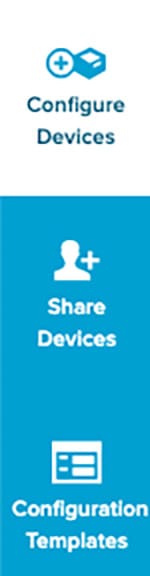
Graphical user interface, application Description is automatically generated.
• The RACER™ Radio Configuration view displays.
All registered devices are listed. See device list (below).
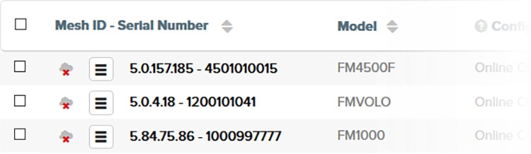
The Add Devices dialog displays.
4.![]() Click the green Add + button on the dialog (below).
Click the green Add + button on the dialog (below).

Mesh-ID and Serial Number entry fields display below the Add + button.
5.![]() Enter the correct Mesh-ID and Serial Number values in the fields.
Enter the correct Mesh-ID and Serial Number values in the fields.
6.![]() Click the blue Add Devices button on the dialog (below).
Click the blue Add Devices button on the dialog (below).

If the Mesh-ID and Serial Number values are correct, the device is added to your RACER account portfolio. You will receive an E-mail confirming that the device has been added.
Assign a CURWB Device to a Project
To associate a new or existing project with a CURWB device to a new or existing project, complete the following steps:
1.![]() Click the Configure Devices link on the left side of the FM Racer interface (below).
Click the Configure Devices link on the left side of the FM Racer interface (below).
Figure 83 RACER Configure Devices Button
Graphical user interface, application Description is automatically generated.
The RACER™ Radio Configuration view displays.
2.![]() From the device list, find the device that must be made part of for association to the new project.
From the device list, find the device that must be made part of for association to the new project.
3.![]() Enable the checkbox to the left of the device listing (below).
Enable the checkbox to the left of the device listing (below).
Figure 84 RACER Device list checkbox

4.![]() Click the Assign to Project button (below).
Click the Assign to Project button (below).
Figure 85 RACER Assign to Project

A picture containing chart Description is automatically generated.
The Assign devices to project dialog displays.
Associate the device with a project using either of the following methods.
■![]() To associate the device with an existing project, complete the following steps:
To associate the device with an existing project, complete the following steps:
1.![]() Type one or more characters from the project name in the Type project field.
Type one or more characters from the project name in the Type project field.
All project listings that contain the characters display.
2.![]() Click the correct project name to select it.
Click the correct project name to select it.
The project listing association is made.
■![]() To associate the device with a new project, complete the following steps:
To associate the device with a new project, complete the following steps:
1.![]() Click the + button. The Create Project dialog displays.
Click the + button. The Create Project dialog displays.
2.![]() In the Project Name field, type the name of the new project, and then click Create.
In the Project Name field, type the name of the new project, and then click Create.
The Assign devices to project dialog displays. Complete the dialog as shown in the sub-section above, and click the blue
The Assign devices to project dialog will be shown.
Add Plug-ins to the RACER Account Portfolio
To be able to apply plug-ins to a CURWB device, they first need to be added to your RACER Account Portfolio.
When the purchase order for your CURWB plug-ins is finalized, the plug-in is automatically added to your portfolio if the email address used to make the purchase is the same as the partners.fluidmesh.com account email. If the emails are not the same, the plug-ins can be added manually.
To check that a plug-in has been added or to add a plug-in to your RACER account portfolio, complete the following steps:
1.![]() Log on to the CURWB Partners Portal.
Log on to the CURWB Partners Portal.
When you purchase a generic 16-digit License code, the license code and corresponding plug-in name is listed on the Plug-ins page. After the generic license code is purchased, you also receive an email from plugins_fm@cisco.com containing the License code.
Figure 86 Partner Portal Plug-ins page
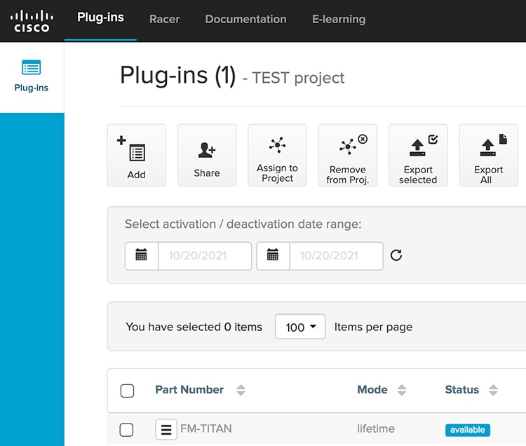
Graphical user interface, application Description is automatically generated
If the License code and corresponding plug-in are not listed on the Plug-ins page, click the Add button in the upper left-hand corner of the Plug-ins web page, and In the Enter License Code dialog. enter the License code, and then click Add License Code.
Figure 87 Figure 4 Partner Portal Plug-in/License Add
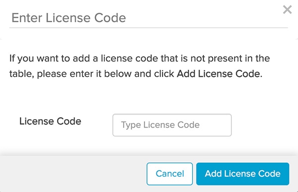
Graphical user interface, text, application description is automatically generated.
Assign a Plug-in to a Project
To add or remove a plug-in from a project using the Plug-ins view, complete the following steps:
1.![]() Log on to the CURWB Partner Portal.
Log on to the CURWB Partner Portal.
Graphical user interface, application Description is automatically generated
3.![]() Find the plug-in or plug-ins that must be added for addition to the project.
Find the plug-in or plug-ins that must be added for addition to the project.
4.![]() Enable the checkboxes to the left of the relevant plug-in listings.
Enable the checkboxes to the left of the relevant plug-in listings.
5.![]() Click the Assign to Project button (below).
Click the Assign to Project button (below).
A picture containing text Description is automatically generated.
The Assign plug-ins to project dialog displays.
Associate the plug-in with a project by doing the following steps:
To associate the plug-in with an existing project, do the following steps:
1.![]() Type one or more characters from the project name in the Type project field.
Type one or more characters from the project name in the Type project field.
All project listings that contain the characters will be shown.
2.![]() Click the correct project listing to select it.
Click the correct project listing to select it.
The project listing will be selected.
To associate the plug-in with a new project, do the following steps:
The Create Project dialog will be shown.
2. Complete the dialog as shown above, and then click the blue Create button.
The Assign plug-ins to project dialog will be shown.
3.![]() Click the blue Assign button.
Click the blue Assign button.
The plug-in will be associated with the chosen project.(See Adding a CURWB device to a project for instructions.))
Note: If a plug-in is initially associated with a different project different to a project with which it was previously associated, that association is dropped, and it is associated with the newly -selected project instead.
Alternatively, remove the plug-in from a project by doing completing the following steps:
1.![]() Deactivate the plug-in as shown in the Deactivating an active plug-in section of the CURWB Installation and Configuration manual for the specific device.
Deactivate the plug-in as shown in the Deactivating an active plug-in section of the CURWB Installation and Configuration manual for the specific device.
2.![]() Enable the checkbox to the left of the relevant plug-in listing.
Enable the checkbox to the left of the relevant plug-in listing.
3.![]() Click the Remove from Proj. button (below).
Click the Remove from Proj. button (below).

A picture containing graphical user interface Description automatically generated
The Remove Assignment dialog displays.
Applying Plug-ins to a Device
To add or remove a plug-in from a device using the Plug-ins view, do the following steps:
1.![]() Click the Configure Devices link on the left side of the RACER interface (below).
Click the Configure Devices link on the left side of the RACER interface (below).
Figure 91 RACER Configure Devices
Graphical user interface, application Description is automatically generated
• The RACER™ Radio Configuration view displays.
The lower part of the view includes a list of the devices assigned to your user profile displays in the lower part of the view (below).
Figure 92 RACER User Profile Device List
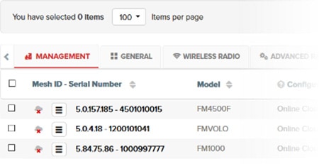
Graphical user interface, text, application, email Description are automatically generated
The configuration category tabs (Management, General, Wireless Radio, and so on) across the top of the device list contain drop-down menus with a range of configuration options that are relevant to each of your the devices. The category tabs can be horizontally scrolled from right to left.
The configuration category tabs are shown in a horizontal row above the device listings. When all devices that require configuration are shown in the Radio Configuration view, click-and-hold the right arrow to scroll the category tabs button (below).
Figure 93 Radio Configuration tabs

Chart Description is automatically generated
Scroll right until the PLUG-INS tab is shown displays. (below).
Figure 94 Radio Configuration Plug-ins tab

Graphical user interface Description automatically generated with medium confidence.
2.![]() For each plug-in displayed: Using the table below as a guide to activate the appropriate licenses for each CURWB plug-in device in the environment by clicking off toggle button or enabling the checkbox.
For each plug-in displayed: Using the table below as a guide to activate the appropriate licenses for each CURWB plug-in device in the environment by clicking off toggle button or enabling the checkbox.
Figure 95 Radio Configuration checkbox enabled
Table Description is automatically generated
After all plug-in configurations are complete, the Activate Plug-ins view displays.
3.![]() Select a plug-in from the list shown by enabling the checkbox to the left of the plug-in.
Select a plug-in from the list shown by enabling the checkbox to the left of the plug-in.
4.![]() Click Activate to activate the plug-in.
Click Activate to activate the plug-in.
Note: The specific bandwidth of the plug-in name depends on which throughput option was purchased.
Creating a New Configuration Template
FM RACER is designed to save time by speeding and simplifying the configuration of CURWB devices.
Mass configuration works on the principle that if multiple devices of a single type require configuration, a custom configuration file only needs to can be created once, using the needed parameters. After creation, the configuration file can be applied to all other devices of the same type. Minor specific configuration adjustments can be made to each device as needed.
Use the steps in this section to create the following templates:
■![]() Vehicle Mobile Radio – Single Frequency
Vehicle Mobile Radio – Single Frequency
■![]() Vehicle Mobile Radio – Multi-Frequency
Vehicle Mobile Radio – Multi-Frequency
The configuration settings for each of these templates are referenced in the following section of this guide:
RACER Configuration Template Table
After the templates have been created, they can be assigned to a project and then applied to a device.
Create and then save a new configuration template by completing the steps that follow:
1.![]() From the home page of the FM RACER application, click the Configuration Templates link on the left side of the FM Racer interface (below).
From the home page of the FM RACER application, click the Configuration Templates link on the left side of the FM Racer interface (below).
Figure 96 Configuration Templates

Graphical user interface, application, Teams Description automatically generated
The RACER™ Configuration Templates view displays.
Click the Create Template button (below).

QR code Description automatically generated
The Create Configuration Template view (below) displays.
Figure 98 Create Configuration Template view

2.![]() Click the Product Line drop-down.
Click the Product Line drop-down.
The product line options display.
3.![]() Click the correct device model listing.
Click the correct device model listing.
Note: It is important to choose the correct device model listing. The product line options are categorized by firmware version, and include different parameter sets for each model.
After the device model listing is selected, a selection of parameter sets for that model display.
4.![]() Enter a descriptive and unique name for the template in the Template name field.
Enter a descriptive and unique name for the template in the Template name field.
5.![]() Enter a written description in the Template description field.
Enter a written description in the Template description field.
Note: A detailed and unique description for using the template makes the future task of choosing and organizing templates much simpler.
The Template Name and Template description can be changed at any time.
6.![]() Use either of the following procedures to associate the template with a project.
Use either of the following procedures to associate the template with a project.
To associate the template with an existing project, complete the following steps:
a.![]() Type one or more characters from the project name in the Project name field.
Type one or more characters from the project name in the Project name field.
All project listings that contain the characters display.
b.![]() Select the correct project name, and then click Save. The template is associated with the selected project.
Select the correct project name, and then click Save. The template is associated with the selected project.
The project listing will be selected.
To associate the template with a new project, complete the following steps:
• The Create Project dialog displays.
b.![]() Enter a unique name for the new project, and then click Save. The template is associated with the new project.
Enter a unique name for the new project, and then click Save. The template is associated with the new project.
c.![]() Set the configuration parameters for each of the parameter device model by completing the steps below. The GENERAL section is shown as an example:
Set the configuration parameters for each of the parameter device model by completing the steps below. The GENERAL section is shown as an example:
–![]() Click the correct section heading under the SECTIONS block.
Click the correct section heading under the SECTIONS block.
Some of the sections are minimized. Expand the section by clicking the collapse/minimize/maximize down arrow to the right of the section heading (below).
Figure 99 RACER Template Section Heading

A picture containing text Description automatically generated
By default, all parameters and parameter sets are included in the configuration template. If you want to exclude a parameter set from the template, after you have finished specifying the necessary parameter, click the Included all switch (below) to complete the parameter selection.
Figure 100 RACER Template Heading Included All

Clicking the Included label changes it to an Excluded all label, and all parameters in the parameter set are grayed out.
If you want to exclude any single parameter that is part of a parameter set, click the Included switch (below) for that parameter.
Figure 101 RACER Template Heading Included

Graphical user interface, text, application, chat or text message Description automatically generated
The Included switch label changes to an Excluded label, and the parameter is grayed out.
Note: If single parameters and/or parameter sets are excluded from the configuration template, the those parameters cannot be modified when the template is used to create a radio configuration.
–![]() Specify each configuration parameter in the parameter set.
Specify each configuration parameter in the parameter set.
When you have finished configuring the template, click the blue Save Conf. Template button (below).
Figure 102 RACER Save Configuration Template

FM RACER now checks for any errors or conflicts in the configuration.
Note: If a configuration parameter requires a software plug-in, RACER will prompts you about the relevant plug-in requirement. The relevant plug-in is required when applying the template.
If no errors are found, the template is saved.
If errors are found, RACER will prompts you to correct the errors. To review the parameters before proceeding click the black No button on the prompt dialog, and then review and correct the configuration parameters. Errors are indicated with warning icons.
After corrections, click the blue Continue button on the prompt dialog (below) to continue.

Note: If you save a template that contains configuration errors, the errors can be corrected before the configuration is applied to a CURWB device.
Click the blue Continue button on the prompt dialog to continue.
The template is saved in the Configuration Templates page (below).
Figure 104 RACER Configuration Templates
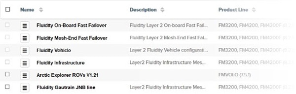
Assign a Device Configuration Template to a Project
To associate a new or existing project with a device configuration template, complete the following steps:
1.![]() Click the Configuration Templates link on the left side of the RACER interface (below).
Click the Configuration Templates link on the left side of the RACER interface (below).
Figure 105 RACER Configuration Templates Button
Graphical user interface, application, Teams Description automatically generated
• The Configuration Templates view displays.
2.![]() Identify the template that is required for the new project.
Identify the template that is required for the new project.
Note: Pre-defined templates cannot be associated with projects. Only modified and custom templates can be associated.
3.![]() Enable the checkbox to the left of the template listing (below).
Enable the checkbox to the left of the template listing (below).
Figure 106 RACER Template Checkbox
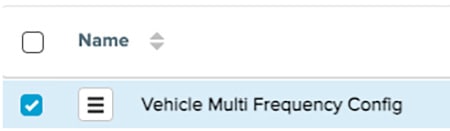
Graphical user interface, text, application Description automatically generated
4.![]() Click the Assign to Project button (below).
Click the Assign to Project button (below).
Figure 107 RACER Assign to Project Button- 387522
A picture containing text Description automatically generated
The Assign templates to project dialog displays.
Associate the template with a project by completing the following steps:
■![]() To associate the template with an existing project, do the following steps:
To associate the template with an existing project, do the following steps:
a.![]() Type one or more characters from the project name in the Type project field.
Type one or more characters from the project name in the Type project field.
• All project names that contain the characters display.
b.![]() Click the correct project name. to select it.
Click the correct project name. to select it.
The project listing is selected.
■![]() To associate the template with a new project, do the following steps:
To associate the template with a new project, do the following steps:
• The Create Project dialog displays.
b.![]() Complete the dialog as shown in the first subsection. Enter the project name, and then click the blue Create button.
Complete the dialog as shown in the first subsection. Enter the project name, and then click the blue Create button.
• The Assign templates to project dialog displays.
Applying a Configuration Template to a Device
To apply a device configuration template to a device, complete the following steps:
1.![]() Click the Configure Devices link on the left side of the RACER interface (below).
Click the Configure Devices link on the left side of the RACER interface (below).
Figure 108 RACER Configure Devices
Graphical user interface, application Description automatically generated.
• The RACER™ Radio Configuration view displays.
2.![]() Identify the device or devices for which a configuration template will need to be applied and enable the checkbox to the left of the device listing.
Identify the device or devices for which a configuration template will need to be applied and enable the checkbox to the left of the device listing.
3.![]() Enable the checkbox to the left of the device listing (below).
Enable the checkbox to the left of the device listing (below).
4.![]() Click the Apply Template button at the top of the RACER interface (below).
Click the Apply Template button at the top of the RACER interface (below).
Figure 109 RACER Apply Template

QR code Description automatically generated
The Select Configuration Template dialog displays.
Figure 110 RACER Select Configuration Template
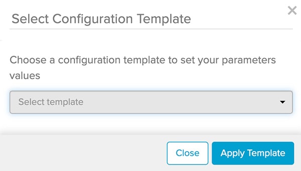
Graphical user interface, text, application, chat or text message Description automatically generated
5.![]() Type one or more characters from the configuration template name in the Select template field.
Type one or more characters from the configuration template name in the Select template field.
• All template listings that contain the characters will be shown.
6.![]() Click the correct configuration template listing to select it.
Click the correct configuration template listing to select it.
The configuration template listing will be selected.
7.![]() Click the blue Apply Template button.
Click the blue Apply Template button.
• The template will be associated with the device or devices chosen.
8.![]() Click the blue Save button to save the configuration changes.
Click the blue Save button to save the configuration changes.
• If there are any configuration errors that must be corrected, an ERROR dialog displays. Correct the errors, then save the device configuration again.
Note: All configuration issues must be resolved before the blue Save is made. Even if the Configurations button is clicked the configuration are NOT actually saved until all issues are resolved.
Applying Device-Specific Configurations to a Device
After a configuration template has been applied to a device it is necessary to apply device-specific configurations. Some examples of these might include but not limited to the following:
To apply device-specific configurations to a device, complete the steps below.
1.![]() Click the Configure Devices link on the left side of the RACER interface (below).
Click the Configure Devices link on the left side of the RACER interface (below).
Figure 111 RACER Configure Devices
Graphical user interface, application Description automatically generated
• The RACER™ Radio Configuration view will be shown.
The lower part of the view includes a list of the devices assigned to your user profile (below).
Figure 112 RACER Device List User Profile

Graphical user interface, text, application, email Description automatically generated
The category tabs above the device list contain drop-down menus with a range of configuration options that are relevant to each of your devices.
Note: Depending on the device type, some configuration options may not be available for certain devices. If a configuration option is not available for the device being configured, an Unsupported notification shown below displays.
The configuration category tabs are shown in a horizontal row above the device listings. When all devices needing for configuration are shown in the Radio Configuration view, click and hold the left arrow button (below) to scroll through the tabs.
Figure 113 RACER Radio Configuration View

Text Description automatically generated with medium confidence
• The tabs will scroll to the left until the MANAGEMENT tab is showndisplays (below).
Figure 114 RACER Management tab

To show more configuration category tabs as configuration proceeds, click or click and hold the right arrow button (below).
Figure 115 RACER Tab Navigation right arrow

2.![]() When all configurations are complete, confirm that all the configuration changes are done correctly.
When all configurations are complete, confirm that all the configuration changes are done correctly.
3.![]() Click the blue Save button on the interface to save the configuration settings.
Click the blue Save button on the interface to save the configuration settings.
Downloading Device Configuration Files and Firmware from RACER
A RACER configuration file can be applied to a single device or multiple devices that are not connected to the Internet. The devices can be in the same product line, or different product lines.
An exported configuration file in *.FMCONF format can contain configuration settings for one device or multiple devices, no matter whether the devices are of the same type or different types. Every CURWB device is capable of parsing, recognizing, and acquiring only the relevant settings for its own configuration. When downloading the *.FMCONF file from RACER, the option to include the latest device firmware inside that same file is available.
To apply a configuration file to a non-connected device, complete the following steps:
1.![]() Click the Configure Devices link on the left side of the FM RACER interface (below).
Click the Configure Devices link on the left side of the FM RACER interface (below).
Figure 116 RACER Configure Devices
Graphical user interface, application description automatically generated
• The RACER™ Radio Configuration view is shown.
2.![]() Identify the device or devices for download configuration is to be downloaded.
Identify the device or devices for download configuration is to be downloaded.
3.![]() Download the needed configuration, using either of the following methods:
Download the needed configuration, using either of the following methods:
To download only selected configurations, enable the checkbox to the left of each relevant device listing, and then click the Download selected button (below).
Figure 117 RACER Download selected

Graphical user interface, text, application Description automatically generated
4.![]() To download all configurations from all currently listed devices, click the Download All button (below).
To download all configurations from all currently listed devices, click the Download All button (below).

Graphical user interface, application, Teams Description automatically generated
The Download file view displays.
5.![]() The Download file view presents the option to enable the checkbox for Included latest firmware can be checked.
The Download file view presents the option to enable the checkbox for Included latest firmware can be checked.
6.![]() Click the blue Download button on the interface to download the file or files.
Click the blue Download button on the interface to download the file or files.
The file or files are downloaded to the chosen download location on your computer as an *.FMCONF file.
CURWB Device Initial Setup and Configuration
The following CURWB configuration steps are described in this section:
■![]() Software and Hardware Prerequisites
Software and Hardware Prerequisites
■![]() Accessing the CURWB Device for Configuration
Accessing the CURWB Device for Configuration
■![]() Local Access and Login for Initial Configuration
Local Access and Login for Initial Configuration
■![]() Switching between Offline and Online Modes
Switching between Offline and Online Modes
■![]() Uploading a Device Configuration File from RACER
Uploading a Device Configuration File from RACER
This document does not provide a complete configuration guide for CURWB devices and does not cover all possible scenarios where CURWB products may be used. For more information, refer to the CURWB documentation page at the following URL:
https://www.cisco.com/c/en/us/support/wireless/ultra-reliable-wireless-backhaul/series.html
Software and Hardware Prerequisites
To access the Configurator graphical user interface (GUI) and use the Configurator to program the CURWB device you need the following:
■![]() A desktop, laptop, or tablet computer equipped with:
A desktop, laptop, or tablet computer equipped with:
■![]() Any current Microsoft Windows, Mac OS, or Linux operating system.
Any current Microsoft Windows, Mac OS, or Linux operating system.
■![]() A CAT5/6 Ethernet cable with an RJ45 connector at one end, and depending on device model, either a M12 X-code connector or a RJ45 connecter at the other end.
A CAT5/6 Ethernet cable with an RJ45 connector at one end, and depending on device model, either a M12 X-code connector or a RJ45 connecter at the other end.
Accessing the CURWB Device for Configuration
Before the unit can be made part of a wireless network, it must be configured.
The on-board Configurator can be used to configure a CURWB device in either of two ways:
■![]() Method 1: By connecting a control device directly to the CURWB device using an Ethernet cable (Local access)
Method 1: By connecting a control device directly to the CURWB device using an Ethernet cable (Local access)
■![]() Method 2: By connecting a control device to the CURWB device through an Internet connection (Internet access)
Method 2: By connecting a control device to the CURWB device through an Internet connection (Internet access)
Local Access and Login for Initial Configuration
To use the Configurator interface to access the CURWB device directly, complete the steps that follow:
1.![]() Power the unit ON. Wait approximately one minute for the boot sequence to complete.
Power the unit ON. Wait approximately one minute for the boot sequence to complete.
2.![]() Connect one end of a CAT5/6 Ethernet cable to the computer that will be used to configure the CURWB device.
Connect one end of a CAT5/6 Ethernet cable to the computer that will be used to configure the CURWB device.
3.![]() Connect the other end of the Ethernet cable to the CURWB device.
Connect the other end of the Ethernet cable to the CURWB device.
4.![]() Manually set the computer IP address and Netmask to be in the same subnet as the CURWB device. The CURWB device will use the following setting by default and after being factory reset:
Manually set the computer IP address and Netmask to be in the same subnet as the CURWB device. The CURWB device will use the following setting by default and after being factory reset:
–![]() Launch the computer web browser.
Launch the computer web browser.
5.![]() Enter the IP address of the CURWB device in the browser URL entry field.
Enter the IP address of the CURWB device in the browser URL entry field.
–![]() If the Configurator interface displays immediately, proceed to step 9 below.
If the Configurator interface displays immediately, proceed to step 9 below.
–![]() Alternatively, you may see the following window displays:
Alternatively, you may see the following window displays:
Figure 119 'Connection Not Private' warning (Google Chrome)
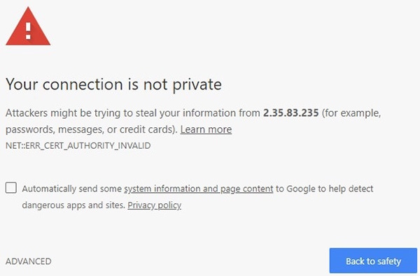
Graphical user interface, text, application, email Description automatically generated
Note: Because cyber crime is on the rise, most modern web browsers are built to alert you to possible threats, such as hacking, spoofing and identity theft. The CURWB Device is connected to the computer using an unsecured connection (in this case, a CAT5/6 cable),; the web browser may display security warnings like the one above. This is normal and expected. During the configuration process, it is safe to ignore these warnings.
6.![]() Click the ADVANCED link. You see the following window:
Click the ADVANCED link. You see the following window:
Figure 120 Security certificate warning (Google Chrome)
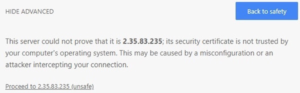
Graphical user interface, text, application, email Description automatically generated
7.![]() Click Proceed to [the URL] (unsafe).
Click Proceed to [the URL] (unsafe).
• The device login window displays:
Figure 121 CURWB device login window
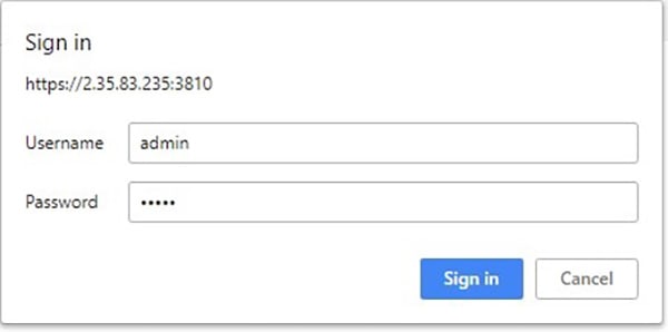
Graphical user interface, text, application, email, Teams Description automatically generated
The factory-set login details are as follows:
8.![]() Enter the correct username and password. Click ' Sign in '.
Enter the correct username and password. Click ' Sign in '.
Initial Configuration with the Device in Provisioning Mode
A few basic configuration settings are required for the CURWB devices to operate. These settings allow the unit to connect to a local network and communicate with the network hardware.
If a new unit is being configured for use for the first time or has been reset to the factory default configuration for any reason, the unit will enter Provisioning Mode. This mode allows you to program the unit's initial configuration settings.
If the unit is in Provisioning Mode, it will try to connect to the internet using Dynamic Host Configuration Protocol (DHCP):
If the unit successfully connects to the Internet, you can do centralized (online) configuration of the unit using the RACER interface.
If the unit fails to connect to the Internet, you can upload a local (offline) configuration of the unit using a.FMCONF file downloaded from the RACER interface.
Note: In Provisioning Mode, the unit connects to the cloud server through a WebSocket connection with 4096-bit asymmetric encryption and verified security certificates, protecting the communication from cyber-security threats.
Check the colored icon to the right of the RACER™ tag in the upper left-hand corner of the screen to verify that the unit is in Provisioning Mode.
RACER status icon (Provisioning Mode)
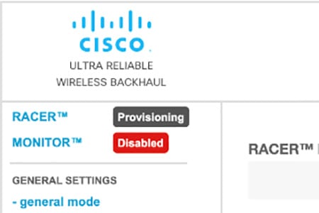
Graphical user interface, text, application Description automatically generated
If the icon reads Provisioning, the unit is in Provisioning Mode. Complete the steps shown in this section to configure the unit.
If the icon reads Online or Offline, the unit has been configured before. In this case, you must choose between two further options:
■![]() If you want to do a new configuration by reverting the unit to Provisioning Mode, reset the device to factory defaults as shown in the CURWB device user manual for that type of device.
If you want to do a new configuration by reverting the unit to Provisioning Mode, reset the device to factory defaults as shown in the CURWB device user manual for that type of device.
■![]() If you want to change the connection settings, but keep the current configuration, change the settings. If the CURWB device is in Provisioning Mode the following RACER™ dialog displays.
If you want to change the connection settings, but keep the current configuration, change the settings. If the CURWB device is in Provisioning Mode the following RACER™ dialog displays.
Figure 122 RACER Management page
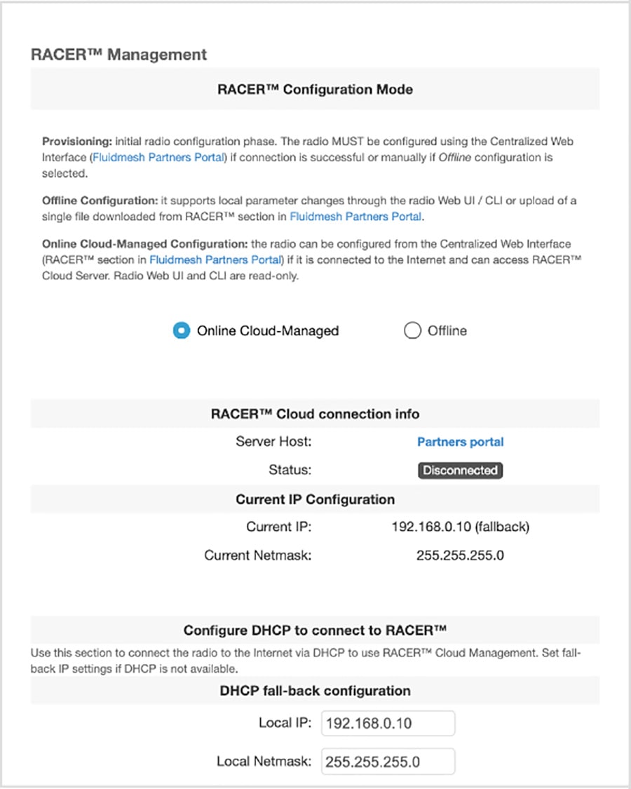
Graphical user interface, text, application Description automatically generated
The unit Local IP address is set to 169.254.a.b, where a and b are the last two parts of the unit's unique unit identification (ID) number. For example, if the unit Mesh ID number is 5.12.34.56, the unit's IP address is set as 169.254.34.56.
The unit can also be reached using the DHCP fallback IP address (192.168.0.10/24).
The unit will attempt to connect to the internet using DHCP.
Note: DHCP is disabled when the unit leaves Provisioning Mode.
Make sure that the CURWB device is connected to a local network that supports DHCP. If the unit connects successfully to the internet and to the Partners Portal, the RACER™ Cloud connection info status is Connected.
Figure 123 RACER™ Cloud connection info status (Connected)
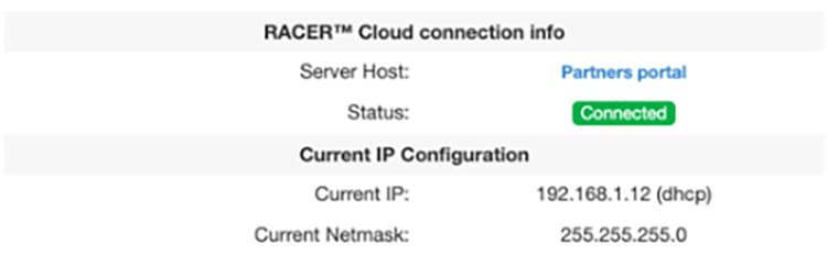
Graphical user interface, application Description automatically generated
Configure the unit using either of the following methods:
■![]() Method1: To do a centralized (online) configuration of the unit using the RACER interface, switch the unit to Online-Cloud Managed mode.
Method1: To do a centralized (online) configuration of the unit using the RACER interface, switch the unit to Online-Cloud Managed mode.
■![]() Method 2: To do a local (offline) configuration of the unit using a.FMCONF file downloaded from the RACER interface, switch the unit to Offline mode.
Method 2: To do a local (offline) configuration of the unit using a.FMCONF file downloaded from the RACER interface, switch the unit to Offline mode.
If the unit connects to the internet in Provisioning Mode, but cannot connect to the CURWB Partners Portal, the unit IP address will automatically be set to 192.168.0.10/24. If the unit cannot connect to the Partners Portal, verify that the Partners Portal can be reached by completing the following steps:
1.![]() Check that the Ethernet cable leading to the unit is properly connected.
Check that the Ethernet cable leading to the unit is properly connected.
2.![]() Check that the local DNS server can resolve a public address.
Check that the local DNS server can resolve a public address.
3.![]() Check that the local DNS server can resolve the IP address of the CURWB Cloud server, and that the address can be reached.
Check that the local DNS server can resolve the IP address of the CURWB Cloud server, and that the address can be reached.
4.![]() Check the network firewall settings. Port 443 must be enabled.
Check the network firewall settings. Port 443 must be enabled.
5.![]() Go to this URL https://partners.fluidmesh.com/
Go to this URL https://partners.fluidmesh.com/
The CURWB Partners Portal page opens in your browser.
If you cannot immediately access the Partners Portal, contact the support desk by sending an e-mail to support@fluidmesh.com.
If the Partners Portal does not come back online, do a local (offline) configuration using a.FMCONF file downloaded from the RACER interface.
If the unit cannot connect to the internet in Provisioning Mode, try to connect to the Internet by completing the following steps:
1.![]() Enter alternative Local IP, Local Netmask, Default Gateway, Local Dns 1 and Local Dns 2 values as needed, using the RACER™ dialog.
Enter alternative Local IP, Local Netmask, Default Gateway, Local Dns 1 and Local Dns 2 values as needed, using the RACER™ dialog.
2.![]() Click the Save fallback IP button.
Click the Save fallback IP button.
The web browser displays the unit reboot dialog.
Figure 124 Unit reboot dialog (typical)
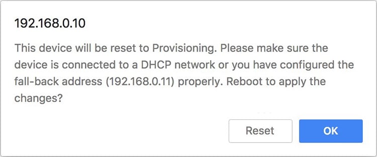
Graphical user interface, text, application Description automatically generated
3.![]() Click the OK button to proceed or click the Reset button to go back to the RACER™ dialog and adjust the settings.
Click the OK button to proceed or click the Reset button to go back to the RACER™ dialog and adjust the settings.
If you click the OK button, the unit will reboot, but will remain in Provisioning Mode.
The unit will attempt to connect to the Internet using the new connection values.
If the unit cannot connect to the Internet using the DHCP fallback configuration settings, the RACER™ Cloud connection info status is shown as Disconnected.
Configure the unit by doing a local (offline) configuration of the unit using a.FMCONF file downloaded from the RACER interface.
Figure 125 RACER™ Cloud connection info status (Disconnected)

For a quick overview of the initial configuration process, refer to the flowchart below. Downloading Device Configuration Files and Firmware from RACER.
A RACER configuration file can be applied to a single device or multiple devices that are not connected to the Internet. The devices can be in the same product line, or different product lines.
An exported configuration file in *.FMCONF format can contain configuration settings for one device or multiple devices, no matter whether the devices are of the same type or different types. Every CURWB device is capable of parsing, recognizing, and acquiring only the relevant settings for its own configuration. When downloading the *.FMCONF file from RACER, the option to include the latest device firmware inside that same file is available.
To apply a configuration file to a non-connected device, complete the following steps:
1.![]() Click the Configure Devices link on the left side of the FM RacerACER interface (below).
Click the Configure Devices link on the left side of the FM RacerACER interface (below).
Figure 126 RACER Configure Devices
Graphical user interface, application Description automatically generated
• The RACER™ Radio Configuration view is shown.
2.![]() Identify the device or devices for download configuration is to be downloaded.
Identify the device or devices for download configuration is to be downloaded.
3.![]() Download the needed configuration, using either of the following methods:
Download the needed configuration, using either of the following methods:
–![]() To download only selected configurations, enable the checkbox to the left of each relevant device listing, and then click the Download selected button (below).
To download only selected configurations, enable the checkbox to the left of each relevant device listing, and then click the Download selected button (below).
Figure 127 RACER Download selected
Graphical user interface, text, application Description automatically generated
4.![]() To download all configurations from all currently listed devices, click the Download All button (below).
To download all configurations from all currently listed devices, click the Download All button (below).
Graphical user interface, application, Teams Description automatically generated
The Download file view displays.
The Download file view presents the option to enable the checkbox for Included latest firmware.
5.![]() Click the blue Download button on the interface to download the file or files.
Click the blue Download button on the interface to download the file or files.
The file or files are downloaded to the chosen download location on your computer as an *.FMCONF file.
CURWB Device Initial Setup and Configuration
The following CURWB configuration steps are described in this section:
■![]() Software and Hardware Prerequisites
Software and Hardware Prerequisites
■![]() Accessing the CURWB Device for Configuration
Accessing the CURWB Device for Configuration
■![]() Initial Configuration with the Device in Provisioning Mode
Initial Configuration with the Device in Provisioning Mode
■![]() Uploading a Device Configuration File from RACER.
Uploading a Device Configuration File from RACER.
This document does not provide a complete configuration guide for CURWB devices and does not cover all possible scenarios where CURWB products may be used. For more information, refer to the CURWB documentation page at the following URL:
https://www.cisco.com/c/en/us/support/wireless/ultra-reliable-wireless-backhaul/series.html
Software and Hardware Prerequisites
To access the Configurator graphical user interface (GUI) and use the Configurator to program the CURWB device you need the following:
A desktop, laptop, or tablet computer equipped with:
■![]() Any current Microsoft Windows, Mac OS, or Linux operating system.
Any current Microsoft Windows, Mac OS, or Linux operating system.
■![]() A CAT5/6 Ethernet cable with an RJ45 connector at one end, and depending on device model, either a M12 X-code connector or a RJ45 connector at the other end.
A CAT5/6 Ethernet cable with an RJ45 connector at one end, and depending on device model, either a M12 X-code connector or a RJ45 connector at the other end.
Accessing the CURWB Device for Configuration
Before the unit can be made part of a wireless network, it must be configured. The on-board Configurator can be used to configure a CURWB device in either of two ways:
■![]() Method 1: By connecting a control device directly to the CURWB device using an Ethernet cable (Local access)
Method 1: By connecting a control device directly to the CURWB device using an Ethernet cable (Local access)
■![]() Method 2: By connecting a control device to the CURWB device through an iInternet connection (Internet access)
Method 2: By connecting a control device to the CURWB device through an iInternet connection (Internet access)
Local Access and Login for Initial Configuration
To use the Configurator interface to access the CURWB device directly, complete the steps that follow:
1.![]() Power ON the unit ON. Wait approximately one minute for the boot sequence to complete.
Power ON the unit ON. Wait approximately one minute for the boot sequence to complete.
2.![]() Connect one end of a CAT5/6 Ethernet cable to the computer that will be used to configure the CURWB device.
Connect one end of a CAT5/6 Ethernet cable to the computer that will be used to configure the CURWB device.
3.![]() Connect the other end of the Ethernet cable to the CURWB device.
Connect the other end of the Ethernet cable to the CURWB device.
4.![]() Manually set the computer's IP address and Netmask to be in the same subnet as the CURWB device. The CURWB device will use the following setting by default and after being factory reset:
Manually set the computer's IP address and Netmask to be in the same subnet as the CURWB device. The CURWB device will use the following setting by default and after being factory reset:
5.![]() Launch the computer web browser.
Launch the computer web browser.
6.![]() Enter the IP address of the CURWB device in the browser URL entry field.
Enter the IP address of the CURWB device in the browser URL entry field.
If the Configurator interface displays immediately, proceed to step 9 below.
Alternatively, you may see the following window displays:
Figure 129 'Connection Not Private' warning (Google Chrome)
Graphical user interface, text, application, email Description automatically generated
Note: Because cyber crime is on the rise, most modern web browsers are built to alert you to possible threats, such as hacking, spoofing and identity theft.
The CURWB Device is connected to the computer using an unsecured connection (in this case, a CAT5/6 cable),; the web browser may display security warnings like the one above. This is normal and expected. During the configuration process, it is safe to ignore these warnings.
7.![]() Click the ADVANCED link. • You will see the following window:
Click the ADVANCED link. • You will see the following window:
Figure 130 Security certificate warning (Google Chrome)
Graphical user interface, text, application, email Description automatically generated
8.![]() Click Proceed to [the URL] (unsafe). • The device login window displays:
Click Proceed to [the URL] (unsafe). • The device login window displays:
Figure 131 CURWB device login window
Graphical user interface, text, application, email, Teams Description automatically generated
The factory-set login details are as follows:
9.![]() Enter the correct username and password. Click 'EnterSign in'. The Configurator GUI of the CURWB Device displays.
Enter the correct username and password. Click 'EnterSign in'. The Configurator GUI of the CURWB Device displays.
Initial Configuration with the Device in Provisioning Mode
A few basic configuration settings Tare required for the CURWB devices cannot be operated without entering to operate. some basic configuration settings. These settings allow the unit to connect to a local network and communicate with the network hardware.
If a new unit is being configured for use for the first time or has been reset to the factory default configuration for any reason, the unit will enter Provisioning Mode. This mode allows you to program the unit's initial configuration settings.
If the unit is in Provisioning Mode, it will try to connect to the internet using Dynamic Host Configuration Protocol (DHCP):
If the unit successfully connects to the internet, you can do centralized (online) configuration of the unit using the RACER interface.
If the unit fails to connect to the internet, you can upload a local (offline) configuration of the unit using a.FMCONF file downloaded from the RACER interface.
Note: In Provisioning Mode, the unit connects to the cloud server through a WebSocket connection with 4 096-bit asymmetric encryption and verified security certificates, protecting the communication from cyber-security threats.
Check the colored icon to the right of the RACER™ tag in the upper left-hand corner of the screen to verify that the unit is in Provisioning Mode. by looking at the colored icon to the right of the RACER™ tag in the upper left-hand corner of the screen.
Figure 132 RACER status icon (Provisioning Mode - 387551)
Graphical user interface, text, application Description automatically generated
If the icon reads Provisioning, the unit is in Provisioning Mode. Complete the steps shown in this section to configure the unit.
1.![]() If the icon reads Online or Offline, the unit has been configured before. In this case, you must choose between two further options:
If the icon reads Online or Offline, the unit has been configured before. In this case, you must choose between two further options:
■![]() If you want to do a new configuration by reverting the unit to Provisioning Mode, reset the device to factory defaults as shown in the CURWB device user manual for that type of device.
If you want to do a new configuration by reverting the unit to Provisioning Mode, reset the device to factory defaults as shown in the CURWB device user manual for that type of device.
■![]() If you want to change the connection settings, but keep the current configuration, change the settings.
If you want to change the connection settings, but keep the current configuration, change the settings.
If the CURWB device is in Provisioning Mode the RACER™ dialog displays.
Figure 133 RACER Management page
Graphical user interface, text, application Description automatically generated
The Local IP address is set to 169.254.a.b, where a and b are the last two parts of the unique unit identification (ID) number. For example, if the unit Mesh ID number is 5.12.34.56, the IP address is set as 169.254.34.56.
The unit can also be reached using the DHCP fallback IP address (192.168.0.10/24).
The unit will attempt to connect to the internet using DHCP.
Note: DHCP is disabled when the unit leaves Provisioning Mode.
Make sure that the CURWB device is connected to a local network that supports DHCP. If the unit connects successfully to the internet and to the Partners Portal, the RACER™ Cloud connection info status will be shown as Connected.
Figure 134 RACER™ Cloud connection info status (Connected)
Graphical user interface, application Description automatically generated
Configure the unit using either of the following methods:
■![]() Method1: To do a centralized (online) configuration of the unit using the RACER interface, switch the unit to Online-Cloud Managed mode.
Method1: To do a centralized (online) configuration of the unit using the RACER interface, switch the unit to Online-Cloud Managed mode.
■![]() Method 2: To do a local (offline) configuration of the unit using a.FMCONF file downloaded from the RACER interface, switch the unit to Offline mode.
Method 2: To do a local (offline) configuration of the unit using a.FMCONF file downloaded from the RACER interface, switch the unit to Offline mode.
If the unit connects to the internet in Provisioning Mode, but cannot connect to the CURWB Partners Portal, the unit’s IP address will automatically be set to 192.168.0.10/24. If the unit cannot connect to the Partners Portal, verify that the Partners Portal can be reached by completing the following steps:
1.![]() Check that the Ethernet cable leading to the unit is properly connected.
Check that the Ethernet cable leading to the unit is properly connected.
2.![]() Check that the local DNS server can resolve a public address.
Check that the local DNS server can resolve a public address.
3.![]() Check that the local DNS server can resolve the IP address of the CURWB Cloud server, and that the address can be reached.
Check that the local DNS server can resolve the IP address of the CURWB Cloud server, and that the address can be reached.
4.![]() Check the network firewall settings. Port 443 must be enabled.
Check the network firewall settings. Port 443 must be enabled.
5.![]() Go to this URL https://partners.fluidmesh.com/
Go to this URL https://partners.fluidmesh.com/
• The CURWB Partners Portal page should opens in your browser.
If you cannot immediately access the Partners Portal, contact the support desk by sending an e-mail to support@fluidmesh.com.
If the Partners Portal does not come back online, do a local (offline) configuration using a.FMCONF file downloaded from the RACER interface.
If the unit cannot connect to the internet in Provisioning Mode, try to connect to the Internet by completing the following steps:
1.![]() Enter alternative Local IP, Local Netmask, Default Gateway, Local Dns 1 and Local Dns 2 values as needed, using the RACER™ dialog.
Enter alternative Local IP, Local Netmask, Default Gateway, Local Dns 1 and Local Dns 2 values as needed, using the RACER™ dialog.
2.![]() Click the Save fallback IP button. The web browser displays the unit reboot dialog.
Click the Save fallback IP button. The web browser displays the unit reboot dialog.
Figure 135 Unit reboot dialog (typical)
Graphical user interface, text, application Description automatically generated
3.![]() Click the OK button to proceed or click the Reset button to go back to the RACER™ dialog and adjust the settings.
Click the OK button to proceed or click the Reset button to go back to the RACER™ dialog and adjust the settings.
If you click the OK button, the unit will reboot, but will remain in Provisioning Mode.
The unit will attempt to connect to the Internet using the new connection values.
If the unit cannot connect to the Internet using the DHCP fallback configuration settings, the RACER™ Cloud connection info status is shown as Disconnected.
Configure the unit by doing a local (offline) configuration of the unit using a.FMCONF file downloaded from the RACER interface.
Figure 136 RACER™ Cloud connection info status (Disconnected)
For a quick overview of the initial configuration process, refer to the flowchart below.
Downloading Device Configuration Files and Firmware from RACER
A RACER configuration file can be applied to a single device or multiple devices that are not connected to the Internet. The devices can be in the same product line, or different product lines.
An exported configuration file in *.FMCONF format can contain configuration settings for one device or multiple devices, of the same device type/category. Every CURWB device is capable of parsing, recognizing, and acquiring only the relevant settings for its own configuration. When downloading the *.FMCONF file from RACER, the option to include the latest device firmware inside that same file is available.
To apply a configuration file to a non-connected device, complete the following steps:
1.![]() Click the Configure Devices link on the left side of the FM RACER interface (below).
Click the Configure Devices link on the left side of the FM RACER interface (below).
Figure 137 RACER Configure Devices
Graphical user interface, application Description automatically generated
• The RACER™ Radio Configuration view is shown.
2.![]() Identify the device or devices for download configuration.
Identify the device or devices for download configuration.
Download the needed configuration, using either of the following methods:
■![]() To download only selected configurations, enable the checkbox to the left of each relevant device listing, and then click the Download selected button (below).
To download only selected configurations, enable the checkbox to the left of each relevant device listing, and then click the Download selected button (below).
Figure 138 RACER Download selected
Graphical user interface, text, application Description automatically generated
■![]() To download all configurations from all currently listed devices, click the Download All button (below).
To download all configurations from all currently listed devices, click the Download All button (below).
Graphical user interface, application, Teams Description automatically generated The Download file view displays.
The Download file view presents the option to enable the checkbox for Included latest firmware can be checked.
Click the blue Download button on the interface to download the file or files.
The file or files are downloaded to the chosen download location on your computer as an *.FMCONF file.
CURWB Device Initial Setup and Configuration
The following CURWB configuration steps are described in this section:
■![]() Software and Hardware Prerequisites
Software and Hardware Prerequisites
■![]() Accessing the CURWB Device for Configuration
Accessing the CURWB Device for Configuration
■![]() Local Access and Login for Initial Configuration
Local Access and Login for Initial Configuration
■![]() Switching between Offline and Online Modes
Switching between Offline and Online Modes
■![]() Uploading a Device Configuration File from RACER
Uploading a Device Configuration File from RACER
This document does not provide a complete configuration guide for CURWB devices and does not cover all possible scenarios where CURWB products may be used. For more information, refer to the CURWB documentation page at the following URL:
https://www.cisco.com/c/en/us/support/wireless/ultra-reliable-wireless-backhaul/series.html
Software and Hardware Prerequisites
To access the Configurator graphical user interface (GUI) and use the Configurator to program the CURWB device you need the following:
A desktop, laptop, or tablet computer equipped with:
■![]() Any current Microsoft Windows, Mac OS, or Linux operating system.
Any current Microsoft Windows, Mac OS, or Linux operating system.
■![]() An integrated Ethernet port or an external USB Ethernet adapter.
An integrated Ethernet port or an external USB Ethernet adapter.
■![]() A CAT5/6 Ethernet cable with an RJ45 connector at one end, and depending on device model, either a M12 X-code connector or a RJ45 connector at the other end.
A CAT5/6 Ethernet cable with an RJ45 connector at one end, and depending on device model, either a M12 X-code connector or a RJ45 connector at the other end.
Accessing the CURWB Device for Configuration
Before the unit can be made part of a wireless network, it must be configured.
The on-board Configurator can be used to configure a CURWB device in either of two ways:
■![]() Method 1: By connecting a control device directly to the CURWB device using an Ethernet cable (Local access)
Method 1: By connecting a control device directly to the CURWB device using an Ethernet cable (Local access)
■![]() Method 2: By connecting a control device to the CURWB device through an Internet connection (Internet access)
Method 2: By connecting a control device to the CURWB device through an Internet connection (Internet access)
Local Access and Login for Initial Configuration
To use the Configurator interface to access the CURWB device directly, complete the steps that follow:
1.![]() Power the unit ON. Wait approximately one minute for the boot sequence to complete.
Power the unit ON. Wait approximately one minute for the boot sequence to complete.
2.![]() Connect one end of a CAT5/6 Ethernet cable to the computer that will be used to configure the CURWB device.
Connect one end of a CAT5/6 Ethernet cable to the computer that will be used to configure the CURWB device.
3.![]() Connect the other end of the Ethernet cable to the CURWB device.
Connect the other end of the Ethernet cable to the CURWB device.
4.![]() Manually set the computer's IP address and Netmask to be in the same subnet as the CURWB device. The CURWB device will use the following setting by default and after being factory reset:
Manually set the computer's IP address and Netmask to be in the same subnet as the CURWB device. The CURWB device will use the following setting by default and after being factory reset:
5.![]() Launch the computer's web browser.
Launch the computer's web browser.
6.![]() Enter the IP address of the CURWB device in the browser's URL entry field.
Enter the IP address of the CURWB device in the browser's URL entry field.
If the Configurator interface is shown displays immediately, proceed to step 9 below.
Alternatively, you may see the following window displays:
Figure 140 'Connection Not Private' warning (Google Chrome)
Graphical user interface, text, application, email Description automatically generated
Note: Because cyber crime is on the rise, most modern web browsers are built to alert you to possible threats, such as hacking, spoofing and identity theft.
The CURWB Device is connected to the computer using an unsecured connection (in this case, a CAT5/6 cable),; the web browser may display security warnings like the one above. This is normal and expected. During the configuration process, it is safe to ignore these warnings.
7.![]() Click the ADVANCED link. • You will see the following window:
Click the ADVANCED link. • You will see the following window:
Figure 141 Security certificate warning (Google Chrome)
Graphical user interface, text, application, email Description automatically generated
8.![]() Click Proceed to [the URL] (unsafe). • The device login window will be displays:
Click Proceed to [the URL] (unsafe). • The device login window will be displays:
Figure 142 CURWB device login window
Graphical user interface, text, application, email, Teams Description automatically generated
The factory-set login details are as follows:
Initial Configuration with the Device in Provisioning Mode
A few basic configuration settings Tare required for the CURWB devices cannot be operated without entering to operate. some basic configuration settings. These settings allow the unit to connect to a local network and communicate with the network hardware.
If a new unit is being configured for use for the first time or has been reset to the factory default configuration for any reason, the unit will enter Provisioning Mode. This mode allows you to program the unit's initial configuration settings.
If the unit is in Provisioning Mode, it will try to connect to the internet using Dynamic Host Configuration Protocol (DHCP):
If the unit successfully connects to the internet, you can do centralized (online) configuration of the unit using the RACER interface.
If the unit fails to connect to the internet, you can upload a local (offline) configuration of the unit using a.FMCONF file downloaded from the RACER interface.
Note: In Provisioning Mode, the unit connects to the cloud server through a WebSocket connection with 4 096-bit asymmetric encryption and verified security certificates, protecting the communication from cyber-security threats.
Check the colored icon to the right of the RACER™ tag in the upper left-hand corner of the screen to verify that the unit is in Provisioning Mode. by looking at the colored icon to the right of the RACER™ tag in the upper left-hand corner of the screen.
Figure 143 RACER status icon (Provisioning Mode)
Graphical user interface, text, application Description automatically generated
If the icon reads Provisioning, the unit is in Provisioning Mode. Complete the steps shown in this section to configure the unit. by doing the steps shown in this section.
If the icon reads Online or Offline, the unit has been configured before. In this case, you must choose between two further can choose:
■![]() If you want to do a new configuration by reverting the unit to Provisioning Mode, reset the device to factory defaults as shown in the CURWB device user manual for that type of device.
If you want to do a new configuration by reverting the unit to Provisioning Mode, reset the device to factory defaults as shown in the CURWB device user manual for that type of device.
■![]() If you want to change the connection settings, but keep the current configuration, change the settings.
If you want to change the connection settings, but keep the current configuration, change the settings.
If the CURWB device is in Provisioning Mode: The RACER™ dialog displays.
Figure 144 RACER Management page
Graphical user interface, text, application Description automatically generated
The Local IP address will is set to 169.254.a.b, where a and b are the last two parts of the unique unit identification (ID) number. For example, if the unit Mesh ID number is 5.12.34.56, the IP address is set as 169.254.34.56.
The unit can also be reached using the DHCP fallback IP address (192.168.0.10/24).
The unit will attempt to connect to the internet using DHCP.
Note: DHCP is disabled when the unit leaves Provisioning Mode.
Make sure that the CURWB device is connected to a local network that supports DHCP. If the unit connects successfully to the internet and to the Partners Portal, the RACER™ Cloud connection info status will be shown as Connected.
Figure 145 RACER™ Cloud connection info status (Connected)
Graphical user interface, application Description automatically generated
Configure the unit using either of the following methods:
■![]() Method1: To do a centralized (online) configuration of the unit using the RACER interface, switch the unit to Online-Cloud Managed mode.
Method1: To do a centralized (online) configuration of the unit using the RACER interface, switch the unit to Online-Cloud Managed mode.
■![]() Method 2: To do a local (offline) configuration of the unit using a.FMCONF file downloaded from the RACER interface, switch the unit to Offline mode.
Method 2: To do a local (offline) configuration of the unit using a.FMCONF file downloaded from the RACER interface, switch the unit to Offline mode.
If the unit connects to the internet in Provisioning Mode, but cannot connect to the CURWB Partners Portal, the unit’s IP address will automatically be set to 192.168.0.10/24. If the unit cannot connect to the Partners Portal, verify that the Partners Portal can be reached by completing the following steps:
1.![]() Check that the Ethernet cable leading to the unit is properly connected.
Check that the Ethernet cable leading to the unit is properly connected.
2.![]() Check that the local DNS server can resolve a public address.
Check that the local DNS server can resolve a public address.
3.![]() Check that the local DNS server can resolve the IP address of the CURWB Cloud server, and that the address can be reached.
Check that the local DNS server can resolve the IP address of the CURWB Cloud server, and that the address can be reached.
4.![]() Check the network firewall settings. Port 443 must be enabled.
Check the network firewall settings. Port 443 must be enabled.
Go to this URL https://partners.fluidmesh.com/
• The CURWB Partners Portal page should opens in your browser.
If you cannot immediately access the Partners Portal cannot be accessed, contact the support desk by sending an e-mail to support@fluidmesh.com.
If the Partners Portal does not come back online, do a local (offline) configuration using a.FMCONF file downloaded from the RACER interface.
If the unit cannot connect to the internet in Provisioning Mode, try to connect to the iInternet by doingcompleting the following steps:
Enter alternative Local IP, Local Netmask, Default Gateway, Local Dns 1 and Local Dns 2 values as needed, using the RACER™ dialog.
Click the Save fallback IP button.
The web browser displays the unit reboot dialog.
Figure 146 Unit reboot dialog (typical)
Graphical user interface, text, application Description automatically generated
Click the OK button to proceed or click the Reset button to go back to the RACER™ dialog and adjust the settings.
If you click the OK button, the unit will reboot, but will remain in Provisioning Mode.
The unit will attempt to connect to the i Internet using the new connection values.
If the unit cannot connect to the i Internet using the DHCP fallback configuration settings, the RACER™ Cloud connection info status will is shown as Disconnected.
Configure the unit by doing a local (offline) configuration of the unit using a.FMCONF file downloaded from the RACER interface.
Figure 147 RACER™ Cloud connection info status (Disconnected)
For a quick overview of the initial configuration process, refer to the flowchart below.
Figure 148 CURWB Device Provisioning Flowchart
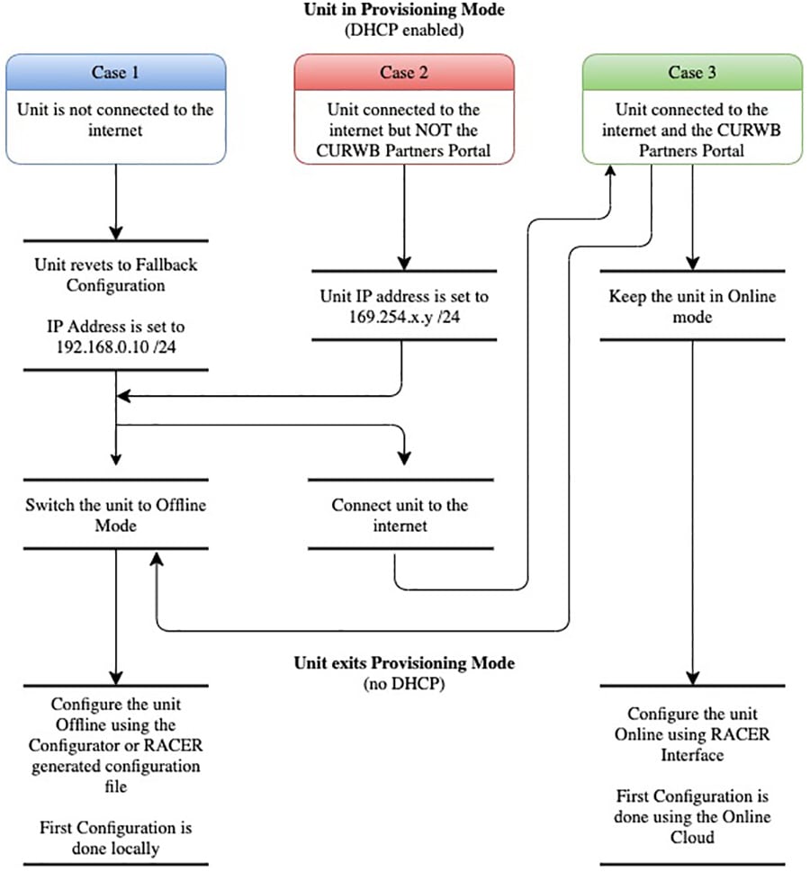
Switching between Offline and Online Modes
The Configurator interface may not be in the required mode for configuration when you log in.
To do a centralized (online) configuration of the unit using the RACER interface, switch the unit to Online-Cloud Managed mode.
To do a local (offline) configuration of the unit using a.FMCONF file downloaded from the RACER interface, switch the unit to Offline mode.
To switch between Online-Cloud Managed and Offline modes, complete these steps:
1.![]() Log in to the Configurator interface as shown in Local Access and Login for Initial Configuration.
Log in to the Configurator interface as shown in Local Access and Login for Initial Configuration.
2.![]() Click the RACER™ link in the left-hand settings menu.
Click the RACER™ link in the left-hand settings menu.
3.![]() The Configurator landing page will be displays.
The Configurator landing page will be displays.
Figure 149 CURWB Configurator RACER Page
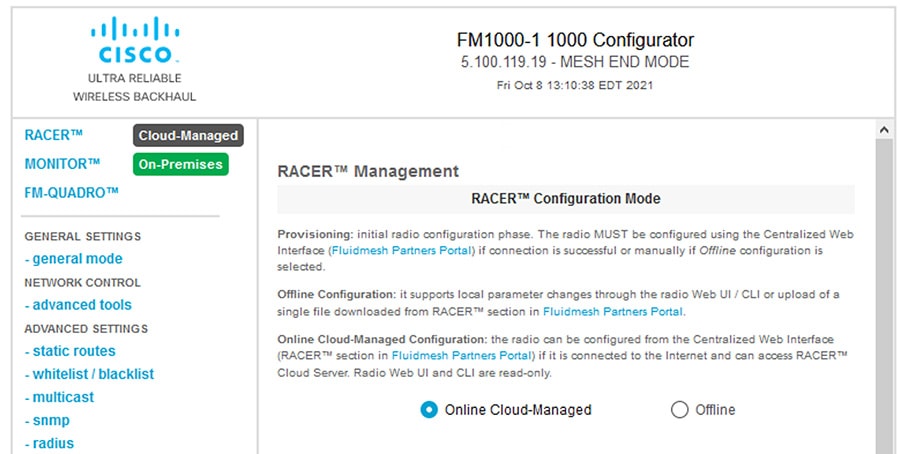
Graphical user interface, text, application, email Description automatically generated
The lower section of the RACER™ Configuration Mode page has two radio buttons that show whether the unit is in Online Cloud-Managed mode, or Offline mode.
4.![]() If the unit is not in the correct mode, click the Online Cloud-Managed or Enable the appropriate radio button as needed.
If the unit is not in the correct mode, click the Online Cloud-Managed or Enable the appropriate radio button as needed.
A confirmation dialog displays, asking if you want to switch the unit prompting you for verification of the chosen mode.
5.![]() To switch the radio to the chosen mode, click the Confirm button to continue.
To switch the radio to the chosen mode, click the Confirm button to continue.
A ten-second countdown displays. The Configurator interface web page reloads. The unit is switched to the chosen configuration mode.
Uploading a Device Configuration File from RACER.
Using RACER Online Cloud-Managed mode:
A configuration file that has been created using the RACER interface must be uploaded to the unit. To upload a RACER configuration file, do the following steps:
1.![]() Switch the unit to Offline mode as shown in section Switching between Offline and Online Modes.
Switch the unit to Offline mode as shown in section Switching between Offline and Online Modes.
2.![]() Click the RACER™ link in the left-hand settings menu.
Click the RACER™ link in the left-hand settings menu.
3.![]() The Configurator landing page displays.
The Configurator landing page displays.
4.![]() Click the Browse button in the Upload Configuration File section.
Click the Browse button in the Upload Configuration File section.
Figure 150 Figure 18 Configurator interface - (FM Racer configuration file upload dialog)
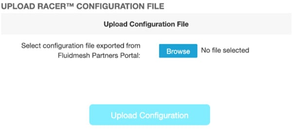
Graphical user interface, text, application, chat or text message description automatically generated
5.![]() Find and choose the correct configuration file. Follow the software prompts to select the correct configuration file.
Find and choose the correct configuration file. Follow the software prompts to select the correct configuration file.
6.![]() Click the Upload Configuration button. The configuration file is uploaded to the unit.
Click the Upload Configuration button. The configuration file is uploaded to the unit.
7.![]() Click the Apply button. The device will reboots with the applied configuration.
Click the Apply button. The device will reboots with the applied configuration.
Appendix A: RACER Configuration Template Table
Create a template for each one of these types of devices:
■![]() Vehicle Mobile Radio – Single Frequency
Vehicle Mobile Radio – Single Frequency
■![]() Vehicle Mobile Radio - Multi-Frequency
Vehicle Mobile Radio - Multi-Frequency
After the templates are created, they can be assigned to a project and then applied to a device.
This table contains the configuration settings that are recommended to be used when creating the templates. If a cell is blank, then that parameter does not apply to that type of device. For cells that state “Device Specific” then that parameter is device specific and must be entered after applying the template to the device. There are times when device specific parameters might be entered into a template if every device in that group uses the same configuration.
| [1] for the device to reach the RACER online portal DNS is required |
|||||||
 Feedback