Cisco M SFS7000E Installation Note: InfiniBand Blade Switch for the Dell Modular Server Chassis
Available Languages
Table Of Contents
Cisco M SFS7000E Installation Note:
InfiniBand Blade Switch for the Dell Modular Server ChassisI/O Module Bays and HCA Expansion Cards
Installing the Cisco M SFS7000E InfiniBand Switch
Removing the Cisco M SFS7000E InfiniBand Switch
External Network Management Requirements
Statement 1071—Warning Definition
Obtaining Documentation, Obtaining Support, and Security Guidelines
Cisco M SFS7000E Installation Note:
InfiniBand Blade Switch for the Dell Modular Server Chassis
This document provides instructions on how to install the Cisco M SFS7000E InfiniBand Switch in the Dell Modular Server Chassis. The Dell Modular Server Chassis is a system that supports up to sixteen server modules and up to four InfiniBand switches. You may install the InfiniBand switch in one of four chassis I/O module bays on the rear panel of the server chassis.

Note
There are six chassis I/O module bays on the rear panel of the server chassis. The InfiniBand switches are supported in the middle four bays that are connected to Fabrics B and C.
For details about the number, types, and location of the module bays and for additional information about the entire modular server system, see the documentation for the Dell PowerEdge Servers at www.support.dell.com.
Contents
This publication includes the following sections:
•
•
•
•
•
Safety Overview
Safety warnings appear throughout this publication in procedures that, if performed incorrectly, may harm you. A warning symbol precedes each warning statement.

Warning
Warning
Warning
Warning
Warning
Warning
Warning
Warning
Warning
Parts List
This section describes the parts list. The Cisco M SFS7000E InfiniBand Switch package includes the following parts:
•
•
•
InfiniBand Blade Switch for the Dell Modular Server Chassis•
Switch Description
This section describes the Cisco M SFS7000E InfiniBand Switch.
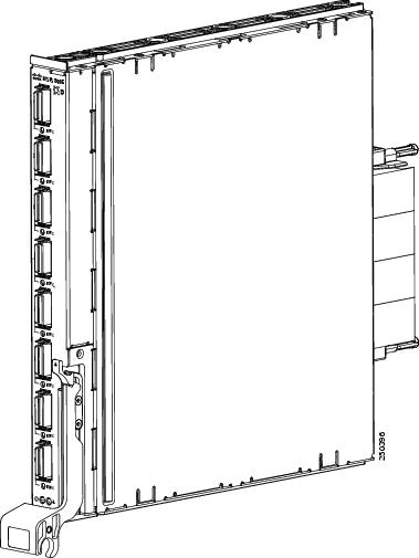
The Cisco M SFS7000E InfiniBand Switch (see Figure 1) connects to the mid-plane of the Dell Modular Server Chassis and provides user-accessible rear-plane ports. The blade switches are installed in the system I/O module bays in the rear of the chassis. Each switch has sixteen 4x ports facing the mid-plane and eight 4x ports facing the exterior of the chassis. These ports drive Cisco- or Dell-approved DDR IB cables.
Figure 1 Cisco M SFS7000E InfiniBand Switch
I/O Module Bays and HCA Expansion Cards
Within the Dell Modular Server Chassis unit, blade switches manage traffic to and from up to two HCA IB mezzanine cards on the hosts. Each HCA IB mezzanine card adds two IB ports to a host. Each HCA port connects through the unit mid-plane to a particular blade switch slot. The IB ports of the HCA card that is seated in the HCA B location, connect to I/O module bays B1 and B2. The IB ports of the HCA card that is seated in the HCA C location, connect to I/O module bays C1 and C2. See Figure 2 and Table 1 for the location of the HCA cards and the corresponding I/O module bays.
For more details about the location of the HCA IB mezzanine card slots in the Dell Server Blade, see the Dell PowerEdge M600 and M605 Hardware Owners Manual.
.
Figure 2 HCA Mezzanine Card Ports and Corresponding Switch I/O Module Bays

Table 1 HCA Mezzanine Card Ports and Corresponding Switch I/O Module Bays
B
1
B1
2
B2
C
1
C1
2
C2
Pre-installation Guidelines
This section describes some pre-installation guidelines. Before you begin installation, complete the following procedures:
•
•
•
Note
Installing the Cisco M SFS7000E InfiniBand Switch
This section describes how to install the Cisco M SFS7000E InfiniBand Switch.
The Cisco M SFS7000E InfiniBand Switch can be hot-swapped while the Dell 10G system (PowerEdge) is online. When you install a switch, you do not need to power down the server chassis.
The Cisco M SFS7000E InfiniBand Switch fits into four different bays on the Dell Modular Server Chassis. These bays connect to either fabric B or C. Each one of these fabrics connects to a mezzanine card on each of the 16 server modules. The HCA is designed to reside in these mezzanine connectors. Two switches may be used for each fabric in a non-blocking configuration. Multiple fabrics may be used simultaneously for increased bandwidth.
Note
To install the Cisco M SFS7000E InfiniBand Switch in the Dell Modular Server Chassis, perform the following steps:
Step 1
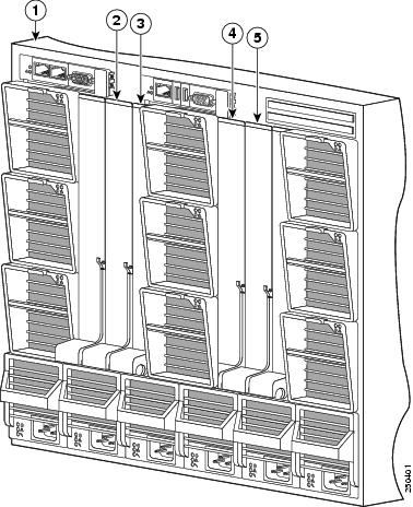
If the HCA IB mezzanine card B is installed, you may install the Cisco M SFS7000E InfiniBand Switch in I/O slots B1 and/or B2. If the HCA IB mezzanine card C is installed, you may install the Cisco M SFS7000E InfiniBand Switch in I/O slots C1 and/or C2.
Figure 3 Chassis I/O Module Bays
Step 2
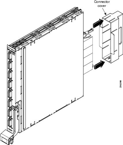
Step 3
Figure 4 Removing the Connector Cover
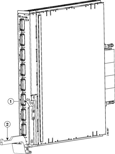
Step 4
Figure 5 Switch Handle in Open Position
Step 5
Figure 6 shows the switch being inserted into the server chassis and the direction in which to rotate the switch handle to secure it.
Figure 6 Inserting the Switch into the Server Chassis

Removing the Cisco M SFS7000E InfiniBand Switch
To remove the Cisco M SFS7000E InfiniBand Switch, perform the following steps:
Step 1
Step 2
Step 3
Step 4
Step 5
Note
Connecting InfiniBand Cables
This section describes briefly how to connect your IB cables.
Use IB cables to connect your Cisco M SFS7000E InfiniBand Switch. To plug in an IB cable, push the connector into the interface. For the pull connector, push the latch until it is engaged after it is in the interface. An alternative method to plug in a pull connector IB cable is to push the latch first, and then insert the connector until you hear a click. (See Figure 7 and Figure 8.)
Figure 7 InfiniBand Cable with Pinch Connector
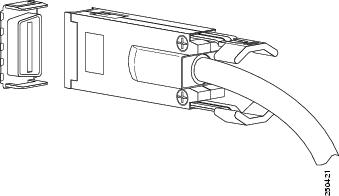
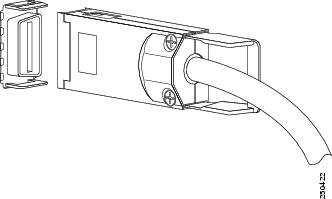
Figure 8 InfiniBand Cable with Pull Connector
Note
To remove a cable with a pinch connector, pinch both sides of the back of the connector, as shown in Figure 9, and pull the connector away from the port.
Figure 9 Removing Cable with a Pinch Connector

To remove a cable with a pull connector, grasp the connector with one hand and push it toward the port, and then pull the latch away from the port with your other hand while gently wiggling the connector away from the port, as shown in Figure 10.
Figure 10 Removing Cable with a Pull Connector

Note
External LED Specifications
This section describes the external LED specifications for the Cisco M SFS7000E InfiniBand Switch.
Figure 11 LED Indicators on Switch
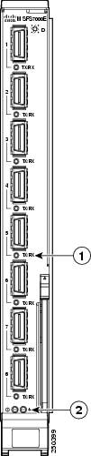
InfiniBand Port Status LEDs
A port status LED indicator (green) exists next to each IB port on the Cisco M SFS7000E InfiniBand Switch, as shown in Figure 11. Table 2 describes IB port status LED indicators. The eight ports on the IB switch module are numbered next to each LED indicator.
Table 2 InfiniBand Port Status LED Indicators
On (solid)
Logical link exists
Blinking
Traffic active
Off
Link error or Subnet Manager is not running
Switch Status LEDs
Each IB switch module includes two LEDs (one green and one bi-color, blue and amber), as shown in Figure 11. The power LED and the system status LED provide the overall system status for the Cisco M SFS7000E InfiniBand Switch and are controlled by the Dell Remote Access Controller/Modular Chassis (DRAC/MC) management board. The DRAC/MC checks whether or not the switch blade is valid and has correct identifiers. Table 3 describes the green-colored power LED indicator. Table 4 describes the bi-colored system status LED indicator.
External Network Management Requirements
You can manage the Cisco M SFS7000E InfiniBand Switch in an InfiniBand network by using the Cisco High-Performance Subnet Manager or the Cisco Embedded Subnet Manager.
Warning Translation
This section repeats, in multiple languages, the basic warning appropriate for the
Cisco M SFS7000E InfiniBand Switch. See the Regulatory Compliance and Safety Information for the Cisco M SFS7000E InfiniBand Blade Switch for the Dell Modular Server Chassis document for translations of all warning messages associated with this switch.Statement 1071—Warning Definition
Related Documentation
For additional information related to the Cisco M SFS7000E InfiniBand Switch, see the following documents:
•
•
•
Obtaining Documentation, Obtaining Support, and Security Guidelines
For information on obtaining documentation, obtaining support, providing documentation feedback, security guidelines, and also recommended aliases and general Cisco documents, see the monthly What's New in Cisco Product Documentation, which also lists all new and revised Cisco technical documentation, at:
http://www.cisco.com/en/US/docs/general/whatsnew/whatsnew.html
This document is to be used in conjunction with the documents listed in the "Related Documentation" section.
Any Internet Protocol (IP) addresses used in this document are not intended to be actual addresses. Any examples, command display output, and figures included in the document are shown for illustrative purposes only. Any use of actual IP addresses in illustrative content is unintentional and coincidental.
© 2007 Cisco Systems, Inc. All rights reserved.
Printed in the USA on recycled paper containing 10% postconsumer waste.


 Feedback
Contact Cisco
- Open a Support Case

- (Requires a Cisco Service Contract)