Table Of Contents
Booting from a Fibre Channel SAN
Checking the HCA Firmware Version
Configuring a Fibre Channel Connection
Using Element Manager and a Host with a Remote Boot HCA
Using the CLI and a Host with a Remote Boot HCA
Installing an Image on Fibre Channel Storage
Configuring and Booting an Image
Booting from a Fibre Channel SAN
The following sections appear in this chapter:
•Checking the HCA Firmware Version
•Configuring a Fibre Channel Connection
•Pre-Installation Requirements
•Installing an Image on Fibre Channel Storage
•Configuring and Booting an Image
Overview
To perform a SAN boot with the Boot over IB feature (BoIB-SAN), you must perform the following high-level steps:
Step 1 Install and connect all required hardware.
For more information, see the "Installing Hardware" section.
Step 2 Load the correct firmware onto the HCA.
You can upgrade standard and low-profile HCAs to run BoIB-capable firmware. To upgrade the firmware on your HCA, refer to the Cisco SFS Host Drivers User Guide for Windows.
Note Skip this step if your HCA already runs BoIB firmware. To determine if your HCA already runs the appropriate software, see the "Checking the HCA Firmware Version" section.
Step 3 Configure an ITL group to connect your host to the Fibre Channel storage.
For more information, see the "Configuring and Booting an Image" section.
Note Skip this step if your environment runs VFrame software. VFrame Director, along with a server switch and gateways, creates a programmable switching fabric for mapping servers to storage and networking resources. For more information, see the Cisco VFrame InfiniBand Director User Guide.
Step 4 Load an image onto a Fibre Channel storage device.
For more information, see the "Configuring a Fibre Channel Connection" section.
Note Skip this step if an image already resides on your storage.
Step 5 Boot the remote image.
Step 6 For more information, see the "Configuring and Booting an Image" section.
Setting up Hardware
A SAN boot with the BoIB feature uses the following hardware:
•A host with an HCA
•A server switch with a Fibre Channel gateway
•A Fibre Channel storage device (connected, optionally, through a SAN switch or switch fabric)
•(Optional) A portable CD ROM drive for servers without a local drive
•(Optional) A KVM device, recommended to view the installation process
Installing Hardware
To create the physical environment for your SAN boot, perform the following high-level steps:
Step 1 Install the HCA into your host.
For details, refer to the Cisco SFS InfiniBand Host Drivers User Guide for Windows.
Step 2 Connect the HCA IB port to the IB fabric.
Step 3 Install the Fibre Channel gateway into your server switch.
For details, refer to the Cisco SFS InfiniBand Fibre Channel Gateway User Guide.
Step 4 Connect the Fibre Channel gateway to a Fibre Channel storage device or to a SAN fabric with a Fibre Channel storage device.
Checking the HCA Firmware Version
This section describes how to check the HCA firmware version. To verify that your HCA provides the BoIB feature, enter the /user/local/topspin/sbin/tvflash-i command from the host CLI. If ".Boot" appears in the description of your HCA, the HCA includes the BoIB feature.
If your HCA does not run BoIB firmware, update the HCA. For instructions, see the Cisco SFS InfiniBand Host Drivers User Guide for Windows.
The following example shows how to check the HCA firmware version:
C:\Program Files\Topspin\util>tvflash -iHCA #0: MT25208, Tavor Compat, Lion Cub, revision A0 (firmware autoupgrade)Primary image is v4.7.600 build 3.2.0.118, with label 'HCA.LionCub.RevC.A0'Secondary image is v4.8.200 build 3.2.0.133, with label 'HCA.LionCub.RevC.A0'Vital Product DataProduct Name: Lion cubP/N: MHEL-CF128-TCE/C: C2S/N: MT0602X00642Freq/Power: PCIe x8Checksum: OkDate Code: N/AC:\Program Files\Topspin\util>
Note The firmware is available on the BoIB ISO image. For instructions about how to upgrade your firmware, see the Cisco SFS InfiniBand Host Drivers User Guide for Windows.
Configuring a Fibre Channel Connection
This section describes how to configure a Fibre Channel connection and includes the following topics:
•Using Element Manager and a Host with a Remote Boot HCA
•Using the CLI and a Host with a Remote Boot HCA
Using Element Manager and a Host with a Remote Boot HCA
This section describes how to use the Element Manager and a host with a remote boot HCA. These procedures are based on the following requirements:
•The HCA in your host runs BoIB feature firmware.
•You have installed all hardware components successfully.
•Only one HCA resides in your host.
To install an image onto storage, perform the following steps:
Step 1 (Recommended) Restrict global access.
Note If you do not restrict access, only the first seven LUNs that your host can access will appear in the boot menu.
After you install an image, you must deny your host access to all LUNs that contain bootable images (except the LUN that stores the image that you want to boot). Hosts might not boot successfully when they can access multiple LUNs that store bootable images. After you install the image, if you grant your host access to additional LUNs that do not contain bootable images, your host continues to boot successfully.
a. Launch Element Manager and open your server switch.
b. From the FibreChannel menu, select Storage Manager. The Storage Manager window opens.
c. Click the Storage folder at the top of the left-hand navigation tree.
d. In the Gateway Port Access field, check the Restricted check box.
e. In the LUN Access field, check the Restricted check box.
f. Click the Apply button.
Step 2 Configure an ITL.
Note If you are using a VFrame environment, do not configure ITLs manually. VFrame configures ITLs for you.
a. Boot your host, and press the x key when the Type `x' to configure boot options prompt appears during the boot process. The GUID of the host appears in the host display. Record the GUID, and leave the host at this screen. You will refresh the screen later in this process.
b. Return to the Storage Manager window of Element Manager, and click the SRP Hosts folder in the navigation tree.
c. Click the Define New button. The Define New SRP Host window opens.
d. Enter the GUID of your host (from step a) in the Host GUID field, or select it from the drop-down menu (if available).
e. (Optional) Enter a text description for the host in the Description field.
f. Click the Next > button.
g. Click the Finish button. The new initiator appears under the SRP Hosts folder.
h. Click the new initiator under the SRP Hosts folder, and then click the Targets tab.
i. Verify that the WWPN of the target onto which you want to install the image.
j. Double-click in the list the WWPN (from step 9) in the list of the target onto which you want to install the image. The IT Properties window opens.
k. Click the browse button (...) next to the Port Mask field. The Select Ports window opens.
l. Click the button of the port that connects the host to the storage, and then click OK.
m. Click the Apply button in the IT Properties window, and then close the window.
n. Click the LUN Access tab, and then click the Discover LUNs button. The targets that your server switch sees appear in the Available LUNs column.
o. Click the target (from step 9) onto which you want to install an image, and then click the Add > button.
p. Click the Apply button.
q. (Optional) If you plan to install the bootable image to a LU of a RAID device, perform the following steps to define the bootable LU as LUN 0:
–In the Accessible LUNs field, double-click the LU onto which you want to install the image. The ITL Properties window opens.
–In the SRP LUN ID field, enter 00:00:00:00:00:00:00:00.
–Click the Apply button, and then close the window.
r. Return to your host, and press the r key to refresh your view. The WWPN of the target (from step 9) appears in the display, beneath the GUID.
s. (Optional but recommended). Configure the WKSN.
–Return to the Storage Manager window of Element Manager, click your SRP host, and then click the General tab.
–From the Boot Target WWPN field, select the boot target from the drop-down menu, or manually enter it.
–From the Boot FC LUN field, select the boot LUN from the drop-down menu, or manually enter it.
–Click the Apply button.
Using the CLI and a Host with a Remote Boot HCA
This section describes how to use the CLI and a host with a remote boot HCA. These procedures are based on the following requirements:
•The HCA in your host runs BoIB feature firmware.
•You have installed all hardware components successfully.
•Only one HCA resides in your host.
To install an image onto storage, perform the following steps:
Step 1 (Recommended) Restrict global access.
Note If you do not restrict access, only the first seven LUNs that your host can access appear in the boot menu.
After you install an image, you must deny your host access to all LUNs that contain bootable images (except the LUN that stores the image that you want to boot). Hosts do not boot successfully when they can access multiple LUNs that store bootable images. If, after you install the image, you grant your host access to additional LUNs that do not contain bootable images, your host continues to boot successfully.
Step 2 Log into your server switch.
Login: super
Password: xxxxx
Step 3 Enter privileged EXEC mode by entering the enable command.
SFS-3012R> enable
SFS3012R#Step 4 Enter global configuration mode by entering the configure terminal command.
SFS-3012R# configure terminal
SFS-3012R(config)#Step 5 Restrict LUN access to initiators for all new ITs and ITLs.
Enter the fc srp-global command with the following items:
•lun-policy keyword
•restricted keyword
SFS-3012R(config)# fc srp-global lun-policy restricted
Step 6 Restrict portmask access to initiators for all new ITs and ITLs.
Enter the fc srp-global command with the following items:
•gateway-portmask-policy keyword
•restricted keyword
SFS-3012R(config)# fc srp-global gateway-portmask-policy restricted
Step 7 Configure an ITL.
Note To install an image with VFrame, do not configure ITLs manually.
Step 8 Boot your host, and press the x key when the Type `x' to configure boot options prompt appears during the boot process. The GUID of the host appears in the host display. Record the GUID and leave the host at this screen. You refresh the screen later in this process.
Step 9 Add your host to the configuration file, and create WWPNs on the Fibre Channel gateway that point to the host.
Return to your server switch CLI, and enter the fc srp initiator command with the following items:
•GUID of the host (from step 8)
•GUID extension of the host (always 00:00:00:00:00:00:00:00)
•auto-bind keyword
SFS-3012R(config)# fc srp initiator 00:05:ad:00:00:00:17:3c 00:00:00:00:00:00:00:00 auto-bind
Step 10 Assign an easily recognizable identifier to the initiator.
(Optional) Enter the fc srp initiator command with the following items:
•GUID of the host (from step 8)
•GUID extension of the host (always 00:00:00:00:00:00:00:00)
•description keyword
•Text description, enclosed in quotation marks
SFS-3012R(config)# fc srp initiator 00:05:ad:00:00:00:17:3c 00:00:00:00:00:00:00:00 description "test-initiator"
Step 11 Enter the exit command to return to privileged EXEC mode.
SFS-3012R(config)# exit
SFS-3012R#Step 12 View the WWPNs of the host.
Enter the show fc srp initiator command with the following items:
•GUID of the host (from step 8)
•GUID extension of the host (always 00:00:00:00:00:00:00:00)
SFS-3012R# show fc srp initiator 00:05:ad:00:00:00:17:3c 00:00:00:00:00:00:00:00
================================================================================SRP Initiators================================================================================guid: 00:05:ad:00:00:00:17:3cextension: 00:00:00:00:00:00:00:00description: test-initiatorwwnn: 20:02:00:05:ad:00:00:00credit: 0active-ports: nonepkeys:bootup-target: 00:00:00:00:00:00:00:00bootup-lu: 00:00:00:00:00:00:00:00action: auto-bindresult: successwwpns: port wwpn fc-addr2/1 20:02:00:05:ad:20:00:00 00:00:002/2 20:02:00:05:ad:24:00:00 00:00:003/1 20:02:00:05:ad:30:00:00 00:00:003/2 20:02:00:05:ad:34:00:00 00:00:004/1 20:02:00:05:ad:40:00:00 00:00:004/2 20:02:00:05:ad:44:00:00 00:00:005/1 20:02:00:05:ad:50:00:00 00:00:005/2 20:02:00:05:ad:54:00:00 00:00:006/1 20:02:00:05:ad:60:00:00 00:00:1d6/2 20:02:00:05:ad:64:00:00 00:00:1d7/1 20:02:00:05:ad:70:00:00 00:00:007/2 20:02:00:05:ad:74:00:00 00:00:008/1 20:02:00:05:ad:80:00:00 00:00:008/2 20:02:00:05:ad:84:00:00 00:00:009/1 20:02:00:05:ad:90:00:00 00:00:009/2 20:02:00:05:ad:94:00:00 00:00:0010/1 20:02:00:05:ad:a0:00:00 00:00:0010/2 20:02:00:05:ad:a4:00:00 00:00:0011/1 20:02:00:05:ad:b0:00:00 00:00:0011/2 20:02:00:05:ad:b4:00:00 00:00:0012/1 20:02:00:05:ad:c0:00:00 00:00:0012/2 20:02:00:05:ad:c4:00:00 00:00:0013/1 20:02:00:05:ad:d0:00:00 00:00:0013/2 20:02:00:05:ad:d4:00:00 00:00:00
Step 13 Record the WWPN of the port that connects the host to the storage.
Step 14 Verify that the host can see the target. If the WWPN of the target does not appear in the command output, give the gateway some time to configure the ITs and retry the command.
Enter the show fc srp initiator-wwpn-view command with the following items:
•WWPN of the port (from step 13)
•target keyword
SFS-3012R# show fc srp initiator-wwpn-view 20:02:00:05:ad:60:00:00 target
================================================================================SRP Targets Accessible to Initiator Via Port WWN 20:02:00:05:ad:60:00:00================================================================================wwpn: 21:00:00:04:cf:f6:c2:abwwnn: 20:00:00:04:cf:f6:c2:abdescription: SRP.T10:21000004CFF6C2ABioc-guid: 00:05:ad:00:00:00:15:1aservice-name: SRP.T10:21000004CFF6C2ABprotocol-ids: 04:00:00:00:00:00:00:00:00:00fc-address: 00:00:23mtu: 0connection-type: nl-portphysical-access: 6/1Step 15 Return to global configuration mode by entering the configure terminal command.
SFS-3012R# configure terminal
SFS-3012R(config)#Step 16 Grant the host access to one target. This is the target from which your host will boot through the port.
Enter the no fc srp it command with the following items:
•GUID of the host (from step 8)
•GUID extension of the host (always 00:00:00:00:00:00:00:00)
•WWPN of the target to which you want to install the image
•gateway-portmask-policy keyword
•restricted keyword
•Fibre Channel gateway port that connects the host to the storage (in slot#/port# format)
SFS-3012R(config)# no fc srp it 00:05:ad:00:00:00:17:3c 00:00:00:00:00:00:00:00 21:00:00:04:cf:f6:c2:ab gateway-portmask-policy restricted 6/1
Step 17 Configure ITLs to which the host belongs. The ITLs inherit the portmask policy of the IT (from step 7).
Enter the fc srp initiator command with the following items:
•GUID of the host (from step 8)
•GUID extension of the host (always 00:00:00:00:00:00:00:00)
•discover-itl keyword
SFS-3012R(config)# fc srp initiator 00:05:ad:00:00:00:17:3c 00:00:00:00:00:00:00:00 discover-itl
Step 18 Grant the host access to one LUN. This is the LUN from which your host boots.
Enter the no fc srp itl command with the following items:
•GUID of the host (from step 8)
•GUID extension of the host (always 00:00:00:00:00:00:00:00)
•WWPN of the target onto which you want to install the image
•LUN ID of the LUN onto which you want to install the image
•lun-policy keyword
•restricted keyword
SFS-3012R(config)# no fc srp itl 00:05:ad:00:00:00:17:3c 00:00:00:00:00:00:00:00 21:00:00:04:cf:f6:c2:ab 00:00:00:00:00:00:00:00 lun-policy restricted
Step 19 (Optional) Install the bootable image to an LU of a RAID device. Enter the fc srp itl command with the following items:
•GUID of the host (from step 8)
•GUID extension of the host (always 00:00:00:00:00:00:00:00)
•WWPN of the target onto which you want to install the image
•Fibre Channel LUN ID of the LUN to which you wish to install the image
•srp-lunid keyword
•SRP LUN ID that you want to assign to the LU (for the installation, you must enter 00:00:00:00:00:00:00:00)
•logical-id keyword
•logical ID of the LU, without colons (:)
SFS-3012R(config)# fc srp itl 00:05:ad:00:00:00:17:3c 00:00:00:00:00:00:00:00 21:00:00:04:cf:f6:c2:ab 00:00:00:00:00:00:00:01 srp-lunid 00:00:00:00:00:00:00:00 logical-id 0103000820000004cff6c2ab000000000000000000000000000000000000000000000000000000000000000000 00000000000000000000000000000000000000
Step 20 Return to your host and press the r key to refresh your view.
The WWPN of the target appears in the display under the GUID.
Step 21 Configure the LUN as the WKSN of your host.
Return to your server switch and enter the fc srp initiator command with the following items:
•GUID of the host (from step 8)
•GUID extension of the host (always 00:00:00:00:00:00:00:00)
•bootup keyword
•target keyword
•WWPN of the target onto which you want to install the image
•lu keyword
•LUN ID of the LUN onto which you want to install the image
SFS-3012R(config)# fc srp initiator 00:05:ad:00:00:00:17:3c 00:00:00:00:00:00:00:00 bootup target 21:00:00:04:cf:f6:c2:ab lu 00:00:00:00:00:00:00:00
Pre-Installation Requirements
Follow these requirements before installing BoIB for Windows:
•Size your C drive so that it is the size of your LU or smaller, or verify that your LU is larger than your C drive.
Note You can set the partition size when you first install the operating system software, or you can re-size the partition with Partition Management software.
•Install software on your host (such as Paragon Partition Manager) that lets you copy your local drive to your remote FC storage.
•Install only one HCA in your host.
•Configure your SRP host as an initiator on your server switch. (See the Fibre Channel Gateway User Guide for more information.)
•(Optional) Configure your server switch to grant the host access to only one logical unit (LU) on the Fibre Channel storage. (See the Cisco SFS InfiniBand Fibre Channel Gateway User Guide for more information.) When you restrict access to one LU, you guarantee that you install the image to the correct LU.
•After the SAN fabric is configured to allow the initiator to see the particular LU, perform a Discover ITL through the Element Manager, verify that the initiator discovers the particular LUN, and then in the Element Manager, configure access from the initiator to that LUN. (See the Fibre Channel Gateway User Guide for more information.) You must configure the switch with the LU that you want the host to boot.
Installing an Image on Fibre Channel Storage
To install an image onto Fibre Channel storage and then boot that image, perform the following steps:
Step 1 Log in to your Windows host, right-click the My Computer icon, and select Manage from the right-click menu. The Computer Management window opens.
Step 2 Click Disk Management, and verify that your storage disk appears in the display.
Step 3 Launch your partitioning software. (See Figure 2-1.)
Figure 2-1 Launch Partitioning Software
Step 4 Verify that the C: drive is the same size as or smaller than the LU. Figure 2-2 shows that Disk 0 on the C: drive is the same size as Disk 2 on the LU.
Figure 2-2 Verify Drive Size
Step 5 Copy the local disk to the remote disk. (See Figure 2-3.)
Figure 2-3 Copy the Disk
Step 6 Power down the server.
Step 7 Remove the local drive from the host.
Step 8 Change the boot order when you boot the host. (See the Fibre Channel Gateway User Guide for more information.)
Step 9 Boot the server. The server boots from the SRP disk. The SRP disk becomes Drive C.
Configuring and Booting an Image
The steps in this section show how to install an image onto a storage LU and then configure a Windows server to boot that remote image. The instructions in this section assume the following:
•Only one HCA resides in the host.
•HCA drivers have been successfully installed on the host.
•Paragon software has been successfully installed on the host.
•The HCA runs BoIB firmware. (For more information, see the "Checking the HCA Firmware Version" section and the "Pre-Installation Requirements" section).
•One IB cable connects the host to the IB fabric, and one Fibre Channel cable connects one port of a Fibre Channel gateway to one target port.
•The target storage device is a JBOD.
•The host is not configured as an initiator on the server switch.
•Install Element Manager on the host that will not use BoIB and does manage the server switch.
To perform this process, perform the following steps:
Step 1 Launch Element Manager, and open your server switch.
Step 2 Click the FibreChannel menu, and select Storage Manager. The Storage Manager window opens.
Step 3 Click the Storage folder, and then check the Restricted checkbox in the LUN Access field.
Step 4 Uncheck the Restricted checkbox in the Gateway Port Access field, and then click Apply.
Step 5 Click the SRP Hosts folder, and click the Define New button. The Define New SRP Host window opens.
Step 6 Select the GUID of your SRP host from the Host GUID field. (To find the host GUID, run the tvflash-h n-g command, where n is the HCA number.)
Step 7 Enter a textual description in the Description field, click the Next > button, and then click the Finish button. The entry for your host appears in the SRP Hosts folder.
Step 8 Expand the SRP Hosts folder by clicking the plus sign "+" before it, click the new initiator under the SRP Hosts folder, and then click the Targets tab.
Step 9 Verify that the WWPN of the target onto which you want to install the image appears in the list.
Step 10 Double-click the WWPN (from step 9) in the list of the target onto which you want to install the image. The IT Properties window opens.
Step 11 Click the browse button (...) next to the Port Mask field. The Select Ports window opens.
Step 12 Click the button of the port that connects the host to the storage, and then click OK.
Step 13 Click the Apply button in the IT Properties window, and then close the window.
Step 14 Click the LUN Access tab, and then click the Discover LUNs button. The Available LUNs column contains the configured LUNs in the SAN fabric and storage for which the given initiator has access.
Step 15 Click the LUN (from step 9) onto which you want to install an image, and then click Add.
Note If the LUN appears under multiple targets, select the LUN under the desired target.
Step 16 Click the Apply button.
Step 17 Click the General tab, and select the WWPN of the boot target from the Boot Target WWPN pulldown menu.
Step 18 Select the LUN ID of the boot LUN from the Boot FC LUN pulldown menu.
Step 19 Log in to your Windows host, right-click the My Computer icon, and select Manage from the right-click menu. The Computer Management window opens.
Step 20 From the Action menu, select Rescan Disk so that the SRP drivers on the host rescan the fabric to discover the added devices.
Step 21 Click Disk Management, and verify that your storage LU appears in the display.
Step 22 Click Start > Programs > Topspin Infiniband SDK > Utilities. The Utilities window opens.
Step 23 Enter tvflash ../tavorFW/hca-cougar-a1-3-1-0-boot-srp.bin at the command prompt to install the boot firmware on the HCA.
Note The driver installation process places the boot firmware on your host when you install your HCA drivers.
Step 24 Click Start > Programs > Paragon Partition Manager > Partition Manager to launch your partitioning software. (See Figure 2-4.)
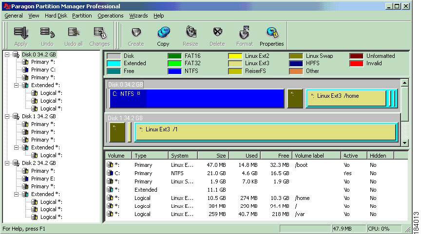
Figure 2-4 Partitioning Software
Step 25 Verify that the C: drive is the same size as or smaller than the LU. Figure 2-5 shows that Disk 0 on the C: drive is the same size as Disk 2 on the LU.
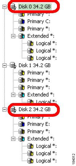
Figure 2-5 C: Drive (Disk 0) and LU (Disk 2) Sizes
Step 26 Right-click the local disk (Disk 0) and select Copy hard disk... from the right-click menu. The Copy Hdd 0 to window opens. (See Figure 2-6.)
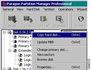
Figure 2-6 Copy the Hard Disk
Step 27 Select your LU (Disk 2) from the Destination disk pulldown menu, and then click OK. (See Figure 2-7.)
Figure 2-7 Select the Logical Unit from the Destination Disk
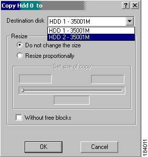
Step 28 Reboot your server. Paragon software copies the local disk to the LU.
Step 29 Power down the server.
Step 30 Remove the local drive from the host.
Step 31 Change the boot order when you boot the host to make the SRP disk the first disk in the boot order. (For more information about changing the boot order, refer to your hardware documentation.)
Step 32 Boot the server. The server boots from the SRP disk. The SRP disk becomes Drive C.