-
null
- Managing Your Rules Tables
- Using Rules Tables
- Adding and Removing Rules
- Editing Rules
- Finding and Replacing Items in Rules Tables
- Moving Rules and the Importance of Rule Order
- Enabling and Disabling Rules
- Using Sections to Organize Rules Tables
- Combining Rules
- Generating Policy Query Reports
- Optimizing Network Object Groups When Deploying Firewall Rules
- Expanding Object Groups During Discovery
- Working with Access Rules
- Understanding Access Rules
- Understanding Device Specific Access Rule Behavior
- Understanding Access Rule Address Requirements and How Rules Are Deployed
- Configuring Access Rules
- Configuring Expiration Dates for Access Rules
- Configuring Settings for Access Control
- Generating Analysis Reports
- Generating Hit Count Reports
- Importing Rules
- Optimizing Access Rules Automatically During Deployment
- Working with Inspection Rules
- Working with AAA Rules
Managing Firewall Services
Firewall Services manages firewall-related policies in Security Manager that apply to the Adaptive Security Appliance (ASA), PIX Firewall (PIX), Catalyst Firewall Services Module (FWSM), and security routers running Cisco IOS that include the Aggregation Services Router (ASR) and Integrated Services Router (ISR).
Each firewall policy comprises a collection of rules. The rules are loaded into rules tables incrementally, allowing you to scroll and view a partial rule set before the entire rule set is in memory. After rules are loaded the first time, they are retained in cache memory, so subsequent viewing of the rules tables is instantaneous. Cache memory is automatically cleared after an activity is approved or discarded, if a device is rediscovered, or when a policy is copied from another device. While rules are being loaded into tables, the action buttons on the page are grayed out until loading is complete; however, you can still make changes to the rules in the table during this process.
You can define firewall policies from "Device view," which enables you to configure local service policies on individual firewall devices and security appliances. You can then share these local policies with other devices. You can also define firewall policies from "Policy view," which enables you to define a general policy to assign to a set of devices or all devices. Policy view enables you to manage shared policies at the system level. For more information, see Chapter 6, "Managing Policies".
Firewall Services provides a uniform design for displaying firewall policy information for all supported platforms. This design is represented in the form of rules tables that are shown in the main work area. The options listed in the Firewall selector are based on the type of device for which rules are being created.
Security Manager manages the following types of policies under Firewall Services:
•![]() Firewall rules—Permit or deny a packet based on source address, destination address, source interface, and service. For more information, see Understanding Access Rules.
Firewall rules—Permit or deny a packet based on source address, destination address, source interface, and service. For more information, see Understanding Access Rules.
•![]() Inspection rules—Based on Context-Based Access Control (CBAC) to intelligently filter TCP and UDP packets based on application-layer protocol session information. Inspection rules apply to routers running IOS, PIX, ASA, and FWSM. For more information, see Understanding Inspection Rules.
Inspection rules—Based on Context-Based Access Control (CBAC) to intelligently filter TCP and UDP packets based on application-layer protocol session information. Inspection rules apply to routers running IOS, PIX, ASA, and FWSM. For more information, see Understanding Inspection Rules.
•![]() AAA rules—Control authentication, authorization, or accounting for traffic. For more information, see "Working with AAA Rules".
AAA rules—Control authentication, authorization, or accounting for traffic. For more information, see "Working with AAA Rules".
•![]() Web filter rules—Specify filter URLs using a filtering server such as Websense. For more information, see Understanding Web Filter Rules.
Web filter rules—Specify filter URLs using a filtering server such as Websense. For more information, see Understanding Web Filter Rules.
•![]() Transparent rules—EtherType rules used to configure non-IP related traffic policies through the firewall appliance when operating in transparent mode. In transparent mode, you can apply extended and EtherType access rules to an interface. For more information, see Working with Transparent Firewall Rules.
Transparent rules—EtherType rules used to configure non-IP related traffic policies through the firewall appliance when operating in transparent mode. In transparent mode, you can apply extended and EtherType access rules to an interface. For more information, see Working with Transparent Firewall Rules.
•![]() Zone-based firewall rules—Adaptation from the older interface-based inspection to a more flexible, more easily understood zone-based model. The concept of configuring features on interfaces has been broadened to allow firewall policy specification on a group of interfaces, which is referred to as a zone. For more information, see Understanding the Zone-based Firewall Rules.
Zone-based firewall rules—Adaptation from the older interface-based inspection to a more flexible, more easily understood zone-based model. The concept of configuring features on interfaces has been broadened to allow firewall policy specification on a group of interfaces, which is referred to as a zone. For more information, see Understanding the Zone-based Firewall Rules.
In addition to understanding the types of firewall policies that Security Manager supports, you need to understand the concept of policy inheritance. Inheritance refers to the capability of Security Manager to enforce hierarchical lists of first-match, rule-based policies such as access rules. Within the hierarchy, policies at a lower level in the hierarchy (called child policies) extend or override the properties of the policies that are directly above them in the hierarchy (called parent policies). Firewall policies can be inherited by a parent policy.
The ACEs from the mandatory rules are ordered from the highest group down to the device. Mandatory rules cannot be overridden. The ACEs from the Default rules are ordered in the opposite direction and can be overridden. For more information, see the following:
•![]() Understanding Rule Inheritance, page 6-4
Understanding Rule Inheritance, page 6-4
•![]() Working with Shared Policies in Device View, page 6-25.
Working with Shared Policies in Device View, page 6-25.
To better understand the difference between policy inheritance and policy assignment, see Inheritance vs. Assignment, page 6-6.
This chapter contains the following topics:
•![]() Working with Inspection Rules
Working with Inspection Rules
•![]() Working with Botnet Traffic Filter Rules
Working with Botnet Traffic Filter Rules
•![]() Working with Web Filter Rules
Working with Web Filter Rules
•![]() Working with Transparent Firewall Rules
Working with Transparent Firewall Rules
•![]() Working with Zone-based Firewall Rules
Working with Zone-based Firewall Rules
Managing Your Rules Tables
The following sections explain some of the basics of using rules tables, which appear in many of the firewall rules policies:
•![]() Finding and Replacing Items in Rules Tables
Finding and Replacing Items in Rules Tables
•![]() Moving Rules and the Importance of Rule Order
Moving Rules and the Importance of Rule Order
•![]() Using Sections to Organize Rules Tables
Using Sections to Organize Rules Tables
•![]() Generating Policy Query Reports
Generating Policy Query Reports
•![]() Optimizing Network Object Groups When Deploying Firewall Rules
Optimizing Network Object Groups When Deploying Firewall Rules
•![]() Expanding Object Groups During Discovery
Expanding Object Groups During Discovery
Using Rules Tables
Rules tables in Security Manager display sets of rules (for example, access rules) that make up a policy. These types of tables are used in only a select group of policies, but many of the firewall services rules policies use them. Rules tables are used when the order of the rules within the policy matter.
Figure 11-1 details the features in rules tables.
Figure 11-1 Rules Table Example
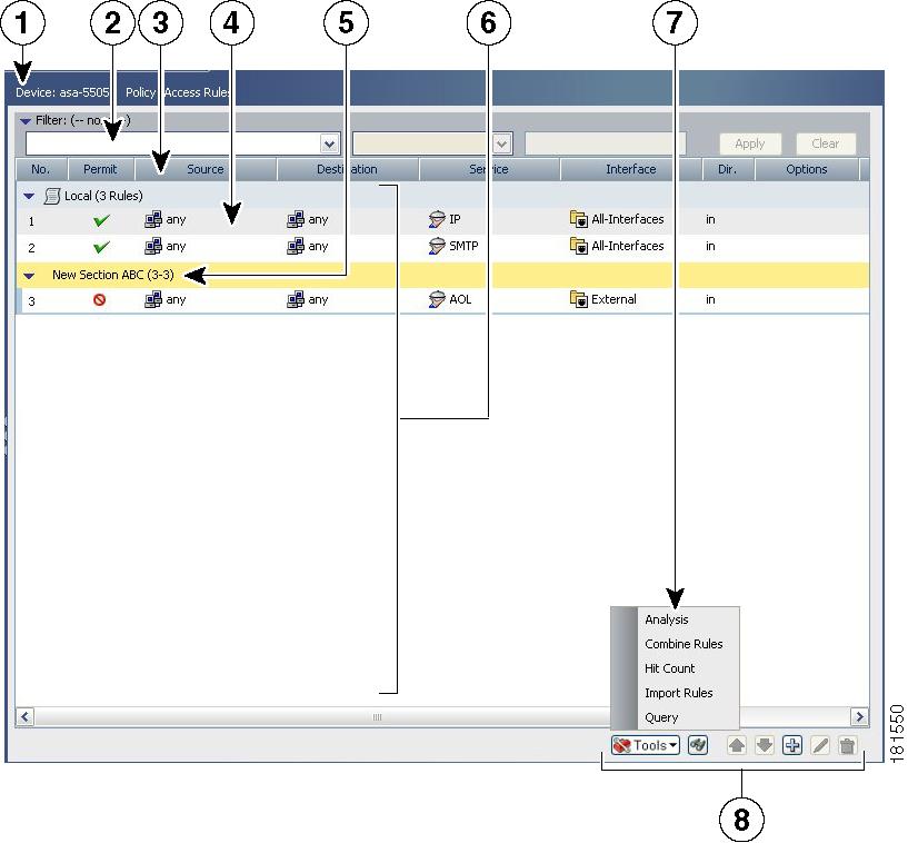
1 |
Device and Policy Identification Banner |
2 |
Table filter |
|---|---|---|---|
3 |
Table column headings |
4 |
Rules |
5 |
User-defined sections |
6 |
Rules listed in the work area |
7 |
Tools menu |
8 |
Table buttons |
Following is a more detailed descriptions of the rules table features:
•![]() Device and policy identification banner—The banner provides information about policy sharing and inheritance and includes the ability to perform some actions. For detailed information, see Using the Policy Banner, page 6-25.
Device and policy identification banner—The banner provides information about policy sharing and inheritance and includes the ability to perform some actions. For detailed information, see Using the Policy Banner, page 6-25.
•![]() Table filter—You can filter the rules displayed to help you find rules in a large table. For more information, see Filtering Tables, page 2-16.
Table filter—You can filter the rules displayed to help you find rules in a large table. For more information, see Filtering Tables, page 2-16.
•![]() Table column headings—You can sort by column and move, show, and hide columns. For more information, see Table Columns and Column Heading Features, page 2-18.
Table column headings—You can sort by column and move, show, and hide columns. For more information, see Table Columns and Column Heading Features, page 2-18.
•![]() Rules—The body of the table shows the rules that are included in the policy.
Rules—The body of the table shows the rules that are included in the policy.
•![]() User-defined sections—You can group rules into sections for your convenience. For more information, see Using Sections to Organize Rules Tables.
User-defined sections—You can group rules into sections for your convenience. For more information, see Using Sections to Organize Rules Tables.
•![]() Tools menu—Most rules table includes a Tools button that includes a list of additional tools you can use when working with the policy.
Tools menu—Most rules table includes a Tools button that includes a list of additional tools you can use when working with the policy.
•![]() Table buttons—Use the buttons below the table to do the following:
Table buttons—Use the buttons below the table to do the following:
–![]() Find and replace items within rules (button with the binoculars icon)—For more information, see Finding and Replacing Items in Rules Tables.
Find and replace items within rules (button with the binoculars icon)—For more information, see Finding and Replacing Items in Rules Tables.
–![]() Move and rearrange rules (up and down arrows)—For more information, see Moving Rules and the Importance of Rule Order.
Move and rearrange rules (up and down arrows)—For more information, see Moving Rules and the Importance of Rule Order.
–![]() Add rules to the table (+ icon)—For more information, see Adding and Removing Rules.
Add rules to the table (+ icon)—For more information, see Adding and Removing Rules.
–![]() Edit the selected rule (pencil icon)—For more information, see Editing Rules.
Edit the selected rule (pencil icon)—For more information, see Editing Rules.
–![]() Delete the selected rule (trash can icon)—For more information, see Adding and Removing Rules.
Delete the selected rule (trash can icon)—For more information, see Adding and Removing Rules.
Adding and Removing Rules
When you work with policies that use rules tables, like many of the firewall rules policies, you can add rules to the policy using several methods:
•![]() Add Row button (+ icon)—Clicking the Add Row button beneath the table is the standard method to add a new rule. Clicking this button opens the dialog box for adding rules that is specific to that type of policy. If you select a row or section heading, the new rule is added after the selected row. Otherwise, it is added at the end of the appropriate scope (typically, the local scope).
Add Row button (+ icon)—Clicking the Add Row button beneath the table is the standard method to add a new rule. Clicking this button opens the dialog box for adding rules that is specific to that type of policy. If you select a row or section heading, the new rule is added after the selected row. Otherwise, it is added at the end of the appropriate scope (typically, the local scope).
•![]() Right-click a row and select Add Row—This is equivalent to selecting a row and clicking the Add Row button.
Right-click a row and select Add Row—This is equivalent to selecting a row and clicking the Add Row button.
•![]() Copy and paste—If you want to create a new rule that is similar to an existing rule, you can select the rule, right-click and select Copy, then select the row after which you want to place the rule, right-click and select Paste. This creates a duplicate rule, which you can select and edit (see Editing Rules).
Copy and paste—If you want to create a new rule that is similar to an existing rule, you can select the rule, right-click and select Copy, then select the row after which you want to place the rule, right-click and select Paste. This creates a duplicate rule, which you can select and edit (see Editing Rules).
•![]() Cut and paste—Cut and paste is similar to copy and paste, except you are deleting the existing rule when you select the Cut command. Instead of cut and paste, consider moving the rule (see Moving Rules and the Importance of Rule Order).
Cut and paste—Cut and paste is similar to copy and paste, except you are deleting the existing rule when you select the Cut command. Instead of cut and paste, consider moving the rule (see Moving Rules and the Importance of Rule Order).
When you no longer need a rule, you can remove it by selecting the rule and clicking the Delete Row button (trash can icon).

Tip ![]() Rather than deleting a rule, consider first disabling the rule. By disabling a rule, you remove it from the device (when you redeploy the configuration) without removing it from Security Manager. Then, if you discover that you really needed that rule after all, you can simply enable it and redeploy the configuration. If you delete the rule, you would have to recreate it (there is no undo function). Thus, you might want to develop a policy of deleting rules only after they have been disabled for a certain amount of time. For more information, see Enabling and Disabling Rules.
Rather than deleting a rule, consider first disabling the rule. By disabling a rule, you remove it from the device (when you redeploy the configuration) without removing it from Security Manager. Then, if you discover that you really needed that rule after all, you can simply enable it and redeploy the configuration. If you delete the rule, you would have to recreate it (there is no undo function). Thus, you might want to develop a policy of deleting rules only after they have been disabled for a certain amount of time. For more information, see Enabling and Disabling Rules.
Related Topics
•![]() Moving Rules and the Importance of Rule Order
Moving Rules and the Importance of Rule Order
•![]() Using Sections to Organize Rules Tables
Using Sections to Organize Rules Tables
Editing Rules
To edit an existing rule in any of the rules policies that use rules tables, select the rule and click the Edit Row button, or right-click and select Edit Row. This allows you to edit all aspects of the selected rule.
Tip ![]() You cannot edit any aspect of an inherited rule from a local device rule policy. Edit inherited rules in Policy view.
You cannot edit any aspect of an inherited rule from a local device rule policy. Edit inherited rules in Policy view.
For most rule tables, you can also edit specific attributes, or table cells, instead of editing the entire rule, using commands in the right-click menu. You cannot do cell-level editing for web filter rules on IOS devices, or for Botnet rules.
The ability to edit a cell is limited by whether it makes sense to edit the content. For example, Inspection Rules have many limitations based on how the rule is configured:
•![]() If you selected to apply the rule to All Interfaces, you cannot edit source or destination addresses, the interface, or the direction of the rule.
If you selected to apply the rule to All Interfaces, you cannot edit source or destination addresses, the interface, or the direction of the rule.
•![]() If you selected Default Inspection Traffic for the traffic match criteria (without selecting the option to limit inspection between source and destination), or Custom Destination Ports, you cannot edit source or destination addresses.
If you selected Default Inspection Traffic for the traffic match criteria (without selecting the option to limit inspection between source and destination), or Custom Destination Ports, you cannot edit source or destination addresses.
•![]() If you selected Destination Address and Port (IOS), you cannot edit source addresses.
If you selected Destination Address and Port (IOS), you cannot edit source addresses.
The following cell-level commands are available:
•![]() Add <Attribute Type>—When you select multiple rows and right-click a Source, Destination, Services, or Interface cell, you can select the Add command to append entries to the data currently in the selected cells. The Add command's full name includes the name of the attribute, for example, Add Source.
Add <Attribute Type>—When you select multiple rows and right-click a Source, Destination, Services, or Interface cell, you can select the Add command to append entries to the data currently in the selected cells. The Add command's full name includes the name of the attribute, for example, Add Source.
•![]() Edit <Attribute Type>—Most attributes allow you to edit the content. Editing replaces the content of the cell. You can edit a single cell, or select multiple rows and edit the contents of the same type of cell in all rows at once. The Edit command's full name includes the name of the attribute, for example, Edit Interfaces.
Edit <Attribute Type>—Most attributes allow you to edit the content. Editing replaces the content of the cell. You can edit a single cell, or select multiple rows and edit the contents of the same type of cell in all rows at once. The Edit command's full name includes the name of the attribute, for example, Edit Interfaces.
•![]() Edit <Entry>—In some cases, when you edit Source, Destination, Services, or Interfaces, you can select an entry in the cell and edit just that entry. For example, if the Sources cell contains three network/host objects and an IP address, you can select any of them and edit the entry. The edit command includes the name of the entry, for example, Edit HostObject.
Edit <Entry>—In some cases, when you edit Source, Destination, Services, or Interfaces, you can select an entry in the cell and edit just that entry. For example, if the Sources cell contains three network/host objects and an IP address, you can select any of them and edit the entry. The edit command includes the name of the entry, for example, Edit HostObject.
•![]() Remove <Entry>—In some cases, when you edit Source, Destination, Services, or Interfaces, you can select an entry in the cell and remove the entry. You cannot remove the last entry in the cell, because the rule would become invalid. The remove command includes the name of the entry, for example, Remove IP.
Remove <Entry>—In some cases, when you edit Source, Destination, Services, or Interfaces, you can select an entry in the cell and remove the entry. You cannot remove the last entry in the cell, because the rule would become invalid. The remove command includes the name of the entry, for example, Remove IP.
•![]() Create <Object Type> Object from Cell Contents—In the Sources, Destinations, and Services cells, you can select the Create command to create a policy object of the appropriate type. You can also select an entry in the cell and create a policy object from just the selected item. The create command includes the policy object type you can create, and the name of the item that is the source for the object, either cell contents for everything in the cell, or the name of an entry if you selected one.
Create <Object Type> Object from Cell Contents—In the Sources, Destinations, and Services cells, you can select the Create command to create a policy object of the appropriate type. You can also select an entry in the cell and create a policy object from just the selected item. The create command includes the policy object type you can create, and the name of the item that is the source for the object, either cell contents for everything in the cell, or the name of an entry if you selected one.
•![]() Show <Attribute Type> Contents; Show <Entry> Contents—The show commands let you view the actual data defined in the cell. The results depend on the view you are in:
Show <Attribute Type> Contents; Show <Entry> Contents—The show commands let you view the actual data defined in the cell. The results depend on the view you are in:
–![]() Device View, Map View, or Import Rules—You are shown the actual IP addresses, services, or interfaces to which the rule will apply for the specific device. For example, if the rule uses network/host objects, you will see the specific IP addresses defined by the objects. If the rule uses interface objects, you will see the specific interfaces defined on the device that the object identifies, if any.
Device View, Map View, or Import Rules—You are shown the actual IP addresses, services, or interfaces to which the rule will apply for the specific device. For example, if the rule uses network/host objects, you will see the specific IP addresses defined by the objects. If the rule uses interface objects, you will see the specific interfaces defined on the device that the object identifies, if any.
The IP addresses for network/host objects are sorted in ascending order on the IP address, and then descending order on the subnet mask.
Service objects are sorted on protocol, source port, and destination port.
Interface objects are listed in alphabetical order. If the interface is selected because it matches a pattern in an interface object, the pattern is listed first, and the matching interface is shown in parentheses. For example, "* (Ethernet1)" indicates that the Ethernet1 interface on the device is selected because it matches the * pattern (which matches all interfaces).
•![]() Policy View—You are shown the patterns defined in the policy objects and entries defined for the policy. Entries are sorted alphabetically, with numbers and special characters coming first.
Policy View—You are shown the patterns defined in the policy objects and entries defined for the policy. Entries are sorted alphabetically, with numbers and special characters coming first.
Related Topics
•![]() Moving Rules and the Importance of Rule Order
Moving Rules and the Importance of Rule Order
•![]() Using Sections to Organize Rules Tables
Using Sections to Organize Rules Tables
Finding and Replacing Items in Rules Tables
In policies that use rules tables, you can search for items in some cells and selectively replace them. The cells you can search depend on the policy. You can use wildcard characters to find items based on pattern matching, for example, so that you can replace several related networks with a new network/host policy object defined for them.
To use find and replace, click the Find and Replace (binoculars icon) button at the bottom of any policy that uses rules tables to open the Find and Replace Dialog Box, page I-91. In the Firewall folder, this includes AAA rules, access rules, inspection rules, zone based firewall rules, and web filter rules (for ASA/PIX/FWSM devices only). For ASA/PIX/FWSM devices, it also includes the NAT translation rules policy (but not for every combination of context and operational mode) and the IOS, QoS, and connection rules platform service policy.
When searching for items, you select the type of item, the columns you want to search, and enter the string that you want to find and optionally, the string you want to use to replace it. You can find and replace the following types of items:
•![]() Network—A network/host object name or the IP address of a host or network.
Network—A network/host object name or the IP address of a host or network.
•![]() Service—A service object name or protocol and port, for example TCP/80. The search is syntactic, not semantic, that is, if you are searching for TCP/80 and a rule uses HTTP, the search results will not find it.
Service—A service object name or protocol and port, for example TCP/80. The search is syntactic, not semantic, that is, if you are searching for TCP/80 and a rule uses HTTP, the search results will not find it.
•![]() Interface Role—An interface name or interface role object name.
Interface Role—An interface name or interface role object name.
•![]() Text—A text string in a Description field.
Text—A text string in a Description field.
The following are some examples of what you might do with find and replace:
•![]() If you create a new network/host object named network10.100 for all networks in the 10.100.0.0/16 range, you can search and replace all subordinate network specifications. For example, you can search for ^10.100* to find all addresses like 10.100.10.0/24. Select the Find Whole Words Only and Allow Wildcard options, and enter network10.100 as the replacement string. Because you selected Find Whole Words Only, the string that is replaced is the entire 10.100.10.0/24 string, not just the 10.100 portion.
If you create a new network/host object named network10.100 for all networks in the 10.100.0.0/16 range, you can search and replace all subordinate network specifications. For example, you can search for ^10.100* to find all addresses like 10.100.10.0/24. Select the Find Whole Words Only and Allow Wildcard options, and enter network10.100 as the replacement string. Because you selected Find Whole Words Only, the string that is replaced is the entire 10.100.10.0/24 string, not just the 10.100 portion.
•![]() If you want to find all rules that use IP addresses (instead of network/host objects), you can search for *.*.*.* to find all host or network IP addresses. You can then selectively edit the cell while the Find and Replace dialog box is open.
If you want to find all rules that use IP addresses (instead of network/host objects), you can search for *.*.*.* to find all host or network IP addresses. You can then selectively edit the cell while the Find and Replace dialog box is open.
•![]() If you want to replace all interface role objects that include "side" in the name (such as inside and outside) with the interface role object named External, search for *side with the Find Whole Words Only and Allow Wildcard options selected, and enter External in the Replace field.
If you want to replace all interface role objects that include "side" in the name (such as inside and outside) with the interface role object named External, search for *side with the Find Whole Words Only and Allow Wildcard options selected, and enter External in the Replace field.
Related Topics
Moving Rules and the Importance of Rule Order
Rules policies that use rules tables are ordered lists. That is, the top to bottom order of the rules matters and has an effect on the policy.
When the device analyzes a packet against a rules policy, the device searches the rules in order from top to bottom. The first rule that matches the packet is the rule that is applied to the packet, and all subsequent rules are ignored. Thus, if you place a general rule pertaining to IP traffic before a more specific rule pertaining to HTML traffic for a given source or destination, the more specific rule might never be applied.
For access control rules, you can use the rules analysis tool to help identify when rule order will prevent a rule from ever being applied to traffic (for more information, see Generating Analysis Reports). For other rules policies, carefully inspect the table to spot problems with rule order.
When you find that you need to rearrange the order of a rule, select the rule that needs to be moved and click the Up Row (up arrow) or Down Row (down arrow) buttons as appropriate. If these buttons do not appear beneath the rules table, rule order does not matter and you cannot rearrange them.
If you use sections to organize your rules, you can move rules only within the section. When you move rules that are outside the sections, you can move them above or below the section. For more information about working with sections, see Using Sections to Organize Rules Tables.
Related Topics
•![]() Using Sections to Organize Rules Tables
Using Sections to Organize Rules Tables
Enabling and Disabling Rules
You can enable and disable individual rules in a policy that uses rules tables, such as most firewall services rules policies. Your change takes effect when you redeploy the configuration to the device.
If a rule is disabled, it appears in the table overlain with hash marks. Disabled rules are downloaded to a device as disabled only if the device supports that option (for example, for ASA/PIX 7.0+ devices). Otherwise, they are kept in the rules policy in Security Manager as a convenience so that you can easily enable needed rules without recreating them. Thus, it is often wise to disable a rule that you believe you no longer need instead of immediately deleting it.
To change whether a rule is enabled or disabled, select the rule, right-click and select Enable or Disable, as appropriate.
Related Topics
•![]() Moving Rules and the Importance of Rule Order
Moving Rules and the Importance of Rule Order
•![]() Using Sections to Organize Rules Tables
Using Sections to Organize Rules Tables
Using Sections to Organize Rules Tables
You can organize policies that use rules tables into sections. There are two types of sections:
•![]() Scopes, which define inheritance relationships between a policy and an inherited policy. These sections are automatically created when you inherit policies. For more information, see Understanding Rule Inheritance, page 6-4.
Scopes, which define inheritance relationships between a policy and an inherited policy. These sections are automatically created when you inherit policies. For more information, see Understanding Rule Inheritance, page 6-4.
•![]() User-defined sections, which are convenient groupings that help you organize rules so that you can evaluate and edit the policy more easily. These types of sections are most useful for policies that contain a large number of rules.
User-defined sections, which are convenient groupings that help you organize rules so that you can evaluate and edit the policy more easily. These types of sections are most useful for policies that contain a large number of rules.
All rules within a section must be sequential; you cannot group rules randomly. If you want to identify non-contiguous rules as being related, you can assign the same category to the rules.
User-defined sections are set off visually from the other rules in the table by a color border and a section heading. The heading contains, left to right, an open/close arrow for showing or hiding the contents of a section, a band of color identifying the category you assigned the section (if any), the section name, the first and last rule number contained in the section (for example, 4-8), and the description, if any, you gave the section.
Whether you create user-defined sections is completely up to you. If you decide creating these types of sections is worthwhile, the following information explains how to create and use them:
•![]() To create a new section, right-click a row that you want to place the section and select Include in New Section. (You can also use Shift+click to select a block of rules.) You are prompted for a name, description, and category for the section (the name is the only required element).
To create a new section, right-click a row that you want to place the section and select Include in New Section. (You can also use Shift+click to select a block of rules.) You are prompted for a name, description, and category for the section (the name is the only required element).
•![]() To move existing rules into a section, select one or more contiguous rules, right-click and select Include in Section <name of section>. This command appears only if the selected rows are next to an existing section. If the rows you want to add to a section are not currently next to the section, you can do one of two things: move the rules until they are next to the section; cut the rules and paste them into the section.
To move existing rules into a section, select one or more contiguous rules, right-click and select Include in Section <name of section>. This command appears only if the selected rows are next to an existing section. If the rows you want to add to a section are not currently next to the section, you can do one of two things: move the rules until they are next to the section; cut the rules and paste them into the section.
•![]() You cannot move a section. Instead, you need to move the rules that are outside of the section around it. When you move a rule that is next to, but not within, a section, the rule jumps over the section.
You cannot move a section. Instead, you need to move the rules that are outside of the section around it. When you move a rule that is next to, but not within, a section, the rule jumps over the section.
•![]() You cannot move a rule outside of or through a section. A section defines the borders within which you can move rules. If you want to move rules out of a section and back into the Local scope section, select one or more contiguous rules, right-click and select Remove from Section <name of section>. The rules must be at the beginning or end of the section to use this command. If they are not, you can either move the rules until they are, or use cut and paste to move them out of the section.
You cannot move a rule outside of or through a section. A section defines the borders within which you can move rules. If you want to move rules out of a section and back into the Local scope section, select one or more contiguous rules, right-click and select Remove from Section <name of section>. The rules must be at the beginning or end of the section to use this command. If they are not, you can either move the rules until they are, or use cut and paste to move them out of the section.
•![]() To add a new rule to a section, select the rule after which you want to create the rule before clicking the Add Row button. To place it at the beginning of the section, select the section heading.
To add a new rule to a section, select the rule after which you want to create the rule before clicking the Add Row button. To place it at the beginning of the section, select the section heading.
If you want to create a rule after, but outside of, a section, you can either create it as the last rule in the section and then remove it from the section, or create it just above the section and click down arrow button.
•![]() You can change the name, description, or category of a section by right-clicking the section heading and selecting Edit Section.
You can change the name, description, or category of a section by right-clicking the section heading and selecting Edit Section.
•![]() When you delete a section, all rules contained in the section are retained and moved back into the Local scope section. No rules are deleted. To delete a section, right-click the section heading and select Delete Section.
When you delete a section, all rules contained in the section are retained and moved back into the Local scope section. No rules are deleted. To delete a section, right-click the section heading and select Delete Section.
•![]() If you use the Combine Rules tool, the resulting combined rules respect your sections. Rules that are in a section can be combined only with other rules in that section.
If you use the Combine Rules tool, the resulting combined rules respect your sections. Rules that are in a section can be combined only with other rules in that section.
Related Topics
•![]() Moving Rules and the Importance of Rule Order
Moving Rules and the Importance of Rule Order
Combining Rules
Access rules and AAA rules policies can grow over time to include a large number of rules. The size of these policies can make it difficult to manage them. To alleviate this problem, you can use the rule combiner tool to reduce the number of rules in a policy without changing how the policy handles traffic.
Tip ![]() Combining rules can dramatically compress the number of access rules required to implement a particular security policy. For example, a policy that required 3,300 access rules might only require 40 rules after hosts and services are efficiently grouped.
Combining rules can dramatically compress the number of access rules required to implement a particular security policy. For example, a policy that required 3,300 access rules might only require 40 rules after hosts and services are efficiently grouped.
You might have several rules that allow a specific range of services to various trusted hosts (as sources) to various public servers (as destinations). If you have 10 rules applying to this situation, it is possible that those 10 rules can be combined into a single rule. You could then create new policy objects for the collection of services (for example, AllowedServices), hosts (for example, TrustedHosts), and servers (for example, PublicServers). To create the new objects during rule combination, you can right-click the newly-combined cells and select Create Network (or Service) Object from Cell Contents.
For example, you might have two rules for interface FastEthernet0:
•![]() Permit TCP for source 10.100.10.1 to destination 10.100.12.1
Permit TCP for source 10.100.10.1 to destination 10.100.12.1
•![]() Permit TCP for source 10.100.10.1 to destination 10.100.13.1
Permit TCP for source 10.100.10.1 to destination 10.100.13.1
These can be combined into a single rule: permit TCP for source 10.100.10.1 to destination 10.100.12.1, 10.100.13.1.
Multidimensional sorting is used to combine rules. For example, for access rules:
1. ![]() Rules are sorted by their sources, so rules with the same source are placed together.
Rules are sorted by their sources, so rules with the same source are placed together.
2. ![]() Same-source rules are sorted by destination, so rules with the same source and destination are placed together.
Same-source rules are sorted by destination, so rules with the same source and destination are placed together.
3. ![]() Same-source and same-destination rules are combined into a single rule, and the services are concatenated.
Same-source and same-destination rules are combined into a single rule, and the services are concatenated.
4. ![]() Adjacent rules are checked to see if they have the same source and service. If so, they are combined into a single rule, and the destinations are concatenated.
Adjacent rules are checked to see if they have the same source and service. If so, they are combined into a single rule, and the destinations are concatenated.
5. ![]() Adjacent rules are checked to see if they have the same destination and service. If so, they are combined into a single rule, and the sources are concatenated.
Adjacent rules are checked to see if they have the same destination and service. If so, they are combined into a single rule, and the sources are concatenated.
Sorting is repeated based on destination and service in place of source.
Tip ![]() Rules from different sections are never combined. Any sections you create to organize rules limit the scope of the possible combinations.
Rules from different sections are never combined. Any sections you create to organize rules limit the scope of the possible combinations.
Related Topics
Step 1 ![]() Select the policy whose rules you want to combine from the Firewall folder. You can combine rules for the following types of policy:
Select the policy whose rules you want to combine from the Firewall folder. You can combine rules for the following types of policy:
•![]() AAA rules
AAA rules
•![]() Access rules
Access rules
Step 2 ![]() If you want the tool to limit possible combinations to a specific group of rules, select them. You can select rules using Shift+click and Ctrl+click, select all rules in a section by selecting the section heading, or all rules within a scope by selecting the scope heading (for example, Local). To not limit the tool, do not select anything in the table. Keep the following in mind:
If you want the tool to limit possible combinations to a specific group of rules, select them. You can select rules using Shift+click and Ctrl+click, select all rules in a section by selecting the section heading, or all rules within a scope by selecting the scope heading (for example, Local). To not limit the tool, do not select anything in the table. Keep the following in mind:
•![]() In Device view, you can save combinations only for local rules. The tool will allow you to run it on shared and inherited rules, but you cannot save the results. If you do not select any rules, the default is to consider all local scope rules.
In Device view, you can save combinations only for local rules. The tool will allow you to run it on shared and inherited rules, but you cannot save the results. If you do not select any rules, the default is to consider all local scope rules.
•![]() To combine rules in shared policies, you must run the tool in Policy view. If you do not select any rules, the default is to consider all mandatory rules.
To combine rules in shared policies, you must run the tool in Policy view. If you do not select any rules, the default is to consider all mandatory rules.
You are warned if you try to run the tool when you cannot save the results.
Step 3 ![]() Click the Tools button located below the table, then select Combine Rules to open the Combine Rules Selection Summary Dialog Box, page I-103.
Click the Tools button located below the table, then select Combine Rules to open the Combine Rules Selection Summary Dialog Box, page I-103.
Step 4 ![]() Select the columns you want the rule to consider combining. If you do not select certain columns, the combined rules must have the identical settings in those columns to be combined.
Select the columns you want the rule to consider combining. If you do not select certain columns, the combined rules must have the identical settings in those columns to be combined.
You can also elect to consider combining the rules you selected or all rules within the policy.
Tip ![]() If a column type is not listed, then combined rules must have the identical content in those cells except for the Description cell. Rules that have different content for the cells are not combined.
If a column type is not listed, then combined rules must have the identical content in those cells except for the Description cell. Rules that have different content for the cells are not combined.
Step 5 ![]() Click OK to generate the combination and display the results in the Rule Combiner Results Dialog Box, page I-104.
Click OK to generate the combination and display the results in the Rule Combiner Results Dialog Box, page I-104.
Analyze the results and evaluate whether you want to save the combinations. You must save all or none, you cannot pick and choose which combinations to save.
For more information on evaluating the results, see Understanding Rule Combiner Results.
Step 6 ![]() Click OK to replace the original rules in the rules tables with the combined rules.
Click OK to replace the original rules in the rules tables with the combined rules.
Understanding Rule Combiner Results
When you run the Combine Rules tool as described in Combining Rules, the results of the combination are displayed in the Rule Combiner Results Dialog Box, page I-104.
The dialog box shows the new rules in the upper table. Any new rules are indicated as modified or combined rules, and the changed cells are outlined in red (for an example, see Figure 11-2). When you select a new rule in the upper table, the lower table shows the old rules that were combined to create the new rule. In this example, the two old rules had the same destination, service, and interface, and the two distinct sources were concatenated to form the new rule.
The top of the report summarizes the results. In this example, 5700 rules were reduced to 96 rules.
You can refine some elements of the results in this window:
•![]() You can right-click on the Source, Destination, and Service cells with multiple elements and select Create Network (or Service) Object from Cell Contents to create a new policy object that contains the contents of the combined cell. The new object replaces the contents of the cell.
You can right-click on the Source, Destination, and Service cells with multiple elements and select Create Network (or Service) Object from Cell Contents to create a new policy object that contains the contents of the combined cell. The new object replaces the contents of the cell.
You can also automatically create network object groups in the deployed configuration to replace the comma-separated values in a rule table cell. The network objects are created during deployment, and they do not affect the content of your rules policy. To enable this option, select Tools > Security Manager Administration > Deployment to open the Deployment Page, page A-7 and select Create Object Groups for Multiple Sources, Destinations, or Services in a Rule. This option affects only ASA, PIX, and FWSM devices.
•![]() You can right-click on Description and select Edit Description to change the description. The descriptions of combined rules are a concatenation of the descriptions of the old rules separated by new lines.
You can right-click on Description and select Edit Description to change the description. The descriptions of combined rules are a concatenation of the descriptions of the old rules separated by new lines.
The combined results are not applied to the policy until you click OK. If you do not like the results of the combination, click Cancel and consider selecting smaller groups of rules to limit the scope of the Combine Rules tool.
Tip ![]() If you click OK but then decide you do not want to accept the changes, you have two options. First, make sure you do not click Save on the policy page, select a different policy, and click No when prompted to save your changes to the policy. If you already clicked Save, you can still back out the changes by discarding your activity or configuration session (for example, File > Discard in non-Workflow mode), but this also discards any other changes you have made to other policies. Once you submit your changes or your activity is approved, you cannot undo your changes.
If you click OK but then decide you do not want to accept the changes, you have two options. First, make sure you do not click Save on the policy page, select a different policy, and click No when prompted to save your changes to the policy. If you already clicked Save, you can still back out the changes by discarding your activity or configuration session (for example, File > Discard in non-Workflow mode), but this also discards any other changes you have made to other policies. Once you submit your changes or your activity is approved, you cannot undo your changes.
From this report, you can also click Detail Report to create a report in HTML of the results. For combined rules that have a lot of entries in cells, this report makes it easier to read the results. You can also print or save the report for later use.
Figure 11-2 Example of Rule Combiner Results
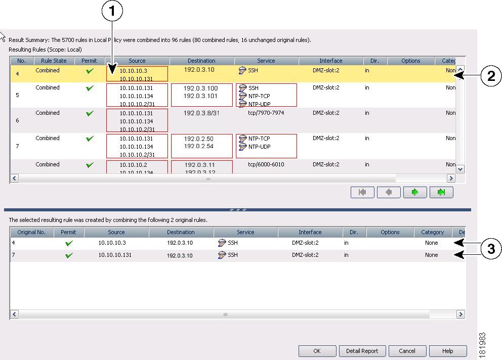
1 |
Combined cell |
2 |
Newly combined rule |
3 |
Original rules |
Related Topics
Generating Policy Query Reports
For most of the firewall rules policies, you can generate policy query reports that can help you evaluate your rules. With policy query reports, you can determine what rules already exist for a particular source, destination, interface, service, or zone before creating new rules to apply to those items.
To a limited degree, you can also determine if there are some blocking rules that prevent a rule from being used, or redundant rules that you can delete. If you are evaluating access rules, however, it is better to use the more powerful rule analysis tool to determine these problems.
When you create a policy query, you describe the traffic that interests you, much the same way you describe traffic when creating a rule. Creating a query is essentially the same as creating a rule, but you might want to describe the rule more broadly to capture a wider set of traffic so you can see a set of related rules rather than a single rule or a limited number of rules. The query you create depends on the information you are trying to discover.
The possible extent of a query depends on the view you are in:
•![]() Device or Map view—The query is limited to the selected device. However, you can query across all supported rule types. This allows you to compare different types of rules that apply to the same traffic.
Device or Map view—The query is limited to the selected device. However, you can query across all supported rule types. This allows you to compare different types of rules that apply to the same traffic.
•![]() Policy view—The query is limited to the selected policy. You see only rules that are defined in that policy, and you cannot query other types of policies. If you want to query a shared policy while examining other policies, select a device that is assigned to the shared policy, and query the policy from the device in Device view.
Policy view—The query is limited to the selected policy. You see only rules that are defined in that policy, and you cannot query other types of policies. If you want to query a shared policy while examining other policies, select a device that is assigned to the shared policy, and query the policy from the device in Device view.
Related Topics
•![]() Inspection Rules Page, page I-16
Inspection Rules Page, page I-16
•![]() Web Filter Rules Page (PIX/ASA), page I-45
Web Filter Rules Page (PIX/ASA), page I-45
•![]() Zone-based Firewall Rules Page, page I-54
Zone-based Firewall Rules Page, page I-54
Step 1 ![]() Select the policy that you want to query from the Firewall folder. You can query any of the following types of policy:
Select the policy that you want to query from the Firewall folder. You can query any of the following types of policy:
•![]() AAA Rules
AAA Rules
•![]() Access Rules
Access Rules
•![]() Inspection Rules
Inspection Rules
•![]() Web Filter Rules (PIX/ASA/FWSM)
Web Filter Rules (PIX/ASA/FWSM)
•![]() Zone Based Rules
Zone Based Rules
Step 2 ![]() Click the Tools button located below the table, then select Query to open the Querying Device or Policy Dialog Box, page I-97.
Click the Tools button located below the table, then select Query to open the Querying Device or Policy Dialog Box, page I-97.
Step 3 ![]() Enter the parameters that define the rules you want to query. When setting up your query, you must select at least one rule type; enabled, disabled or both; permitted, denied, or both; and mandatory, default, or both. For detailed information about the query parameters, see Querying Device or Policy Dialog Box, page I-97.
Enter the parameters that define the rules you want to query. When setting up your query, you must select at least one rule type; enabled, disabled or both; permitted, denied, or both; and mandatory, default, or both. For detailed information about the query parameters, see Querying Device or Policy Dialog Box, page I-97.
In Policy view, you cannot change the type of rule you are querying. In Device view, you can query any combination of rule types.
Step 4 ![]() Click OK to view the rules that match the criteria in the Policy Query Results Dialog Box, page I-99.
Click OK to view the rules that match the criteria in the Policy Query Results Dialog Box, page I-99.
For an example of a policy query report, see Understanding Policy Query Results.
Understanding Policy Query Results
Figure 11-3 shows an example of a policy query report on access rules. The criteria does not limit source, destination, service, and interface parameters, but limits the query to enabled rules. Both shared and local rules are included.
Figure 11-3 Policy Query Results
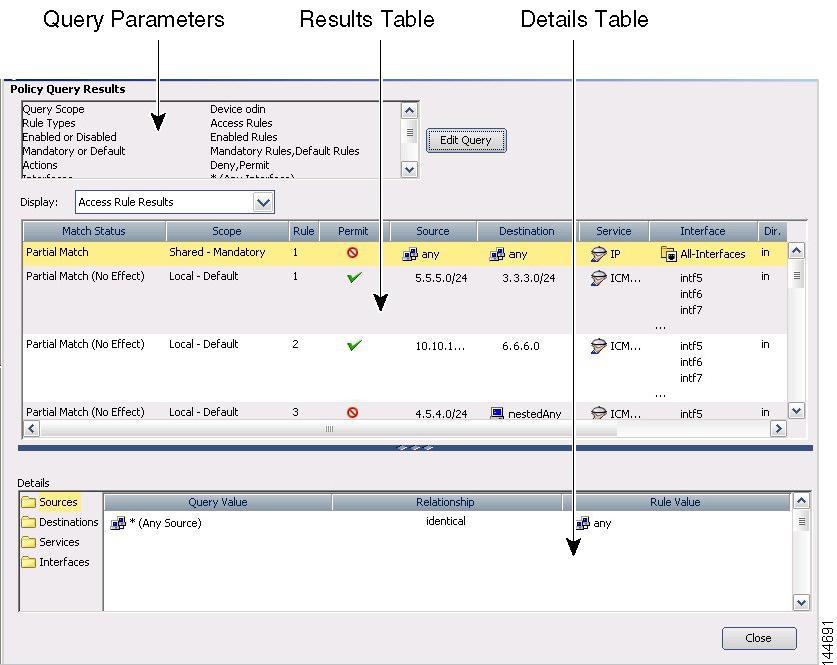
To read the report, consider the following report sections:
•![]() Query Parameters—The top portion of the report specifies the parameters you entered for the query. If you want to change them, click Edit Query to open the Querying Device or Policy Dialog Box, page I-97, where you can make your changes and regenerate the report.
Query Parameters—The top portion of the report specifies the parameters you entered for the query. If you want to change them, click Edit Query to open the Querying Device or Policy Dialog Box, page I-97, where you can make your changes and regenerate the report.
•![]() Results Table—This table lists all rules that match your query. If you queried more than one type of rule, select the rule type you want to examine in the Display field. The columns in the table are the same as those for that type of rule, except for the following:
Results Table—This table lists all rules that match your query. If you queried more than one type of rule, select the rule type you want to examine in the Display field. The columns in the table are the same as those for that type of rule, except for the following:
–![]() Match Status—Indicates how the rule matches your query:
Match Status—Indicates how the rule matches your query:
–![]() Complete Match—The rule matches all query parameters.
Complete Match—The rule matches all query parameters.
–![]() Partial Match—All of the search criteria overlap or are a superset of the matched rule.
Partial Match—All of the search criteria overlap or are a superset of the matched rule.
For example, if you have a rule defined with a source address of 10.100.20.0/24, a destination address of 10.200.100.0/24 and a service of IP, and your query is to search for a source of 10.100.20.0/24, the match status is shown as a partial match because the query results represent only a portion of the rule's definition.
–![]() No Effect—Rules are blocked by other matching rules, or a conflict exists that has no effect.
No Effect—Rules are blocked by other matching rules, or a conflict exists that has no effect.
For example, you might have two matching rules, A and B. If rule A's source address, destination address, and services are equivalent to, or contain, those of rule B, rule B is blocked by rule A. Thus, rule B will have no effect on traffic.
In another example, you might have a global mandatory rule that permits a service, but a rule at the device (local) level denies the service. Because rules are recognized on a first-match basis, after discovering a match at the mandatory global scope, no other rules are checked. The local rule has no effect; the service is permitted, not denied. You should edit your policies to ensure you get the desired results.
–![]() Scope—Identifies whether a rule is shared or local, mandatory or default.
Scope—Identifies whether a rule is shared or local, mandatory or default.
•![]() Details Table—The details table shows the detailed query match information for the rule selected in the results table. The folders on the left represent the attributes for which you can see detailed information. Select a folder to view the details.
Details Table—The details table shows the detailed query match information for the rule selected in the results table. The folders on the left represent the attributes for which you can see detailed information. Select a folder to view the details.
The details show the query value, which is the parameter you defined, and the item in the rule that matches the parameter. The matching relationship is one of the following:
–![]() Identical—The parameter is identical to the value in the rule. In Figure 11-3, the source folder is selected, and the result shows that the rule value, any, is an identical match to the query parameter *, which is equivalent to any source address.
Identical—The parameter is identical to the value in the rule. In Figure 11-3, the source folder is selected, and the result shows that the rule value, any, is an identical match to the query parameter *, which is equivalent to any source address.
–![]() Contains—The parameter is a superset that contains the value in the rule. For example, the query parameter might have been a network/host object, and the rule used an IP address that was part of the object definition.
Contains—The parameter is a superset that contains the value in the rule. For example, the query parameter might have been a network/host object, and the rule used an IP address that was part of the object definition.
–![]() Is contained by—The parameter is a subset nested within the value of the rule.
Is contained by—The parameter is a subset nested within the value of the rule.
–![]() Overlaps—The query parameter shows results that overlap between more than one policy object used in the rule. For example, the service query parameter was tcp/70-90 and the results show a service defined as tcp/80-100.
Overlaps—The query parameter shows results that overlap between more than one policy object used in the rule. For example, the service query parameter was tcp/70-90 and the results show a service defined as tcp/80-100.
Related Topics
•![]() Generating Policy Query Reports
Generating Policy Query Reports
•![]() Querying Device or Policy Dialog Box, page I-97
Querying Device or Policy Dialog Box, page I-97
•![]() Inspection Rules Page, page I-16
Inspection Rules Page, page I-16
•![]() Web Filter Rules Page (PIX/ASA), page I-45
Web Filter Rules Page (PIX/ASA), page I-45
•![]() Zone-based Firewall Rules Page, page I-54
Zone-based Firewall Rules Page, page I-54
Optimizing Network Object Groups When Deploying Firewall Rules
When you deploy firewall rules policies to an ASA, PIX, or FWSM device, you can configure Security Manager to evaluate and optimize the network/host policy objects that you use in the rules when it creates the associated network object groups on the device. Optimization merges adjacent networks and removes redundant network entries. This reduces the runtime access list data structures and the size of the configuration, which can be beneficial to some FWSM and PIX devices that are memory-constrained.
For example, consider a network/host object named test that contains the following entries and that is used in an access rule:
192.168.1.0/24
192.168.1.23
10.1.1.0
10.1.1.1
10.1.1.2/31
If you enable optimization, when you deploy the policy, the resulting object group configuration is generated. Note that the description indicates the group was optimized:
object-group network test
description (Optimized by CS-Manager)
network-object 10.1.1.0 255.255.255.252
network-object 192.168.1.0 255.255.255.0
If you do not enable optimization, the group configuration would be as follows:
object-group network test
network-object 192.168.1.0 255.255.255.0
network-object 192.168.1.23 255.255.255.255
network-object 10.1.1.0 255.255.255.255
network-object 10.1.1.1 255.255.255.255
network-object 10.1.1.2 255.255.255.254
This optimization does not change the definition of the network/host object, nor does it create a new network/host policy object. If you rediscover policies on the device, the existing unchanged policy object is used.

Note ![]() If a network/host object contains another network/host object, the objects are not combined. Instead, each network/host object is optimized separately. Also, Security Manager cannot optimize network/host objects that use discontiguous subnet masks.
If a network/host object contains another network/host object, the objects are not combined. Instead, each network/host object is optimized separately. Also, Security Manager cannot optimize network/host objects that use discontiguous subnet masks.
To configure optimization, select the Optimize Network Object-Groups During Deployment (PIX, ASA, FWSM) option on the Deployment Page, page A-7 (select Tools > Security Manager Administration and select Deployment from the table of contents). The default is to not optimize network object groups during deployment.
Expanding Object Groups During Discovery
When you discover policies from a device that uses object groups (and for which Security Manager supports object groups), you can elect to have those object groups expanded into the items they contain rather than create policy objects from the group.
For example, if an object group named CSM_INLINE_55 contains the hosts 10.100.10.15, 10.100.10.18, and 10.100.10. 25, importing an access control list by expanding the objects will create a rule that includes all three addresses in the source (or destination, as appropriate) cell rather than a network/host policy object named CSM_INLINE_55.
To configure expansion, you must have a naming scheme for your object groups that allows you to identify the prefix of groups that you want to expand. The default is to expand any object group that starts with the prefix CSM_INLINE. Configure these prefixes in the Auto-Expand Object Groups with These Prefixes field on the Discovery Page, page A-16 by selecting Tools > Security Manager Administration and selecting Discovery from the table of contents.
Working with Access Rules
Access rules define the rules that traffic must meet to pass through an interface. When you define rules for incoming traffic, they are applied to the traffic before any other policies are apply. In that sense, they are your first line of defense.
When configuring access rules, you should:
1. ![]() Select Firewall > Access Rules to configure the access rules policy with the rules that define the types of traffic you will permit or deny. For more information, see Configuring Access Rules.
Select Firewall > Access Rules to configure the access rules policy with the rules that define the types of traffic you will permit or deny. For more information, see Configuring Access Rules.
2. ![]() Select Firewall > Settings > Access Controls to configure access control settings for some optional controls related to ACL names and performance on some operating systems. For more information, see Configuring Settings for Access Control.
Select Firewall > Settings > Access Controls to configure access control settings for some optional controls related to ACL names and performance on some operating systems. For more information, see Configuring Settings for Access Control.
The following topics help you understand and work with access rules:
•![]() Understanding Device Specific Access Rule Behavior
Understanding Device Specific Access Rule Behavior
•![]() Understanding Access Rule Address Requirements and How Rules Are Deployed
Understanding Access Rule Address Requirements and How Rules Are Deployed
•![]() Configuring Expiration Dates for Access Rules
Configuring Expiration Dates for Access Rules
•![]() Configuring Settings for Access Control
Configuring Settings for Access Control
•![]() Optimizing Access Rules Automatically During Deployment
Optimizing Access Rules Automatically During Deployment
•![]() Moving Rules and the Importance of Rule Order
Moving Rules and the Importance of Rule Order
Understanding Access Rules
Access rules policies define the rules that allow or deny traffic to transit an interface. Typically, you create access rules for traffic entering an interface, because if you are going to deny specific types of packets, it is better to do it before the device spends a lot of time processing them.
When you deploy access rules to devices, they become one or more entries (ACEs) to access control lists (ACLs) that are attached to interfaces. These rules are the first security policy applied to packets; they are your first line of defense. You use access rules to filter out undesired traffic based on service (protocol and port numbers) and source and destination addresses, either permitting the traffic or denying (dropping) it. Each packet that arrives at an interface is examined to determine whether to forward or drop the packet based on criteria you specify. If you define access rules in the out direction, packets are also analyzed before they are allowed to leave an interface.
When you permit traffic in an access rule, subsequent policies might end up dropping it. For example, inspection rules, web filter rules, and zone-based firewall rules are applied after a packet makes it through the interface's access rules. These subsequent rules might then drop the traffic based on a deeper analysis of the traffic; for example, the packet header might not meet your inspection requirements, or the URL for a web request might be for an undesired web site.
Thus, you should carefully consider the other types of firewall rules you intend to create when you define access rules. Do not create a blanket denial in an access rule for traffic that you really want to inspect. On the other hand, if you know that you will never allow a service from or to a specific host or network, use an access rule to deny the traffic.
Keep in mind that access rules are ordered. That is, when the device compares a packet against the rules, it searches from top to bottom and applies the policy for the first rule that matches it, and ignores all subsequent rules (even if a later rule is a better match). Thus, you should place specific rules above more general rules to ensure those rules are not ignored. To help you identify cases where rules will never be matched, and to identify redundant rules, you can use the analysis and policy query tools. For more information, see Generating Analysis Reports and Generating Policy Query Reports.
The following are additional ways in which you can evaluate your access rules:
•![]() Combine rules—You can use a tool to evaluate your rules and combine them into a smaller number of rules that perform the same functions. This can leave you with a smaller, easier to manage list of rules. For more information, see Combining Rules.
Combine rules—You can use a tool to evaluate your rules and combine them into a smaller number of rules that perform the same functions. This can leave you with a smaller, easier to manage list of rules. For more information, see Combining Rules.
•![]() Generate hit counts—You can use a tool to view the hit count statistics maintained by the device. This can tell you how often a rule has permitted or denied traffic. For more information, see Generating Hit Count Reports.
Generate hit counts—You can use a tool to view the hit count statistics maintained by the device. This can tell you how often a rule has permitted or denied traffic. For more information, see Generating Hit Count Reports.
•![]() View events collected by CS-MARS—You can analyze real time or historical events related to a rule using the Cisco Security Monitoring, Analysis and Response System application if you configured it to monitor the device and you configure the rule to generate syslog messages. For more information, see Viewing CS-MARS Events for an Access Rule, page 20-25 and About Querying for Access Rule Events, page 20-24.
View events collected by CS-MARS—You can analyze real time or historical events related to a rule using the Cisco Security Monitoring, Analysis and Response System application if you configured it to monitor the device and you configure the rule to generate syslog messages. For more information, see Viewing CS-MARS Events for an Access Rule, page 20-25 and About Querying for Access Rule Events, page 20-24.
For more conceptual information on access rules, see the following topics:
•![]() Understanding Device Specific Access Rule Behavior
Understanding Device Specific Access Rule Behavior
•![]() Understanding Access Rule Address Requirements and How Rules Are Deployed
Understanding Access Rule Address Requirements and How Rules Are Deployed
Related Topics
•![]() Configuring Expiration Dates for Access Rules
Configuring Expiration Dates for Access Rules
•![]() Configuring Settings for Access Control
Configuring Settings for Access Control
•![]() Expanding Object Groups During Discovery
Expanding Object Groups During Discovery
•![]() Moving Rules and the Importance of Rule Order
Moving Rules and the Importance of Rule Order
Understanding Device Specific Access Rule Behavior
If you do not create an access rule policy, the following is the default behavior based on the type of device, and what happens when you create an access rule:
•![]() IOS devices—Permit all traffic through an interface.
IOS devices—Permit all traffic through an interface.
When you create an access rule permitting source A to destination B without configuring TCP/UDP inspection on the inspection rule table, or configuring the established advanced option on the rule, the device permits any packet from A to B. However, for any returning packet from B to A, the packet is not allowed, unless there is a corresponding access rule permitting that packet. If you configure TCP/UDP inspection on the inspection rule table, a rule permitting B to A is not needed in the access rule, as any returning packet from B to A automatically passes the device.
•![]() ASA and PIX devices—Permit traffic from a higher-security interface to a lower-security interface. Otherwise, all traffic is denied.
ASA and PIX devices—Permit traffic from a higher-security interface to a lower-security interface. Otherwise, all traffic is denied.
If an access rule allows TCP/UDP traffic in one direction, the appliance automatically allows return traffic (you do not need to configure a corresponding rule for the return traffic), except for ICMP traffic, which does require a return rule (where you permit the reverse source and destination), or you must create an inspection rule for ICMP.
•![]() FWSM devices—Deny all traffic entering an interface, permit all traffic leaving an interface.
FWSM devices—Deny all traffic entering an interface, permit all traffic leaving an interface.
You must configure access rules to allow any traffic to enter the device.
If you create any rules for an interface for any type of device, the device adds an implicit deny any rule at the end of the policy. It is a good practice for you to add this rule yourself so that you remember it is there. Adding the rule also allows you to get hit count information for the rule. For more information, see Generating Hit Count Reports.
Tip ![]() When you create the access rule policy, ensure that you include a rule that will permit access to the device from the Security Manager server, or you will not be able to manage the device using the product.
When you create the access rule policy, ensure that you include a rule that will permit access to the device from the Security Manager server, or you will not be able to manage the device using the product.
Related Topics
•![]() Understanding Access Rule Address Requirements and How Rules Are Deployed
Understanding Access Rule Address Requirements and How Rules Are Deployed
Understanding Access Rule Address Requirements and How Rules Are Deployed
One of the complexities of creating access control lists using the operating system commands on the command line interface (CLI) is the fact that different operating systems have different IP address formats for source and destination addresses.
For example, Cisco IOS Software requires that you enter addresses using wildcard masks instead of subnet masks. To create a rule for the 10.100.10.0/24 network (subnet mask 255.255.255.0), you are required to enter the address as 10.100.10.0 0.0.0.255. The 0 and 1 have the reverse meaning in a wildcard mask that they have in a subnet mask. In ASA, PIX, and FWSM software, however, you use subnet masks, so you enter 10.100.10.0 255.255.255.0.
Security Manager simplifies addressing requirements for access rules: you always use the subnet mask. You are not even allowed to enter a wildcard mask. When you deploy the access rules to a device, Security Manager considers the operating system of the device and converts subnet masks to wildcard masks automatically when needed.
This makes it possible for you to create shared rules based on logical policies and to apply those rules to all of your devices. For example, there might be a set of access rules that you want all devices to use, in which case you can create the shared policy and assign it as the inherited policy for all devices. You do not have to worry about defining rules using the "right" syntax for the device type. You can use the same network/host objects that you use in other types of policies to identify targeted hosts and networks.
The specific CLI commands generated in deployed configurations are also based on the type of device. For IOS devices, the ip access-list command is used. For ASA, PIX, FWSM devices, the access-list command is used and the access-group command binds it to the interface. With ASA, PIX, and FWSM devices, if you use network/host objects to identify the source or destination addresses for a rule, the object-group command is used to create object groups for those network/host objects.
Tips
•![]() Because you can use network/host objects to identify a source or destination, and you can configure deployment optimization for rules, there is not always a one-to-one relationship between an access rule and ACEs in the CLI definition of an ACL.
Because you can use network/host objects to identify a source or destination, and you can configure deployment optimization for rules, there is not always a one-to-one relationship between an access rule and ACEs in the CLI definition of an ACL.
•![]() All access lists created from firewall rules are extended access lists (rather than standard). Security Manager applies a system-generated name to the ACL unless you specify a name for the ACL on the Access Control Settings Page, page I-67. The name applies to the ACL that includes all of the rules related to the interface and direction for which the name is defined.
All access lists created from firewall rules are extended access lists (rather than standard). Security Manager applies a system-generated name to the ACL unless you specify a name for the ACL on the Access Control Settings Page, page I-67. The name applies to the ACL that includes all of the rules related to the interface and direction for which the name is defined.
•![]() There are several deployment options that control how object groups are deployed. This topic describes the default behavior. On the Deployment Page, page A-7 (select Tools > Security Manager Administration > Deployment), you can deselect the option to create object groups from network/host objects. You can also optimize object groups during deployment (see Optimizing Network Object Groups When Deploying Firewall Rules), create new object groups from rules with multiple services or source and destination addresses, or remove unused object groups.
There are several deployment options that control how object groups are deployed. This topic describes the default behavior. On the Deployment Page, page A-7 (select Tools > Security Manager Administration > Deployment), you can deselect the option to create object groups from network/host objects. You can also optimize object groups during deployment (see Optimizing Network Object Groups When Deploying Firewall Rules), create new object groups from rules with multiple services or source and destination addresses, or remove unused object groups.
Related Topics
•![]() Configuring Expiration Dates for Access Rules
Configuring Expiration Dates for Access Rules
•![]() Configuring Settings for Access Control
Configuring Settings for Access Control
•![]() Expanding Object Groups During Discovery
Expanding Object Groups During Discovery
•![]() Moving Rules and the Importance of Rule Order
Moving Rules and the Importance of Rule Order
Configuring Access Rules
Access rules policies define the rules for allowing traffic to pass through an interface. If you do not configure an access rules policy, the device behavior differs based on device type as explained in Understanding Device Specific Access Rule Behavior.
Before you configure access rules, consider the other types of firewall rules you will configure. Access rules are processed before other types of rules. See the following topics for more information about things you should consider:
•![]() Understanding Access Rule Address Requirements and How Rules Are Deployed
Understanding Access Rule Address Requirements and How Rules Are Deployed
Before You Begin
You might have a set of access rules that you want to apply to all devices. To do this, you can create a shared rule and inherit its rules to each device's access rules policy. For more information, see Creating a New Shared Policy, page 6-39 and Inheriting Rules, page 6-32.
Related Topics
•![]() Using Sections to Organize Rules Tables
Using Sections to Organize Rules Tables
•![]() Copying Policies Between Devices, page 6-22
Copying Policies Between Devices, page 6-22
•![]() Working with Shared Policies in Device View, page 6-25
Working with Shared Policies in Device View, page 6-25
•![]() Understanding Network/Host Objects, page 8-65
Understanding Network/Host Objects, page 8-65
•![]() Understanding Interface Role Objects, page 8-33
Understanding Interface Role Objects, page 8-33
•![]() Understanding and Specifying Services and Service and Port List Objects, page 8-75
Understanding and Specifying Services and Service and Port List Objects, page 8-75
•![]() Understanding Interface Role Objects, page 8-33
Understanding Interface Role Objects, page 8-33
•![]() Using Category Objects, page 8-6
Using Category Objects, page 8-6
Step 1 ![]() Do one of the following:
Do one of the following:
•![]() (Device view) Select Firewall > Access Rules from the Policy selector.
(Device view) Select Firewall > Access Rules from the Policy selector.
•![]() (Policy view) Select Firewall > Access Rules from the Policy Type selector. Select an existing policy or create a new one.
(Policy view) Select Firewall > Access Rules from the Policy Type selector. Select an existing policy or create a new one.
This opens the Access Rules Page, page I-9.
Step 2 ![]() Select the row after which you want to create the rule and click the Add Row button or right-click and select Add Row. This opens the Add and Edit Access Rule Dialog Boxes, page I-11.
Select the row after which you want to create the rule and click the Add Row button or right-click and select Add Row. This opens the Add and Edit Access Rule Dialog Boxes, page I-11.
Tip ![]() If you do not select a row, the new rule is added at the end of the local scope. You can also select an existing row and edit either the entire row or specific cells. For more information, see Editing Rules.
If you do not select a row, the new rule is added at the end of the local scope. You can also select an existing row and edit either the entire row or specific cells. For more information, see Editing Rules.
Step 3 ![]() Configure the rule. Following are the highlights of what you typically need to decide. For specific information on configuring the fields, see Add and Edit Access Rule Dialog Boxes, page I-11.
Configure the rule. Following are the highlights of what you typically need to decide. For specific information on configuring the fields, see Add and Edit Access Rule Dialog Boxes, page I-11.
•![]() Permit or Deny—Whether you are allowing traffic that matches the rule or dropping it.
Permit or Deny—Whether you are allowing traffic that matches the rule or dropping it.
•![]() Source and Destination addresses—If the rule should apply no matter which addresses generated the traffic or their destinations, use "any" as the source or destination. If the rule is specific to a host or network, enter the addresses or network/host objects. For information on the accepted address formats, see Specifying IP Addresses During Policy Definition, page 8-68.
Source and Destination addresses—If the rule should apply no matter which addresses generated the traffic or their destinations, use "any" as the source or destination. If the rule is specific to a host or network, enter the addresses or network/host objects. For information on the accepted address formats, see Specifying IP Addresses During Policy Definition, page 8-68.
•![]() Service—Use the IP service to apply to any traffic (for example, if you want to deny all traffic from a specific source). Otherwise, select the more specific service, which is a protocol and port combination, that you are targeting.
Service—Use the IP service to apply to any traffic (for example, if you want to deny all traffic from a specific source). Otherwise, select the more specific service, which is a protocol and port combination, that you are targeting.
•![]() Interfaces—The interface or interface role for which you are configuring the rule.
Interfaces—The interface or interface role for which you are configuring the rule.
•![]() Advanced settings—Click Advanced to open the Advanced dialog box for configuring additional settings. You can configure the following options; for detailed information, see Advanced and Edit Options Dialog Boxes, page I-13.
Advanced settings—Click Advanced to open the Advanced dialog box for configuring additional settings. You can configure the following options; for detailed information, see Advanced and Edit Options Dialog Boxes, page I-13.
–![]() Logging options. If you are using CS-MARS to monitor the device, ensure that you enable logging.
Logging options. If you are using CS-MARS to monitor the device, ensure that you enable logging.
–![]() The direction of traffic to which this rule should apply (in or out). The default is in.
The direction of traffic to which this rule should apply (in or out). The default is in.
–![]() The time range for the rule, which allows you to configure rules that work only for specific periods of time, such as during working hours. For more information, see Creating Time Range Objects, page 8-92.
The time range for the rule, which allows you to configure rules that work only for specific periods of time, such as during working hours. For more information, see Creating Time Range Objects, page 8-92.
–![]() IOS device options for fragmentation and allowing the return of traffic for established outbound sessions.
IOS device options for fragmentation and allowing the return of traffic for established outbound sessions.
–![]() Rule expiration dates and notification settings. For more information, see Configuring Expiration Dates for Access Rules.
Rule expiration dates and notification settings. For more information, see Configuring Expiration Dates for Access Rules.
Click OK when you are finished defining your rule.
Step 4 ![]() If you did not select the right row before adding the rule, select the new rule and use the up and down arrow buttons to position the rule appropriately. For more information, see Moving Rules and the Importance of Rule Order.
If you did not select the right row before adding the rule, select the new rule and use the up and down arrow buttons to position the rule appropriately. For more information, see Moving Rules and the Importance of Rule Order.
Step 5 ![]() If you already have a large number of rules, consider analyzing and combining them before deploying the new rules:
If you already have a large number of rules, consider analyzing and combining them before deploying the new rules:
•![]() Click the Tools button and select Analysis to analyze whether you have redundant rules or rules that will not be used. Fix problem areas. For more information, see Generating Analysis Reports.
Click the Tools button and select Analysis to analyze whether you have redundant rules or rules that will not be used. Fix problem areas. For more information, see Generating Analysis Reports.
•![]() If analysis shows you have a lot of redundant rules, click the Tools button and select Combine Rules to combine them. You can either allow Security Manager to evaluate all rules for combination, or just the rules you select before starting the rule combiner tool. For more information, see Combining Rules.
If analysis shows you have a lot of redundant rules, click the Tools button and select Combine Rules to combine them. You can either allow Security Manager to evaluate all rules for combination, or just the rules you select before starting the rule combiner tool. For more information, see Combining Rules.
Configuring Expiration Dates for Access Rules
A frequent use of access rules is to provide temporary access to a network. For example, you might configure an access rule to allow a partner access for the duration of a specific project. Ideally, you want to remove the access rule at the completion of the project. However, as access rule lists grow, it is hard to manage them and to remember which rules were meant to be temporary.
To help you deal with this problem, you can configure expiration dates for access rules. By configuring an expiration date, you can project when you believe the rule will no longer be needed.
Expiration dates are not hard and fast dates; Security Manager does not delete rules that reach their expiration date. Instead, when an expiration date is reached, Security Manager displays "Expired" in bold letters in the Expiration Date column for the rule. You can filter the access rules page based on the expiration date field, for example, filtering for "expiration date has passed" to see all expired rules.
If the rule is no longer needed, you can delete it (right-click and select Delete Row), or disable it (right-click and select Disable), and then redeploy the configuration to the device. You might want to initially disable the rule, which leaves the rule in the table (overlain with hash marks), in case you discover the rule really was still needed after all, saving you the time of recreating the rule. You just need to enable the rule (right-click and select Enable) and redeploy the configuration.
When you configure an expiration date, you can also configure notification settings, specifying an e-mail address that should be notified when an expiration date is approaching. You can specify how many days before the expiration date to send the notification e-mail message to allow you time to evaluate the rule. The notification settings are initially filled with the values configured in the administration settings (select Tools > Security Manager Administration > Rule Expiration); you can enter different settings for a given rule.
To configure rule expiration:
•![]() When creating a new rule, or editing an entire rule, click the Advanced button to get to the rule expiration settings. For information on creating access rules, see Configuring Access Rules.
When creating a new rule, or editing an entire rule, click the Advanced button to get to the rule expiration settings. For information on creating access rules, see Configuring Access Rules.
•![]() For existing rules, you can add or edit expiration settings without editing the entire rule. Right-click the Expiration Date cell for the rule and select Edit Rule Expiration. You can select multiple rows to configure the same rule expiration settings. For more information, see Edit Firewall Rule Expiration Settings Dialog Box, page I-15.
For existing rules, you can add or edit expiration settings without editing the entire rule. Right-click the Expiration Date cell for the rule and select Edit Rule Expiration. You can select multiple rows to configure the same rule expiration settings. For more information, see Edit Firewall Rule Expiration Settings Dialog Box, page I-15.
Related Topics
•![]() Rule Expiration Page, page A-36
Rule Expiration Page, page A-36
•![]() Contiguous and Discontiguous Network Masks, page 8-65
Contiguous and Discontiguous Network Masks, page 8-65
Configuring Settings for Access Control
You can configure various settings that apply to access control lists. These settings work in conjunction with your access rules policy. The main setting of interest is that you can configure your own ACL names for each interface/traffic direction combination. For PIX, ASA, and FWSM devices, you can also control the maximum number of deny flows and the related syslog interval.
You can also configure an interface to allow per-user downloadable ACLs for PIX, ASA, and FWSM devices. This allows you to configure user-based ACLs in your AAA server to override the ACLs defined on a device.
There are other settings available, but they pertain to older devices and software releases and are of limited use.
Related Topics
Step 1 ![]() Do one of the following:
Do one of the following:
•![]() (Device view) Select Firewall > Settings > Access Control from the Policy selector.
(Device view) Select Firewall > Settings > Access Control from the Policy selector.
•![]() (Policy view) Select Firewall > Settings > Access Control from the Policy Type selector. Select an existing policy or create a new one.
(Policy view) Select Firewall > Settings > Access Control from the Policy Type selector. Select an existing policy or create a new one.
This opens the Access Control Settings Page, page I-67.
Step 2 ![]() Configure the global settings in the top part of the page. For PIX, ASA, and FWSM devices, you can define the maximum number of concurrent deny flows and the related syslog interval. For specific information about these settings, and the platforms that support ACL compilation, see Access Control Settings Page, page I-67.
Configure the global settings in the top part of the page. For PIX, ASA, and FWSM devices, you can define the maximum number of concurrent deny flows and the related syslog interval. For specific information about these settings, and the platforms that support ACL compilation, see Access Control Settings Page, page I-67.
Step 3 ![]() For each interface on which you want to configure an ACL name, or enable per-user ACLs, add the interface to the interfaces table by clicking the Add Row button beneath the table and filling in the Firewall ACL Setting Dialog Box, page I-69.
For each interface on which you want to configure an ACL name, or enable per-user ACLs, add the interface to the interfaces table by clicking the Add Row button beneath the table and filling in the Firewall ACL Setting Dialog Box, page I-69.
If you configure an ACL name, the name is applied to the specific interface and direction. Security Manager creates system-generated names for any interface/direction combinations you do not specifically name.
You can edit existing entries in the list by selecting them and clicking Edit Row, or delete them by clicking Delete Row.
Generating Analysis Reports
You can generate analysis reports to evaluate the logic of your access rules. The report lists rules that overlap or conflict with other rules in the access rule policy.
The purpose of analyzing your access rules policy is twofold:
•![]() To identify unnecessary redundant or duplicate rules that you can delete. For example:
To identify unnecessary redundant or duplicate rules that you can delete. For example:
–![]() Redundant Base Rule—Although not identical to the overlapping rule, the rules apply the same action to the same type of traffic, and removing the base rule would not change the ultimate result. For example, the base rule might prohibit a service during a specific time range, but the overlapping rule prohibits the service at all times. Another example is where the overlapping rule might allow any source, whereas the base rule specifies a particular network.
Redundant Base Rule—Although not identical to the overlapping rule, the rules apply the same action to the same type of traffic, and removing the base rule would not change the ultimate result. For example, the base rule might prohibit a service during a specific time range, but the overlapping rule prohibits the service at all times. Another example is where the overlapping rule might allow any source, whereas the base rule specifies a particular network.
–![]() Redundant Overlapping Rule—This is the reverse of a redundant base rule. In this case, the base rule will match the same traffic as the overlapping rule, meaning the overlapping rule will never be applied to any traffic (because it comes later in the access list). You can delete the overlapping rule.
Redundant Overlapping Rule—This is the reverse of a redundant base rule. In this case, the base rule will match the same traffic as the overlapping rule, meaning the overlapping rule will never be applied to any traffic (because it comes later in the access list). You can delete the overlapping rule.
–![]() Duplicate Rule—The base rule and the overlapping rule are identical. You can delete one of them.
Duplicate Rule—The base rule and the overlapping rule are identical. You can delete one of them.
•![]() To identify rules that define conflicting actions for the same traffic. The device will apply only the first rule and ignore subsequent rules. Because you created the conflicting rules, it is unlikely that the device's action will be the policy that you want to enforce. Identifying conflicting rules helps you recognize rules that need to be moved or edited. For example, a base rule might deny FTP traffic, but a conflicting rule might permit FTP traffic from a specific source address.
To identify rules that define conflicting actions for the same traffic. The device will apply only the first rule and ignore subsequent rules. Because you created the conflicting rules, it is unlikely that the device's action will be the policy that you want to enforce. Identifying conflicting rules helps you recognize rules that need to be moved or edited. For example, a base rule might deny FTP traffic, but a conflicting rule might permit FTP traffic from a specific source address.
By removing unnecessary rules, you can develop an easier to use and more efficient access rules policy.
Figure 11-4 shows an example of a redundant rule. In this case, the base rule permits source address 1.2.3.4 to make TFTP connections to destination 2.3.4.5. However, a subsequent rule allows any source address to make TFTP connections to that destination. The base rule is not needed, assuming you want to keep the overlapping rule.
Figure 11-4 Example Rule Analysis Report
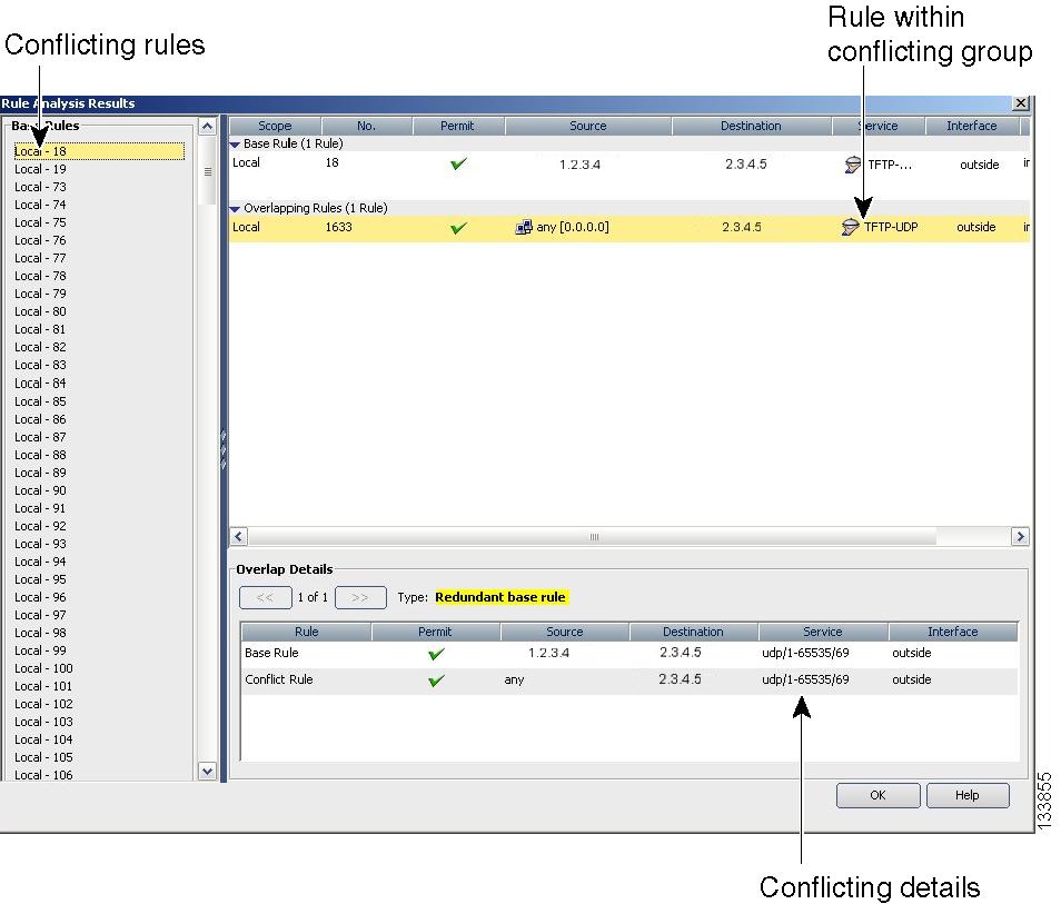
Tip ![]() In addition to analysis, you can use the Combine Rules tool to have Security Manager evaluate your rules and find ways to combine them into more efficient rules. For more information, see Combining Rules.
In addition to analysis, you can use the Combine Rules tool to have Security Manager evaluate your rules and find ways to combine them into more efficient rules. For more information, see Combining Rules.
Related Topics
•![]() Understanding Device Specific Access Rule Behavior
Understanding Device Specific Access Rule Behavior
•![]() Understanding Access Rule Address Requirements and How Rules Are Deployed
Understanding Access Rule Address Requirements and How Rules Are Deployed
Step 1 ![]() Do one of the following:
Do one of the following:
•![]() (Device view) Select Firewall > Access Rules from the Policy selector.
(Device view) Select Firewall > Access Rules from the Policy selector.
•![]() (Policy view) Select Firewall > Access Rules from the Policy Type selector. Select an existing policy or create a new one.
(Policy view) Select Firewall > Access Rules from the Policy Type selector. Select an existing policy or create a new one.
This opens the Access Rules Page, page I-9.
Step 2 ![]() Click the Tools button and select Analysis.
Click the Tools button and select Analysis.
The rules are analyzed and the results presented in the Rule Analysis Results Page, page I-93.
The report has three window panes.
•![]() Left pane—Lists conflicting groups of rules identified by the base rule, which is the rule with the lowest rule number.
Left pane—Lists conflicting groups of rules identified by the base rule, which is the rule with the lowest rule number.
•![]() Top right pane—Shows the base rule and all of the rules that conflict with it.
Top right pane—Shows the base rule and all of the rules that conflict with it.
•![]() Bottom right pane—Shows a detailed comparison between the base rule and the overlapping rule selected in the top right pane. Conflicting elements are shown in bold text.
Bottom right pane—Shows a detailed comparison between the base rule and the overlapping rule selected in the top right pane. Conflicting elements are shown in bold text.
Generating Hit Count Reports
You can generate hit count reports to determine how often each rule in your access rule policy is matched to traffic. If an access rule is deployed as multiple access control entries (ACEs), for example, when you use interface roles to define rules and the roles apply to more than one interface, you can see the separate hit count information for each ACE deployed. The hit count results do not show counts for any other type of ACL (for example, those used with class maps or AAA rules).
Use the hit count information to help you debug your access rules. The information can help you identify rules that are never hit (which might mean you do not need them, or that they are duplicates of rules higher in the ACL), and rules that are hit often (which means you might want to refine the rules).
The following figures show an example of a hit count report and how to use the information.
•![]() Figure 11-5 shows the default view. The upper table lists the rules as they exist in your access rules policy, either all rules or just the ones you selected before generating the report. When you select a rule, the ACEs created on the device for that rule are listed in the expanded table in the lower half of the window. When you initially open the report, the expanded table shows the ACEs for all policies listed in the upper table.
Figure 11-5 shows the default view. The upper table lists the rules as they exist in your access rules policy, either all rules or just the ones you selected before generating the report. When you select a rule, the ACEs created on the device for that rule are listed in the expanded table in the lower half of the window. When you initially open the report, the expanded table shows the ACEs for all policies listed in the upper table.
Hit counts in the expanded table are for each ACE, whereas the count in the rules table is the sum of the hit counts for all ACEs created by the rule.
•![]() Figure 11-6 shows the same ACEs except in CLI format. These are the ACEs as they exist in the device configuration.
Figure 11-6 shows the same ACEs except in CLI format. These are the ACEs as they exist in the device configuration.
For more information about how to read and interpret hit count reports, see Hit Count Query Results Page, page I-101.
Figure 11-5 Expanded Table
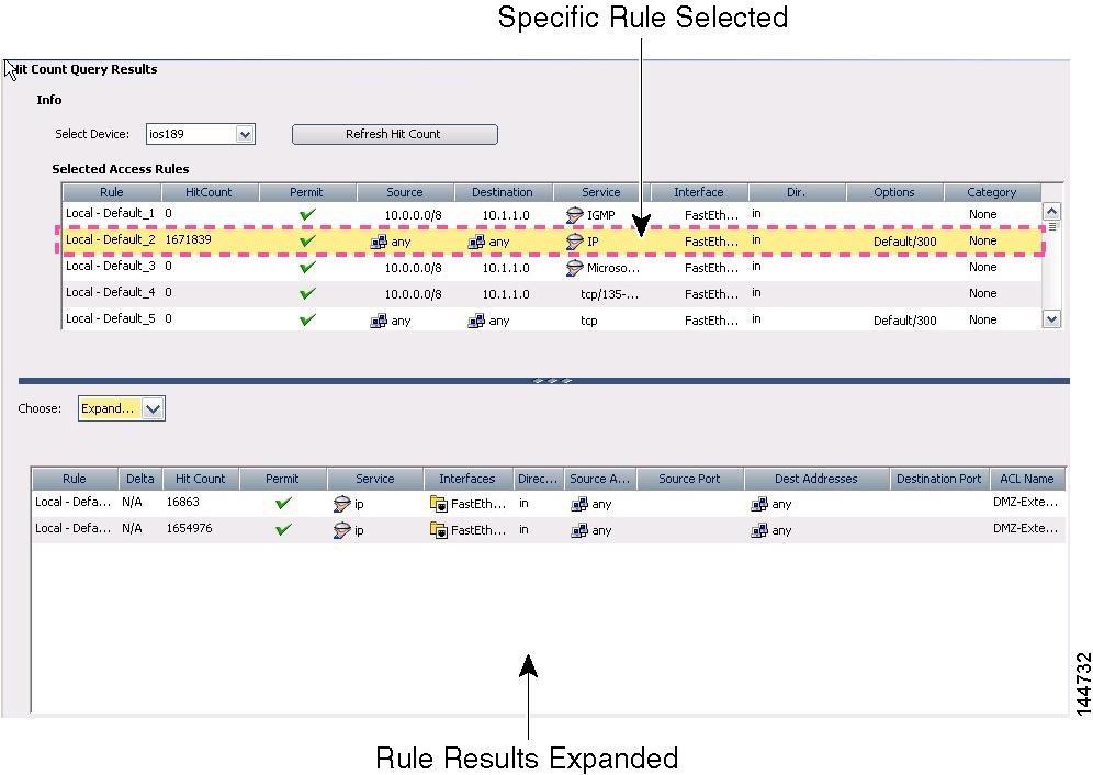
Figure 11-6 Raw ACE Table
Before You Begin
Hit count reports are device-specific. You can generate the report for a single device at a time from Device view only. Ensure that you deploy policies to the device before generating the reports.
Related Topics
Step 1 ![]() (Device view only.) Select Firewall > Access Rules to open the Access Rules Page, page I-9.
(Device view only.) Select Firewall > Access Rules to open the Access Rules Page, page I-9.
Step 2 ![]() If you want to get the hit count for specific rules, select them in the table. Use Shift+click to select a group of rules, or Ctrl+click to select multiple individual rules.
If you want to get the hit count for specific rules, select them in the table. Use Shift+click to select a group of rules, or Ctrl+click to select multiple individual rules.
You can also select rules by selecting a section heading, a scope heading, or by creating a filter to display only those rules that interest you.
Step 3 ![]() Click the Tools button located below the table, then select Hit Count to open the Hit Count Selection Summary Dialog Box, page I-101.
Click the Tools button located below the table, then select Hit Count to open the Hit Count Selection Summary Dialog Box, page I-101.
Step 4 ![]() Select the rules to include in the report. Select All Rules to include all local, shared, and inherited rules. If you selected rules before initiating the report, select that option.
Select the rules to include in the report. Select All Rules to include all local, shared, and inherited rules. If you selected rules before initiating the report, select that option.
Step 5 ![]() Click OK.
Click OK.
The tool obtains the ACL and hit count information from the device. You can abort the operation if you want. When the information is obtained, it is displayed in the Hit Count Query Results Page, page I-101.
You can click Refresh Hit Count while the report is open to obtain the latest information. The Delta column displays the difference in hit count since the last refresh.
Importing Rules
Typically, when you add a device to Security Manager, you discover policies from the device. This action populates your access rules policy with the access control entries (ACEs) from all active ACLs on the device.
If you find there are other ACLs that have ACEs you want included in your policy, you can define them directly in Security Manager.
Another alternative, however, is to import them by copying and pasting the CLI from a device running-configuration or by typing in the desire commands. By using the Import Rules wizard, you can quickly create all of the ACEs and associated policy objects from ACLs that you know already work. You might also want to use this method if you are more comfortable using CLI to define your rules.
Related Topics
•![]() Understanding Interface Role Objects, page 8-33
Understanding Interface Role Objects, page 8-33
Step 1 ![]() (Device view only) Select Firewall > Access Rules to open the Access Rules Page, page I-9.
(Device view only) Select Firewall > Access Rules to open the Access Rules Page, page I-9.
Step 2 ![]() Select the row after which you want to add the rules. The row must be within the Local scope. If you do not select a row, the rules are added at the end of the Local scope.
Select the row after which you want to add the rules. The row must be within the Local scope. If you do not select a row, the rules are added at the end of the Local scope.
Step 3 ![]() Click the Tools button and select Import Rules to start the wizard (see Import Rules Wizard—Enter Parameters Page, page I-94).
Click the Tools button and select Import Rules to start the wizard (see Import Rules Wizard—Enter Parameters Page, page I-94).
Step 4 ![]() Enter the CLI in running-configuration format appropriate for the type of device, and enter the interface or interface role to which you want the rules to apply. Also, select the traffic direction with respect to the interface. For examples of importable CLI, see Examples of Imported Rules.
Enter the CLI in running-configuration format appropriate for the type of device, and enter the interface or interface role to which you want the rules to apply. Also, select the traffic direction with respect to the interface. For examples of importable CLI, see Examples of Imported Rules.
Beside access control rules, you should also include the CLI for the following items if they are referred to by the rules:
•![]() Time range objects (the time-range command with its subcommands), which can create time range policy objects.
Time range objects (the time-range command with its subcommands), which can create time range policy objects.
•![]() Object groups for PIX, ASA, and FWSM devices only (the object-group command with its subcommands), which can create network/host policy objects.
Object groups for PIX, ASA, and FWSM devices only (the object-group command with its subcommands), which can create network/host policy objects.
You are prompted if your CLI contains errors when you click the Next button. For some detailed tips about what you can enter, see Import Rules Wizard—Enter Parameters Page, page I-94.
Step 5 ![]() Click Next to process the rules and open the Import Rules Wizard—Status Page, page I-95.
Click Next to process the rules and open the Import Rules Wizard—Status Page, page I-95.
The CLI is evaluated and if importable, you are told the types of objects that were created from the CLI.
Step 6 ![]() Click Finish to import the rules, or click Next to view the rules and objects on the Import Rules Wizard—Preview Page, page I-96.
Click Finish to import the rules, or click Next to view the rules and objects on the Import Rules Wizard—Preview Page, page I-96.
The information on the Preview page is read-only. If the rules are acceptable, click Finish. If you want to make changes, you can edit them in the access rules policy.
Examples of Imported Rules
The following are some examples of CLI that you can import and the rules and policy objects that are created from them. For information on how to import rules, see Importing Rules.
Example 1: Restrict a network from accessing FTP servers (ASA devices)
The following access list uses object groups and restricts the 10.200.10.0/24 network from accessing some FTP servers. All other traffic is allowed.
object-group network ftp_servers
network-object host 172.16.56.195
network-object 192.168.1.0 255.255.255.224
access-list ACL_IN extended deny tcp 10.200.10.0 255.255.255.0 object-group ftp_servers
access-list ACL_IN extended permit ip any any
This example creates a network/host object named ftp_servers and two access rules.
Example 2: Restrict web access during working hours (ASA devices)
The following example denies HTTP requests between the hours of 8 AM and 6 PM, which are typical work hours.
time-range no-http
periodic weekdays 8:00 to 18:00
access-list 101 deny tcp any any eq www time-range no-http
This example creates a time range object named no-http and one access rule.

Example 3: Filtering on TCP and ICMP using port numbers (IOS devices)
In the following example, the first line of the extended access list named goodports permits any incoming TCP connections with destination ports greater than 1023. The second line permits incoming TCP connections to the Simple Mail Transfer Protocol (SMTP) port of host 172.28.1.2. The last line permits incoming ICMP messages for error feedback.
ip access-list extended goodports
permit tcp any 172.28.0.0 0.0.255.255 gt 1023
permit tcp any host 172.28.1.2 eq 25
permit icmp any 172.28.0.0 255.255.255.255
This example creates three access rules. Notice that the wildcard masks used in the IOS ACL syntax are converted to regular subnet masks. Security Manager automatically converts between standard network/host subnet mask designations and the wildcard masks required in IOS ACLs. Because ASA/PIX/FWSM requires the use of subnet masks in ACL commands, this makes it possible for you to create rules that can apply to all devices; Security Manager takes care of converting your rules to the correct syntax.
Example 4: Standard ACLs restricting hosts (IOS devices)
In the following example, the workstation belonging to Jones is allowed access to Ethernet interface 0 and the workstation belonging to Smith is not allowed access:
ip access-list standard workstations
remark Permit only Jones workstation through
permit 172.16.2.88
remark Do not allow Smith workstation through
deny 172.16.3.13
This example creates two rules, converting the standard rules to extended rules (to any destination). The remarks are saved in the description field.
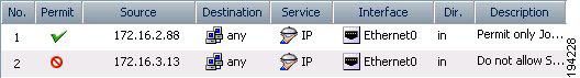
For more examples of ACLs in command language format, see the following:
•![]() IOS Devices—http://www.cisco.com/en/US/docs/ios/sec_data_plane/configuration/guide/sec_create_IP_apply.html#wp1027258.
IOS Devices—http://www.cisco.com/en/US/docs/ios/sec_data_plane/configuration/guide/sec_create_IP_apply.html#wp1027258.
•![]() ASA Devices—http://www.cisco.com/en/US/docs/security/asa/asa82/configuration/guide/acl_extended.html.
ASA Devices—http://www.cisco.com/en/US/docs/security/asa/asa82/configuration/guide/acl_extended.html.
Optimizing Access Rules Automatically During Deployment
You can configure the system to optimize the access control lists (ACLs) that are created from your access rules policies when they are deployed to specific devices or to all devices. This optimization affects only the deployed policies, it does not make any changes to your access rules policy.
Optimization removes redundancies and conflicts and can combine multiple entries (ACEs) into single entries. Although the order of entries might change, the semantics of your policies are preserved; the optimized ACL accepts or denies the same set of packets as did its unoptimized form. Following are the basic cases where changes are made:
•![]() Ineffective ACE—Where one entry is a subset of, or equal to, another entry, the ineffective ACE is removed. Consider the following example:
Ineffective ACE—Where one entry is a subset of, or equal to, another entry, the ineffective ACE is removed. Consider the following example:
access-list acl_mdc_inside_access deny ip host 10.2.1.1 any
access-list acl_mdc_inside_access deny ip 10.2.1.0 255.255.255.0 any
The first ACE is actually a subset of the second ACE. ACL optimization will deploy only the second entry.
•![]() Superset ACE—Where one entry is a superset of another and the order of the rules does not matter, the redundant rule is removed. Consider the following example:
Superset ACE—Where one entry is a superset of another and the order of the rules does not matter, the redundant rule is removed. Consider the following example:
access-list acl_mdc_inside_access permit tcp any any range 110 120
access-list acl_mdc_inside_access deny tcp any any range 115
The second ACE will never be hit. ACL optimization will remove the second ACE and deploy only the first one.
•![]() Adjacent ACEs—Where two entries are similar enough that a single entry can do the same job. There can be no intervening rules that change which packets will hit each rule. Consider the following example:
Adjacent ACEs—Where two entries are similar enough that a single entry can do the same job. There can be no intervening rules that change which packets will hit each rule. Consider the following example:
access-list myacl permit ip 1.1.1.0 255.255.255.128 any
access-list myacl permit ip 1.1.1.128 255.255.255.128 any
The two ACEs are merged into one: access-list myacl permit ip 1.1.1.0 255.255.255.0 any.
By configuring ACL deployment optimization, you can create smaller ACLs that are more efficient, which can improve performance on devices with limited, non-expandable memory, such as the FWSM, which can be shared among multiple virtual contexts.
However, there are down sides to configuring ACL deployment optimization:
•![]() Because optimization changes what would normally be deployed for your access rules, it is hard to correlate those rules to the actual deployed ACEs. This can make the results of the hit count tool unusable, and make it very difficult to correlate events in the Cisco Security Monitoring, Analysis and Response System application. If it is important to you that you can monitor your access rules using these tools, do not enable optimization. For more information, see Generating Hit Count Reports, Viewing CS-MARS Events for an Access Rule, page 20-25, and About Querying for Access Rule Events, page 20-24.
Because optimization changes what would normally be deployed for your access rules, it is hard to correlate those rules to the actual deployed ACEs. This can make the results of the hit count tool unusable, and make it very difficult to correlate events in the Cisco Security Monitoring, Analysis and Response System application. If it is important to you that you can monitor your access rules using these tools, do not enable optimization. For more information, see Generating Hit Count Reports, Viewing CS-MARS Events for an Access Rule, page 20-25, and About Querying for Access Rule Events, page 20-24.
•![]() Optimization does not address inherent problems in your access rules policy. It is typically better to address redundancies and conflicts proactively by using the rule analysis tool (see Generating Analysis Reports). You can also use the combine rules tool to optimize your rules in the access rules policy before you deploy them (see Combining Rules).
Optimization does not address inherent problems in your access rules policy. It is typically better to address redundancies and conflicts proactively by using the rule analysis tool (see Generating Analysis Reports). You can also use the combine rules tool to optimize your rules in the access rules policy before you deploy them (see Combining Rules).
If you decide to configure ACL deployment optimization, consider enabling it only for those devices that are memory constrained.
Step 1 ![]() Log into Windows on the Security Manager server.
Log into Windows on the Security Manager server.
Step 2 ![]() Use a text editor such as NotePad to open the C:\Program Files\CSCOpx\MDC\athena\config\csm.properties file. Locate the optimization section and read the instructions.
Use a text editor such as NotePad to open the C:\Program Files\CSCOpx\MDC\athena\config\csm.properties file. Locate the optimization section and read the instructions.
•![]() To turn on full optimization for all devices, enter the following:
To turn on full optimization for all devices, enter the following:
OPTIMIZE.*=full
•![]() To turn on full optimization for a specific device, replace the asterisk with the Security Manager display name for the device. For example, if the display name is west_coast.cisco.com, enter the following:
To turn on full optimization for a specific device, replace the asterisk with the Security Manager display name for the device. For example, if the display name is west_coast.cisco.com, enter the following:
OPTIMIZE.west_coast.cisco.com=full
•![]() To turn on optimization but preserve the object groups used in the ACE, replace the full keyword with preserve_og. For example:
To turn on optimization but preserve the object groups used in the ACE, replace the full keyword with preserve_og. For example:
OPTIMIZE.west_coast.cisco.com=preserve_og
•![]() If you do not want to allow the merger of adjacent entries, enter the following:
If you do not want to allow the merger of adjacent entries, enter the following:
AclOptimization.doMerge=false
Step 3 ![]() Save the file. The settings take effect immediately and will be applied to all subsequent deployment jobs.
Save the file. The settings take effect immediately and will be applied to all subsequent deployment jobs.
You can generate optimization reports for deployment jobs by selecting Capture Discovery/Deployment Debugging Snapshots to File, which is located in Tools > Security Manager Administration > Debug Options.
The deployment results will show optimization results summarized as an informational message that includes the original number of ACEs before optimization and the number of ACEs after optimization. The results are saved to a file on the server in the C:\Program Files\CSCOpx\MDC\temp folder. A job ID is used as part of the filename.
Working with Inspection Rules
When you configure inspection rules on appliances running ASA/PIX 7.0, access-list, policy-map/class-map commands are generated.
When you configure inspection rules on FWSMs and PIX 6.3 devices, fixup commands are generated.
When you configure inspection rules on routers running IOS 12.3 and later,ip-inspect commands are generated.
The following topics will help you work with inspection rules:
•![]() Moving Rules and the Importance of Rule Order
Moving Rules and the Importance of Rule Order
•![]() Understanding Inspection Rules
Understanding Inspection Rules
•![]() Configuring Settings for Inspection Rules for IOS Devices
Configuring Settings for Inspection Rules for IOS Devices
•![]() Inspection Rules Page, page I-16
Inspection Rules Page, page I-16
Understanding Inspection Rules
Inspection rules provide an informational list of services, protocols, and port numbers to which a firewall device applies the Adaptive Security Algorithm (ASA). The default ports or those you specify are the ports at which the device listens for each service.
The default configuration of the firewall device includes a set of application inspection entries that associate supported protocols with specific TCP or UDP port numbers and that identify any special handling required. The inspection function does not support NAT or PAT for certain applications because of the constraints imposed by the applications. You can change the port assignments for some applications, but other applications have fixed port assignments that you cannot change.
You can extend the HTTP inspection capabilities to select which HTTP methods defined in the RFC to permit in HTTP traffic. If the device encounters an HTTP method not permitted, it drops the packet and closes the connection to prevent any subsequent data from traversing the security appliance.
Inspection rules are based on Context-Based Access Control (CBAC) to intelligently filter TCP and UDP packets based on application-layer protocol session information. You can configure CBAC to permit specified TCP and UDP traffic through a firewall only when the connection is initiated from within the network you want to protect. CBAC can inspect traffic for sessions that originate from either side of the firewall, and CBAC can be used for intranet, extranet, and Internet perimeters of your network.
When configuring inspection rules, you should:
1. ![]() Populate the Inspection Rules table with device, service, and traffic direction information. To access the Inspection Rules table, select Firewall > Inspection Rules.
Populate the Inspection Rules table with device, service, and traffic direction information. To access the Inspection Rules table, select Firewall > Inspection Rules.
2. ![]() (For IOS devices) Configure settings for deeper packet inspection. To access settings for inspection rules, select Firewall > Settings > Inspection.
(For IOS devices) Configure settings for deeper packet inspection. To access settings for inspection rules, select Firewall > Settings > Inspection.
From the Inspection Rules tables, you can generate Policy Query reports to help you identify all rules in the global policy that could affect the defined packets. For more information, see Generating Policy Query Reports.
Related Topics
•![]() Working with Inspection Rules
Working with Inspection Rules
•![]() Supported Features for Inspection
Supported Features for Inspection
Supported Features for Inspection
Table 11-1 shows how platforms managed by Security Manager support inspection and fixup.
Related Topics
•![]() Understanding Inspection Rules
Understanding Inspection Rules
•![]() Working with Inspection Rules
Working with Inspection Rules
Adding Inspection Rules
When adding an inspection rule, you can perform packet inspection globally or on a per-interface basis and identify traffic direction. You can constrain the inspection further based on other criteria that differs depending on the platform for which the rule inspected.
A branching wizard is used to help you configure inspection rules. Basically, the steps in the wizard are the same for all platforms; however, the dialog boxes in the wizard will vary depending on your selections.
This procedure assumes you are adding a rule from Device view. To add a rule from Policy view, see Creating a New Shared Policy, page 6-39, then complete this procedure. After you complete the procedure, you can share the global policy and assign devices to it. For more information, see Modifying Policy Assignments in Policy View, page 6-39.
The following procedure describes how to add an inspection rule.
Related Topics
•![]() Add and Edit Inspection Rule Dialog Boxes, page I-18
Add and Edit Inspection Rule Dialog Boxes, page I-18
•![]() Configuring Default Protocol Ports
Configuring Default Protocol Ports
•![]() Configuring Custom Destination Ports
Configuring Custom Destination Ports
•![]() Configuring Destination Address and Port (IOS)
Configuring Destination Address and Port (IOS)
•![]() Configuring Source and Destination Address and Port (ASA, FWSM 3.x)
Configuring Source and Destination Address and Port (ASA, FWSM 3.x)
Step 1 ![]() Select a device from the Device selector.
Select a device from the Device selector.
Step 2 ![]() Select Firewall > Inspection Rules.
Select Firewall > Inspection Rules.
The Inspection Rules page appears. For a description of the GUI elements, see Table I-9 on page I-16.
Step 3 ![]() Right-click inside the table, then click Add Row. You can also use the shortcut keys (Ctrl+R).
Right-click inside the table, then click Add Row. You can also use the shortcut keys (Ctrl+R).
The Add Inspection Rule page appears. For a description of the GUI elements, see Table I-10 on page I-19.
Step 4 ![]() Select the Enable Rule check box, which, when selected, indicates that the rule appears after the configuration is generated.
Select the Enable Rule check box, which, when selected, indicates that the rule appears after the configuration is generated.
Step 5 ![]() Identify whether the rule is global or per interface.
Identify whether the rule is global or per interface.
•![]() For PIX platforms, rules are defined globally. Go to Step 8.
For PIX platforms, rules are defined globally. Go to Step 8.
•![]() For ASA platforms, rules are defined either globally or per interface.
For ASA platforms, rules are defined either globally or per interface.
–![]() If per interface, go to Step 6.
If per interface, go to Step 6.
–![]() If globally, go to Step 8.
If globally, go to Step 8.
•![]() For IOS platforms, rules are defined per interface. Go to Step 7.
For IOS platforms, rules are defined per interface. Go to Step 7.
•![]() For FWSM platforms, rules are defined globally. Go to Step 8.
For FWSM platforms, rules are defined globally. Go to Step 8.
Step 6 ![]() If the rule is per interface, select the traffic direction, which identifies traffic direction within a network.
If the rule is per interface, select the traffic direction, which identifies traffic direction within a network.
Step 7 ![]() To enter interface information, click Edit to open the Edit Interfaces dialog box. Enter interface information, or click Select, which opens the Object Selector dialog box from which to make your selection. The interface identifies the logical name of the interface (interface role) or physical interface to which a rule is assigned. If you are using the Object Selector dialog box, do one of the following, then click OK :
To enter interface information, click Edit to open the Edit Interfaces dialog box. Enter interface information, or click Select, which opens the Object Selector dialog box from which to make your selection. The interface identifies the logical name of the interface (interface role) or physical interface to which a rule is assigned. If you are using the Object Selector dialog box, do one of the following, then click OK :
•![]() Select from the list of available objects, then click >>.
Select from the list of available objects, then click >>.
The objects are moved to the selected column.
•![]() Click Add to create a new interface role object.
Click Add to create a new interface role object.
A popup window helps you define the object. After you complete the definition, the new object is listed in the selected column.
For more information, see Understanding Interface Role Objects, page 8-33.
Step 8 ![]() Select the matched traffic criteria. Depending on your selection, the wizard pages will vary.
Select the matched traffic criteria. Depending on your selection, the wizard pages will vary.
•![]() Default Protocol Ports. See Configuring Default Protocol Ports. You can also limit inspection between source and destination IP address for ASA platforms. See Configuring Source and Destination Address and Port (ASA, FWSM 3.x).
Default Protocol Ports. See Configuring Default Protocol Ports. You can also limit inspection between source and destination IP address for ASA platforms. See Configuring Source and Destination Address and Port (ASA, FWSM 3.x).
•![]() Custom Destination Ports. See Configuring Custom Destination Ports.
Custom Destination Ports. See Configuring Custom Destination Ports.
•![]() Destination Address and Port (IOS). See Configuring Destination Address and Port (IOS).
Destination Address and Port (IOS). See Configuring Destination Address and Port (IOS).
•![]() Source and Destination Address and Port (ASA). See Configuring Source and Destination Address and Port (ASA, FWSM 3.x).
Source and Destination Address and Port (ASA). See Configuring Source and Destination Address and Port (ASA, FWSM 3.x).
Note ![]() For FWSM 2.x and PIX 6.3(x), you must select the matched traffic criteria as either Default Inspection Traffic or TCP or UDP Destination Ports. If the latter is selected, the protocol selection must be "any".
For FWSM 2.x and PIX 6.3(x), you must select the matched traffic criteria as either Default Inspection Traffic or TCP or UDP Destination Ports. If the latter is selected, the protocol selection must be "any".
Step 9 ![]() (Optional) Under Category, select a category to help you identify this rule in the table. See Using Category Objects, page 8-6.
(Optional) Under Category, select a category to help you identify this rule in the table. See Using Category Objects, page 8-6.
Step 10 ![]() (Optional) Enter a description to help you identify the rule.
(Optional) Enter a description to help you identify the rule.
Step 11 ![]() Click Next.
Click Next.
The appropriate wizard guides you through the configuration.
Configuring Default Protocol Ports
This procedure assumes you selected Default Protocol Ports as the type of traffic matched for inspection rules. This option configures default inspection traffic.
Related Topics
•![]() Copying Policies Between Devices, page 6-22
Copying Policies Between Devices, page 6-22
•![]() Working with Shared Policies in Device View, page 6-25
Working with Shared Policies in Device View, page 6-25
Step 1 ![]() To limit inspection between the source and destination, select the check box, then complete the procedure for configuring source and destination IP addresses. (See Configuring Source and Destination Address and Port (ASA, FWSM 3.x).) Otherwise, click Next.
To limit inspection between the source and destination, select the check box, then complete the procedure for configuring source and destination IP addresses. (See Configuring Source and Destination Address and Port (ASA, FWSM 3.x).) Otherwise, click Next.
The wizard page listing protocols appears.
Step 2 ![]() Select a protocol to inspect. Certain protocols enable you to configure additional information. For those protocols, click Configure, then complete the respective popup window. For more information, see Add Inspect/Application FW Rule Wizard Inspected Protocol Page and Edit Inspected Protocol Dialog Boxes, page I-21.
Select a protocol to inspect. Certain protocols enable you to configure additional information. For those protocols, click Configure, then complete the respective popup window. For more information, see Add Inspect/Application FW Rule Wizard Inspected Protocol Page and Edit Inspected Protocol Dialog Boxes, page I-21.
Step 3 ![]() Click Finish.
Click Finish.
The dialog box closes and you return to the Inspection Rules table with the new information displayed.
Configuring Custom Destination Ports
This procedure assumes you selected Custom Destination Ports as the type of traffic matched for inspection rules (IOS). This option configures TCP and UDP.
Related Topics
•![]() Match Traffic by Custom Destination Ports Page, page I-25
Match Traffic by Custom Destination Ports Page, page I-25
•![]() Copying Policies Between Devices, page 6-22
Copying Policies Between Devices, page 6-22
•![]() Working with Shared Policies in Device View, page 6-25
Working with Shared Policies in Device View, page 6-25
Step 1 ![]() Select the protocol.
Select the protocol.
Step 2 ![]() Enter port information.
Enter port information.
Step 3 ![]() Click Next.
Click Next.
The page listing protocols appears.
Step 4 ![]() Select a protocol to inspect. Certain protocols enable you to configure additional information. For those protocols, click Configure and complete the respective popup window. For a description of the GUI elements, see Table I-11 on page I-21.
Select a protocol to inspect. Certain protocols enable you to configure additional information. For those protocols, click Configure and complete the respective popup window. For a description of the GUI elements, see Table I-11 on page I-21.
Step 5 ![]() To enable additional IOS settings, click Enable. Otherwise, go to Step 8.
To enable additional IOS settings, click Enable. Otherwise, go to Step 8.
Step 6 ![]() Do any of the following:
Do any of the following:
•![]() Click Enable Alert Messages, which, when selected, enables Context-based Access Control (CBAC) alert messages, which are displayed on the console.
Click Enable Alert Messages, which, when selected, enables Context-based Access Control (CBAC) alert messages, which are displayed on the console.
•![]() Click Enable Audit Trail Messages, which, when selected, shows Context-based Access Control (CBAC) audit trail messages, which are displayed after each CBAC session closes.
Click Enable Audit Trail Messages, which, when selected, shows Context-based Access Control (CBAC) audit trail messages, which are displayed after each CBAC session closes.
Step 7 ![]() Enter a timeout value. Values are 5-43200.
Enter a timeout value. Values are 5-43200.
Step 8 ![]() Click Finish.
Click Finish.
The dialog box closes, and you return to the Inspection Rules table with the new rule information displayed.
Configuring Destination Address and Port (IOS)
This procedure assumes you selected Destination IP Address (IOS) as the type of traffic matched for inspection rules.
Related Topics
•![]() Match Traffic by Destination Address and Port (IOS) Page, page I-25
Match Traffic by Destination Address and Port (IOS) Page, page I-25
•![]() Copying Policies Between Devices, page 6-22
Copying Policies Between Devices, page 6-22
•![]() Working with Shared Policies in Device View, page 6-25
Working with Shared Policies in Device View, page 6-25
Step 1 ![]() Enter the destination addresses or click Select, which opens the Object Selector dialog box from which to make your selection. If the latter, do one of the following, then click OK :
Enter the destination addresses or click Select, which opens the Object Selector dialog box from which to make your selection. If the latter, do one of the following, then click OK :
•![]() Select from the list of available objects, then click >>.
Select from the list of available objects, then click >>.
The objects are moved to the selected column.
•![]() Click the Add button to create a new network object or interface role object to use as a destination address.
Click the Add button to create a new network object or interface role object to use as a destination address.
A popup window helps you define the object. After you complete the definition, the new object is listed in the selected column.
For more information, see:
•![]() Understanding Network/Host Objects, page 8-65
Understanding Network/Host Objects, page 8-65
•![]() Understanding Interface Role Objects, page 8-33
Understanding Interface Role Objects, page 8-33
Step 2 ![]() Enter protocol information.
Enter protocol information.
Step 3 ![]() Enter port information.
Enter port information.
Step 4 ![]() Click Next.
Click Next.
The page listing protocols appears.
Step 5 ![]() Select a protocol to inspect. Certain protocols enable you to configure additional information. For those protocols, click Configure and complete the respective popup window. For a description of the GUI elements, see Table I-11 on page I-21.
Select a protocol to inspect. Certain protocols enable you to configure additional information. For those protocols, click Configure and complete the respective popup window. For a description of the GUI elements, see Table I-11 on page I-21.
Step 6 ![]() Click Finish.
Click Finish.
The dialog box closes and you return to the Inspection Rules table with the new information displayed.
Configuring Source and Destination Address and Port (ASA, FWSM 3.x)
This procedure assumes you selected Source and Destination Address and Port (ASA, FWSM 3.x) as the type of traffic matched for inspection rules.
Related Topics
•![]() Match Traffic by Source and Destination Address and Port (ASA, FWSM 3.x) Page, page I-27
Match Traffic by Source and Destination Address and Port (ASA, FWSM 3.x) Page, page I-27
•![]() Copying Policies Between Devices, page 6-22
Copying Policies Between Devices, page 6-22
•![]() Working with Shared Policies in Device View, page 6-25
Working with Shared Policies in Device View, page 6-25
Step 1 ![]() Select whether to permit or deny traffic.
Select whether to permit or deny traffic.
Step 2 ![]() Enter the source addresses or click Select, which opens the Object Selector dialog box from which to make your selection. If the latter, select whether the source type is a network or interface role, then do one of the following, then click OK:
Enter the source addresses or click Select, which opens the Object Selector dialog box from which to make your selection. If the latter, select whether the source type is a network or interface role, then do one of the following, then click OK:
•![]() Select from the list of available objects, then click >>.
Select from the list of available objects, then click >>.
The objects are moved to the selected column.
•![]() Click Add to create a new network object or interface role object to use as a source address.
Click Add to create a new network object or interface role object to use as a source address.
A popup window helps you define the object. After you complete the definition, the new object is listed in the selected column.
For more information, see:
•![]() Understanding Network/Host Objects, page 8-65
Understanding Network/Host Objects, page 8-65
•![]() Understanding Interface Role Objects, page 8-33
Understanding Interface Role Objects, page 8-33
Step 3 ![]() Enter the destination addresses or click Select, which opens the Object Selector dialog box from which to make your selection. If the latter, select whether the destination type is a network or interface role, then do one of the following, then click OK:
Enter the destination addresses or click Select, which opens the Object Selector dialog box from which to make your selection. If the latter, select whether the destination type is a network or interface role, then do one of the following, then click OK:
•![]() Select from the list of available objects, then click >>.
Select from the list of available objects, then click >>.
The objects are moved to the selected column.
•![]() Click Add to create a new network object or interface role object to use as a destination address.
Click Add to create a new network object or interface role object to use as a destination address.
A popup window helps you define the object. After you complete the definition, the new object is listed in the selected column.
For more information, see:
•![]() Understanding Network/Host Objects, page 8-65
Understanding Network/Host Objects, page 8-65
•![]() Understanding Interface Role Objects, page 8-33
Understanding Interface Role Objects, page 8-33
Step 4 ![]() Enter the services or click Select, which opens the Object Selector dialog box from which to make your selection. If the latter, do one of the following, then click OK :
Enter the services or click Select, which opens the Object Selector dialog box from which to make your selection. If the latter, do one of the following, then click OK :
•![]() Select from the list of available objects, then click >>.
Select from the list of available objects, then click >>.
The objects are moved to the selected column.
•![]() Click Add to create a new service object.
Click Add to create a new service object.
A popup window helps you define the object. After you complete the definition, the new object is listed in the selected column.
For more information, see Understanding and Specifying Services and Service and Port List Objects, page 8-75.
Step 5 ![]() Enter a time range, which identifies when the rules are enforced. For more information, see Creating Time Range Objects, page 8-92.
Enter a time range, which identifies when the rules are enforced. For more information, see Creating Time Range Objects, page 8-92.
Step 6 ![]() Click Next.
Click Next.
The page listing protocols appears.
Step 7 ![]() Select a protocol to inspect. Certain protocols enable you to configure additional information. For those protocols, click Configure and complete the respective popup window. For a description of the GUI elements, see Table I-11 on page I-21.
Select a protocol to inspect. Certain protocols enable you to configure additional information. For those protocols, click Configure and complete the respective popup window. For a description of the GUI elements, see Table I-11 on page I-21.
Step 8 ![]() Click Finish.
Click Finish.
The dialog box closes and you return to the Inspection Rules table with the new information displayed.
Configuring Settings for Inspection Rules for IOS Devices
If you configure inspection rules, you can also configure inspection settings to change the default settings for some global inspection parameters. Most of the inspection settings relate to preventing or mitigating Denial of Service attacks. The default settings for most of these options are appropriate for most networks, so configure this policy only if you need to adjust one or more settings.
Related Topics
Step 1 ![]() Do one of the following to open the Inspection Settings Page, page I-70:
Do one of the following to open the Inspection Settings Page, page I-70:
•![]() (Device view) Select Firewall > Settings > Inspection from the Policy selector.
(Device view) Select Firewall > Settings > Inspection from the Policy selector.
•![]() (Policy view) Select Firewall > Settings > Inspection from the Policy Type selector. Select an existing policy or create a new one.
(Policy view) Select Firewall > Settings > Inspection from the Policy Type selector. Select an existing policy or create a new one.
Step 2 ![]() Configure the settings whose default values you want to change. If you do not change a setting, it is not configured on the device (the default remains configured). For specific information on each setting, see Inspection Settings Page, page I-70.
Configure the settings whose default values you want to change. If you do not change a setting, it is not configured on the device (the default remains configured). For specific information on each setting, see Inspection Settings Page, page I-70.
Working with AAA Rules
Access control is the way to control who is allowed access to the network server and what services they are allowed to use once they have access. Authentication, authorization, and accounting (AAA) network security services provide the primary framework through which you set up access control on your firewall device or security appliance.
AAA rules control authentication (who the user is), authorization (what the user is allowed to do), and accounting (what the user did) for traffic.
When configuring AAA rules, you should:
1. ![]() Configure AAA rules to identify device, service, and traffic direction information. The AAA Rules page is used to define AAA rules for all platforms. To access the AAA Rules table, select Firewall > AAA Rules.
Configure AAA rules to identify device, service, and traffic direction information. The AAA Rules page is used to define AAA rules for all platforms. To access the AAA Rules table, select Firewall > AAA Rules.
2. ![]() Configure settings specific to PIX, ASA, and IOS devices. PIX and ASA devices support HTTPS, proxy, and MAC settings. IOS devices identify AAA servers, define banner information, and set timeout values. To access settings for AAA rules, select:
Configure settings specific to PIX, ASA, and IOS devices. PIX and ASA devices support HTTPS, proxy, and MAC settings. IOS devices identify AAA servers, define banner information, and set timeout values. To access settings for AAA rules, select:
a. ![]() Firewall > Settings > AAA Firewall (PIX/ASA/FWSM).
Firewall > Settings > AAA Firewall (PIX/ASA/FWSM).
b. ![]() Firewall > Settings > AuthProxy (IOS).
Firewall > Settings > AuthProxy (IOS).
From the AAA Rules tables, you can generate Policy Query reports to help you identify all rules in the global policy that could affect the defined packets. For more information, see Generating Policy Query Reports.
Topics to help you work with AAA Rules are:
•![]() Moving Rules and the Importance of Rule Order
Moving Rules and the Importance of Rule Order
Topics to help you work with Settings for AAA Rules are:
•![]() Configuring Settings for AAA Firewall (PIX/ASA/FWSM)
Configuring Settings for AAA Firewall (PIX/ASA/FWSM)
•![]() Configuring Settings for AAA (IOS)
Configuring Settings for AAA (IOS)
Adding AAA Rules
This procedure assumes you are adding a rule from Device view. To add a rule from Policy view, see Creating a New Shared Policy, page 6-39, then complete this procedure. After you complete the procedure, you can share the global policy and assign devices to it. For more information, see Modifying Policy Assignments in Policy View, page 6-39.
Related Topics
•![]() Copying Policies Between Devices, page 6-22
Copying Policies Between Devices, page 6-22
•![]() Working with Shared Policies in Device View, page 6-25
Working with Shared Policies in Device View, page 6-25
•![]() Add and Edit AAA Rules Dialog Boxes, page I-4
Add and Edit AAA Rules Dialog Boxes, page I-4
Step 1 ![]() Select a device from the Device selector.
Select a device from the Device selector.
Step 2 ![]() Select Firewall > AAA Rules.
Select Firewall > AAA Rules.
The AAA Rule page appears. For a description of the GUI elements, see Table I-1 on page I-2.
Step 3 ![]() Right-click inside the work area, then click Add Row. You can also use the shortcut keys (Ctrl+R).
Right-click inside the work area, then click Add Row. You can also use the shortcut keys (Ctrl+R).
The Add AAA Rule page appears. For a description of the GUI elements, see Table I-2 on page I-5.
Step 4 ![]() (Optional) Select Enable Rule, which, when selected, indicates that the rule appears after the configuration is generated.
(Optional) Select Enable Rule, which, when selected, indicates that the rule appears after the configuration is generated.
Step 5 ![]() Select whether the rule applies to any of the following:
Select whether the rule applies to any of the following:
•![]() Authentication—Supported on all platforms.
Authentication—Supported on all platforms.
•![]() Authorization—For PIX/ASA/FWSM platforms only.
Authorization—For PIX/ASA/FWSM platforms only.
•![]() Accounting—For PIX/ASA/FWSM platforms only.
Accounting—For PIX/ASA/FWSM platforms only.
Step 6 ![]() Select whether to permit or deny traffic for the rule you are defining.
Select whether to permit or deny traffic for the rule you are defining.
Step 7 ![]() Enter the source addresses or click Select, which opens the Object Selector dialog box from which to make your selection. If the latter, select whether the source type is a network or interface role, then do one of the following, then click OK :
Enter the source addresses or click Select, which opens the Object Selector dialog box from which to make your selection. If the latter, select whether the source type is a network or interface role, then do one of the following, then click OK :
•![]() Select from the list of available objects, then click >>.
Select from the list of available objects, then click >>.
The objects are moved to the selected column.
•![]() Click the Add button to create a new network object or interface role object to use as a source address.
Click the Add button to create a new network object or interface role object to use as a source address.
A popup window helps you define the object. After you complete the definition, the new object is listed in the selected column.
For more information, see:
•![]() Understanding Network/Host Objects, page 8-65
Understanding Network/Host Objects, page 8-65
•![]() Understanding Interface Role Objects, page 8-33
Understanding Interface Role Objects, page 8-33
Step 8 ![]() Enter the destination addresses or click Select, which opens the Object Selector dialog box from which to make your selection. If the latter, select whether the destination type is a network or interface role, then do one of the following, then click OK :
Enter the destination addresses or click Select, which opens the Object Selector dialog box from which to make your selection. If the latter, select whether the destination type is a network or interface role, then do one of the following, then click OK :
•![]() Select from the list of available objects, then click >>.
Select from the list of available objects, then click >>.
The objects are moved to the selected column.
•![]() Click the Add button to create a new network object or interface role object to use as a destination address.
Click the Add button to create a new network object or interface role object to use as a destination address.
A popup window helps you define the object. After you complete the definition, the new object is listed in the selected column.
For more information, see:
•![]() Understanding Network/Host Objects, page 8-65
Understanding Network/Host Objects, page 8-65
•![]() Understanding Interface Role Objects, page 8-33
Understanding Interface Role Objects, page 8-33
Step 9 ![]() Enter the services or click Select, which opens the Object Selector dialog box from which to make your selection. If the latter, do one of the following, then click OK :
Enter the services or click Select, which opens the Object Selector dialog box from which to make your selection. If the latter, do one of the following, then click OK :
•![]() Select from the list of available services, then click >>.
Select from the list of available services, then click >>.
The objects are moved to the selected column.
•![]() Click the Add button to create a new service object.
Click the Add button to create a new service object.
A popup window helps you define the object. After you complete the definition, the new object is listed in the selected column.
For more information, see Understanding and Specifying Services and Service and Port List Objects, page 8-75.
Step 10 ![]() Enter the AAA server group from the list or click Select, which opens the Object Selector dialog box from which to make your selection. If the latter, do one of the following, then click OK :
Enter the AAA server group from the list or click Select, which opens the Object Selector dialog box from which to make your selection. If the latter, do one of the following, then click OK :
•![]() Select from the list of available objects, then click >>.
Select from the list of available objects, then click >>.
The objects are moved to the selected column.
•![]() Click the Add button to create a new server group object.
Click the Add button to create a new server group object.
A popup window helps you define the object. After you complete the definition, the new object is listed in the selected column.
For more information, see Understanding AAA Server and Server Group Objects, page 8-15.
Step 11 ![]() Enter the interface information, or click Select, which opens the Object Selector dialog box from which to make your selection. The interface identifies the logical name of the interface (interface role) or physical interface to which a rule is assigned. If you are using the Object Selector dialog box, do one of the following, then click OK :
Enter the interface information, or click Select, which opens the Object Selector dialog box from which to make your selection. The interface identifies the logical name of the interface (interface role) or physical interface to which a rule is assigned. If you are using the Object Selector dialog box, do one of the following, then click OK :
•![]() Select from the list of available objects, then click >>.
Select from the list of available objects, then click >>.
The objects are moved to the selected column.
•![]() Click the Add button to create a new interface role object.
Click the Add button to create a new interface role object.
A popup window helps you define the object. After you complete the definition, the new object is listed in the selected column.
For more information, see Understanding Interface Role Objects, page 8-33.
Step 12 ![]() (Optional) Under Category, select a category to help you identify this rule in the table. See Using Category Objects, page 8-6.
(Optional) Under Category, select a category to help you identify this rule in the table. See Using Category Objects, page 8-6.
Step 13 ![]() (Optional) Enter a description to help you identify the rule.
(Optional) Enter a description to help you identify the rule.
Step 14 ![]() (For IOS devices only) Select the authentication proxy methods.
(For IOS devices only) Select the authentication proxy methods.
Step 15 ![]() Click OK.
Click OK.
The page closes and you return to the AAA table. The rule information is shown in the table.
Configuring Settings for AAA
Configuring settings for AAA enables you to configure added granularity when you are using AAA servers.
•![]() Settings for PIX/ASA/FWSM devices configures HTTPS, proxy, and MAC settings. For more information, see Configuring Settings for AAA Firewall (PIX/ASA/FWSM).
Settings for PIX/ASA/FWSM devices configures HTTPS, proxy, and MAC settings. For more information, see Configuring Settings for AAA Firewall (PIX/ASA/FWSM).
•![]() Settings for IOS devices identifies AAA servers, defines banner information, and sets timeout values. For more information, see Configuring Settings for AAA (IOS).
Settings for IOS devices identifies AAA servers, defines banner information, and sets timeout values. For more information, see Configuring Settings for AAA (IOS).
Configuring Settings for AAA Firewall (PIX/ASA/FWSM)
Before You Begin
Configure a AAA rule for the device or device group. For more information, see Adding AAA Rules.
Related Topics
•![]() Edit AAA Option Dialog Box, page I-7
Edit AAA Option Dialog Box, page I-7
•![]() Selecting Objects for Policies, page 8-2
Selecting Objects for Policies, page 8-2
Step 1 ![]() Select a device from the Device selector.
Select a device from the Device selector.
Step 2 ![]() Select Firewall > Settings > AAA Firewall.
Select Firewall > Settings > AAA Firewall.
The AAA Firewall page appears. The Advanced Setting tab is displayed by default. For a description of the GUI elements, see Table I-47 on page I-73.
Step 3 ![]() (Optional) Select Use Secure HTTP Authentication, which, when selected, requires additional user authentication during the session establishment.
(Optional) Select Use Secure HTTP Authentication, which, when selected, requires additional user authentication during the session establishment.
Step 4 ![]() (Optional) Select Enable Proxy Limit, then enter a value in the field provided.
(Optional) Select Enable Proxy Limit, then enter a value in the field provided.
Step 5 ![]() Decide whether to disable authentication challenge for FTP, HTTP, HTTPS, and Telnet protocols.
Decide whether to disable authentication challenge for FTP, HTTP, HTTPS, and Telnet protocols.
If you disable challenge authentication for a particular protocol, traffic using that protocol is allowed only if the traffic belongs to a session previously authenticated. This authentication can be accomplished by traffic using a protocol whose authentication challenge remains enabled. For example, if you disable challenge authentication for FTP, the FWSM denies new sessions using FTP if the traffic is included in an authentication rule. If you establish the session with a protocol whose authentication challenge is enabled (such as HTTP), FTP traffic is allowed.
Step 6 ![]() For ASA/PIX 7.2.2 and later devices, right-click inside the Interactive Authentication table, then select Add Row.
For ASA/PIX 7.2.2 and later devices, right-click inside the Interactive Authentication table, then select Add Row.
The Interactive Authentication Configuration dialog box appears. For a description of the GUI elements, see Table I-48 on page I-75
Step 7 ![]() Select the protocol that you want to listen for.
Select the protocol that you want to listen for.
Step 8 ![]() Identify the interface on which you enable listeners. Enter the interface information in the field provided or click Select, which opens the Interfaces Selector from which to make your selection. If the latter, do one of the following, then click OK:
Identify the interface on which you enable listeners. Enter the interface information in the field provided or click Select, which opens the Interfaces Selector from which to make your selection. If the latter, do one of the following, then click OK:
•![]() Select from the list of available objects, then click >>.
Select from the list of available objects, then click >>.
The objects are moved to the selected column.
•![]() Click the Add button to create a new object.
Click the Add button to create a new object.
A popup window helps you define the object. After you complete the definition, the new object is listed in the selected column.
Step 9 ![]() Identify the port number that the security appliance listens on; the defaults are 80 (HTTP) and 443 (HTTPS).
Identify the port number that the security appliance listens on; the defaults are 80 (HTTP) and 443 (HTTPS).
Step 10 ![]() (Optional) Select the check box, which, when enabled, redirects through traffic to an authentication web page served by the security appliance. Without the redirect keyword, only traffic directed to the security appliance interface can access the authentication web pages.
(Optional) Select the check box, which, when enabled, redirects through traffic to an authentication web page served by the security appliance. Without the redirect keyword, only traffic directed to the security appliance interface can access the authentication web pages.
Step 11 ![]() For FWSM devices, right-click inside the Clear Connections When Uauth Timer Expires table, then select Add Row.
For FWSM devices, right-click inside the Clear Connections When Uauth Timer Expires table, then select Add Row.
The Clear Connection Configuration dialog box appears. For a description of the GUI elements, see Table I-49 on page I-76.
Step 12 ![]() Enter the interface information or click Select, which opens the Interfaces Selector from which to make your selection. If the latter, do one of the following, then click OK:
Enter the interface information or click Select, which opens the Interfaces Selector from which to make your selection. If the latter, do one of the following, then click OK:
•![]() Select from the list of available objects, then click >>.
Select from the list of available objects, then click >>.
The objects are moved to the selected column.
•![]() Click the Add button to create a new object.
Click the Add button to create a new object.
A popup window helps you define the object. After you complete the definition, the new object is listed in the selected column.
Step 13 ![]() Enter the source address and netmask information or click Select, which opens the Networks/Hosts Selector from which to make your selection. If the latter, do one of the following, then click OK:
Enter the source address and netmask information or click Select, which opens the Networks/Hosts Selector from which to make your selection. If the latter, do one of the following, then click OK:
•![]() Select from the list of available objects, then click >>.
Select from the list of available objects, then click >>.
The objects are moved to the selected column.
•![]() Click the Add button to create a new object.
Click the Add button to create a new object.
A popup window helps you define the object. After you complete the definition, the new object is listed in the selected column.
Step 14 ![]() Click OK.
Click OK.
The dialog box closes and you return to the Advanced Setting page with the new information shown in the table.
Step 15 ![]() If you want to exempt some hosts from authentication and authorization, click the MAC Exempt List tab and configure the exemption list. Enter a name for the exemption list, and then click the Add Row button and fill in the Firewall AAA MAC Exempt Setting Dialog Box, page I-78.
If you want to exempt some hosts from authentication and authorization, click the MAC Exempt List tab and configure the exemption list. Enter a name for the exemption list, and then click the Add Row button and fill in the Firewall AAA MAC Exempt Setting Dialog Box, page I-78.
The order of entries matters, so ensure that any specific entries that are covered by broader entries come before the broad entries in the table. The device processes the list in order and the first match is applied to the host. For more detailed information about how the entries on the MAC exempt list are processed, see AAA Firewall Page, MAC-Exempt List Tab, page I-76.
Configuring Settings for AAA (IOS)
AuthProxy provides information about all authenticated-proxy user events for IOS devices.
This procedure assumes you are working from Device view.
Before You Begin
Configure a AAA rule for the device or device group. For more information, see Adding AAA Rules.
Related Topics
•![]() AuthProxy Timeout Tab (IOS), page I-81
AuthProxy Timeout Tab (IOS), page I-81
Step 1 ![]() Select a device from the Device selector.
Select a device from the Device selector.
Step 2 ![]() Select Firewall > Settings > AuthProxy.
Select Firewall > Settings > AuthProxy.
The AuthProxy page appears with the General tab displayed.
Step 3 ![]() Enter the authorization server groups or click Select, which opens the Object Selector dialog box from which to make your selection. If the latter, do one of the following, then click OK :
Enter the authorization server groups or click Select, which opens the Object Selector dialog box from which to make your selection. If the latter, do one of the following, then click OK :
•![]() Select from the list of available objects, then click >>.
Select from the list of available objects, then click >>.
The objects are moved to the selected column.
•![]() Click the Add button to create a new object.
Click the Add button to create a new object.
A popup window helps you define the object. After you complete the definition, the new object is listed in the selected column.
For more information, see Understanding AAA Server and Server Group Objects, page 8-15.
Step 4 ![]() Enter the accounting server groups or click Select, which opens the Object Selector dialog box from which to make your selection. If the latter, do one of the following, then click OK :
Enter the accounting server groups or click Select, which opens the Object Selector dialog box from which to make your selection. If the latter, do one of the following, then click OK :
•![]() Select from the list of available objects, then click >>.
Select from the list of available objects, then click >>.
The objects are moved to the selected column.
•![]() Click the Add button to create a new object.
Click the Add button to create a new object.
A popup window helps you define the object. After you complete the definition, the new object is listed in the selected column.
For more information, see Understanding AAA Server and Server Group Objects, page 8-15.
Step 5 ![]() (Optional) SelectUse Broadcast for Accounting, which, when enabled, sends accounting records to multiple AAA servers. Accounting records are simultaneously sent to the first server in each group. If the first server is unavailable, failover occurs using the backup servers defined within that group.
(Optional) SelectUse Broadcast for Accounting, which, when enabled, sends accounting records to multiple AAA servers. Accounting records are simultaneously sent to the first server in each group. If the first server is unavailable, failover occurs using the backup servers defined within that group.
Step 6 ![]() (Optional) Configure authentication server groups. Go to Platform > Device Admin > AAA.
(Optional) Configure authentication server groups. Go to Platform > Device Admin > AAA.
Step 7 ![]() Select the type of accounting notice.
Select the type of accounting notice.
•![]() Start-stop—Sends a start accounting notice at the beginning of a process and a stop accounting notice at the end of a process. The start accounting record is sent in the background. The requested user process begins regardless of whether the start accounting notice was received by the accounting server.
Start-stop—Sends a start accounting notice at the beginning of a process and a stop accounting notice at the end of a process. The start accounting record is sent in the background. The requested user process begins regardless of whether the start accounting notice was received by the accounting server.
•![]() Stop-only—Sends a stop accounting notice at the end of the requested user process.
Stop-only—Sends a stop accounting notice at the end of the requested user process.
•![]() None—Disables accounting services on this line or interface.
None—Disables accounting services on this line or interface.
Step 8 ![]() Do any of the following:
Do any of the following:
•![]() (Optional) Select the banner style to use as the HTTP banner.
(Optional) Select the banner style to use as the HTTP banner.
–![]() Default Banner—Displays the default banner "Cisco Systems, <router hostname > Authentication" for the authentication proxy login page for HTTP.
Default Banner—Displays the default banner "Cisco Systems, <router hostname > Authentication" for the authentication proxy login page for HTTP.
–![]() Custom Banner—Enables you to enter a custom message that appears for the authentication proxy login page for HTTP (for example, "Welcome <Username >."
Custom Banner—Enables you to enter a custom message that appears for the authentication proxy login page for HTTP (for example, "Welcome <Username >."
–![]() Disable Banner—No banner is displayed for the authentication proxy login page for HTTP.
Disable Banner—No banner is displayed for the authentication proxy login page for HTTP.
–![]() Use HTTP banner from file—When selected, enables you to enter the location of the HTTP banner file in the URL field provided.
Use HTTP banner from file—When selected, enables you to enter the location of the HTTP banner file in the URL field provided.
•![]() (Optional) Configure HTTPS server. Go to Platform > Device Admin > Device Access > HTTP.
(Optional) Configure HTTPS server. Go to Platform > Device Admin > Device Access > HTTP.
•![]() (Optional) Select the banner style to use as the FTP banner.
(Optional) Select the banner style to use as the FTP banner.
–![]() Default Banner—Displays the default banner "Cisco Systems, <router hostname > Authentication" for the authentication proxy login page for FTP.
Default Banner—Displays the default banner "Cisco Systems, <router hostname > Authentication" for the authentication proxy login page for FTP.
–![]() Custom Banner—Enables you to enter a custom message that appears for the authentication proxy login page for FTP (for example, "Welcome <Username >."
Custom Banner—Enables you to enter a custom message that appears for the authentication proxy login page for FTP (for example, "Welcome <Username >."
–![]() Disable Banner—No banner is displayed for the authentication proxy login page for FTP.
Disable Banner—No banner is displayed for the authentication proxy login page for FTP.
•![]() (Optional) Select the banner style to use as the Telnet banner.
(Optional) Select the banner style to use as the Telnet banner.
–![]() Default Banner—Displays the default banner "Cisco Systems, <router hostname > Authentication" for the authentication proxy login page for Telnet.
Default Banner—Displays the default banner "Cisco Systems, <router hostname > Authentication" for the authentication proxy login page for Telnet.
–![]() Custom Banner—Enables you to enter a custom message that appears for the authentication proxy login page for Telnet (for example, "Welcome <Username >."
Custom Banner—Enables you to enter a custom message that appears for the authentication proxy login page for Telnet (for example, "Welcome <Username >."
–![]() Disable Banner—No banner is displayed for the authentication proxy login page for Telnet.
Disable Banner—No banner is displayed for the authentication proxy login page for Telnet.
•![]() (Optional) Select the check box Location of the File used for Banner to enable the banner, then enter the directory path for accessing the file.
(Optional) Select the check box Location of the File used for Banner to enable the banner, then enter the directory path for accessing the file.
Step 9 ![]() Select the Timeout tab.
Select the Timeout tab.
Step 10 ![]() Enter global inactivity time, which specifies the length of time in minutes that an authentication cache entry, along with its associated dynamic user access control list (ACL), is managed after a period of inactivity. Values are 1-2,147,483,647 minutes.
Enter global inactivity time, which specifies the length of time in minutes that an authentication cache entry, along with its associated dynamic user access control list (ACL), is managed after a period of inactivity. Values are 1-2,147,483,647 minutes.
Step 11 ![]() Enter global absolute time, which specifies a window in which the authentication proxy on the enabled interface is active. Values are 1-65,535 minutes (45 and a half days).
Enter global absolute time, which specifies a window in which the authentication proxy on the enabled interface is active. Values are 1-65,535 minutes (45 and a half days).
Step 12 ![]() From the IOS timeout values table, right-click inside the table, then click Add Row. You can also use the shortcut keys (Ctrl+R).
From the IOS timeout values table, right-click inside the table, then click Add Row. You can also use the shortcut keys (Ctrl+R).
The Firewall AAA IOS Timeout Value Setting dialog box appears.
Step 13 ![]() Enter the interface information or click Select, which opens the Object Selector dialog box from which to make your selection.The interface identifies the logical name of the interface (interface role) or physical interface to which a rule is assigned. If the latter, do one of the following, then click OK :
Enter the interface information or click Select, which opens the Object Selector dialog box from which to make your selection.The interface identifies the logical name of the interface (interface role) or physical interface to which a rule is assigned. If the latter, do one of the following, then click OK :
•![]() Select from the list of available objects, then click >>.
Select from the list of available objects, then click >>.
The objects are moved to the selected column.
•![]() Click the Add button to create a new interface role object.
Click the Add button to create a new interface role object.
A popup window helps you define the object. After you complete the definition, the new object is listed in the selected column.
For more information, see Understanding Interface Role Objects, page 8-33.
Step 14 ![]() Enter the inactivity/cache time, which specifies the length of time in minutes that an authentication cache entry, along with its associated dynamic user access control list (ACL), is managed after a period of inactivity. Values are 1-2,147,483,647 minutes.
Enter the inactivity/cache time, which specifies the length of time in minutes that an authentication cache entry, along with its associated dynamic user access control list (ACL), is managed after a period of inactivity. Values are 1-2,147,483,647 minutes.
Step 15 ![]() Enter the absolute time, which specifies a window in which the authentication proxy on the enabled interface is active. Values are 1-65,535 minutes (45 and a half days).
Enter the absolute time, which specifies a window in which the authentication proxy on the enabled interface is active. Values are 1-65,535 minutes (45 and a half days).
Step 16 ![]() Select the authentication proxy methods for which the rule applies.
Select the authentication proxy methods for which the rule applies.
Step 17 ![]() Click OK.
Click OK.
The dialog box closes and you return to the AuthProxy page. The rule information is shown in the table.
Working with Botnet Traffic Filter Rules
Malware is malicious software that is installed on an unknowing host. Malware that attempts network activity such as sending private data (passwords, credit card numbers, key strokes, or proprietary data) can be detected by the Botnet Traffic Filter when the malware starts a connection to a known bad IP address. The Botnet Traffic Filter checks incoming and outgoing connections against a dynamic database of known bad domain names and IP addresses, and then logs any suspicious activity.
You can also supplement the Cisco dynamic database with blacklisted addresses of your choosing by adding them to a static blacklist; if the dynamic database includes blacklisted addresses that you think should not be blacklisted, you can manually enter them into a static whitelist. Whitelisted addresses still generate syslog messages, but because you are only targeting blacklist syslog messages, they are informational. If you do not want to use the Cisco dynamic database at all, because of internal requirements, you can use the static blacklist alone if you can identify all the malware sites that you want to target.
Related Topics
•![]() Understanding Botnet Traffic Filtering
Understanding Botnet Traffic Filtering
•![]() Task Flow for Configuring the Botnet Traffic Filter
Task Flow for Configuring the Botnet Traffic Filter
•![]() Botnet Traffic Filter Rules Page, page I-34
Botnet Traffic Filter Rules Page, page I-34
Understanding Botnet Traffic Filtering
Botnet Traffic Filter Address Categories
Addresses monitored by the Botnet Traffic Filter include:
•![]() Known malware addresses—These addresses are on the blacklist identified by the dynamic database and the static blacklist.
Known malware addresses—These addresses are on the blacklist identified by the dynamic database and the static blacklist.
•![]() Known allowed addresses—These addresses are on the whitelist. To be whitelisted, an address must be blacklisted by the dynamic database and also identified by the static whitelist.
Known allowed addresses—These addresses are on the whitelist. To be whitelisted, an address must be blacklisted by the dynamic database and also identified by the static whitelist.
•![]() Ambiguous addresses—These addresses are associated with multiple domain names, but not all of these domain names are on the blacklist. These addresses are on the graylist.
Ambiguous addresses—These addresses are associated with multiple domain names, but not all of these domain names are on the blacklist. These addresses are on the graylist.
•![]() Unlisted addresses—These addresses are unknown, and not included on any list.
Unlisted addresses—These addresses are unknown, and not included on any list.
Botnet Traffic Filter Databases
The Botnet Traffic Filter uses two databases for known addresses. You can use both databases together, or you can disable use of the dynamic database and use the static database alone. This section includes the following topics:
•![]() Information About the Dynamic Database
Information About the Dynamic Database
•![]() Information About the Static Database
Information About the Static Database
Information About the Dynamic Database
The Botnet Traffic Filter can receive periodic updates for the dynamic database from the Cisco update server. This database lists thousands of known bad domain names and IP addresses.
The security appliance uses the dynamic database as follows:
1. ![]() When the domain name in a DNS reply matches a name in the dynamic database, the Botnet Traffic Filter adds the name and IP address to the DNS reverse lookup cache.
When the domain name in a DNS reply matches a name in the dynamic database, the Botnet Traffic Filter adds the name and IP address to the DNS reverse lookup cache.
2. ![]() When the infected host starts a connection to the IP address of the malware site, the security appliance sends a syslog message informing you of the suspicious activity.
When the infected host starts a connection to the IP address of the malware site, the security appliance sends a syslog message informing you of the suspicious activity.
3. ![]() In some cases, the IP address itself is supplied in the dynamic database, and the Botnet Traffic Filter logs any traffic to that IP address without having to inspect DNS requests.
In some cases, the IP address itself is supplied in the dynamic database, and the Botnet Traffic Filter logs any traffic to that IP address without having to inspect DNS requests.
Note ![]() To use the database, be sure to configure a domain name server for the security appliance so that it can access the URL.
To use the database, be sure to configure a domain name server for the security appliance so that it can access the URL.
To use the domain names in the dynamic database, you need to enable DNS packet inspection with Botnet Traffic Filter snooping; the security appliance looks inside the DNS packets for the domain name and associated IP address.
Information About the Static Database
You can manually enter domain names or IP addresses (host or subnet) that you want to tag as bad names in a blacklist. You can also enter names or IP addresses in a whitelist, so that names or addresses that appear on both the whitelist and the dynamic blacklist are identified only as whitelist addresses in syslog messages and reports.
When you add a domain name to the static database and deploy to the device, the security appliance sends a DNS request for that domain name and adds the domain name/IP address pairing to the DNS host cache. (This action is a background process.)
If you do not have a domain name server configured for the security appliance, or it is unavailable, you can alternatively enable DNS packet inspection with Botnet Traffic Filter snooping. With DNS snooping, when an infected host sends a DNS request for a name on the static database, the security appliance looks inside the DNS packets for the domain name and associated IP address and adds the name and IP address to the DNS reverse lookup cache.
Botnet Traffic Filter Actions for Known Addresses
Unlisted addresses do not generate any syslog messages, but addresses on the blacklist, whitelist, and graylist generate syslog messages differentiated by type.
Note ![]() The Botnet Traffic Filter does not automatically block traffic; you can, however, block traffic manually if desired by configuring an access list rule to deny traffic to a known bad destination, or by using the shun command directly on the device.
The Botnet Traffic Filter does not automatically block traffic; you can, however, block traffic manually if desired by configuring an access list rule to deny traffic to a known bad destination, or by using the shun command directly on the device.
Traffic that is denied by an access rule is not processed by the Botnet Traffic Filter and will not generate any syslog messages.
Related Topics
•![]() Task Flow for Configuring the Botnet Traffic Filter
Task Flow for Configuring the Botnet Traffic Filter
•![]() Botnet Traffic Filter Rules Page, page I-34
Botnet Traffic Filter Rules Page, page I-34
Task Flow for Configuring the Botnet Traffic Filter
To configure the Botnet Traffic Filter, follow these steps:
Step 1 ![]() Enable use of a DNS server.
Enable use of a DNS server.
This procedure enables security appliance use of a DNS server. In multiple context mode, enable DNS per context.
For more information, see Configuring DNS, page 14-56
Step 2 ![]() Enable use of the dynamic database.
Enable use of the dynamic database.
This procedure enables database updates from the Cisco update server, and also enables use of the downloaded dynamic database by the security appliance. Disallowing use of the downloaded database is useful in multiple context mode so you can configure use of the database on a per-context basis.
For more information, see Configuring the Dynamic Database
Step 3 ![]() (Optional) Add static entries to the database.
(Optional) Add static entries to the database.
This procedure lets you augment the dynamic database with domain names or IP addresses that you want to blacklist or whitelist. You might want to use the static database instead of the dynamic database if you do not want to download the dynamic database over the Internet.
For more information, see Adding Entries to the Static Database
Step 4 ![]() Enable DNS snooping.
Enable DNS snooping.
This procedure enables inspection of DNS packets, compares the domain name with those in the dynamic database or the static database (when a DNS server for the security appliance is unavailable), and adds the name and IP address to the DNS reverse lookup cache. This cache is then used by the Botnet Traffic Filter logging function when connections are made to the suspicious address.
For more information, see Enabling DNS Snooping
Step 5 ![]() Enable traffic classification for Botnet Traffic Filter logging.
Enable traffic classification for Botnet Traffic Filter logging.
This procedure enables the Botnet Traffic Filter, which compares the source and destination IP address in each initial connection packet to the IP addresses in the dynamic database, static database, DNS reverse lookup cache, and DNS host cache, and sends a syslog message for any matching traffic.
For more information, see Enabling Traffic Classification for Botnet Traffic Filter Logging
Step 6 ![]() Block traffic based on syslog message information.
Block traffic based on syslog message information.
The Botnet Traffic Filter does not automatically block traffic; you can, however, block traffic manually if desired by configuring an access rule to deny traffic.
For more information, see Configuring Access Rules
Configuring the Dynamic Database
This procedure enables database updates, and also enables use of the downloaded dynamic database by the security appliance.
In multiple context mode, you enable downloading of the dynamic database on the System context so that it is available to all security contexts. You can then decide, on a per-context basis, whether to enable use of the dynamic database or not.
By default, downloading and using the dynamic database is disabled.
Related Topics
•![]() Dynamic Blacklist Configuration Tab, page I-35
Dynamic Blacklist Configuration Tab, page I-35
•![]() Understanding Botnet Traffic Filtering
Understanding Botnet Traffic Filtering
•![]() Task Flow for Configuring the Botnet Traffic Filter
Task Flow for Configuring the Botnet Traffic Filter
•![]() Adding Entries to the Static Database
Adding Entries to the Static Database
•![]() Enabling Traffic Classification for Botnet Traffic Filter Logging
Enabling Traffic Classification for Botnet Traffic Filter Logging
•![]() Botnet Traffic Filter Rules Page, page I-34
Botnet Traffic Filter Rules Page, page I-34
Before You Begin
Enable security appliance use of a DNS server (see Configuring DNS, page 14-56). In multiple context mode, enable DNS per context.
Step 1 ![]() Do one of the following:
Do one of the following:
•![]() (Device view) Select Firewall > Botnet Traffic Filter Rules from the Policy selector.
(Device view) Select Firewall > Botnet Traffic Filter Rules from the Policy selector.
•![]() (Policy view) Select Firewall > Botnet Traffic Filter Rules from the Policy Type selector. Select an existing policy or create a new one.
(Policy view) Select Firewall > Botnet Traffic Filter Rules from the Policy Type selector. Select an existing policy or create a new one.
Note ![]() For devices in multiple context mode, you enable downloading of the dynamic database on the System context and enable use of the dynamic database on each security context, as needed.
For devices in multiple context mode, you enable downloading of the dynamic database on the System context and enable use of the dynamic database on each security context, as needed.
This opens the Botnet Traffic Filter Rules Page, page I-34.
Step 2 ![]() On the Dynamic Blacklist Configuration tab, select Enable Dynamic Blacklist From Server to enable downloading of the dynamic database.
On the Dynamic Blacklist Configuration tab, select Enable Dynamic Blacklist From Server to enable downloading of the dynamic database.
This setting enables downloading of the dynamic database from the Cisco update server. If you do not have a database already installed on the security appliance, it downloads the database after approximately 2 minutes. The update server determines how often the security appliance polls the server for future updates, typically every hour.
Step 3 ![]() (Multiple context mode only) Click Save to save the changes to the System context. Then change to the context where you want to configure the Botnet Traffic Filter, select Firewall > Botnet Traffic Filter Rules for that context, and then proceed to Step 4.
(Multiple context mode only) Click Save to save the changes to the System context. Then change to the context where you want to configure the Botnet Traffic Filter, select Firewall > Botnet Traffic Filter Rules for that context, and then proceed to Step 4.
Step 4 ![]() On the Dynamic Blacklist Configuration tab, select Use Dynamic Blacklist to enable use of the dynamic database.
On the Dynamic Blacklist Configuration tab, select Use Dynamic Blacklist to enable use of the dynamic database.
Adding Entries to the Static Database
The static database lets you augment the dynamic database with domain names or IP addresses that you want to blacklist or whitelist. For more information, see Understanding Botnet Traffic Filtering.
Related Topics
•![]() Whitelist/Blacklist Tab, page I-38
Whitelist/Blacklist Tab, page I-38
•![]() Device Whitelist or Device Blacklist Dialog Box, page I-39
Device Whitelist or Device Blacklist Dialog Box, page I-39
•![]() Understanding Botnet Traffic Filtering
Understanding Botnet Traffic Filtering
•![]() Task Flow for Configuring the Botnet Traffic Filter
Task Flow for Configuring the Botnet Traffic Filter
•![]() Configuring the Dynamic Database
Configuring the Dynamic Database
•![]() Enabling Traffic Classification for Botnet Traffic Filter Logging
Enabling Traffic Classification for Botnet Traffic Filter Logging
•![]() Botnet Traffic Filter Rules Page, page I-34
Botnet Traffic Filter Rules Page, page I-34
Before You Begin
•![]() Enable security appliance use of a DNS server (see Configuring DNS, page 14-56). In multiple context mode, enable DNS per context.
Enable security appliance use of a DNS server (see Configuring DNS, page 14-56). In multiple context mode, enable DNS per context.
Step 1 ![]() Do one of the following:
Do one of the following:
•![]() (Device view) Select Firewall > Botnet Traffic Filter Rules from the Policy selector.
(Device view) Select Firewall > Botnet Traffic Filter Rules from the Policy selector.
•![]() (Policy view) Select Firewall > Botnet Traffic Filter Rules from the Policy Type selector. Select an existing policy or create a new one.
(Policy view) Select Firewall > Botnet Traffic Filter Rules from the Policy Type selector. Select an existing policy or create a new one.
Note ![]() For devices in multiple context mode, you configure the static database on the security context.
For devices in multiple context mode, you configure the static database on the security context.
This opens the Botnet Traffic Filter Rules Page, page I-34.
Step 2 ![]() On the Whitelist / Blacklist tab, click the Add Rows button that corresponds with the type of entry you are adding (Whitelist or Blacklist).
On the Whitelist / Blacklist tab, click the Add Rows button that corresponds with the type of entry you are adding (Whitelist or Blacklist).
This opens the Device Whitelist or Device Blacklist Dialog Box, page I-39.
Step 3 ![]() In the Domain or IP Address field, enter one or more domain names, IP addresses, and IP address/netmasks. Enter multiple entries separated by commas or on separate lines. You can enter up to 1000 entries for each type.
In the Domain or IP Address field, enter one or more domain names, IP addresses, and IP address/netmasks. Enter multiple entries separated by commas or on separate lines. You can enter up to 1000 entries for each type.
Step 4 ![]() Click OK.
Click OK.
Enabling DNS Snooping
This procedure enables inspection of DNS packets and enables Botnet Traffic Filter snooping, which compares the domain name with those on the dynamic database or static database, and adds the name and IP address to the Botnet Traffic Filter DNS reverse lookup cache. This cache is then used by the Botnet Traffic Filter logging function when connections are made to the suspicious address.
The default configuration for DNS inspection inspects all UDP DNS traffic on all interfaces, and does not have Botnet Traffic Filter snooping enabled. We suggest that you enable Botnet Traffic Filter snooping only on interfaces where external DNS requests are going. Enabling Botnet Traffic Filter snooping on all UDP DNS traffic, including that going to an internal DNS server, creates unnecessary load on the security appliance.
Note ![]() TCP DNS traffic is not supported.
TCP DNS traffic is not supported.
Related Topics
•![]() Configure DNS Dialog Box, page I-29
Configure DNS Dialog Box, page I-29
•![]() Understanding Botnet Traffic Filtering
Understanding Botnet Traffic Filtering
•![]() Task Flow for Configuring the Botnet Traffic Filter
Task Flow for Configuring the Botnet Traffic Filter
•![]() Configuring the Dynamic Database
Configuring the Dynamic Database
•![]() Adding Entries to the Static Database
Adding Entries to the Static Database
•![]() Enabling Traffic Classification for Botnet Traffic Filter Logging
Enabling Traffic Classification for Botnet Traffic Filter Logging
•![]() Botnet Traffic Filter Rules Page, page I-34
Botnet Traffic Filter Rules Page, page I-34
Step 1 ![]() You must first configure DNS inspection for traffic that you want to snoop using the Botnet Traffic Filter. See Working with Inspection Rules.
You must first configure DNS inspection for traffic that you want to snoop using the Botnet Traffic Filter. See Working with Inspection Rules.
Step 2 ![]() While defining a new inspection rule or editing an existing inspection rule, select DNS as the protocol you want to inspect.
While defining a new inspection rule or editing an existing inspection rule, select DNS as the protocol you want to inspect.
The Configure button to the right of the Selected Protocol field becomes active.
Step 3 ![]() Click Configure.
Click Configure.
This opens the Configure DNS Dialog Box, page I-29.
Step 4 ![]() To enable DNS snooping, select Enable Dynamic Filter Snooping.
To enable DNS snooping, select Enable Dynamic Filter Snooping.
Step 5 ![]() Click OK.
Click OK.
Enabling Traffic Classification for Botnet Traffic Filter Logging
This procedure enables the Botnet Traffic Filter, which compares the source and destination IP address in each initial connection packet to the IP addresses in the dynamic database, static database, DNS reverse lookup cache, and DNS host cache, and sends a syslog message for any matching traffic.
The DNS snooping is enabled separately (see Enabling DNS Snooping). Typically, for maximum use of the Botnet Traffic Filter, you need to enable DNS snooping, but you can use Botnet Traffic Filter logging independently if desired. Without DNS snooping for the dynamic database, the Botnet Traffic Filter uses only the static database entries, plus any IP addresses in the dynamic database; domain names in the dynamic database are not used.
Related Topics
•![]() Traffic Classification Tab, page I-36
Traffic Classification Tab, page I-36
•![]() Traffic Classification Dialog Box, page I-37
Traffic Classification Dialog Box, page I-37
•![]() Understanding Botnet Traffic Filtering
Understanding Botnet Traffic Filtering
•![]() Task Flow for Configuring the Botnet Traffic Filter
Task Flow for Configuring the Botnet Traffic Filter
•![]() Configuring the Dynamic Database
Configuring the Dynamic Database
•![]() Adding Entries to the Static Database
Adding Entries to the Static Database
•![]() Botnet Traffic Filter Rules Page, page I-34
Botnet Traffic Filter Rules Page, page I-34
Step 1 ![]() Do one of the following:
Do one of the following:
•![]() (Device view) Select Firewall > Botnet Traffic Filter Rules from the Policy selector.
(Device view) Select Firewall > Botnet Traffic Filter Rules from the Policy selector.
•![]() (Policy view) Select Firewall > Botnet Traffic Filter Rules from the Policy Type selector. Select an existing policy or create a new one.
(Policy view) Select Firewall > Botnet Traffic Filter Rules from the Policy Type selector. Select an existing policy or create a new one.
Note ![]() For devices in multiple context mode, you configure traffic clasification on the security context.
For devices in multiple context mode, you configure traffic clasification on the security context.
This opens the Botnet Traffic Filter Rules Page, page I-34.
Step 2 ![]() On the Traffic Classification tab, click Add Row.
On the Traffic Classification tab, click Add Row.
This opens the Traffic Classification Dialog Box, page I-37.
Step 3 ![]() In the Interfaces field, specify the interface or interfaces on which you want to enable the Botnet Traffic Filter. To select the interfaces or interface role objects using the Interfaces Selector, click Select (see Understanding Interface Role Objects, page 8-33).
In the Interfaces field, specify the interface or interfaces on which you want to enable the Botnet Traffic Filter. To select the interfaces or interface role objects using the Interfaces Selector, click Select (see Understanding Interface Role Objects, page 8-33).
You can configure a global classification that applies to all interfaces by selecting the All Interfaces role object (selected by default). If you configure an interface-specific classification, the settings for that interface overrides the global setting.
Step 4 ![]() Do one of the following to identify the traffic that you want to monitor:
Do one of the following to identify the traffic that you want to monitor:
•![]() To monitor all traffic, leave the ACL field blank.
To monitor all traffic, leave the ACL field blank.
•![]() To specify the traffic that you want to monitor, click Select to the right of the ACL field to select an Access Control List object that identifies the traffic that you want to monitor. For example, you might want to monitor all port 80 traffic on the outside interface. For more information about Access Control List objects, see Creating Access Control List Objects, page 8-23.
To specify the traffic that you want to monitor, click Select to the right of the ACL field to select an Access Control List object that identifies the traffic that you want to monitor. For example, you might want to monitor all port 80 traffic on the outside interface. For more information about Access Control List objects, see Creating Access Control List Objects, page 8-23.
Step 5 ![]() Click OK.
Click OK.
Working with Web Filter Rules
When configuring Web Filter rules, you should:
1. ![]() Configure Web Filter Rules for the firewall devices. To do this, select Firewall > Web Filter Rules.
Configure Web Filter Rules for the firewall devices. To do this, select Firewall > Web Filter Rules.
Note ![]() The Web Filter Rules table varies depending on the type of device selected.
The Web Filter Rules table varies depending on the type of device selected.
2. ![]() Configure additional settings, which includes web filter server configuration and settings specific to device type. To do this, select Firewall > Settings > Web Filter.
Configure additional settings, which includes web filter server configuration and settings specific to device type. To do this, select Firewall > Settings > Web Filter.
Topics that support Web Filter Rules for ASA, FWSM, and PIX devices are:
•![]() Adding Web Filter Rules (PIX/ASA)
Adding Web Filter Rules (PIX/ASA)
•![]() Moving Rules and the Importance of Rule Order
Moving Rules and the Importance of Rule Order
•![]() Web Filter Rules Page (PIX/ASA), page I-45
Web Filter Rules Page (PIX/ASA), page I-45
Topics that support Web Filter Rules for IOS devices are:
•![]() Configuring Web Filter Rules for IOS devices
Configuring Web Filter Rules for IOS devices
•![]() Web Filter Rules Page (IOS), page I-51
Web Filter Rules Page (IOS), page I-51
Topics that support Settings for Web Filter Rules are:
•![]() Configuring Settings for Web Filter Servers
Configuring Settings for Web Filter Servers
Understanding Web Filter Rules
Web filter rules are rules that specify filter URLs using a filtering server such as Websense. You define the rules in the Web Filter Rules table and determine whether to permit or deny traffic if the filter server is unavailable.
Java inspection enables Java applet filtering at the firewall. Java applet filtering distinguishes between trusted and untrusted applets by relying on a list of external sites that you designate as friendly. If an applet is from a friendly site, the firewall device allows the applet through. If the applet is not from a friendly site, the applet is blocked. Alternately, you could permit applets from all sites except sites specifically designated as hostile.
From the Web Filter Rules tables, you can generate Policy Query reports to help you identify all rules in the global policy that could affect the defined packets. For more information, see Generating Policy Query Reports.
Related Topics
•![]() Working with Web Filter Rules
Working with Web Filter Rules
Adding Web Filter Rules (PIX/ASA)
This procedure assumes you are adding a rule from Device view. To add a rule from Policy view, see Creating a New Shared Policy, page 6-39, then complete this procedure. After you complete the procedure, you can share the global policy and assign devices to it. For more information, see Modifying Policy Assignments in Policy View, page 6-39.
Related Topics
•![]() Add and Edit PIX/FWSM/ASA Rules Dialog Boxes, page I-47
Add and Edit PIX/FWSM/ASA Rules Dialog Boxes, page I-47
•![]() Understanding Web Filter Rules
Understanding Web Filter Rules
•![]() Working with Web Filter Rules
Working with Web Filter Rules
•![]() Copying Policies Between Devices, page 6-22
Copying Policies Between Devices, page 6-22
•![]() Working with Shared Policies in Device View, page 6-25
Working with Shared Policies in Device View, page 6-25
Step 1 ![]() Select a device from the Device selector.
Select a device from the Device selector.
Step 2 ![]() Select Firewall >Web Filter Rules.
Select Firewall >Web Filter Rules.
The Web Filter Rules page appears. For a description of the GUI elements, see Authentication Tab, page K-57.
Step 3 ![]() Right-click on the table, then click Add Row. You can also use the shortcut keys (Ctrl+R).
Right-click on the table, then click Add Row. You can also use the shortcut keys (Ctrl+R).
The Add PIX/ASA Web Filter Rule dialog box appears. For a description of the GUI elements, see Table I-33 on page I-47.
Step 4 ![]() Select the Enable Rule check box, which, when selected, indicates that the rule appears after the configuration is generated.
Select the Enable Rule check box, which, when selected, indicates that the rule appears after the configuration is generated.
Step 5 ![]() Select the type of filtering.
Select the type of filtering.
•![]() Filter—Limits traffic to particular sites and limits traffic between two entities.
Filter—Limits traffic to particular sites and limits traffic between two entities.
•![]() Filter Except—Exempts specific traffic from filtering.
Filter Except—Exempts specific traffic from filtering.
Step 6 ![]() Select the type of action from the list.
Select the type of action from the list.
Step 7 ![]() Enter the source addresses or click Select, which opens the Object Selector dialog box from which to make your selection. If the latter, do one of the following, then click OK :
Enter the source addresses or click Select, which opens the Object Selector dialog box from which to make your selection. If the latter, do one of the following, then click OK :
•![]() Select from the list of available objects, then click >>.
Select from the list of available objects, then click >>.
The objects are moved to the selected column.
•![]() Click the Add button to create a new network object or interface role object to use as a source address.
Click the Add button to create a new network object or interface role object to use as a source address.
A popup window helps you define the object. After you complete the definition, the new object is listed in the selected column.
For more information, see:
•![]() Understanding Network/Host Objects, page 8-65
Understanding Network/Host Objects, page 8-65
•![]() Understanding Interface Role Objects, page 8-33
Understanding Interface Role Objects, page 8-33
Step 8 ![]() Enter the destination addresses or click Select, which opens the Object Selector dialog box from which to make your selection. If the latter, do one of the following, then click OK :
Enter the destination addresses or click Select, which opens the Object Selector dialog box from which to make your selection. If the latter, do one of the following, then click OK :
•![]() Select from the list of available objects, then click >>.
Select from the list of available objects, then click >>.
The objects are moved to the selected column.
•![]() Click the Add button to create a new network object or interface role object to use as a destination address.
Click the Add button to create a new network object or interface role object to use as a destination address.
A popup window helps you define the object. After you complete the definition, the new object is listed in the selected column.
For more information, see:
•![]() Understanding Network/Host Objects, page 8-65
Understanding Network/Host Objects, page 8-65
•![]() Understanding Interface Role Objects, page 8-33
Understanding Interface Role Objects, page 8-33
Step 9 ![]() Enter the services or click Select, which opens the Object Selector dialog box from which to make your selection. If the latter, do one of the following, then click OK :
Enter the services or click Select, which opens the Object Selector dialog box from which to make your selection. If the latter, do one of the following, then click OK :
•![]() Select from the list of available objects, then click >>.
Select from the list of available objects, then click >>.
The objects are moved to the selected column.
•![]() Click the Add button to create a new service object.
Click the Add button to create a new service object.
A popup window helps you define the object. After you complete the definition, the new object is listed in the selected column.
For more information, see Understanding and Specifying Services and Service and Port List Objects, page 8-75.
Note ![]() You cannot select services if you selected Filter Except as your filtering type.
You cannot select services if you selected Filter Except as your filtering type.
Step 10 ![]() (Optional) To allow traffic if the URL filter server is unavailable, select the check box.
(Optional) To allow traffic if the URL filter server is unavailable, select the check box.
Step 11 ![]() (Optional) To block a connection to the HTTP proxy server, select the check box.
(Optional) To block a connection to the HTTP proxy server, select the check box.
Step 12 ![]() (Optional) To truncate CGI requests by removing CGI parameters, select the check box, which, when selected, sends a CGI script as a URL.
(Optional) To truncate CGI requests by removing CGI parameters, select the check box, which, when selected, sends a CGI script as a URL.
Step 13 ![]() (Optional) To block outbound traffic if the absolute FTP path is not provided, select the check box, which, when selected, prevents users from connecting to the FTP server through an interactive FTP program.
(Optional) To block outbound traffic if the absolute FTP path is not provided, select the check box, which, when selected, prevents users from connecting to the FTP server through an interactive FTP program.
Step 14 ![]() Determine how to handle long URLs.
Determine how to handle long URLs.
•![]() Drop—Discards the URL request.
Drop—Discards the URL request.
•![]() Truncate—Sends only the originating hostname or IP address to the Websense server if the URL is over the URL buffer limit.
Truncate—Sends only the originating hostname or IP address to the Websense server if the URL is over the URL buffer limit.
•![]() Deny—Denies the URL request if the URL is over the URL buffer-size limit or the URL buffer is not available.
Deny—Denies the URL request if the URL is over the URL buffer-size limit or the URL buffer is not available.
Step 15 ![]() (Optional) Enter a description to help you identify the rule.
(Optional) Enter a description to help you identify the rule.
Step 16 ![]() (Optional) Under Category, select a category to help you identify this rule in the table. See Using Category Objects, page 8-6.
(Optional) Under Category, select a category to help you identify this rule in the table. See Using Category Objects, page 8-6.
Step 17 ![]() Click OK.
Click OK.
The PIX/ASA dialog box closes and you return to the Web Filter Rules page. The rule information is shown in the table.
Note ![]() You can print the entire rules table from the File menu.
You can print the entire rules table from the File menu.
Configuring Web Filter Rules for IOS devices
Web filter rules policies for IOS devices define how you want to handle HTTP traffic. The web filter rules are a type of inspection rule that permits or denies traffic based on the Universal Resource Locator (URL) address in the web request. If you allow HTTP traffic on an interface in your access rules, you can subsequently deny (or drop) traffic if it is directed at an objectionable web site.
To configure web filtering rules for IOS devices:
1. ![]() Configure the interfaces that should filter web traffic (see below for the procedure).
Configure the interfaces that should filter web traffic (see below for the procedure).
2. ![]() Configure the local web filtering list to identify web sites that should always be permitted or denied (see below for the procedure).
Configure the local web filtering list to identify web sites that should always be permitted or denied (see below for the procedure).
3. ![]() Configure web filter settings to identify the URL filtering server and other settings. For more information, see Configuring Settings for Web Filter Servers.
Configure web filter settings to identify the URL filtering server and other settings. For more information, see Configuring Settings for Web Filter Servers.
Tip ![]() You can also configure web filtering as a zone based firewall rule. For more information, see Adding Zone-Based Firewall Rules.
You can also configure web filtering as a zone based firewall rule. For more information, see Adding Zone-Based Firewall Rules.
Related Topics
•![]() Understanding Web Filter Rules
Understanding Web Filter Rules
•![]() Working with Web Filter Rules
Working with Web Filter Rules
•![]() Understanding Interface Role Objects, page 8-33
Understanding Interface Role Objects, page 8-33
•![]() Understanding Network/Host Objects, page 8-65
Understanding Network/Host Objects, page 8-65
Step 1 ![]() Do one of the following to open the Web Filter Rules Page (IOS), page I-51:
Do one of the following to open the Web Filter Rules Page (IOS), page I-51:
•![]() Device view—Select Firewall > Web Filter Rules from the Policy selector.
Device view—Select Firewall > Web Filter Rules from the Policy selector.
•![]() Policy view—Select Firewall > Web Filter Rules (IOS) from the Policy Type select. Select an existing policy or create a new one.
Policy view—Select Firewall > Web Filter Rules (IOS) from the Policy Type select. Select an existing policy or create a new one.
Step 2 ![]() Configure the interfaces on which you will filter HTTP traffic. Create rules for each interface on which you will enable filtering:
Configure the interfaces on which you will filter HTTP traffic. Create rules for each interface on which you will enable filtering:
a. ![]() Select the Web Filter Rules tab if it is not already selected and do one of the following to open the IOS Web Filter Rule and Applet Scanner Dialog Box, page I-52:
Select the Web Filter Rules tab if it is not already selected and do one of the following to open the IOS Web Filter Rule and Applet Scanner Dialog Box, page I-52:
•![]() To create a new rule, right-click inside the work area and select Add Row.
To create a new rule, right-click inside the work area and select Add Row.
•![]() To edit an existing rule, right-click the rule and select Edit Row.
To edit an existing rule, right-click the rule and select Edit Row.
b. ![]() Identify the interface for which this rule applies. You can either enter the interface name or click Select to select it or an interface role from the list. Also configure the following:
Identify the interface for which this rule applies. You can either enter the interface name or click Select to select it or an interface role from the list. Also configure the following:
•![]() Traffic direction with respect to the interface—Typically, you want to select In so that undesired traffic is dropped before the device spends more time processing the packet.
Traffic direction with respect to the interface—Typically, you want to select In so that undesired traffic is dropped before the device spends more time processing the packet.
•![]() Java applet scanning—If you enable web filtering on an interface, Java applets are inspected, which can affect performance. Typically, you want to enable Java applet scanning so that you can identify permitted and denied sources and avoid the scanning of denied applets. If you want to configure both permitted and denied sources for an interface, you must configure two rules for the interface.
Java applet scanning—If you enable web filtering on an interface, Java applets are inspected, which can affect performance. Typically, you want to enable Java applet scanning so that you can identify permitted and denied sources and avoid the scanning of denied applets. If you want to configure both permitted and denied sources for an interface, you must configure two rules for the interface.
c. ![]() Click OK to add the rule to the web filtering rules table.
Click OK to add the rule to the web filtering rules table.
Step 3 ![]() (Optional) Configure the list of exclusive domains, which define the local filtering list. This list is applied before web requests are sent to the external web filtering server (defined on the Web Filter Settings Page, page I-83). If you know there are web sites that you will always permit (such as your organization's web site) or deny, configure them in the local list. Configure as many rules as need to define the complete list.
(Optional) Configure the list of exclusive domains, which define the local filtering list. This list is applied before web requests are sent to the external web filtering server (defined on the Web Filter Settings Page, page I-83). If you know there are web sites that you will always permit (such as your organization's web site) or deny, configure them in the local list. Configure as many rules as need to define the complete list.
a. ![]() Click the Exclusive Domains tab and do one of the following to open the IOS Web Filter Exclusive Domain Name Dialog Box, page I-53.
Click the Exclusive Domains tab and do one of the following to open the IOS Web Filter Exclusive Domain Name Dialog Box, page I-53.
•![]() To create a new rule, right-click inside the work area and select Add Row.
To create a new rule, right-click inside the work area and select Add Row.
•![]() To edit an existing rule, right-click the rule and select Edit Row.
To edit an existing rule, right-click the rule and select Edit Row.
b. ![]() Select whether you are permitting or denying the specified domains, and enter the domain names or host IP addresses. You can enter either full domain names (the names of specific web sites) or partial names (for entire domains you want to treat the same way).
Select whether you are permitting or denying the specified domains, and enter the domain names or host IP addresses. You can enter either full domain names (the names of specific web sites) or partial names (for entire domains you want to treat the same way).
c. ![]() Click OK to add you exclusive domain rule to the policy.
Click OK to add you exclusive domain rule to the policy.
Configuring Settings for Web Filter Servers
Use the Web Filter settings policy to configure the web filter servers and other settings to use with your web filter rules policy. You can use Websense or Smartfilter (N2H2) filtering servers, or no external servers.
You must install and configure the web filter servers as directed by the documentation for the server before configuring and deploying this policy. Security Manager cannot confirm that the servers exist or that are configured correctly.
Tip ![]() These settings work only with the web filter rules policy. The web servers you configure here are not used with zone based firewall rules policies that configure web content filtering.
These settings work only with the web filter rules policy. The web servers you configure here are not used with zone based firewall rules policies that configure web content filtering.
Note ![]() Filter FTP and Filter HTTPS actions will only work with a Websense URL server. Filter URL, Filter URL Except, Filter Java, and Filter ActiveX actions will work with either a Websense or an N2H2 URL server.
Filter FTP and Filter HTTPS actions will only work with a Websense URL server. Filter URL, Filter URL Except, Filter Java, and Filter ActiveX actions will work with either a Websense or an N2H2 URL server.
Related Topics
•![]() Adding Web Filter Rules (PIX/ASA)
Adding Web Filter Rules (PIX/ASA)
•![]() Configuring Web Filter Rules for IOS devices
Configuring Web Filter Rules for IOS devices
Step 1 ![]() Do one of the following:
Do one of the following:
•![]() (Device view) Select Firewall > Settings > Web Filter from the Policy selector.
(Device view) Select Firewall > Settings > Web Filter from the Policy selector.
•![]() (Policy view) Select Firewall > Settings > Web Filter from the Policy Type selector. Select an existing policy or create a new one.
(Policy view) Select Firewall > Settings > Web Filter from the Policy Type selector. Select an existing policy or create a new one.
This opens the Web Filter Settings Page, page I-83.
Step 2 ![]() Select the type of web filtering server you use in the Web Filter Server Type field, and then add the servers to the table of web filtering servers. If you have more than one server, add them in priority order; the first server in the list is the primary server.
Select the type of web filtering server you use in the Web Filter Server Type field, and then add the servers to the table of web filtering servers. If you have more than one server, add them in priority order; the first server in the list is the primary server.
•![]() To add a server, click the Add Row button and fill in the Web Filter Server Configuration Dialog Box, page I-86.
To add a server, click the Add Row button and fill in the Web Filter Server Configuration Dialog Box, page I-86.
•![]() To edit a server, select it and click the Edit Row button.
To edit a server, select it and click the Edit Row button.
•![]() To delete a server, select it and click the Delete Row button.
To delete a server, select it and click the Delete Row button.
Step 3 ![]() The bottom half of the settings policy includes device-specific options that you can also configure. For specific information on each setting, see Web Filter Settings Page, page I-83. The following is an overview of the settings:
The bottom half of the settings policy includes device-specific options that you can also configure. For specific information on each setting, see Web Filter Settings Page, page I-83. The following is an overview of the settings:
•![]() IOS devices—The must interesting setting is Allow Traffic when Servers Unreachable, which determines whether you allow any web connections if the filtering servers are unavailable. If you do not select this option, all web traffic is cut off if the servers go offline for any reason.
IOS devices—The must interesting setting is Allow Traffic when Servers Unreachable, which determines whether you allow any web connections if the filtering servers are unavailable. If you do not select this option, all web traffic is cut off if the servers go offline for any reason.
The remaining settings configure logging and cache size options.
•![]() ASA, PIX, FWSM devices—These options configure the cache size and buffer limits used with the filtering servers. You can also control whether the cached responses include both source and destination (if you have different filtering policies per user) or destination only (one policy for all), as configured in the filtering server.
ASA, PIX, FWSM devices—These options configure the cache size and buffer limits used with the filtering servers. You can also control whether the cached responses include both source and destination (if you have different filtering policies per user) or destination only (one policy for all), as configured in the filtering server.
Working with Transparent Firewall Rules
Transparent Firewall is a feature that enables you to add a transparent firewall device into an existing network without having to reconfigure statically defined devices. Thus, the tedious and costly overhead that is required to renumber devices on the trusted network is eliminated.
Transparent firewall rules enable you to specify VLAN-based Layer 2 (L2) interfaces. Use of firewall devices is within the same subnet. Only EtherType rules are configured as firewall policies. To configure other types of transparent firewall features, selectPlatform > Bridging.
Transparent Firewall includes the following features:
•![]() L3 packet filtering and inspection on a bridged (L2) interface. To set the interface in L2 mode, you must modify certain device settings.
L3 packet filtering and inspection on a bridged (L2) interface. To set the interface in L2 mode, you must modify certain device settings.
–![]() PIX, ASA, and FWSM devices require that you turn on transparent mode.
PIX, ASA, and FWSM devices require that you turn on transparent mode.
–![]() IOS devices require that you configure the interface as a bridged interface.
IOS devices require that you configure the interface as a bridged interface.
•![]() MAC (EtherType) filtering on L2 frames.
MAC (EtherType) filtering on L2 frames.
•![]() The ability to create another L2 ACL to filter Ethernet frames based on EtherType code.
The ability to create another L2 ACL to filter Ethernet frames based on EtherType code.
•![]() The ability to disable MacLearning (PIX/ASA/FWSM).
The ability to disable MacLearning (PIX/ASA/FWSM).
•![]() The ability to specify static MAC table entries and disable learning new entries from a particular interface.
The ability to specify static MAC table entries and disable learning new entries from a particular interface.
•![]() ARP inspection (PIX/ASA/FWSM).
ARP inspection (PIX/ASA/FWSM).
•![]() The ability to specify static ARP table entries and check new ARP responses against those static entries.
The ability to specify static ARP table entries and check new ARP responses against those static entries.
•![]() The ability to forward DHCP traffic across the bridge without inspection (IOS).
The ability to forward DHCP traffic across the bridge without inspection (IOS).
When configuring EtherType rules, you should:
1. ![]() (For PIX/ASA/FWSM) Set the device interface in L2 mode.
(For PIX/ASA/FWSM) Set the device interface in L2 mode.
2. ![]() (For all devices) Configure the Transparent Rules table. To access the table, select Firewall > Transparent Rules.
(For all devices) Configure the Transparent Rules table. To access the table, select Firewall > Transparent Rules.
The following topics will help you work with transparent rules:
•![]() Moving Rules and the Importance of Rule Order
Moving Rules and the Importance of Rule Order
Adding Transparent Rules
This procedure assumes you are adding a rule from Device view. To add a rule from Policy view, see Creating a New Shared Policy, page 6-39, then complete this procedure. After you complete the procedure, you can share the global policy and assign devices to it. For more information, see Modifying Policy Assignments in Policy View, page 6-39.
Related Topics
•![]() Transparent Rules Page, page I-39
Transparent Rules Page, page I-39
•![]() Add and Edit Transparent Firewall Rule Dialog Boxes, page I-42
Add and Edit Transparent Firewall Rule Dialog Boxes, page I-42
•![]() Working with Transparent Firewall Rules
Working with Transparent Firewall Rules
•![]() Copying Policies Between Devices, page 6-22
Copying Policies Between Devices, page 6-22
•![]() Working with Shared Policies in Device View, page 6-25
Working with Shared Policies in Device View, page 6-25
Step 1 ![]() Select a device from the Device selector.
Select a device from the Device selector.
Step 2 ![]() Select Firewall > Transparent Rules.
Select Firewall > Transparent Rules.
The Transparent Rules page appears. For a description of the GUI elements, see Table I-28 on page I-40.
Step 3 ![]() Right-click the Transparent Rules table, then click Add Row. You can also use the shortcut keys (Ctrl+R).
Right-click the Transparent Rules table, then click Add Row. You can also use the shortcut keys (Ctrl+R).
The Add Transparent Firewall Rule dialog box appears. For a description of the GUI elements, see Table I-29 on page I-42.
Step 4 ![]() Select the Enable Rule check box, which, when selected, indicates that the rule appears after the configuration is generated.
Select the Enable Rule check box, which, when selected, indicates that the rule appears after the configuration is generated.
Step 5 ![]() Select whether to permit or deny traffic for the rule you are defining.
Select whether to permit or deny traffic for the rule you are defining.
Step 6 ![]() Enter the interface information or click Select, which opens the Object Selector dialog box from which to make your selection. The interface identifies the logical name of the interface (interface role) or physical interface to which a rule is assigned.
Enter the interface information or click Select, which opens the Object Selector dialog box from which to make your selection. The interface identifies the logical name of the interface (interface role) or physical interface to which a rule is assigned.
If you are using the Object Selector dialog box, do one of the following, then click OK:
•![]() Select from the available interface roles, then click >>.
Select from the available interface roles, then click >>.
The objects are moved to the selected column.
•![]() To create a new interface role, click Create.
To create a new interface role, click Create.
A popup window helps you define the object. After you complete the definition, the new object is listed in the selected column.
For more information, see Understanding Interface Role Objects, page 8-33.
Step 7 ![]() Select the traffic direction, which identifies traffic direction within a network.
Select the traffic direction, which identifies traffic direction within a network.
Step 8 ![]() Enter the EtherType.
Enter the EtherType.
Step 9 ![]() Enter the wildcard mask.
Enter the wildcard mask.
Step 10 ![]() (Optional) Under Category, select a category to help you identify this rule in the table. See Using Category Objects, page 8-6.
(Optional) Under Category, select a category to help you identify this rule in the table. See Using Category Objects, page 8-6.
Step 11 ![]() (Optional). Enter a description to help you identify the rule.
(Optional). Enter a description to help you identify the rule.
For PIX/FWSM/ASA, the description is mapped to access-list remark.
Step 12 ![]() Click OK.
Click OK.
The dialog box closes and you return to the Transparent Rules page.
Working with Zone-based Firewall Rules
The Zone-based Firewall feature (also known as Zone-based Policy Firewall) allows unidirectional application of IOS firewall policies between groups of interfaces known as "zones." That is, interfaces are assigned to zones, and specific inspection policies are applied to traffic moving in one direction between the zones. Inter-zone policies offer considerable flexibility and granularity, so different inspection policies can be applied to multiple host groups connected to the same router interface.
Note ![]() The zone-based firewall feature is supported on IOS devices running 12.4(6)T or later, and ASR devices running 12.2(33) or later.
The zone-based firewall feature is supported on IOS devices running 12.4(6)T or later, and ASR devices running 12.2(33) or later.
The "zone" is an abstraction—multiple interfaces with the same or similar security requirements that can be logically grouped together. For example, router interfaces Ethernet 0/0 and 0/1 might be connected to the local LAN. When viewed from the perspective of a firewall, these two interfaces are similar in the sense that they represent the internal network. They can be grouped into a single zone for the purposes of firewall configuration. Then you can specify firewall policies between that and other zones.
Note ![]() The zone-based firewall-rules model and the interface-based Inspection-rules model are not mutually exclusive on the router, but they cannot be combined on any given interface. That is, an interface cannot be configured as a member of a security zone if it is configured with Inspection rules. Configuring a router to use both models is not recommended.
The zone-based firewall-rules model and the interface-based Inspection-rules model are not mutually exclusive on the router, but they cannot be combined on any given interface. That is, an interface cannot be configured as a member of a security zone if it is configured with Inspection rules. Configuring a router to use both models is not recommended.
This section contains the following topics:
•![]() Understanding the Zone-based Firewall Rules
Understanding the Zone-based Firewall Rules
•![]() Designing Zone-based Network Security
Designing Zone-based Network Security
•![]() Adding Zone-Based Firewall Rules
Adding Zone-Based Firewall Rules
•![]() Configuring Settings for Zone Based Firewall Rules
Configuring Settings for Zone Based Firewall Rules
About Zone-based Firewalls
In the zone-based firewall model, router interfaces are assigned to security zones, and firewall inspection policies are applied to specific types of traffic moving between the zones. Zone-based firewalls enforce a secure inter-zone policy by default, meaning traffic cannot pass between security zones until an explicit policy allowing that traffic is defined.
However, note the following regarding allowed traffic:
•![]() The Pass Action permits traffic in one direction only. You must explicitly define rules for return traffic. With the Inspect Action, return traffic is automatically allowed for established traffic.
The Pass Action permits traffic in one direction only. You must explicitly define rules for return traffic. With the Inspect Action, return traffic is automatically allowed for established traffic.
•![]() Traffic between interfaces in the same zone is not implicitly subject to any policy—traffic passes freely between interfaces that are members of the same zone, unless you explicitly configure inspection rules.
Traffic between interfaces in the same zone is not implicitly subject to any policy—traffic passes freely between interfaces that are members of the same zone, unless you explicitly configure inspection rules.
Zone-based firewall policies can define inspection for various network protocols, and different inspection policies can be applied to individual hosts, groups of hosts, or subnets connected to the same router interface. Additional parameters can be applied to specify connection volumes, or actions such as URL filtering for HTTP traffic.
Each interface can be a member of only one security zone, but zones can include multiple interfaces.
Policies are established by defining the traffic that the policy affects, then defining a rule that associates that traffic with a given action, such as Inspect, Pass, or Drop. Policies are associated with pairs of zones to apply unidirectional inspection to traffic moving from one zone to another. The direction of the traffic is determined by specifying a source and destination zone.
You can select the default Self zone as either the source or the destination zone. The Self zone defines the router itself as a separate security zone. A zone-based firewall rule that includes the Self zone applies to traffic directed to the router, or traffic generated by the router. It does not apply to traffic through the router. See The Self Zone for more information.
Note ![]() The Inspect Action is not allowed in rules that apply to the Self zone.
The Inspect Action is not allowed in rules that apply to the Self zone.
Logging
Zone-based firewall rules offer logging options for traffic that is passed, dropped, or inspected. Audit-trail logging is also available for inspected traffic.
Related Topics
•![]() Understanding the Zone-based Firewall Rules
Understanding the Zone-based Firewall Rules
Understanding the Zone-based Firewall Rules
The following is a general overview of how to apply zone-based firewall rules to your network.
•![]() Consider your network, or its sub-networks, in terms of security zones—think about the security requirements of the various zones. As a general guideline, group router interfaces that are similar when viewed from a security perspective.
Consider your network, or its sub-networks, in terms of security zones—think about the security requirements of the various zones. As a general guideline, group router interfaces that are similar when viewed from a security perspective.
•![]() Determine the types of traffic to be examined as it travels from one zone to another, decide how each type is to be examined and handled.
Determine the types of traffic to be examined as it travels from one zone to another, decide how each type is to be examined and handled.
•![]() Define zone-based firewall rules that implement these decisions. This process may include some or all of the following procedures, which you can perform prior to defining the rules themselves, or which you can perform as necessary during rule definition:
Define zone-based firewall rules that implement these decisions. This process may include some or all of the following procedures, which you can perform prior to defining the rules themselves, or which you can perform as necessary during rule definition:
–![]() Define the zones by creating named Interface Role objects, assigning the appropriate interfaces and interface patterns to them.
Define the zones by creating named Interface Role objects, assigning the appropriate interfaces and interface patterns to them.
–![]() Define/edit Port Application Mapping (PAM) settings for specific Layer 4 protocols and ports, and optionally specific networks and hosts.
Define/edit Port Application Mapping (PAM) settings for specific Layer 4 protocols and ports, and optionally specific networks and hosts.
–![]() Configure Deep Packet Inspection (DPI) policies for Layer 7 protocols—HTTP, IMAP, instant messaging (IM), and peer-to-peer (P2P).
Configure Deep Packet Inspection (DPI) policies for Layer 7 protocols—HTTP, IMAP, instant messaging (IM), and peer-to-peer (P2P).
–![]() Configure Protocol Info parameter maps; these define DNS servers that interact with the IM applications.
Configure Protocol Info parameter maps; these define DNS servers that interact with the IM applications.
–![]() Configure Inspect parameter maps that define connection, timeout, and other settings for the Inspect action.
Configure Inspect parameter maps that define connection, timeout, and other settings for the Inspect action.
–![]() Define WebFilter parameter or policy maps for URL-based content filtering.
Define WebFilter parameter or policy maps for URL-based content filtering.
The following topics provide additional information about these procedures:
•![]() Understanding Map Objects, page 8-38
Understanding Map Objects, page 8-38
•![]() Configuring Maps for Content Filtering in Zone-Based Firewall Rules Policies, page 8-59
Configuring Maps for Content Filtering in Zone-Based Firewall Rules Policies, page 8-59
•![]() Configuring Maps for Inspection in Zone-Based Firewall Rules Policies, page 8-57
Configuring Maps for Inspection in Zone-Based Firewall Rules Policies, page 8-57
The Self Zone
The router itself is defined as a separate security zone (with the predefined name Self), and since IOS firewalls support examination of traffic (TCP, UDP and H.323 only) that terminates or originates on the router (also known as "local" traffic), incoming and outgoing router traffic can be limited in the same way as routed inter-zone traffic.
Zone-based firewall rules apply a default "deny-all" policy to traffic moving between zones. However, traffic in any zone flowing directly to the addresses of the router's interfaces is implicitly allowed. This assures that connectivity to the router's management interfaces is maintained when a zone firewall configuration is applied to the router.
When an interface is configured to be a zone member, the hosts connected to the interface are included in the zone. However, traffic flowing to and from the IP addresses of the router's interfaces is not controlled by the zone policies. Instead, all of the IP interfaces on the router are automatically made part of the Self zone when zone-based firewall rules are configured. In order to control IP traffic moving to the router's interfaces from the various zones on a router, policies must be applied to block or allow traffic between the zone and the router's Self zone, and vice versa.
By default, traffic is allowed to flow between interfaces that are members of the same zone. Use of the Self zone ensures that no special case is needed for traffic entering or exiting the Self zone.
When configuring the rules for the Self zone, consider the following:
•![]() Traffic to and from the Self zone is unrestricted until you configure explicit rules to the contrary.
Traffic to and from the Self zone is unrestricted until you configure explicit rules to the contrary.
•![]() All IP addresses configured on the router belong to the Self zone, regardless of interface zone membership.
All IP addresses configured on the router belong to the Self zone, regardless of interface zone membership.
•![]() When you configure a zone-based firewall rule that includes the Self zone, traffic between the Self zone and the other zone is restricted in both directions. For example, if you define a rule for traffic from the "Private" zone to the Self zone, the router cannot originate any traffic toward the Private zone until you define a rule for Self to Private.
When you configure a zone-based firewall rule that includes the Self zone, traffic between the Self zone and the other zone is restricted in both directions. For example, if you define a rule for traffic from the "Private" zone to the Self zone, the router cannot originate any traffic toward the Private zone until you define a rule for Self to Private.
Traffic between the router itself and other zones that are not part of Self-zone rules remains unaffected.
•![]() The Inspect Action is not allowed in rules that apply to the Self zone.
The Inspect Action is not allowed in rules that apply to the Self zone.
When configuring restrictions on inbound Self-zone traffic, consider the necessary outbound traffic (including the routing and network management protocols). For example, if you restrict inbound traffic from a zone to the router itself, the routing protocols could stop working on all interfaces belonging to that zone.
Related Topics
•![]() Understanding the Zone-based Firewall Rules
Understanding the Zone-based Firewall Rules
Zone Restrictions
Zones establish the security borders of your network. A zone defines a boundary where traffic is subjected to inspection or filtering as it crosses to another region of your network. The default zone-based firewall policy between zones is "deny all." Thus, if no zone-based firewall rules are explicitly configured, all traffic moving between zones is blocked.
Please note the following restrictions on zone-based firewall configuration:
•![]() An interface can be assigned to only one security zone. If an interface is assigned to more than one zone, an error results.
An interface can be assigned to only one security zone. If an interface is assigned to more than one zone, an error results.
•![]() All traffic to and from a given interface is implicitly blocked when the interface is assigned to a zone (except traffic to and from other interfaces in the same zone, and traffic to any interface on the router). Thus, to permit traffic to and from a zone-member interface, a rule allowing or inspecting traffic must be configured between that zone and any other zone.
All traffic to and from a given interface is implicitly blocked when the interface is assigned to a zone (except traffic to and from other interfaces in the same zone, and traffic to any interface on the router). Thus, to permit traffic to and from a zone-member interface, a rule allowing or inspecting traffic must be configured between that zone and any other zone.
•![]() Traffic is implicitly allowed to flow between interfaces that are members of the same zone. However, you can define rules that require inspection of traffic between same-zone members.
Traffic is implicitly allowed to flow between interfaces that are members of the same zone. However, you can define rules that require inspection of traffic between same-zone members.
•![]() The Self zone is the only exception to the default "deny all" policy. All traffic to any router interface is allowed until explicitly denied.
The Self zone is the only exception to the default "deny all" policy. All traffic to any router interface is allowed until explicitly denied.
•![]() Traffic cannot flow between a zone-member interface and any interface that is not a zone member.
Traffic cannot flow between a zone-member interface and any interface that is not a zone member.
•![]() Interfaces that have not been assigned to a zone can still function as classical router ports and might still have other types of firewall rules configured on them.
Interfaces that have not been assigned to a zone can still function as classical router ports and might still have other types of firewall rules configured on them.
However, if an interface is not part of your zone-based firewall policy, it might still be necessary to add that interface to a zone and configure a "pass all" policy (sort of a "dummy policy") between that zone and any other zone to which inter-zone traffic flow is desired.
•![]() Access-control list (ACL) rules applied on interfaces that are also zone members are processed before the zone rules are applied. Therefore, to continue using both rule types, it may be necessary to relax the interface ACLs.
Access-control list (ACL) rules applied on interfaces that are also zone members are processed before the zone rules are applied. Therefore, to continue using both rule types, it may be necessary to relax the interface ACLs.
•![]() All interfaces in a zone must belong to the same Virtual Routing and Forwarding (VRF) instance. Zone-based rules can be configured between zones whose member interfaces are in separate VRFs. However, if traffic cannot flow between these VRFs, these rules will never be executed. See Zones and VRF-aware Firewalls for more information.
All interfaces in a zone must belong to the same Virtual Routing and Forwarding (VRF) instance. Zone-based rules can be configured between zones whose member interfaces are in separate VRFs. However, if traffic cannot flow between these VRFs, these rules will never be executed. See Zones and VRF-aware Firewalls for more information.
•![]() You define zones using Interface Role objects. If you change the definition of an interface role that you are using for a zone, you are changing the zone, which can affect existing traffic flows. In addition, if you use wildcards in the interface role to specify an interface name pattern, interfaces may automatically be added to the zone when you create new interfaces on the router.
You define zones using Interface Role objects. If you change the definition of an interface role that you are using for a zone, you are changing the zone, which can affect existing traffic flows. In addition, if you use wildcards in the interface role to specify an interface name pattern, interfaces may automatically be added to the zone when you create new interfaces on the router.
•![]() If zone-based firewall rules contain conflicting zone information, the first rule defined in the table takes precedence. Rules that do not reference valid zones are not deployed and an activity validation warning is shown.
If zone-based firewall rules contain conflicting zone information, the first rule defined in the table takes precedence. Rules that do not reference valid zones are not deployed and an activity validation warning is shown.
•![]() Empty zones result in activity validation errors for certain devices.
Empty zones result in activity validation errors for certain devices.
•![]() Source and destination zones cannot be the same for certain devices.
Source and destination zones cannot be the same for certain devices.
•![]() Zone-based firewall rules are supported only for IOS versions 12.4(6)T or later.
Zone-based firewall rules are supported only for IOS versions 12.4(6)T or later.
•![]() If a zone-based firewall rule and an IOS Inspection rule use the same interface, an error results.
If a zone-based firewall rule and an IOS Inspection rule use the same interface, an error results.
ASR Restrictions
The following are restrictions specific to ASR devices.
•![]() Deep Packet Inspection (DPI) is not allowed.
Deep Packet Inspection (DPI) is not allowed.
•![]() Source and destination zones can be the same. This is possible because intra-zone traffic inspection is allowed.
Source and destination zones can be the same. This is possible because intra-zone traffic inspection is allowed.
•![]() Content (URL) Filtering is not allowed.
Content (URL) Filtering is not allowed.
•![]() Only certain protocols are supported, such as DNS, FTP, H.323, ICMP, RTSP, SIP, Skinny, TCP, TFTP, and UDP.
Only certain protocols are supported, such as DNS, FTP, H.323, ICMP, RTSP, SIP, Skinny, TCP, TFTP, and UDP.
ISR Restrictions
The following are restrictions specific to ISR devices.
•![]() Empty zones cannot exist.
Empty zones cannot exist.
•![]() Source and destination zones cannot be the same.
Source and destination zones cannot be the same.
Related Topics
•![]() Configuring Settings for Zone Based Firewall Rules
Configuring Settings for Zone Based Firewall Rules
Using VPNs with Zone-based Firewall Policies
Recent enhancements to the IP Security (IPsec) VPN implementation simplify firewall policy configuration for VPN connectivity. IPSec Virtual Tunnel Interface (VTI) and GRE+IPSec allow the confinement of VPN site-to-site and client connections to a specific security zone by placing the tunnel interfaces in that security zone. Connections can be isolated in a VPN DMZ if connectivity must be limited by a specific policy. Or, if VPN connectivity is implicitly trusted, VPN connections can be placed in the same security zone as the trusted inside network.
To configure the router to use zone-based firewall rules with dynamic VPNs (those which dynamically create Tunnel/Loopback/Virtual interfaces:
•![]() Define a zone specifically for the VPN interfaces.
Define a zone specifically for the VPN interfaces.
•![]() Enter this zone in the VPN Zone field on the VPN tab of the Zone-based Firewall Rules Page, page I-54.
Enter this zone in the VPN Zone field on the VPN tab of the Zone-based Firewall Rules Page, page I-54.
•![]() Create zone-based firewall rules to allow the VPN traffic, as appropriate.
Create zone-based firewall rules to allow the VPN traffic, as appropriate.
If non-VTI IPsec is employed, you must exercise caution when you configure a zone-based firewall policy for VPN. The zone policy must specifically allow access to protected hosts by remote VPN hosts or clients if they are in a different zone than the ingress interface for encrypted VPN traffic. This access policy must be configured by including an access control list (ACL) enumerating the source IP addresses of the VPN clients, and the destination IP addresses of all protected hosts the VPN clients are allowed to reach. If the access policy is not properly configured, the policy could expose vulnerable hosts to hostile traffic.
Refer to this white paper on cisco.com "Using VPN with Zone-Based Policy Firewall" for further discussion of these topics.
Zones and VRF-aware Firewalls
Cisco IOS firewalls are VRF-aware (Virtual Routing and Forwarding), managing IP address overlap across different VRFs, separate thresholds and timeouts for VRFs, and so forth. All interfaces in a zone must belong to the same VRF.
When multiple VRFs are configured on a router and one interface provides common services to all the VRFs (for example, Internet service), you should place that interface in a separate zone. You can then define policies between the common zone and other zones. (There can be one or more zones per VRF.)
You can configure rules between two zones that contain different VRFs, as shown in the following illustration.
Figure 11-7 Zones and VRF
In this illustration:
•![]() The interface providing common services is a member of the zone "common."
The interface providing common services is a member of the zone "common."
•![]() All of VRF A is in a single zone, "vrf_A."
All of VRF A is in a single zone, "vrf_A."
•![]() VRF B, which has multiple interfaces, is partitioned into two zones "vrf_B_1" and "vrf_B_2."
VRF B, which has multiple interfaces, is partitioned into two zones "vrf_B_1" and "vrf_B_2."
•![]() Zone Z1 does not have VRF interfaces.
Zone Z1 does not have VRF interfaces.
Based on this configuration:
•![]() You can specify policies between each of these zones and the common zone. Additionally, you can specify polices between each of the zones vrf_A, vrf_B_n and Z1 if VRF route export is configured and the traffic patterns make sense.
You can specify policies between each of these zones and the common zone. Additionally, you can specify polices between each of the zones vrf_A, vrf_B_n and Z1 if VRF route export is configured and the traffic patterns make sense.
•![]() You can configure a policy between zones vrf_A and vrf_B_1, but be sure that traffic can flow between them.
You can configure a policy between zones vrf_A and vrf_B_1, but be sure that traffic can flow between them.
•![]() You do not need to specify the global thresholds and timers on a per-VRF basis. Instead, parameters are supplied to the Inspect action through a parameter map.
You do not need to specify the global thresholds and timers on a per-VRF basis. Instead, parameters are supplied to the Inspect action through a parameter map.
Related Topics
•![]() Understanding the Zone-based Firewall Rules
Understanding the Zone-based Firewall Rules
•![]() Working with Zone-based Firewall Rules
Working with Zone-based Firewall Rules
Designing Zone-based Network Security
This section provides a brief, simple example of zone-based network security design.
A security zone should be configured for each region of relative security within the network so that all interfaces assigned to the same zone are protected with a similar level of security. For example, consider an access router with three interfaces:
•![]() One interface is connected to the public Internet
One interface is connected to the public Internet
•![]() One interface is connected to a private LAN that must not be accessible from the public Internet
One interface is connected to a private LAN that must not be accessible from the public Internet
•![]() One interface is connected to an Internet-service demilitarized zone (DMZ), where a Web server, Domain Name System (DNS) server, and e-mail server must have access to the public Internet
One interface is connected to an Internet-service demilitarized zone (DMZ), where a Web server, Domain Name System (DNS) server, and e-mail server must have access to the public Internet
Each interface in this network will be assigned to its own zone, as shown in the following figure which depicts the basic security-zone topology.
Figure 11-8 Basic Security Zone Topology
Typically, this example network will have three main policies (sets of rules) defining:
•![]() Private zone connectivity to the Internet
Private zone connectivity to the Internet
•![]() Private zone connectivity to DMZ hosts
Private zone connectivity to DMZ hosts
•![]() Internet zone connectivity to DMZ hosts
Internet zone connectivity to DMZ hosts
Because the DMZ is exposed to the public Internet, the DMZ hosts could be subjected to undesired activity from malicious individuals who might succeed at compromising one or more DMZ hosts. If no access policy is provided for DMZ hosts to reach either private zone hosts or Internet zone hosts, then the individuals who compromised the DMZ hosts cannot use the DMZ hosts to carry out further attack against private or Internet hosts. Zone-based firewalls impose a prohibitive default security posture. Therefore, unless the DMZ hosts are specifically provided access to other networks, other networks are safeguarded against any connections from the DMZ hosts. Similarly, no access is provided for Internet hosts to access the private zone hosts, so private zone hosts are safe from unwanted access by Internet hosts.
In this example, each zone has only one member interface. If an additional interface is added to the private zone, for example, the hosts connected to the new interface in the zone can immediately pass traffic to all hosts on the existing interface in that zone. Additionally, traffic to hosts in other zones is controlled by existing zone policies.
In a more realistic example, you might allow varied access from the public Internet to specific hosts in the DMZ, and varied application-use policies for hosts in the protected LAN.
Related Topics
•![]() Configuring Settings for Zone Based Firewall Rules
Configuring Settings for Zone Based Firewall Rules
Adding Zone-Based Firewall Rules
This procedure explains how to configure a zone-based firewall rule in Security Manager.
Related Topics
•![]() Understanding the Zone-based Firewall Rules
Understanding the Zone-based Firewall Rules
•![]() Configuring Settings for Zone Based Firewall Rules
Configuring Settings for Zone Based Firewall Rules
•![]() Understanding Map Objects, page 8-38
Understanding Map Objects, page 8-38
•![]() Moving Rules and the Importance of Rule Order
Moving Rules and the Importance of Rule Order
Step 1 ![]() Access the Zone-based Firewall Rules Page, page I-54 as follows:
Access the Zone-based Firewall Rules Page, page I-54 as follows:
•![]() (Device view) Select an IOS device and then select Firewall > Zone Based Firewall Rules from the Policy selector.
(Device view) Select an IOS device and then select Firewall > Zone Based Firewall Rules from the Policy selector.
•![]() (Policy view) Select Firewall > Zone Based Firewall Rules from the Policy Type selector. Select an existing policy or create a new one.
(Policy view) Select Firewall > Zone Based Firewall Rules from the Policy Type selector. Select an existing policy or create a new one.
Step 2 ![]() Click the Add Row button below the rules table, or right-click anywhere inside the table and choose Add Row, to open the Add Zone Based Firewall Rule dialog box.
Click the Add Row button below the rules table, or right-click anywhere inside the table and choose Add Row, to open the Add Zone Based Firewall Rule dialog box.
Refer to Adding and Editing Zone-based Firewall Rules, page I-57 for a complete description of this dialog box.
Step 3 ![]() Define a specific Traffic flow for this rule:
Define a specific Traffic flow for this rule:
a. ![]() Choose whether to Permit or Deny further processing of traffic that Matches this rule.
Choose whether to Permit or Deny further processing of traffic that Matches this rule.
b. ![]() Optionally, provide Source and Destination hosts/networks.
Optionally, provide Source and Destination hosts/networks.
By default, the traffic definition encompasses packets from "any" source, to "any" destination. You can use these fields to refine this base traffic definition by providing one or more source and destination hosts/networks. (Refer Understanding Network/Host Objects, page 8-65 to for more information.)
c. ![]() Specify the protocol or Service that indicates the type of traffic; for example, IP, TCP, etc.
Specify the protocol or Service that indicates the type of traffic; for example, IP, TCP, etc.
You can provide more than one Service; however, IP generally stands alone. (See Understanding and Specifying Services and Service and Port List Objects, page 8-75.)
d. ![]() Provide the From Zone; that is, the only zone from which matched traffic can originate.
Provide the From Zone; that is, the only zone from which matched traffic can originate.
e. ![]() Provide the To Zone; that is, the only zone to which matched traffic can flow.
Provide the To Zone; that is, the only zone to which matched traffic can flow.
Refer to Understanding Interface Role Objects, page 8-33 for more information about zone/interface objects.
Note ![]() Together, the From Zone and the To Zone constitute what is sometimes referred to as a "zone-pair."
Together, the From Zone and the To Zone constitute what is sometimes referred to as a "zone-pair."
f. ![]() Click the Advanced button to add a time range, or to apply a packet-fragment or an established-connection restriction to this zone-based firewall rule.
Click the Advanced button to add a time range, or to apply a packet-fragment or an established-connection restriction to this zone-based firewall rule.
See Zone-based Firewall Rule: Advanced Options Dialog Box, page I-60 for more information about these options.
Step 4 ![]() Specify the actions to be applied to traffic matching this definition by choosing a base Action, and supplying additional parameters as necessary.
Specify the actions to be applied to traffic matching this definition by choosing a base Action, and supplying additional parameters as necessary.
a. ![]() Choose a base Action:
Choose a base Action:
•![]() Drop - Matching traffic is silently dropped; no notification of the drop is sent to the originating host.
Drop - Matching traffic is silently dropped; no notification of the drop is sent to the originating host.
•![]() Drop and Log - Matching traffic is dropped and a syslog message generated; no notification of the drop is sent to the originating host.
Drop and Log - Matching traffic is dropped and a syslog message generated; no notification of the drop is sent to the originating host.
•![]() Pass - Traffic is forwarded. This action is unidirectional; Pass allows traffic in only the specified direction.
Pass - Traffic is forwarded. This action is unidirectional; Pass allows traffic in only the specified direction.
•![]() Pass and Log - Traffic is forwarded and a syslog message generated.
Pass and Log - Traffic is forwarded and a syslog message generated.
Note ![]() The Pass actions do not track the state of connections or sessions within the traffic. Pass only allows the traffic in one direction. A corresponding rule must be defined to allow return traffic. The Pass actions are useful for protocols such as IPSec ESP, IPSec AH, ISAKMP, and other inherently secure protocols with predictable behavior. However, most application traffic is better handled in the zone-based firewall rules with the Inspect action.
The Pass actions do not track the state of connections or sessions within the traffic. Pass only allows the traffic in one direction. A corresponding rule must be defined to allow return traffic. The Pass actions are useful for protocols such as IPSec ESP, IPSec AH, ISAKMP, and other inherently secure protocols with predictable behavior. However, most application traffic is better handled in the zone-based firewall rules with the Inspect action.
•![]() Inspect - This option offers state-based traffic control—the device maintains connection or session information for TCP and UDP traffic, meaning return traffic in reply to connection requests is permitted.
Inspect - This option offers state-based traffic control—the device maintains connection or session information for TCP and UDP traffic, meaning return traffic in reply to connection requests is permitted.
Choose this option to apply packet inspection based on your selected Layer 4 (TCP, UDP) and Layer 7 (HTTP, IMAP, instant messaging, and peer-to-peer) protocols. You also can edit the Port to Application Mapping (PAM) settings for the selected protocols, and you can set up deep packet inspection (DPI) and provide additional protocol-related information for the Layer 7 protocols.
•![]() Content Filter - Lets you configure HTTP content inspection (URL filtering) based on a WebFilter parameter map, or a WebFilter policy map. This action is generally equivalent to a Web Filter rule; however, zone-based firewall rules support additional advanced options, such as HTTP deep packet inspection (DPI).
Content Filter - Lets you configure HTTP content inspection (URL filtering) based on a WebFilter parameter map, or a WebFilter policy map. This action is generally equivalent to a Web Filter rule; however, zone-based firewall rules support additional advanced options, such as HTTP deep packet inspection (DPI).
The router intercepts HTTP requests, performs protocol-related inspection, and optionally contacts a third-party server to determine whether the requests should be allowed or blocked. You can provide a WebFilter parameter map, which defines filtering based on local URL lists, as well as information from an external SmartFilter (previously N2H2) or Websense server. Alternately, you can provide a WebFilter policy map that accesses Local, N2H2, Websense, or Trend Micro filtering data.
b. ![]() For any Action except Content Filter, you can select and edit the specific traffic Protocol(s) to be considered:
For any Action except Content Filter, you can select and edit the specific traffic Protocol(s) to be considered:
Click Select next to the Protocol table to open the Protocol Selector Dialog Box, page I-61. Select one or more protocols and click >> to move them to the Selected Protocol list. You can edit the Port Application Mapping (PAM) settings for the selected protocols; see Configure Protocol Dialog Box, page I-62 for more information.
The Instant Messaging and Stun-ice protocols also allow selection of Protocol Info parameter maps. Further, when Inspect is the chosen Action, some protocols allow selection of deep-inspection policy maps.
See Configuring Maps for Inspection in Zone-Based Firewall Rules Policies, page 8-57, and Add or Edit Protocol Info Parameter Map Dialog Boxes, page F-76 for more information.
Note ![]() It is not necessary to specify protocols for the Drop, Drop and Log, Pass, and Pass and Log actions. You can leave the Protocol table empty and pass or drop traffic based on the Sources, Destinations, and Services parameters.
It is not necessary to specify protocols for the Drop, Drop and Log, Pass, and Pass and Log actions. You can leave the Protocol table empty and pass or drop traffic based on the Sources, Destinations, and Services parameters.
c. ![]() When the chosen Action is Content Filter, configure the URL filtering:
When the chosen Action is Content Filter, configure the URL filtering:
1. ![]() Click Configure next to the Protocol field to customize the HTTP PAM settings, and to apply an HTTP deep-inspection policy map. See the Configure Protocol Dialog Box, page I-62 for more information
Click Configure next to the Protocol field to customize the HTTP PAM settings, and to apply an HTTP deep-inspection policy map. See the Configure Protocol Dialog Box, page I-62 for more information
2. ![]() Select either WebFilter Parameter Map, or WebFilter Policy Map, enter or Select the name of the appropriate WebFilter map. See Configuring Maps for Content Filtering in Zone-Based Firewall Rules Policies, page 8-59 for more information.
Select either WebFilter Parameter Map, or WebFilter Policy Map, enter or Select the name of the appropriate WebFilter map. See Configuring Maps for Content Filtering in Zone-Based Firewall Rules Policies, page 8-59 for more information.
3. ![]() Enter or Select the name of an Inspect Parameter map to apply a customized set of connection, timeout, and other settings. See Add or Edit Inspect Parameter Map Dialog Boxes, page F-74 for more information.
Enter or Select the name of an Inspect Parameter map to apply a customized set of connection, timeout, and other settings. See Add or Edit Inspect Parameter Map Dialog Boxes, page F-74 for more information.
Step 5 ![]() (Optional) Enter a description to help you identify the rule.
(Optional) Enter a description to help you identify the rule.
Step 6 ![]() (Optional) Under Category, select a category to help you identify this rule in the rules table. See Using Category Objects, page 8-6.
(Optional) Under Category, select a category to help you identify this rule in the rules table. See Using Category Objects, page 8-6.
Step 7 ![]() Click OK to close the Add Zone Based Firewall Rule dialog box and return to the Zone Based Firewall Rules table.
Click OK to close the Add Zone Based Firewall Rule dialog box and return to the Zone Based Firewall Rules table.
The new rule is listed in the table.
Configuring Settings for Zone Based Firewall Rules
Use the Zone Based Firewall page to: identify unreferenced zones; specify a zone for VPN interfaces; enable or disable WAAS support; maintain Trend Micro server and certificate information; and specify global Log settings on supported ASR devices.
Related Topics
•![]() Zone Based Firewall Page, page I-87
Zone Based Firewall Page, page I-87
Step 1 ![]() Access the Zone Based Firewall Page, page I-87 as follows:
Access the Zone Based Firewall Page, page I-87 as follows:
•![]() (Device view) Select an IOS device and then select Firewall > Settings > Zone Based Firewall from the Policy selector.
(Device view) Select an IOS device and then select Firewall > Settings > Zone Based Firewall from the Policy selector.
•![]() (Policy view) Select Firewall > Settings > Zone Based Firewall from the Policy Type selector. Select an existing policy or create a new one.
(Policy view) Select Firewall > Settings > Zone Based Firewall from the Policy Type selector. Select an existing policy or create a new one.
Step 2 ![]() (Optional) On the Zones tab: add, edit and delete unreferenced zones.
(Optional) On the Zones tab: add, edit and delete unreferenced zones.
The Zones tab lists all unreferenced zones defined on the device; that is, zones without any associated interfaces, rules or policies. Unreferenced zones are usually found and listed during device discovery, but you also can create named, "empty" zones here.
Step 3 ![]() (Optional) On the VPN tab, supply the name of the zone specifically set up for VPN traffic.
(Optional) On the VPN tab, supply the name of the zone specifically set up for VPN traffic.
This zone ensures that dynamic VPN traffic can be processed by the zone-based firewall rules on this router. See Using VPNs with Zone-based Firewall Policies for more information.
Step 4 ![]() (Optional) On the WAAS tab, select Enable WAAS to enable Wide Area Application Services interoperability.
(Optional) On the WAAS tab, select Enable WAAS to enable Wide Area Application Services interoperability.
If this option is not enabled, packets being optimized by a WAAS device may be dropped because WAAS increases the TCP packet sequence number during the TCP handshake. This behavior may be viewed as a possible attack by the IOS device.
Step 5 ![]() (Optional) On the Content Filter Settings tab, provide server settings for Trend Micro-based content filtering.
(Optional) On the Content Filter Settings tab, provide server settings for Trend Micro-based content filtering.
To use Trend Micro-based content filtering, you must configure contact information for the Trend Micro server on this tab of the Zone Based Firewall page. This tab also provides links to Trend Micro registration and certificate download. You must have an active subscription with Trend Micro to utilize this form of content filtering, and you must download and install a valid subscription certificate on this IOS device.
For more information, see Zone Based Firewall Page - Content Filter Tab, page I-89.
Step 6 ![]() (Optional) On the Global Parameters (ASR) tab, you can configure global, logging-related settings specific to ASR devices:
(Optional) On the Global Parameters (ASR) tab, you can configure global, logging-related settings specific to ASR devices:
•![]() Log Dropped Packets - Select this option to log all packets dropped by the device; syslog logging must be enabled to view the information.
Log Dropped Packets - Select this option to log all packets dropped by the device; syslog logging must be enabled to view the information.
•![]() Log Flow export timeout rate - NetFlow logs are created after a flow either expires or is timed out, and it is important to put a time limit on how long a flow can be active before expiring. This value is maximum number of minutes a flow can remain active before it is expired. The value can be any integer from 1 to 3600; the default is 30.
Log Flow export timeout rate - NetFlow logs are created after a flow either expires or is timed out, and it is important to put a time limit on how long a flow can be active before expiring. This value is maximum number of minutes a flow can remain active before it is expired. The value can be any integer from 1 to 3600; the default is 30.
•![]() Log Flow export destination IP - The IP address or host name of the NetFlow collector to which flow data is to be sent.
Log Flow export destination IP - The IP address or host name of the NetFlow collector to which flow data is to be sent.
•![]() Log Flow export destination port - The UDP port monitored by the NetFlow collector for flow data.
Log Flow export destination port - The UDP port monitored by the NetFlow collector for flow data.
 Feedback