Use Multi-Instance Mode
You can deploy the Secure Firewall 3100/4200 as a single device (appliance mode) or as multiple container instances (multi-instance mode). This chapter describes how to deploy the device in multi-instance mode.
 Note |
This document covers the latest version features; see History for Multi-Instance Mode for details about feature changes. If you have an old version installed, see the procedures in the Cisco Secure Firewall Management Center Device Configuration Guide for your version. |
About Multi-Instance Mode
In multi-instance mode, you can deploy multiple container instances on a single chassis that act as completely independent devices.
Multi-Instance Mode vs. Appliance Mode
You can run the device in either multi-instance mode or appliance mode.
Appliance Mode
Appliance mode is the default. The device runs the native Firewall Threat Defense image and acts as a single device. The only chassis-level configuration available (on the Chassis Manager page) is for network module management (breakout ports or enabling/disabling a network module).
Multi-Instance Mode
If you change to multi-instance mode, the device runs the Secure Firewall eXtensible Operating System (FXOS) on the chassis, while each instance runs separate Firewall Threat Defense images. You can configure the mode using the FXOS CLI.
Because multiple instances run on the same chassis, you need to perform chassis-level management of:
-
CPU and memory resources using resource profiles.
-
Interface configuration and assignment.
-
Deployment and monitoring of instances.
For a multi-instance device, you add the chassis to the Firewall Management Center and configure chassis-level settings on the Chassis Manager page.
Chassis Management Interface
Chassis Management
The chassis uses the dedicated Management interface on the device. Multi-instance mode does not support using a data interface for chassis management or DHCP addressing for the Management interface.
You can only configure the chassis Management interface at the Firewall Threat Defense CLI (at initial setup) or FXOS CLI (after you convert to multi-instance mode). See Change Chassis Management Settings at the FXOS CLI to change Management interface settings in multi-instance mode.
Note |
By default, SSH is not allowed to this interface in multi-instance mode unless you enable the SSH server and an SSH access list. This difference means that you can connect to the application-mode threat defense Management interface using SSH, but after you convert to multi-instance mode, you can no longer connect using SSH by default. See Configure SSH and SSH Access List. |
Instance Management
All instances share the chassis management interface, and each instance has its own IP address on the Management network. After you add the instance and specify the IP address, you can make changes to the network settings at the Firewall Threat Defense CLI.
The instance Management IP address allows SSH by default.
Instance Eventing Interface
The Secure Firewall 4200 includes a second dedicated interface, Management 1/2, that you can use for events. You can configure this interface at the Firewall Threat Defense CLI in each instance. Assign an IP address on the same network for each instance.
Instance Interfaces
To provide flexible physical interface use for instances, you can create VLAN subinterfaces on the chassis and also share interfaces (VLAN or physical) between multiple instances. See Shared Interface Scalability and Configure a Subinterface.
Note |
This chapter discusses chassis VLAN subinterfaces only. You can separately create subinterfaces within the Firewall Threat Defense instance. See Chassis Interfaces vs. Instance Interfaces for more information. |
Interface Types
Physical interfaces, VLAN subinterfaces, and EtherChannel interfaces can be one of the following types:
-
Data—Use for regular data or the failover link. Data interfaces cannot be shared between instances, and instances cannot communicate over the backplane to other instances. For traffic on Data interfaces, all traffic must exit the chassis on one interface and return on another interface to reach another instance. You can add VLAN subinterfaces to a data interface to provide separate failover links per High Availability pair.
-
Data-sharing—Use for regular data. These data interfaces can be shared by one or more instances. Each instance can communicate over the backplane with all other instances that share this interface. Shared interfaces can affect the number of instances you can deploy. Shared interfaces are not supported for bridge group member interfaces (in transparent mode or routed mode), inline sets, passive interfaces, or failover links.
Chassis Interfaces vs. Instance Interfaces
At the chassis level, you manage the basic Ethernet settings of physical interfaces, VLAN subinterfaces for instances, and EtherChannel interfaces. Within the instance, you configure higher level settings. For example, you can only create EtherChannels in the chassis; but you can assign an IP address to the EtherChannel within the instance.
The following sections describe the interaction between the chassis and the instance for interfaces.
VLAN Subinterfaces
You can create VLAN subinterfaces within the instance, just as you would for any device.
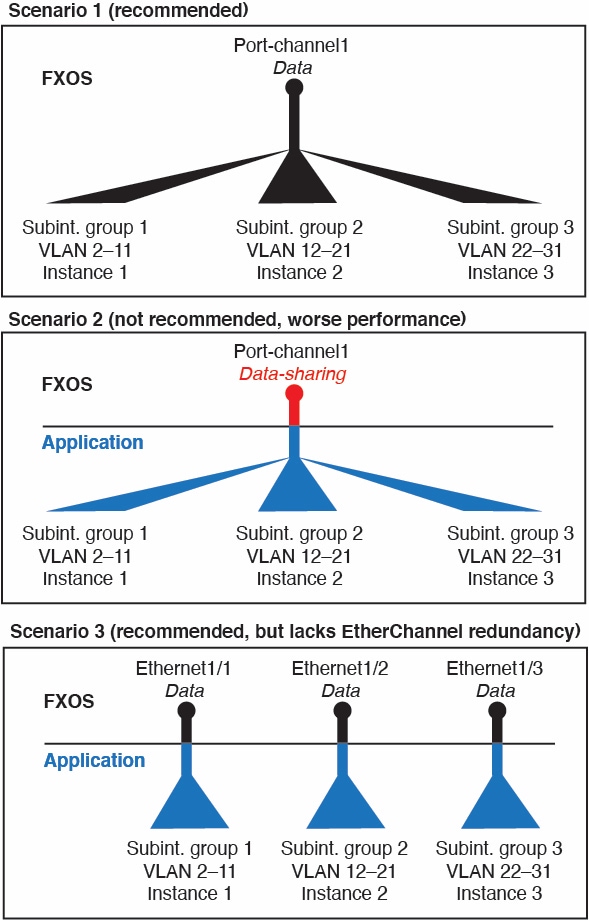
You can also create VLAN subinterfaces in the chassis. The instance-defined subinterfaces are not subject to the chassis limit. Choosing in which location to create subinterfaces depends on your network deployment and personal preference. For example, to share a subinterface, you must create the subinterface on the chassis. Another scenario that favors chassis subinterfaces comprises allocating separate subinterface groups on a single interface to multiple instances. For example, you want to use Port-channel1 with VLAN 2–11 on instance A, VLAN 12–21 on instance B, and VLAN 22–31 on instance C. If you create these subinterfaces in the instance, then you would have to share the parent interface in the chassis, which may not be desirable. See the following illustration that shows the three ways you can accomplish this scenario:
Independent Interface States in the Chassis and in the Instance
You can administratively enable and disable interfaces in both the chassis and in the instance. For an interface to be operational, the interface must be enabled in both locations. Because the interface state is controlled independently, you may have a mismatch between the chassis and instance.
The default state of an interface within the instance depends on the type of interface. For example, the physical interface or EtherChannel is disabled by default within the instance, but a subinterface is enabled by default.
Shared Interface Scalability
Instances can share data-sharing type interfaces. This capability lets you conserve physical interface usage as well as support flexible networking deployments. When you share an interface, the chassis uses unique MAC addresses to forward traffic to the correct instance. However, shared interfaces can cause the forwarding table to grow large due to the need for a full mesh topology within the chassis (every instance must be able to communicate with every other instance that is sharing the same interface). Therefore, there are limits to how many interfaces you can share.
In addition to the forwarding table, the chassis maintains a VLAN group table for VLAN subinterface forwarding. You can create up to 500 VLAN subinterfaces.
See the following limits for shared interface allocation:
Shared Interface Best Practices
For optimal scalability of the forwarding table, share as few interfaces as possible. Instead, you can create up to 500 VLAN subinterfaces on one or more physical interfaces and then divide the VLANs among the container instances.
When sharing interfaces, follow these practices in the order of most scalable to least scalable:
-
Best—Share subinterfaces under a single parent, and use the same set of subinterfaces with the same group of instances.
For example, create a large EtherChannel to bundle all of your like-kind interfaces together, and then share subinterfaces of that EtherChannel: Port-Channel1.2, 3, and 4 instead of Port-Channel2, Port-Channel3, and Port-Channel4. When you share subinterfaces from a single parent, the VLAN group table provides better scaling of the forwarding table than when sharing physical/EtherChannel interfaces or subinterfaces across parents.
Figure 2. Best: Shared Subinterface Group on One Parent 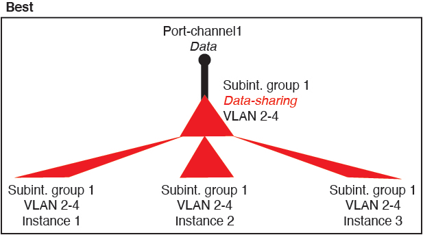
If you do not share the same set of subinterfaces with a group of instances, your configuration can cause more resource usage (more VLAN groups). For example, share Port-Channel1.2, 3, and 4 with instances 1, 2, and 3 (one VLAN group) instead of sharing Port-Channel1.2 and 3 with instances 1 and 2, while sharing Port-Channel1.3 and 4 with instance 3 (two VLAN groups).
Figure 3. Good: Sharing Multiple Subinterface Groups on One Parent 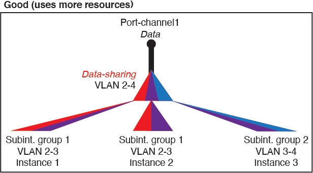
-
Fair—Share subinterfaces across parents.
For example, share Port-Channel1.2, Port-Channel2.3, and Port-Channel3.4 instead of Port-Channel2, Port-Channel4, and Port-Channel4. Although this usage is not as efficient as only sharing subinterfaces on the same parent, it still takes advantage of VLAN groups.
Figure 4. Fair: Shared Subinterfaces on Separate Parents 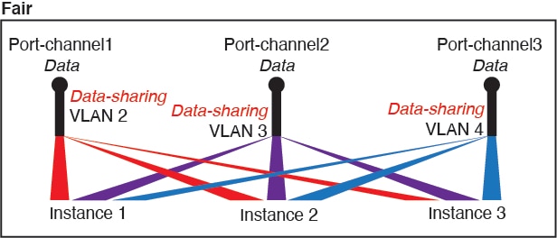
-
Worst—Share individual parent interfaces (physical or EtherChannel).
This method uses the most forwarding table entries.
Figure 5. Worst: Shared Parent Interfaces 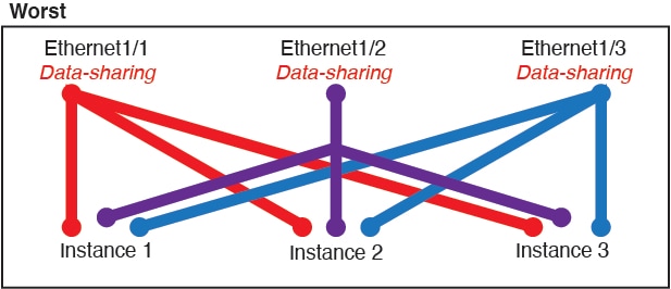
How the Chassis Classifies Packets
Each packet that enters the chassis must be classified, so that the chassis can determine to which instance to send a packet.
-
Unique Interfaces—If only one instance is associated with the ingress interface, the chassis classifies the packet into that instance. For bridge group member interfaces (in transparent mode or routed mode), inline sets, or passive interfaces, this method is used to classify packets at all times.
-
Unique MAC Addresses—The chassis automatically generates unique MAC addresses for all interfaces, including shared interfaces. If multiple instances share an interface, then the classifier uses unique MAC addresses assigned to the interface in each instance. An upstream router cannot route directly to an instance without unique MAC addresses. You can also set the MAC addresses manually when you configure each interface within the application.
Note |
If the destination MAC address is a multicast or broadcast MAC address, the packet is duplicated and delivered to each instance. |
Classification Examples
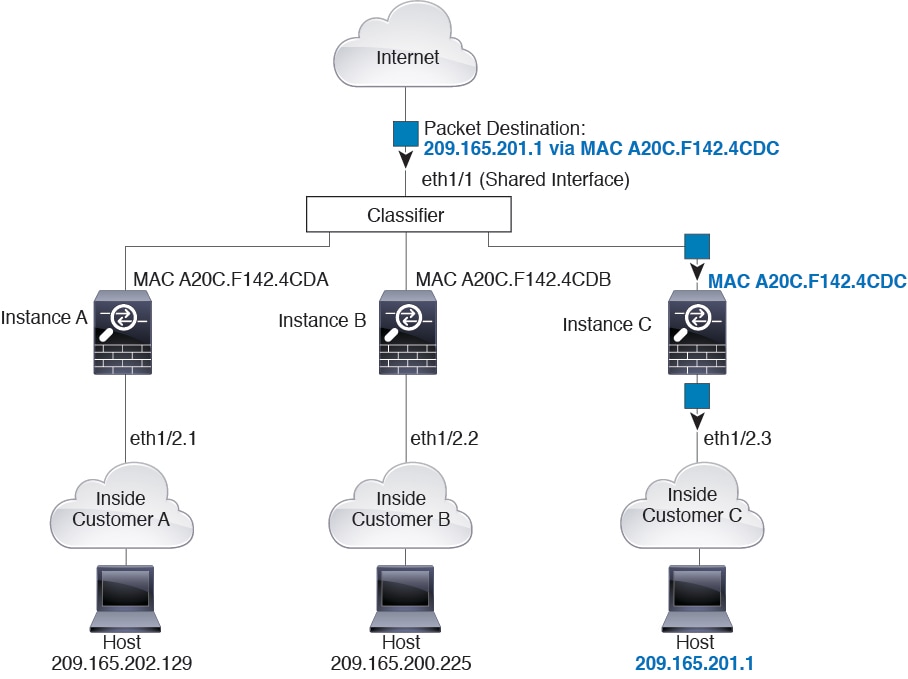
Packet Classification with a Shared Interface Using MAC Addresses
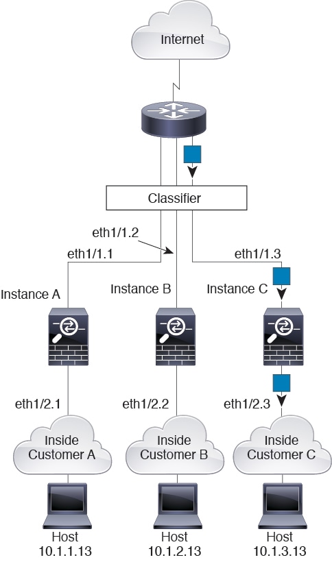
The following figure shows multiple instances sharing an outside interface. The classifier assigns the packet to Instance C because Instance C includes the MAC address to which the router sends the packet.
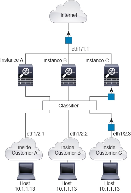
Incoming Traffic from Inside Networks
Note that all new incoming traffic must be classified, even from inside networks. The following figure shows a host on the Instance C inside network accessing the internet. The classifier assigns the packet to Instance C because the ingress interface is Ethernet 1/2.3, which is assigned to Instance C.
Transparent Firewall Instances
For transparent firewalls, you must use unique interfaces. The following figure shows a packet destined to a host on the Instance C inside network from the internet. The classifier assigns the packet to Instance C because the ingress interface is Ethernet 1/2.3, which is assigned to Instance C.
Inline Sets
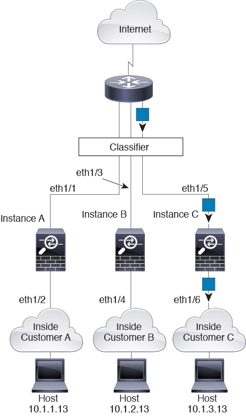
For inline sets, you must use unique interfaces and they must be physical interfaces or EtherChannels. The following figure shows a packet destined to a host on the Instance C inside network from the internet. The classifier assigns the packet to Instance C because the ingress interface is Ethernet 1/5, which is assigned to Instance C.
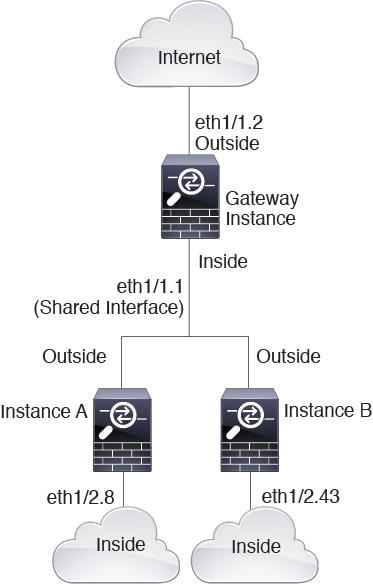
Cascading Instances
Placing an instance directly in front of another instance is called cascading instances; the outside interface of one instance is the same interface as the inside interface of another instance. You might want to cascade instances if you want to simplify the configuration of some instances by configuring shared parameters in the top instance.
The following figure shows a gateway instance with two instances behind the gateway.
Note |
Do not use cascading instances (using a shared interface) with High Availability. After a failover occurs and the standby unit rejoins, MAC addresses can overlap temporarily and cause an outage. You should instead use unique interfaces for the gateway instance and inside instance using an external switch to pass traffic between the instances. |
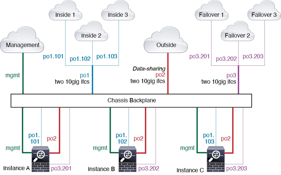
Typical Multi-Instance Deployment
The following example includes three container instances in routed firewall mode. They include the following interfaces:
-
Management—All instances and the chassis use the dedicated Management interface. Within each instance (and the chassis), the interface uses a unique IP address on the same management network.
-
Inside—Each instance uses a subinterface on Port-Channel1 (data type). This EtherChannel includes two 10 Gigibit Ethernet interfaces. Each subinterface is on a separate network.
-
Outside—All instances use the Port-Channel2 interface (data-sharing type). This EtherChannel includes two 10 Gigibit Ethernet interfaces. Within each application, the interface uses a unique IP address on the same outside network.
-
Failover—Each instance uses a subinterface on Port-Channel3 (data type). This EtherChannel includes two 10 Gigibit Ethernet interfaces. Each subinterface is on a separate network.
Automatic MAC Addresses for Instance Interfaces
The chassis automatically generates MAC addresses for instance interfaces, and guarantees that a shared interface in each instance uses a unique MAC address.
If you manually assign a MAC address to a shared interface within the instance, then the manually-assigned MAC address is used. If you later remove the manual MAC address, the autogenerated address is used. In the rare circumstance that the generated MAC address conflicts with another private MAC address in your network, we suggest that you manually set the MAC address for the interface within the instance.
Because autogenerated addresses start with A2, you should not start manual MAC addresses with A2 due to the risk of overlapping addresses.
The chassis generates the MAC address using the following format:
A2xx.yyzz.zzzz
Where xx.yy is a user-defined prefix or a system-defined prefix, and zz.zzzz is an internal counter generated by the chassis. The system-defined prefix matches the lower 2 bytes of the first MAC address in the burned-in MAC address pool that is programmed into the IDPROM. Use connect fxos , then show module to view the MAC address pool. For example, if the range of MAC addresses shown for module 1 is b0aa.772f.f0b0 to b0aa.772f.f0bf, then the system prefix will be f0b0.
The user-defined prefix is an integer that is converted into hexadecimal. For an example of how the user-defined prefix is used, if you set a prefix of 77, then the chassis converts 77 into the hexadecimal value 004D (yyxx). When used in the MAC address, the prefix is reversed (xxyy) to match the chassis native form:
A24D.00zz.zzzz
For a prefix of 1009 (03F1), the MAC address is:
A2F1.03zz.zzzz
Performance Scaling Factor for Multi-Instance Mode
The maximum throughput (connections, VPN sessions) for a platform is calculated for an appliance mode device's use of memory and CPU (and this value is shown in show resource usage ). If you use multiple instances, then you need to calculate the throughput based on the percentage of CPU cores that you assign to the instance. For example, if you use an instance with 50% of the cores, then you should initially calculate 50% of the throughput. Moreover, the throughput available to an instance may be less than that available to an appliance.
For detailed instructions on calculating the throughput for instances, see https://www.cisco.com/c/en/us/products/collateral/security/firewalls/white-paper-c11-744750.html.
Instances and High Availability
You can use High Availability using an instance on 2 separate chassis; for example, if you have 2 chassis, each with 10 instances, you can create 10 High Availability pairs. You can also have standalone instances on the same chassis as High Availability instances. For detailed requirements, see Requirements and Prerequisites for Instances.
Note |
Clustering is not supported. |
Licenses for Instances
All licenses are consumed per chassis and not per instance. See the following details:
-
Essentials licenses are assigned to the chassis as a whole, one per chassis.
-
Feature licenses are assigned to each instance, but you only consume one license per feature per chassis.
Requirements and Prerequisites for Instances
Model Support
-
Secure Firewall 3110
-
Secure Firewall 3120
-
Secure Firewall 3130
-
Secure Firewall 3140
-
Secure Firewall 4215
-
Secure Firewall 4225
-
Secure Firewall 4245
Note |
The Secure Firewall 3105 is not supported. |
Maximum Container Instances and Resources per Model
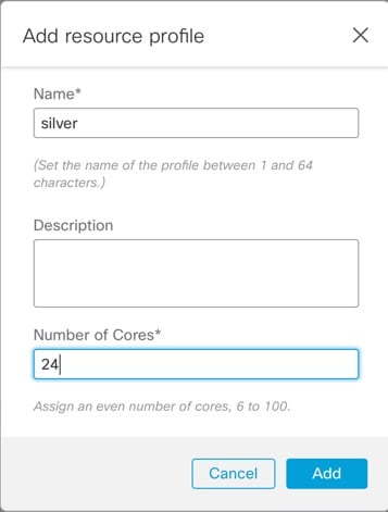
For each container instance, you can specify the number of CPU cores (or more specifically, threads) to assign to the instance. We use the term "core" generically to account for different hardware architecture. RAM is dynamically allocated according to the number of cores, and disk space is set to 40 GB per instance.
|
Model |
Max. Container Instances |
Available CPU Cores (Threads) |
|---|---|---|
|
Secure Firewall 3110 |
3 |
22 |
|
Secure Firewall 3120 |
5 |
30 |
|
Secure Firewall 3130 |
7 |
46 |
|
Secure Firewall 3140 |
10 |
62 |
|
Secure Firewall 4215 |
10 |
62 |
|
Secure Firewall 4225 |
21 |
126 |
|
Secure Firewall 4245 |
34 |
254 |
Software Requirements
-
You can run different versions of Firewall Threat Defense software on each instance as long as they are all compatible with the version of FXOS running on the chassis.
-
You cannot deploy an instance with a patch version of the Firewall Threat Defense software because it is not a complete bundle. You need to first deploy the major or maintenance version, and then patch it after deployment.
High Availability Requirements
-
The two instances in a High Availability configuration must:
-
Be on separate chassis.
-
Be on the same model.
-
Have the same interfaces assigned. All interfaces must be preconfigured in the chassis identically before you enable High Availability.
-
Use the same resource profile attributes. The profile names can be different, but the definitions need to match.
-
Firewall Management Center Requirements
For chassis management and all instances on the chassis, you must use the same Firewall Management Center due to the licensing implementation.
Guidelines and Limitations for Instances
General Guidelines
-
A single Firewall Management Center must manage all instances on a chassis, as well as manage the chassis itself.
-
For instances, the following features are not supported:
-
TLS crypto acceleration
-
Clustering
-
Firewall Management Center UCAPL/CC mode
-
Flow offload to hardware
-
LLDP
-
-
Primary management of the chassis by Security Cloud Control cloud-delivered Firewall Management Center and separate analytics-only management of the chassis by an on-prem Firewall Management Center is not supported. You can however add Security Cloud Control-managed instances to an analytics-only on-prem Firewall Management Center.
Management Interface
-
No support for a data interface for chassis management; only the dedicated Management interface can be used
-
No DHCP addressing for the Management interface
-
The management connection requires TCP port 8305; do not change the value from the default.
VLAN Subinterfaces
-
This document discusses chassis VLAN subinterfaces only. You can separately create subinterfaces within the instance.
-
If you assign a parent interface to an instance, it only passes untagged (non-VLAN) traffic. Do not assign the parent interface unless you intend to pass untagged traffic.
-
Subinterfaces are supported on Data or Data-sharing type interfaces.
-
You can create up to 500 VLAN IDs.
-
You cannot use subinterfaces for an inline set or as a passive interface.
-
If you use a subinterface for the failover link, then all subinterfaces on that parent, and the parent itself, are restricted for use as failover links. You cannot use some subinterfaces as failover links, and some as regular data interfaces.
EtherChannels
-
You can configure up to 48 EtherChannels, limited by the number of physical interfaces.
-
The EtherChannel can have up to 8 active interfaces.
-
All interfaces in the EtherChannel must be the same media type and speed capacity. The media type can be either RJ-45 or SFP; SFPs of different types (copper and fiber) can be mixed. You cannot mix interface capacities (for example 1GB and 10GB interfaces) by setting the speed to be lower on the larger-capacity interface, unless you set the speed to Detect SFP; in this case, you can use different interface capacities, and the lowest common speed is used.
-
The chassis does not support LACPDUs that are VLAN-tagged. If you enable native VLAN tagging on the neighboring switch using the Cisco IOS vlan dot1Q tag native command, then the chassis will drop the tagged LACPDUs. Be sure to disable native VLAN tagging on the neighboring switch.
-
In Cisco IOS software versions earlier than 15.1(1)S2, the chassis did not support connecting an EtherChannel to a switch stack. With default switch settings, if the chassis EtherChannel is connected cross stack, and if the primary switch is powered down, then the EtherChannel connected to the remaining switch will not come up. To improve compatibility, set the stack-mac persistent timer command to a large enough value to account for reload time; for example, 8 minutes or 0 for indefinite. Or, you can upgrade to more a more stable switch software version, such as 15.1(1)S2.
Data-sharing Interfaces
-
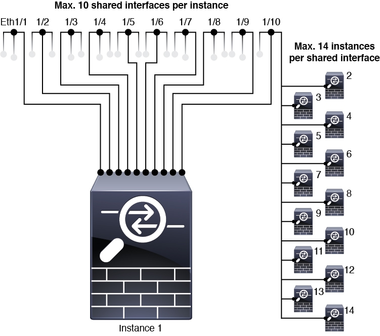
Maximum 14 instances per shared interface. For example, you can allocate Ethernet1/1 to Instance1 through Instance14.
Maximum 10 shared interfaces per instance. For example, you can allocate Ethernet1/1.1 through Ethernet1/1.10 to Instance1.
-
You cannot use a data-sharing interface with a transparent firewall mode instance.
-
You cannot use a data-sharing interface with inline sets or passive interfaces.
-
You cannot use a data-sharing interface for the failover link.
Default MAC Addresses
-
MAC addresses for all interfaces are taken from a MAC address pool. For subinterfaces, if you decide to manually configure MAC addresses, make sure you use unique MAC addresses for all subinterfaces on the same parent interface to ensure proper classification. See Automatic MAC Addresses for Instance Interfaces.
Configure Instances
Before you configure instances, you need to enable multi-instance mode, add the chassis to the Firewall Management Center, and configure chassis interfaces. You can also customize the chassis settings.
Convert a Device to Multi-Instance Mode
Use this procedure to convert a device in the Firewall Management Center to multi-instance mode. The conversion takes approximately 15 minutes. The system reboots and, as part of changing the mode, erases the configuration with the exception of the Management network settings and the admin password. The chassis hostname is set to "firepower-model." The Management IP address is assigned to the chassis for the management connection with the Firewall Management Center. When you add instances, they will use separate IP addresses on the Management interface and maintain their own management connections.
After you convert to multi-instance mode, you can use the Firewall Management Center to configure all chassis settings as well as instances. The Secure Firewall Chassis Manager or configuration at the FXOS CLI is not supported.
Note |
If you would prefer to use the CLI to convert to multi-instance mode before adding the device to the Firewall Management Center, see Enable Multi-Instance Mode at the CLI. |
Before you begin
Add the appliance-mode device to the Firewall Management Center as a standalone device. This device cannot use:
-
A data interface for manager access
-
DHCP for the Management interface
-
Zero-Touch Provisioning
Procedure
|
Step 1 |
On , next to the device you want to convert to multi-instance mode, choose More ( 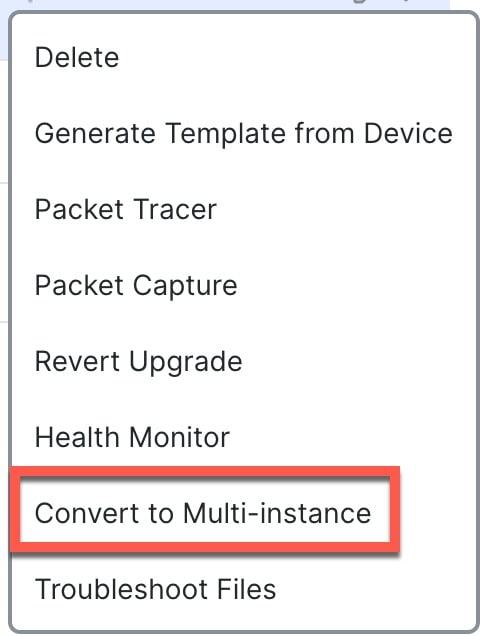
You can alternatively check the check-box next to multiple devices that you want to convert, and choose . 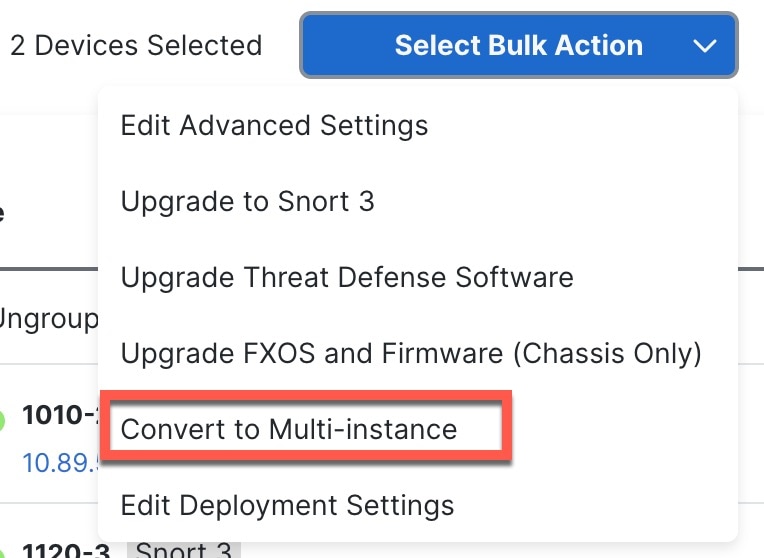
|
||
|
Step 2 |
Confirm that you want to perform the conversion and click Continue. 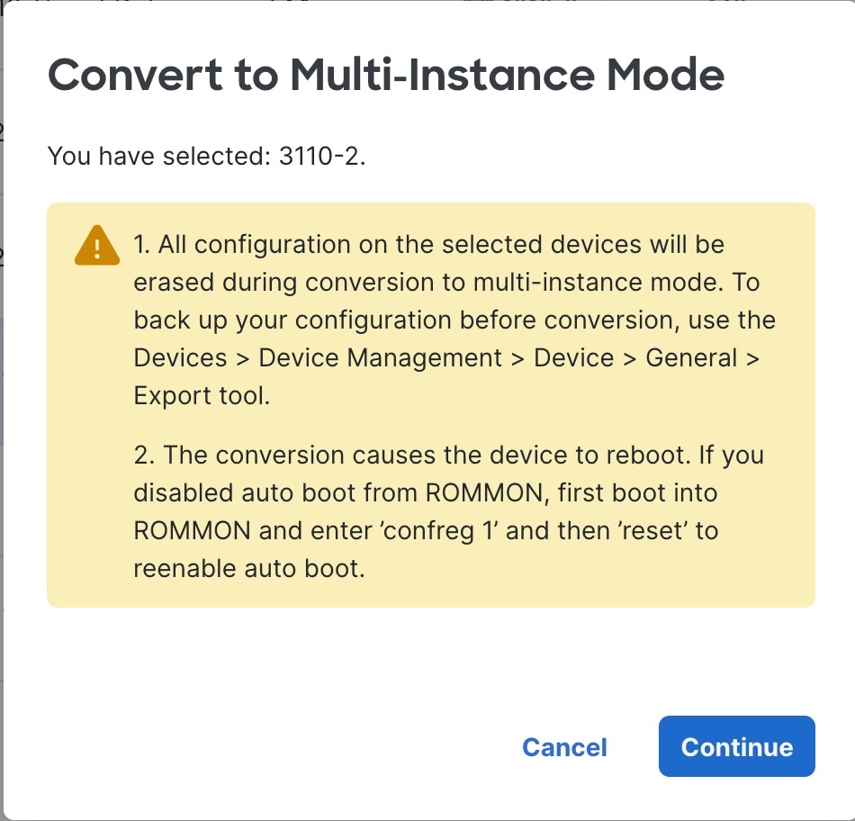
A readiness check is performed. The check might fail if, for example, a deployment is in progress. |
||
|
Step 3 |
Optionally change the name of the chassis, and click Convert to Multi-Instance. By default, the device name is used, but you may want a different naming convention for multi-instance chassis.

Wait for approximately 15 minutes, during which the device is removed from the device list, and then after conversion, it is re-added as a chassis. |
||
|
Step 4 |
To view and configure the chassis, click Manage in the
Chassis column, or click Edit ( The Chassis Manager page opens for the chassis to the Summary page. 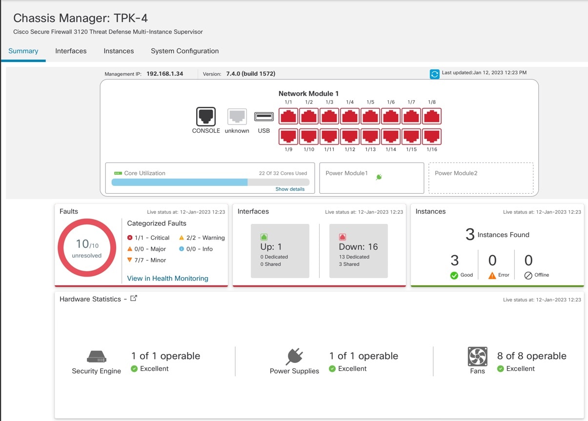
|

 to rerun the readiness check so you can continue.

Configure Chassis Interfaces
At the chassis-level, you configure basic Ethernet settings of physical interfaces, VLAN subinterfaces for instances, and EtherChannel interfaces. By default, physical interfaces are disabled.
Configure a Physical Interface
You can physically enable and disable interfaces, as well as set the interface speed and duplex and other hardware settings. To use an interface, it must be physically enabled for the chassis and logically enabled in the instance. By default, physical interfaces are disabled. For VLAN subinterfaces, the admin state is inherited from the parent interface.
Procedure
|
Step 1 |
From , click Manage in the Chassis column or click Edit ( 
The Chassis Manager page opens for the chassis to the Summary page. |
||
|
Step 2 |
Click Interfaces. 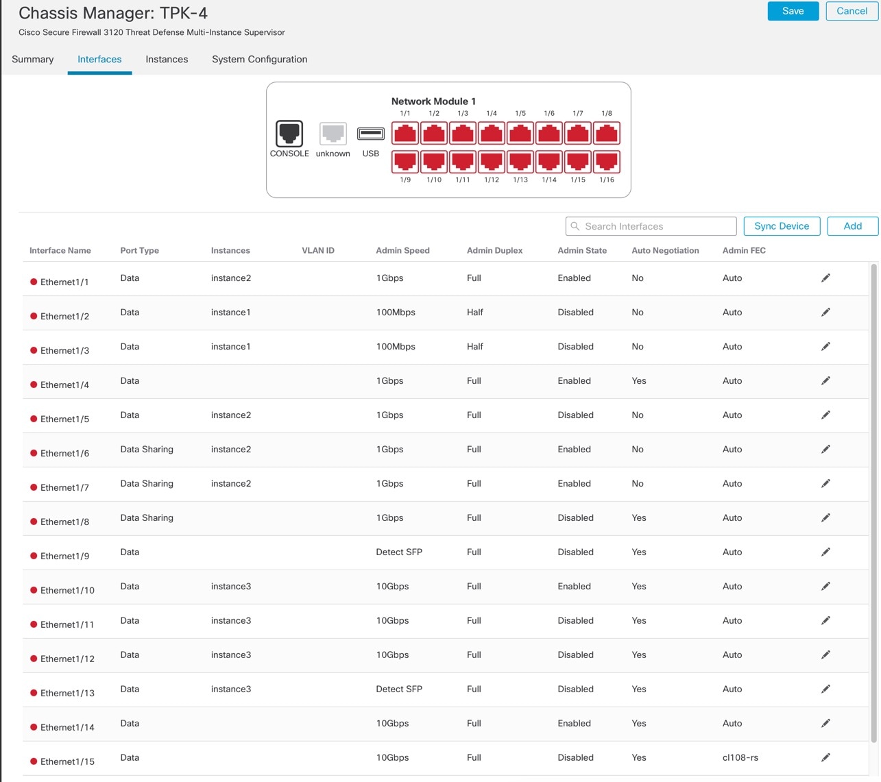
|
||
|
Step 3 |
Click Edit ( 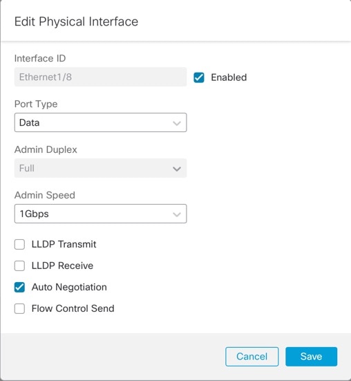
|
||
|
Step 4 |
Enable the interface by checking the Enabled check box. |
||
|
Step 5 |
For the Port Type, choose Data or Data Sharing. 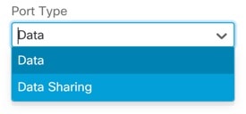
|
||
|
Step 6 |
Set the Admin Duplex. Speeds of 1Gbps and higher only support Full duplex. SFP interfaces only support Full duplex. |
||
|
Step 7 |
Set the Admin Speed. For SFPs, Choose Detect SFP to detect the speed of the installed SFP module and use the appropriate speed. Duplex is always Full, and auto-negotiation is always enabled. This option is useful if you later change the network module to a different model, and want the speed to update automatically. |
||
|
Step 8 |
(Optional) Check Flow Control Send to enable pause (XOFF) frames for flow control. Flow control enables connected Ethernet ports to control traffic rates during congestion by allowing congested nodes to pause link operation at the other end. If the threat defense port experiences congestion (exhaustion of queuing resources on the internal switch) and cannot receive any more traffic, it notifies the other port by sending a pause frame to stop sending until the condition clears. Upon receipt of a pause frame, the sending device stops sending any data packets, which prevents any loss of data packets during the congestion period.
The internal switch has a global pool of 8000 buffers of 250 bytes each, and the switch allocates buffers dynamically to each port. A pause frame is sent out every interface with flow control enabled when the buffer usage exceeds the global high-water mark (2 MB (8000 buffers)); and a pause frame is sent out of a particular interface when its buffer exceeds the port high-water mark (.3125 MB (1250 buffers)). After a pause is sent, an XON frame can be sent when the buffer usage is reduced below the low-water mark (1.25 MB globally (5000 buffers); .25 MB per port (1000 buffers)). The link partner can resume traffic after receiving an XON frame. Only flow control frames defined in 802.3x are supported. Priority-based flow control is not supported. |
||
|
Step 9 |
(Optional) Check Auto Negotiation to set the interface to negotiate the speed, link status, and flow control. You cannot edit this setting for speeds lower than 1Gbps. For SFP interfaces, you can only disable auto-negotiation when the speed is set to 1Gbps. |
||
|
Step 10 |
Click Save and then Save in the top right of the Interfaces page. You can now Deploy the policy to the chassis. The changes are not active until you deploy them. |
Configure an EtherChannel
An EtherChannel (also known as a port channel) can include up to 8 member interfaces of the same media type and capacity, and must be set to the same speed and duplex. The media type can be either RJ-45 or SFP; SFPs of different types (copper and fiber) can be mixed. You cannot mix interface capacities (for example 1GB and 10GB interfaces) by setting the speed to be lower on the larger-capacity interface, unless you set the speed to Detect SFP; in this case, you can use different interface capacities, and the lowest common speed is used.
The Link Aggregation Control Protocol (LACP) aggregates interfaces by exchanging the Link Aggregation Control Protocol Data Units (LACPDUs) between two network devices. LACP coordinates the automatic addition and deletion of links to the EtherChannel without user intervention. It also handles misconfigurations and checks that both ends of member interfaces are connected to the correct channel group. “On” mode cannot use standby interfaces in the channel group when an interface goes down, and the connectivity and configurations are not checked.
When the chassis creates an EtherChannel, the EtherChannel stays in a Suspended state for Active LACP mode or a Down state for On LACP mode until you assign it to a logical device, even if the physical link is up. The EtherChannel will be brought out of this Suspended state when it is added to an instance.
Before you begin
Enable physical interfaces and set hardware parameters. See Configure a Physical Interface.
Procedure
|
Step 1 |
From , click Manage in the Chassis column or click Edit (
The Chassis Manager page opens for the chassis to the Summary page. |
||
|
Step 2 |
Click Interfaces.
|
||
|
Step 3 |
Click . 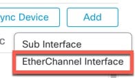
|
||
|
Step 4 |
Set the following Interfaces parameters. 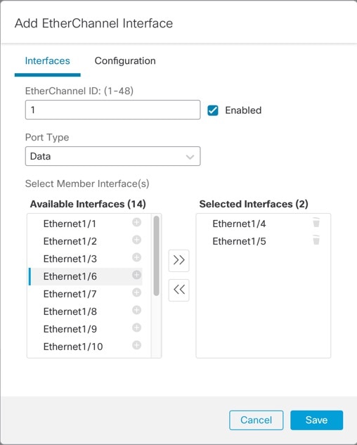
|
||
|
Step 5 |
(Optional) Set the following Configuration parameters. Many of these settings (excluding the LACP settings) set the requirements for interfaces to be included in the EtherChannel; they do not override the settings of member interfaces. So if you check LLDP Transmit, for example, you should only add interfaces that have that setting. If you set the Admin Speed to 1Gbps, then only 1Gbps interfaces can be included. 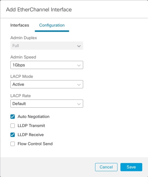
|
||
|
Step 6 |
Click Save and then Save in the top right of the Interfaces page. You can now Deploy the policy to the chassis. The changes are not active until you deploy them. |

Configure a Subinterface
You can add up to 500 subinterfaces to your chassis.
VLAN IDs per interface must be unique, and within an instance, VLAN IDs must be unique across all assigned interfaces. You can reuse VLAN IDs on separate interfaces as long as they are assigned to different instances. However, each subinterface still counts towards the limit even though it uses the same ID.
This section discusses FXOS VLAN subinterfaces only. You can separately create subinterfaces within the instance. See Chassis Interfaces vs. Instance Interfaces.
Procedure
|
Step 1 |
From , click Manage in the Chassis column or click Edit (
The Chassis Manager page opens for the chassis to the Summary page. |
|
Step 2 |
Click Interfaces.
|
|
Step 3 |
Click . 
|
|
Step 4 |
Set the following parameters. 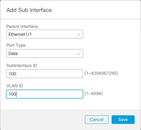
|
|
Step 5 |
Click Save and then Save in the top right of the Interfaces page. You can now Deploy the policy to the chassis. The changes are not active until you deploy them. |
Add an Instance
You can add one or more instances to a chassis in multi-instance mode. The number of supported instances depends on your model; see Requirements and Prerequisites for Instances.
Before you begin
Procedure
|
Step 1 |
From , click Manage in the Chassis column or click Edit (
The Chassis Manager page opens for the chassis to the Summary page. |
||
|
Step 2 |
Click Instances, and click Add Instance. 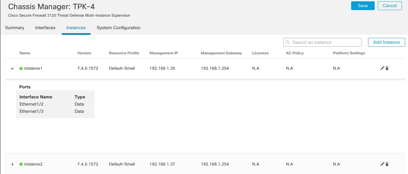
|
||
|
Step 3 |
On Agreement, check I understand and accept the agreement, then click Next. 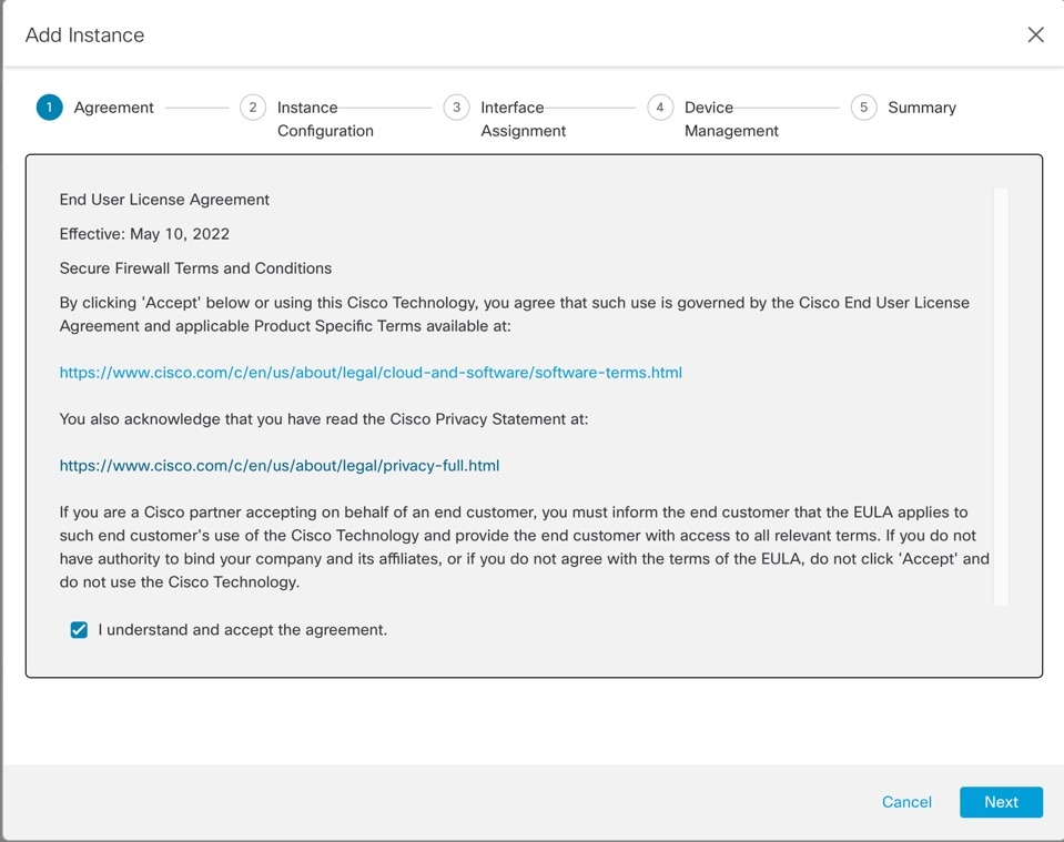
|
||
|
Step 4 |
On Instance Configuration, set the instance parameters, then click Next. 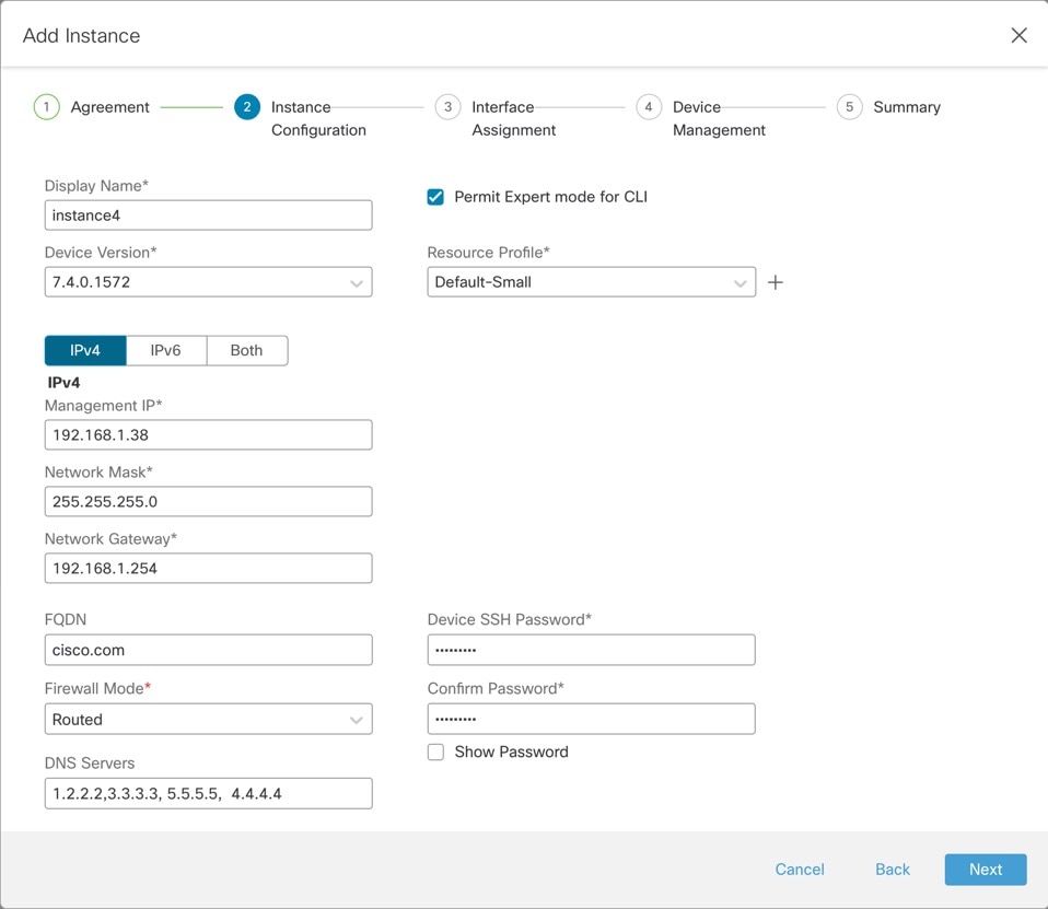
|
||
|
Step 5 |
On Interface Assignment, assign the chassis interfaces to the instance, then click Next. 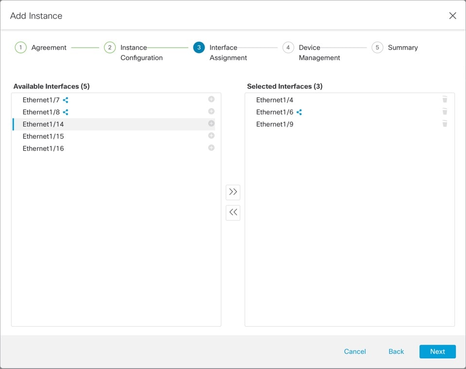
Shared interfaces show the sharing icon ( |
||
|
Step 6 |
On Device Management, set the device-specific settings, then click Next. 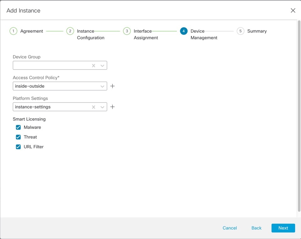
|
||
|
Step 7 |
On Summary, confirm your settings, then click Save. 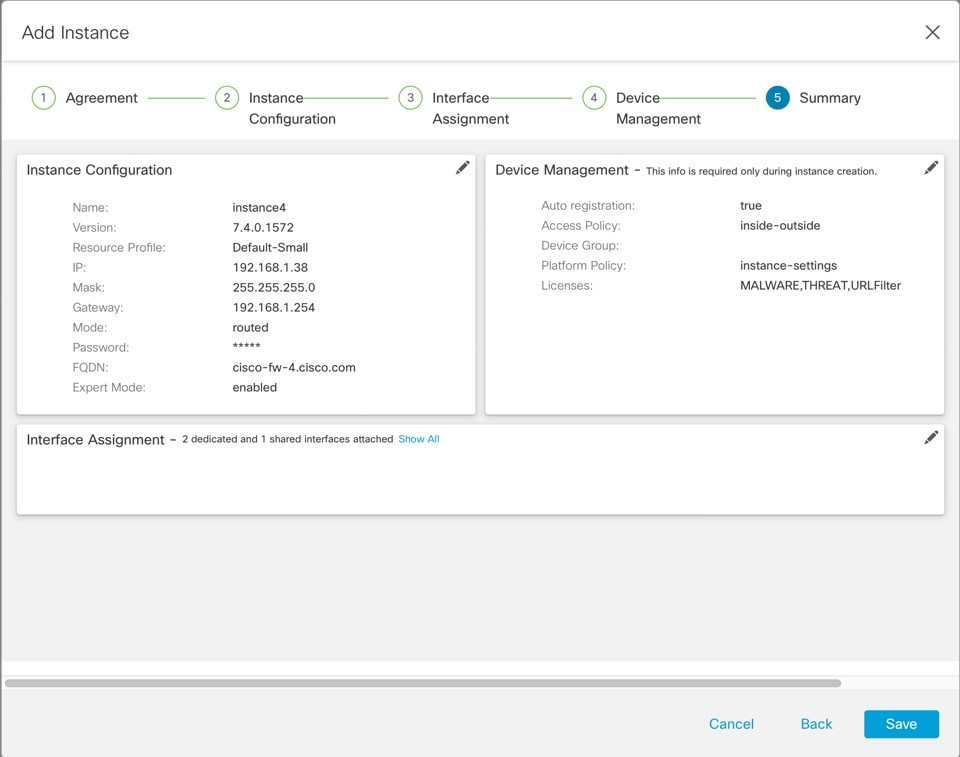
You can edit any settings on this screen before saving the instance. After you save, the instance is added to the Instances screen. |
||
|
Step 8 |
On the Instances screen, click Save. |
||
|
Step 9 |
Deploy the chassis configuration. After deployment, the instance will be added as a device on the Device Management page. |

 ).
).
Customize the System Configuration
You can configure chassis-level settings such as SNMP. You can also import or export the chassis FXOS configuration.
Configure SNMP
You can access chassis-level MIBs through the data interface of one of the instances, which you specify in the chassis system configuration. You can only use this instance for chassis SNMP information. You cannot access SNMP through the chassis Management interface.
Before you begin
-
Configure SNMP for one of the instances.
Procedure
|
Step 1 |
From , click Manage in the Chassis column or click Edit (
The Chassis Manager page opens for the chassis to the Summary page. |
|
Step 2 |
Click System Configuration. |
|
Step 3 |
Click SNMP, and choose the instance from the drop-down list. 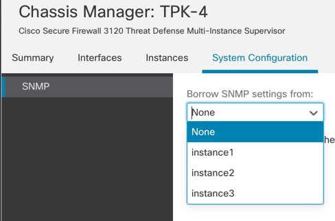
SNMP on the chassis will be accessible from the selected instance. |
|
Step 4 |
Click Save. |
|
Step 5 |
Deploy the chassis configuration. |
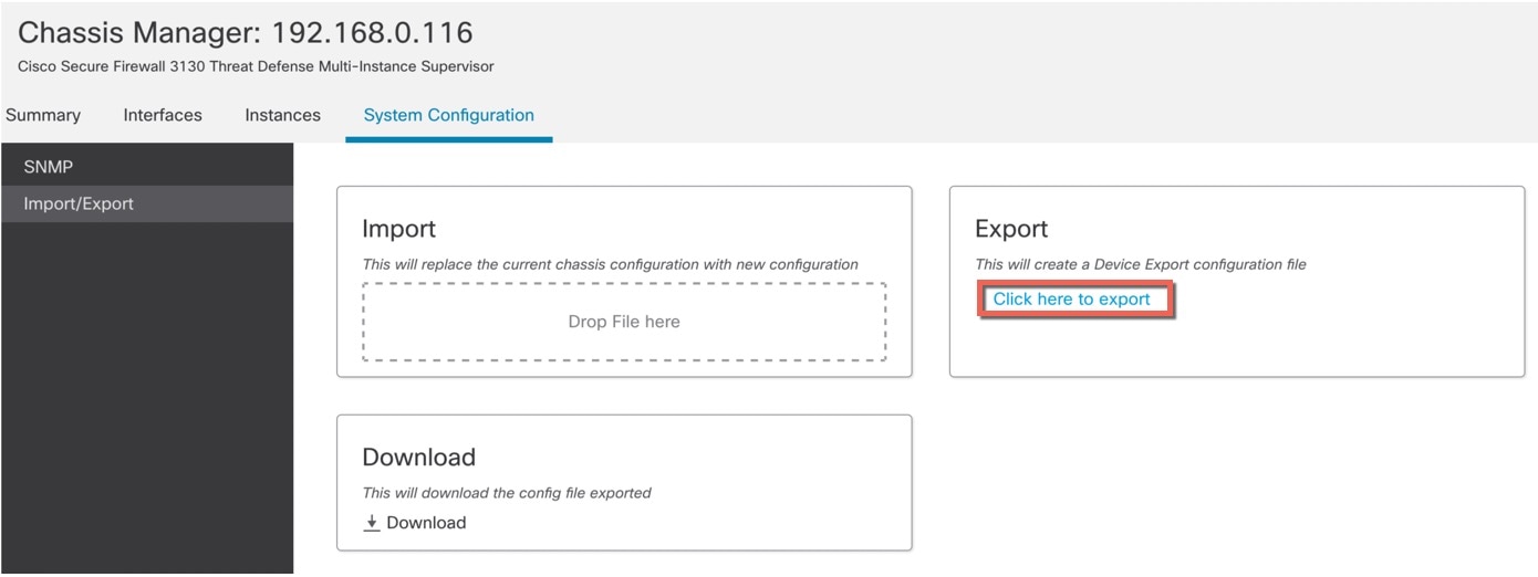
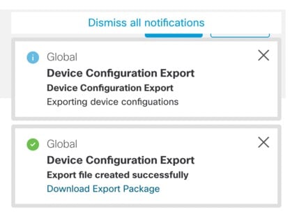
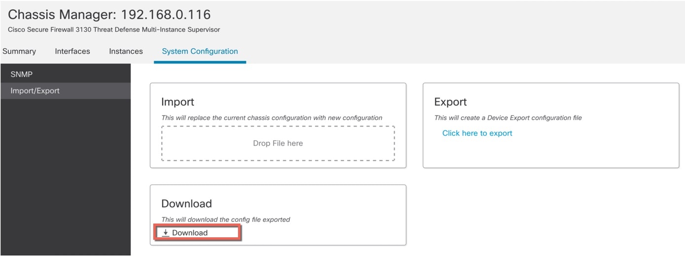
Import or Export the Chassis Configuration
You can use the configuration export feature to export an XML file containing chassis configuration settings to your local computer. You can later import that configuration file to quickly apply the configuration settings to your chassis to return to a known good configuration or to recover from a system failure. You can also import the chassis configuration to a new chassis, for example for an RMA, as long as the prerequisites are met.
When exporting, only chassis configurations are exported; instance configuration settings are not exported. Instances need to be backed up separately using the device backup/restore feature.
When importing, all existing configurations on the chassis will be replaced by the configuration in the import file.
Before you begin
For the chassis where you want to import a configuration, the following characteristics must match:
-
Same chassis software version
-
Same Firewall Threat Defense instance images
-
Same network modules
Procedure
|
Step 1 |
From , click Manage in the Chassis column or click Edit (
The Chassis Manager page opens for the chassis to the Summary page. |
|
Step 2 |
Click System Configuration. |
|
Step 3 |
Click Import/Export. |
|
Step 4 |
To export the configuration, follow these steps.
|
|
Step 5 |
To import a configuration, drag the .sfo file on the area. 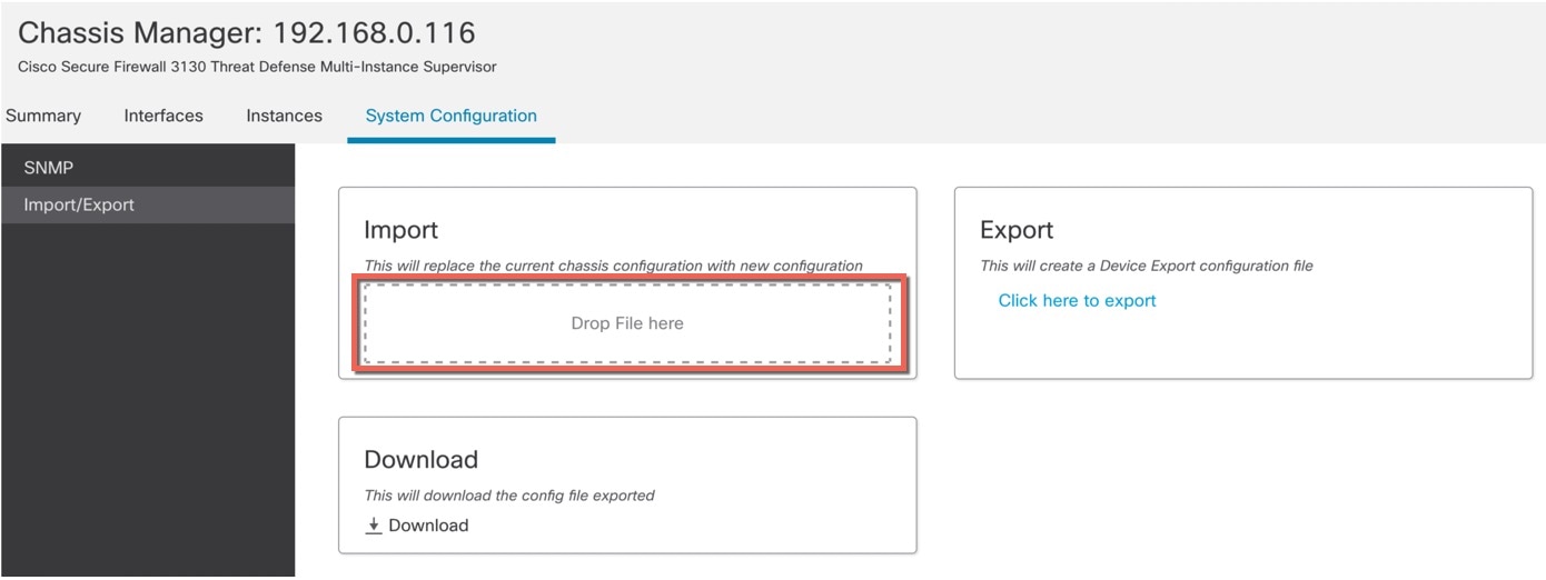
|
Configure Chassis Platform Settings
Chassis platform settings configure a range of features for managing the chassis. You can share the policy among multiple chassis. If you want different settings per chassis, you must create multiple policies.
Create a Chassis Platform Settings Policy
Use the Platform Settings page () to manage platform settings policies. This page indicates the type of device for each policy. The Status column shows the device targets for the policy.
Procedure
|
Step 1 |
Choose . |
||
|
Step 2 |
For an existing policy, you can Copy (
|
||
|
Step 3 |
To create a new policy, click New Policy. |
||
|
Step 4 |
To change the target chassis for a policy, click Edit (
|


Configure DNS
You need to specify a DNS server if the chassis requires resolution of hostnames to IP addresses. These chassis DNS settings are separate from the DNS settings per instance, which are configured in the device platform settings.
When you configure multiple DNS servers, the chassis uses servers in a random order. You can configure up to four servers across four DNS server groups. For example, you can configure a single server group with four servers, or you can configure four server groups with one server each.
Procedure
|
Step 1 |
Choose and create or edit the chassis policy. |
|
Step 2 |
Choose DNS. 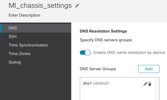
|
|
Step 3 |
Enable the Enable DNS name resolution by device slider. |
|
Step 4 |
Click Add to add a DNS server group. 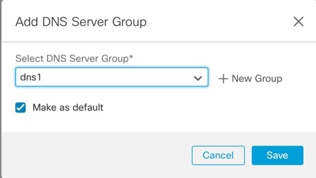
|
|
Step 5 |
Either select an existing DNS server group, or click ( If you add a new group, you see the following dialog box. Provide a name and up to four DNS server IP addresses as comma-separated values, and click Add. 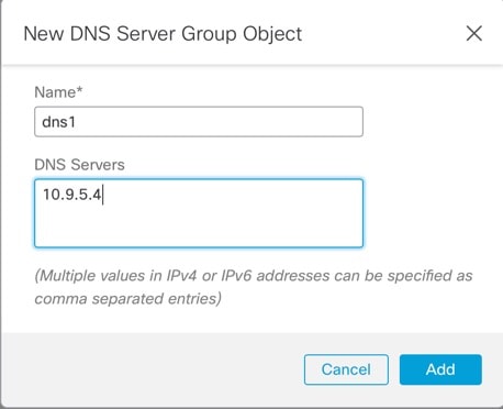
|
|
Step 6 |
Click Save to add the DNS server to the list. |
|
Step 7 |
Repeat these steps to add additional server groups. Make sure you only identify a maximum of four DNS servers in all groups combined. |
|
Step 8 |
Click Save to save all policy changes. |
Configure SSH and SSH Access List
To allow SSH sessions from the admin user to the chassis on the Management interface, enable the SSH server and configure the allowed networks.
Procedure
|
Step 1 |
Choose and create or edit the chassis policy. |
|
Step 2 |
Choose SSH. |
|
Step 3 |
To enable SSH access to the chassis, enable the Enable SSH Server slider. 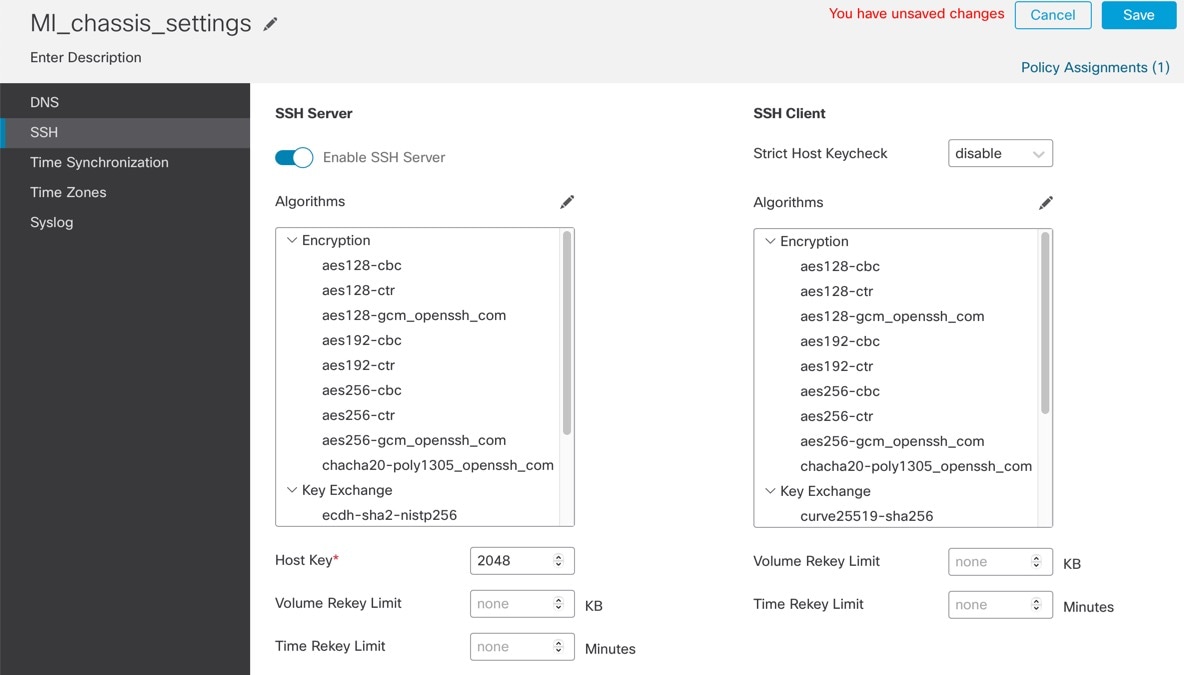
|
|
Step 4 |
To set the allowed Algorithms, click Edit ( 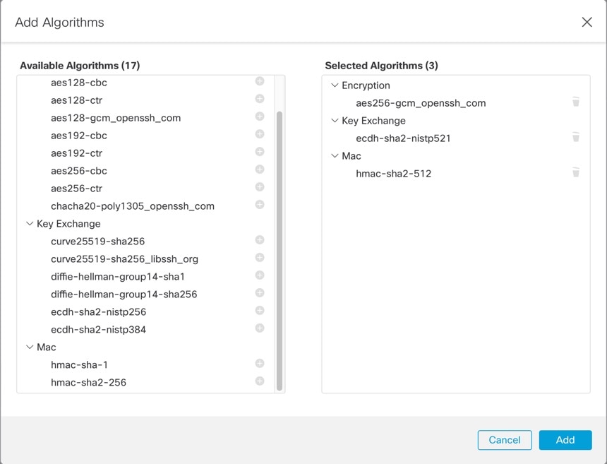
|
|
Step 5 |
For Host Key, enter the modulus size for the RSA key pairs. The modulus value (in bits) is in multiples of 8 from 1024 to 2048. The larger the key modulus size you specify, the longer it takes to generate an RSA key pair. We recommend a value of 2048. |
|
Step 6 |
For the server Volume Rekey Limit, set the amount of traffic in KB allowed over the connection before FXOS disconnects from the session. |
|
Step 7 |
For the server Time Rekey Limit, set the minutes for how long an SSH session can be idle before FXOS disconnects the session. |
|
Step 8 |
For the SSH Client, configure the following settings.
|
|
Step 9 |
Choose SSH Access List. You need to allow access to IP addresses or networks before you can use SSH. You can add up to 25 access lists. 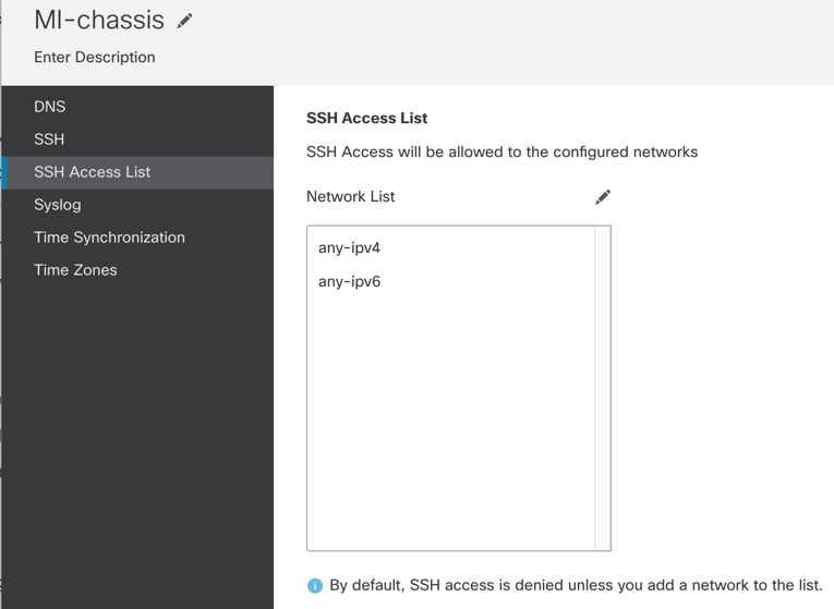
|
|
Step 10 |
Click Edit ( 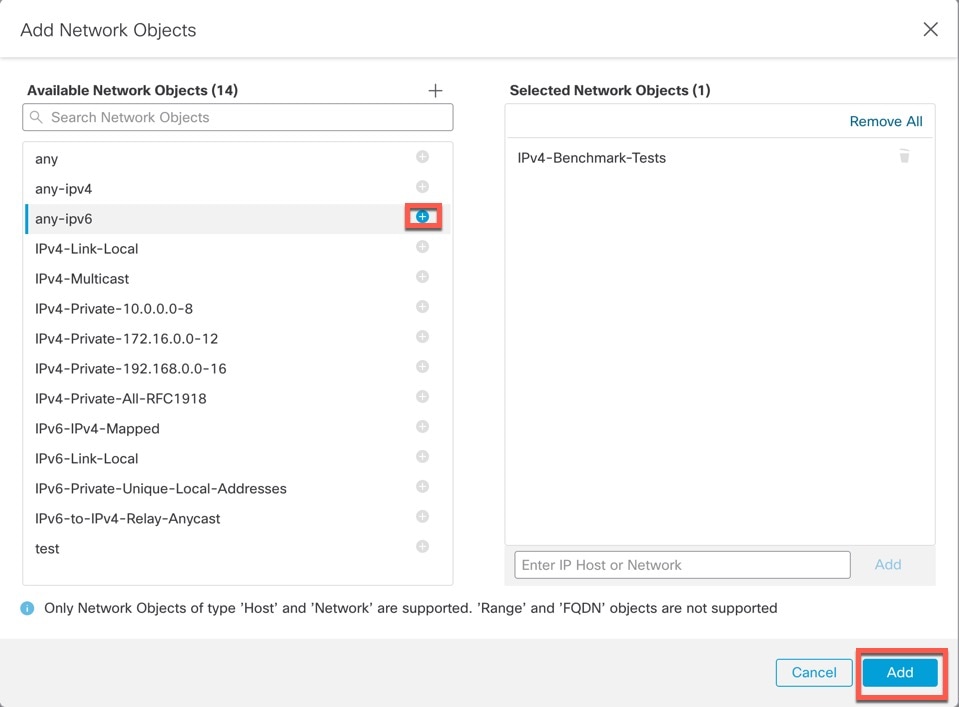
|
|
Step 11 |
Click Save to save all policy changes. |
Configure Syslog
You can enable syslogs from the chassis. These syslogs come from the chassis' FXOS operating system.
Procedure
|
Step 1 |
Choose and create or edit the chassis policy. |
||||||||||||||
|
Step 2 |
Choose Syslog. |
||||||||||||||
|
Step 3 |
Click the Local Destinations tab, and complete the following fields. 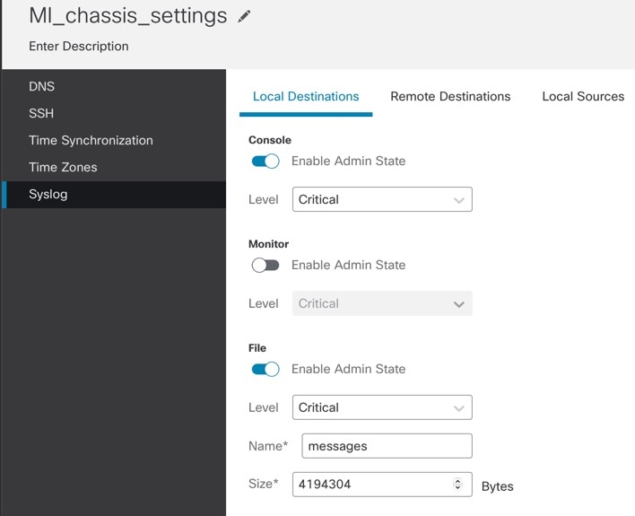
|
||||||||||||||
|
Step 4 |
On the Remote Destinations tab, complete the following fields for up to three external logs that can store messages generated by the chassis: 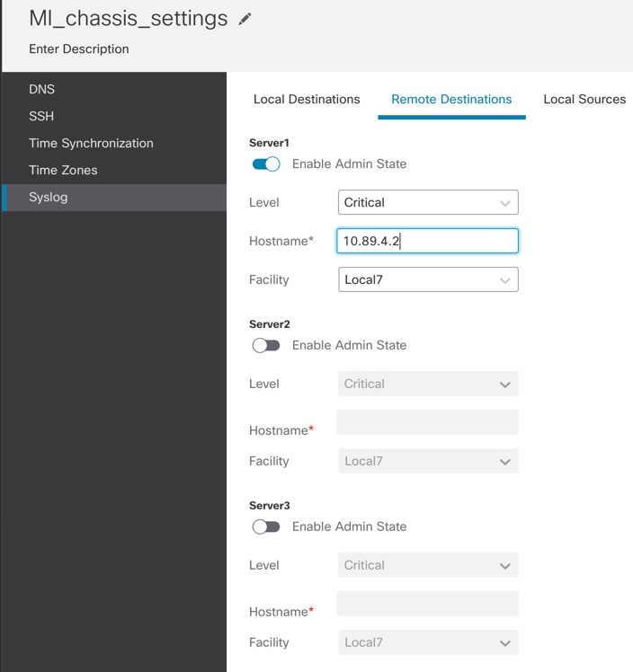
By sending syslog messages to a remote destination, you can archive messages according to the available disk space on the external syslog server, and manipulate logging data after it is saved. For example, you could specify actions to be executed when certain types of syslog messages are logged, extract data from the log and save the records to another file for reporting, or track statistics using a site-specific script.
|
||||||||||||||
|
Step 5 |
Click the Local Sources tab, and complete the following fields. 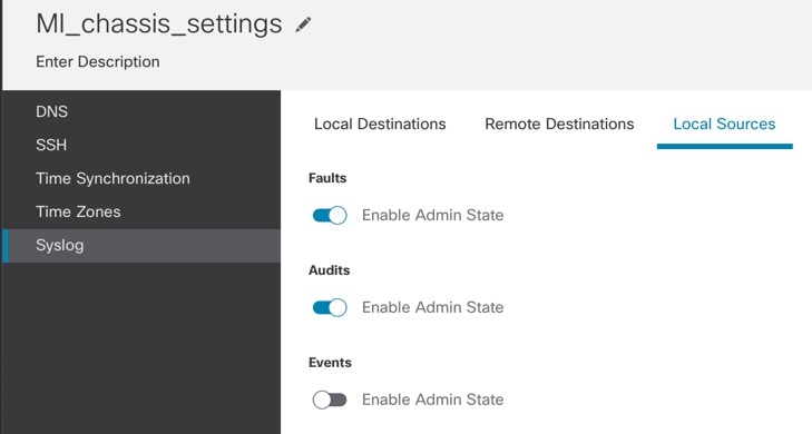
|
||||||||||||||
|
Step 6 |
Click Save to save all policy changes. |
||||||||||||||
Configure Time Synchronization
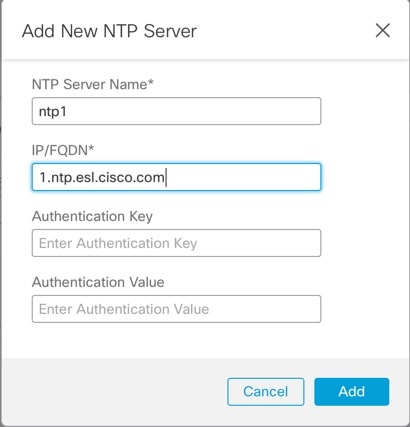
NTP is used to implement a hierarchical system of servers that provide a precisely synchronized time among network systems. This kind of accuracy is required for time-sensitive operations, such as validating CRLs, which include a precise time stamp. You can configure up to four NTP servers.
Note |
|
Before you begin
If you use a hostname for the NTP server, you must configure a DNS server. See Configure DNS.
Procedure
|
Step 1 |
Choose and create or edit the chassis policy. |
|
Step 2 |
Choose Time Synchronization. 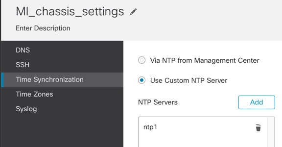
|
|
Step 3 |
If you want to obtain the time from the Firewall Management Center, click Via NTP from Management Center. This option ensures both the chassis and the Firewall Management Center have the same time. |
|
Step 4 |
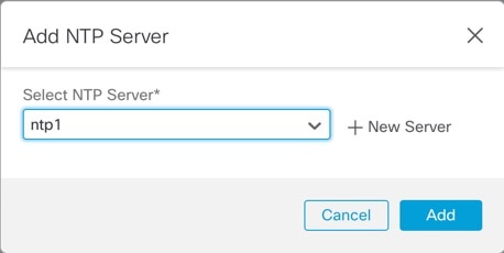
To use an external NTP server, click Use Custom NTP Server.
|
|
Step 5 |
Click Save to save all policy changes. |
Configure Time Zones
Set the time zone for the chassis.
Procedure
|
Step 1 |
Choose and create or edit the chassis policy. |
|
Step 2 |
Choose Time Zones. 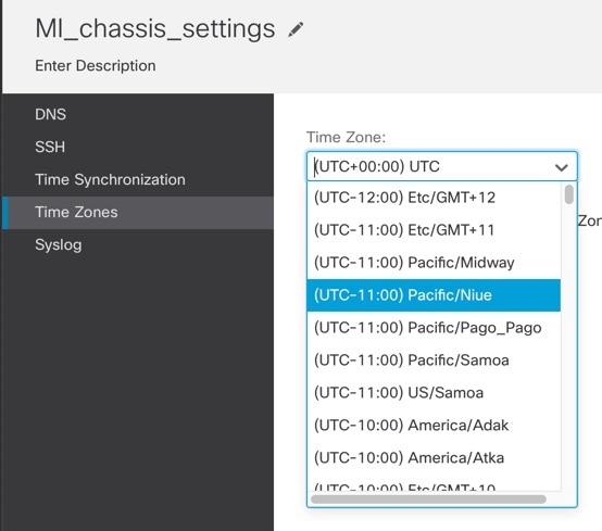
|
|
Step 3 |
Choose your Time Zone from the drop-down menu. |
|
Step 4 |
Click Save to save all policy changes. |
Manage Multi-Instance Mode
This section describes less common tasks, including changing settings at the FXOS CLI or changing interfaces assigned to the chassis.
 Warning |
If an instance is hard deleted from its chassis without first being unregistered, a stale entry will remain visible in the FMC GUI. This entry does not reflect the actual status, deployment type or mode of the deleted instance. To avoid this, always unregister the instance from the Device Management tab before deleting it from it's chassis in the FMC. |
Enable Multi-Instance Mode at the CLI
If you want to pre-configure your devices for multi-instance mode before you add them to the Firewall Management Center, you can perform this procedure. To use the Firewall Management Center to convert to multi-instance mode, see Convert a Device to Multi-Instance Mode.
You need to connect to the Firewall Threat Defense CLI at the console port to enable multi-instance mode. After you configure the mode, you can add it to the Firewall Management Center.
Note |
Although you can connect to SSH on the management port, we recommend using the console port to avoid multiple disconnections. This procedure covers the console port. |
Procedure
|
Step 1 |
Connect to the chassis console port. The console port connects to the FXOS CLI. |
||
|
Step 2 |
Log in with the username admin and the password Admin123. The first time you log in to FXOS, you are prompted to change the password.
Example: |
||
|
Step 3 |
Check your current mode, Native or Container. If the mode is Native, you can continue with this procedure to convert to multi-instance (Container) mode. show system detail Example: |
||
|
Step 4 |
Connect to the Firewall Threat Defense CLI. connect ftd Example: |
||
|
Step 5 |
The first time you log in to the Firewall Threat Defense, you are prompted to accept the General Terms. You are then presented with the CLI setup script. The setup script lets you set the Management interface IP address and other settings. However, when you convert to multi-instance mode, the only settings that are retained are the following.
You will reset the Management IP address and gateway as part of the multi-instance mode command. After you convert to multi-instance mode, you can change Management settings at the FXOS CLI. See Change Chassis Management Settings at the FXOS CLI. |
||
|
Step 6 |
Enable multi-instance mode, set the chassis management interface settings, and identify the Firewall Management Center. You can use IPv4 and/or IPv6 static addressing; DHCP is not supported. After you enter the command, you will be prompted to erase the configuration and reboot. Enter ERASE (all caps). The system reboots and, as part of changing the mode, erases the configuration with the exception of the Management network settings you set in the command and the admin password. The chassis hostname is set to "firepower-model." IPv4: configure multi-instance network ipv4 ip_address network_mask gateway_ip_address manager manager_name {hostname | ipv4_address | DONTRESOLVE} registration_key nat_id IPv6: configure multi-instance network ipv6 ipv6_address prefix_length gateway_ip_address manager manager_name {hostname | ipv6_address | DONTRESOLVE} registration_key nat_id See the following manager components:
To change the mode back to appliance mode, you must use the FXOS CLI and enter scope system and then set deploymode native . See Change Chassis Management Settings at the FXOS CLI. Example: |
||
|
Step 7 |
Add the chassis to the Firewall Management Center. |
Change Interfaces Assigned to an Instance
You can allocate or unallocate an interface on the instance. Adding a new interface, or deleting an unused interface, has minimal impact on the instance configuration. You can also edit the membership of an allocated EtherChannel without affecting the instance. However, deleting an interface that is used in your security policy will impact the configuration.
Interfaces can be referenced directly in many places in the instance configuration, including access rules, NAT, SSL, identity rules, VPN, DHCP server, and so on. Deleting an interface will delete any configuration associated with that interface.
Policies that refer to security zones are not affected.
Note |
For high availability, you need to make the same interface changes for the other unit. Otherwise, high availability might not operate correctly. |
Before you begin
-
Configure your interfaces according to Configure Instances.
-
If you want to add an already-allocated interface to an EtherChannel, you need to unallocate the interface from the instance first, then add the interface to the EtherChannel. For a new EtherChannel, you can then allocate the EtherChannel to the instance.
Procedure
|
Step 1 |
From , click Manage in the Chassis column or click Edit (
The Chassis Manager page opens for the chassis to the Summary page. |
|
Step 2 |
Click Instances, and click Edit (
|
|
Step 3 |
Click Next until you get to the Interface Assignment screen. 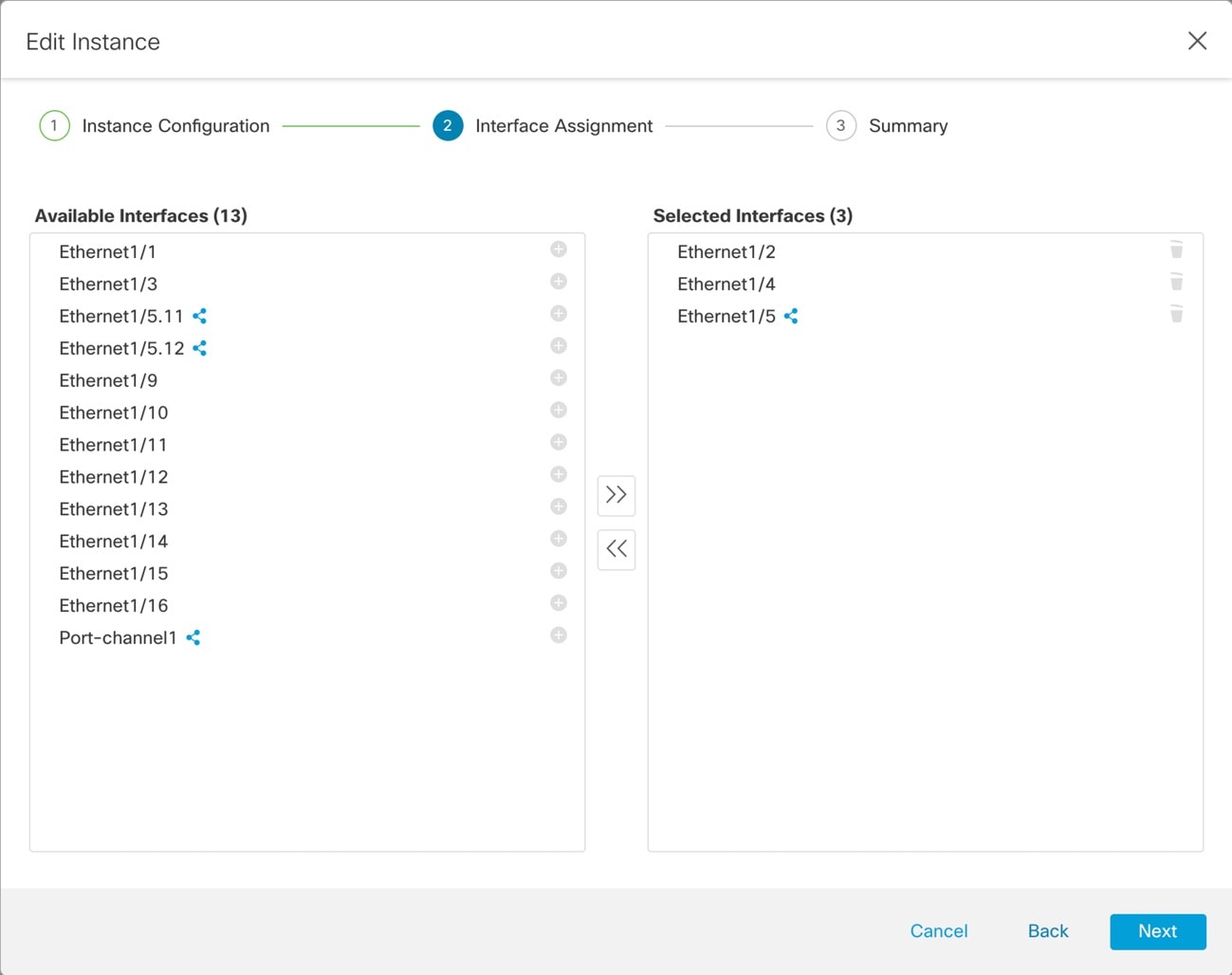
Shared interfaces show the sharing icon ( |
|
Step 4 |
Make your interface changes, and then click Next. |
|
Step 5 |
Click Save on the Summary screen. |
|
Step 6 |
For high availability, you need to make the same interface changes for the other unit. Otherwise, high availability might not operate correctly. |
Change Chassis Management Settings at the FXOS CLI
If you want to change the chassis management interface IP address and gateway, change the Firewall Management Center to a new manager, change the admin password, or disable multi-instance mode, you can do so from the FXOS CLI.
Procedure
|
Step 1 |
Connect to the chassis console port. The console port connects to the FXOS CLI.
|
||
|
Step 2 |
Log in with the username admin and the password you set during initial setup. |
||
|
Step 3 |
Change the Management IP address. You can use a static IPv4 and/or IPv6 address. IPv4: scope fabric-interconnect set out-of-band static ip ip_address netmask network_mask gw gateway_ip_address IPv6: scope fabric-interconnect scope ipv6-config set out-of-band static ipv6 ipv6_address ipv6-prefix prefix_length ipv6-gw gateway_address Example:IPv4: IPv6: |
||
|
Step 4 |
Change the Firewall Management Center. You should first unregister the chassis from the current Firewall Management Center. enter device-manager manager_name [hostname {hostname | ipv4_address | ipv6_address}] [nat-id nat_id] You are prompted for the registration key. You can enter this command from any scope.
Example: |
||
|
Step 5 |
Change the admin password. scope security set password Enter a password: password Confirm the password: password Example: |
||
|
Step 6 |
Disable multi-instance mode and set the system back to appliance mode. scope system set deploymode native You are prompted to reboot. Example:To change the mode back to multi-instance mode, enter set deploymode container . You can check the current mode using the show system detail command. |
Monitoring Multi-Instance Mode
This section helps you troubleshoot and diagnose your multi-instance mode chassis and instances.
Monitoring Multi-Instance Setup
show system detail
This FXOS command shows the current mode, Native or Container. If the mode is Native (also known as appliance mode), you can convert to multi-instance (Container) mode. Note that the prompt/name in multi-instance mode is generic "firepower-<model>" while the prompt in appliance mode is the hostname you set for the Firewall Threat Defense (by default "firepower")
firepower # show system detail

Systems:
    Name: firepower
    Mode: Stand Alone
    System IP Address: 172.16.0.50
    System IPv6 Address: ::
    System Owner:
    System Site:
    Deploy Mode: Native
    Description for System:
firepower #
scope system > show
This FXOS command shows the current mode in a table format. Note that the prompt/name in multi-instance mode is generic "firepower-<model>" while the prompt in appliance mode is the hostname you set for the Firewall Threat Defense.
firepower-3110# scope system
firepower-3110 /system # show

Systems:
    Name       Mode        Deploy Mode System IP Address System IPv6 Address
    ---------- ----------- ----------- ----------------- -------------------
    firepower-3110
               Stand Alone Container   10.89.5.42        ::
3110-1# scope system
3110-1 /system # show

Systems:
    Name       Mode        Deploy Mode System IP Address System IPv6 Address
    ---------- ----------- ----------- ----------------- -------------------
    3110-1     Stand Alone Native      10.89.5.41        ::
3110-1 /system #
Monitoring Instance Interfaces
show portmanager switch forward-rules hardware mac-filter
This command shows the internal switch-forwarding rule for two instances with a dedicated physical interface assigned to each instance. Ethernet 1/2 is assigned to ftd1 and Ethernet 1/1 is assigned to ftd2.
ECMP group 1540 is assigned to ftd1 and ECMP group 1541 is assigned to ftd2.
secfw-3140(local-mgmt)# show portmanager switch forward-rules hardware mac-filter
     	VLAN   SRC_PORT   PC_ID   SRC_ID   DST_PORT     PKT_CNT      DMAC
1        0         17       0       17        19        29164  0:0:0:0:0:0
2        0         19       0       19        17        67588  0:0:0:0:0:0
3        0          1       0      101      1541            0  a2:5b:83:0:0:15
4        0          1       0      101      1541         8181  ff:ff:ff:ff:ff:ff
5        0          2       0      102      1540            0  a2:5b:83:0:0:18
6        0          2       0      102      1540          431  ff:ff:ff:ff:ff:ff
7        0         17       0        0         0        11133  0:0:0:0:0:0
8        0         17       0        0         0            0  0:0:0:0:0:0
This command shows the internal switch-forwarding rule for two instances with shared physical interfaces assigned to two instances. Ethernet 1/1 is shared between ftd1 and ftd2.
ECMP group 1540 is assigned to ftd1 and ECMP group 1541 is assigned to ftd2.
MCAST group 4096 is used for replicating broadcast traffic between ftd1 and ftd2.
firepower-3140(local-mgmt)# show portmanager switch forward-rules hardware mac-filter
      VLAN   SRC_PORT   PC_ID   SRC_ID   DST_PORT     PKT_CNT      DMAC
1        0         17       0       17        19         2268  0:0:0:0:0:0
2        0         19       0       19        17         4844  0:0:0:0:0:0
3        0          1       0      101      1541            0  a2:5b:83:0:0:9
4        0          1       0      101      4096          546  ff:ff:ff:ff:ff:ff
5        0          1       0      101      1540            0  a2:5b:83:0:0:c
6        0         17       0        0         0         1263  0:0:0:0:0:0
7        0         17       0        0         0            0  0:0:0:0:0:0
This command shows the internal switch-forwarding rule for two instances with shared subinterfaces assigned to both instances. Ethernet 1/1.2452 is shared between ftd1 and ftd2.
ECMP group 1540 is assigned to ftd1 and ECMP group 1541 is assigned to ftd2.
MCAST group 4097 is used for replicating broadcast traffic between ftd1 and ftd2.
firepower-3140(local-mgmt)# show portmanager switch forward-rules hardware mac-filter
      VLAN   SRC_PORT   PC_ID   SRC_ID   DST_PORT     PKT_CNT      DMAC
1        0         17       0       17        19        21305  0:0:0:0:0:0
2        0         19       0       19        17        50976  0:0:0:0:0:0
3     2452          1       0      101      1541          430  a2:5b:83:0:0:f
4     2452          1       0      101      4097            0  ff:ff:ff:ff:ff:ff
5     2452          1       0      101      1540            0  a2:5b:83:0:0:12
6        0         17       0        0         0        11038  0:0:0:0:0:0
7        0         17       0        0         0            0  0:0:0:0:0:0
show portmanager switch ecmp-groups detail
Use this command to list each Instance Ecmp-Vport-Physical port mapping detail.
Note |
Physical-Port 18 is the backplane uplink interface between the internal switch and the instance. |
firepower-3140(local-mgmt)# show portmanager switch ecmp-groups detail
       ECMP-GROUP  VPORT      PHYSICAL-PORT
1      1536        256        18
2      1537        257        18
3      1538        258        18
4      1539        259        18
5      1540        260        18
6      1541        261        18
7      1542        262        18
8      1543        263        18
9      1544        264        18
10     1545        265        18
show portmanager switch mcast-groups detail
Use this command to list MCAST group membership details.
firepower-3140(local-mgmt)# show portmanager switch mcast-groups detail
       MCAST-GROUP
1      4096
       Member-ports
       Ethernet 1/1
       ECMP-ID 1541
       ECMP-ID 1540
show portmanager counters mcast-group
Use this command to check the MCAST group packet counter.
firepower-3140(local-mgmt)# show portmanager counters mcast-group 4096
PKT_CNT: 8106
show portmanager counters ecmp
Use this command to check the ECMP group packet counter.
firepower-3140(local-mgmt)# show portmanager counters ecmp 1541
PKT_CNT: 430
History for Multi-Instance Mode
|
Feature |
Minimum Firewall Management Center |
Minimum Firewall Threat Defense |
Details |
|---|---|---|---|
|
Instances increased for the Secure Firewall 4225 from 15 to 21 |
10.0.0 |
10.0.0 |
The maximum number of instances was increased from 15 to 21 for the Secure Firewall 4225. |
|
Multi-instance mode conversion in the Firewall Management Center |
7.6.0 |
7.6.0 |
You can now register an application-mode device to the Firewall Management Center and then convert it to multi-instance mode without having to use the CLI. New/modified screens:
|
|
Multi-instance mode for the Secure Firewall 4200 |
7.6.0 |
7.6.0 |
Multi-instance mode is now supported for the Secure Firewall 4200. |
|
Multi-instance mode for the Secure Firewall 3100. |
7.4.1 |
7.4.1 |
You can deploy the Secure Firewall 3100 as a single device (appliance mode) or as multiple container instances (multi-instance mode). In multi-instance mode, you can deploy multiple container instances on a single chassis that act as completely independent devices. Note that in multi-instance mode, you upgrade the operating system and the firmware (chassis upgrade) separately from the container instances (Firewall Threat Defense upgrade). New/modified screens: New/modified Firewall Threat Defense CLI commands: configure multi-instance network ipv4 , configure multi-instance network ipv6 New/modified FXOS CLI commands: create device-manager , set deploymode Platform restrictions: Not supported on the Secure Firewall 3105. |
 Feedback