Cisco VSM Deployment Guide for UCS C3160
Available Languages
Cisco VSM Deployment Guide for UCS C3160
Revised: May 16, 2016
Contents
Hardware and Software Requirements
Step 1 – Create RAID Arrays and Virtual Drives
Step 3 - Adding Host to vCenter
Step 4 - Importing RAID Arrays into vCenter
Step 7 – Adding Media Repositories to the VSM VM
Overview
This document describes deploying VSM VM instances on a UCS C3160 Server. Up to 4 VSM 7.7 VM instances can be deployed. With Media Server only mode, each of these VM instances can support up to 250 cameras and 200Mbps of video data written into the RAID arrays. Simultaneously each VM instance can support up to 50 Mbps of video data being requested by the client. In total up to 1000 cameras, 800 Mbps of data can be written across 4 RAID arrays and 200 Mbps streamed out to the client, bringing the total throughput to 1000Mbps or 1Gbps.
Once C3160 is setup, please use the following document to deploy the VMs.
Setup Overview
By following the Installation instructions, the resulting setup will look as follows:
· 5 RAID Arrays in total:
o 1 RAID1 Array
o 4 RAID5/6 Arrays
· Virtual Drives
o 9 Virtual Drives(VD) in total
o 1 VD on RAID1
o 8 VDs on RAID5/6
· Cisco customized ESXi 6.0 installed on the VD on RAID1.
Installation
Hardware and Software Requirements
Cisco UCS C3160 containing 60 4TB HDDs, at least 16 CPU Cores and 45 GB RAM for the VSM VMs to run on top the CPU and RAM required for ESXi. This document is limited to supporting 4TB drives only (which do not contain 4K sectors). The 6TB drives contain 4K sectors and VMWare ESXi does not support it at the time of writing this document.
Refer to the UCS C3160 data sheet.
Cisco VSM is validated to run on the C3160 with 60 4TB HDDs. A Cisco customized version of ESXi 6.0 is recommended for installing on this server, this contains the required drivers for optimal performance and stability. Always follow UCS C3160 guidelines and recommendations on the versions of firmware that need to be installed on this server.
The versions of the software running on the C3160 for validation purposes is as follows,
1. C3160 BIOS
![]()
2. CIMC Firmware Version
![]()
3. RAID Controller info

4. ESXi - Vmware-ESXi-6.0.0-3073146-Custom-Cisco-6.0.1.1.iso
5. vCenter 6.0
6. vSphere Web Client is required to create VM Disks larger than 2 TB
Cisco VSM OVA can be deployed on this server, up to four VSM7.7.0-CD121i- RHEL6_UCS-BC.ova can be deployed on this server. Each instance of Cisco VSM VM, in Media Server only mode, can support maximum of 200 Mbps IO writes into the RAID array allocated for this instance only. It is strongly recommended that RAID arrays are not shared across Cisco VSM instances. Please note that sharing RAID arrays across instances of VM can result in poor performance and affect the stability of the Cisco VSM system.
RAIDs and Virtual Drives can be created from RAID BIOS or via the CIMC interface. To create from RAID BIOS, follow the on screen prompts when the server is booting up to enter the RAID BIOS. Please refer to C3160 Server Installation and Service guide to understand using CIMC.
http://www.cisco.com/c/en/us/td/docs/unified_computing/ucs/c/hw/C3160/install/C3160.html
Step 1 – Create RAID Arrays and Virtual Drives
Create RAID5/6 Arrays either via CIMC or RAID BIOS interface. Change the settings for each RAID to the following:
Note: The following settings are not the default options. Please change them to the following values.
The following RAIDs need to be created using the 60 HDD available in the C3160 server,
· RAID 1 containing 2 Drives to install ESXi, approx. 4TB in size, the guideline here is to install ESXi on an array that is managed by the Hardware RAID controller just containing the OS only.
· 4 RAID5/6 Arrays each containing 14 drives for VM and media repositories.
· 2 Global Hot spare Drives to stand in place if there is a drive failure on any of the RAID arrays.
Follow these steps to create RAIDs and the Virtual Drives on them.
1. Create a RAID1 array with 2 drives using the entire size of the array for the Virtual Drive. Name it VDGRP_ESX. The ID of this VD should show up at 0.
2. Create a RAID5/6 array containing 14 drives.
a. Set the size to be 120GB (the snapshot below shows 99.99GB but use 120GB) for the first Virtual Drive. Name it as VDGRP1_VM. This should show up at ID 1. See Figure 1.
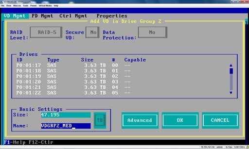
b. Create another VD on the same RAID array using the remaining size of the array. Name it as VDGRP1_MED. This should show up at ID 2. See Figure 2.
3. Repeat Step 2 for each new RAID array., naming each of the other RAID arrays as VDGRPx_VM with IDs 1,3,5 and 7 and VDGRPx_MED with IDs 2,4,6 and 8.
4. You need these IDs to map the Datastores at VM back to the actual RAID arrays and verify the setup.
Table 1
| ID |
VD |
What is it used for |
| 0 |
VDGRP_ESX |
ESXi Installed here |
| 1 |
VDGRP1_VM |
VM1_Disk |
| 2 |
VDGRP1_MED |
VM1_Media_disk |
| 3 |
VDGRP2_VM |
VM2_Disk |
| 4 |
VDGRP2_MED |
VM2_Media_disk |
| 5 |
VDGRP3_VM |
VM3_Disk |
| 6 |
VDGRP3_MED |
VM3_Media_disk |
| 7 |
VDGRP4_VM |
VM4_Disk |
| 8 |
VDGRP4_MED |
VM4_Media_disk |
Figure 1
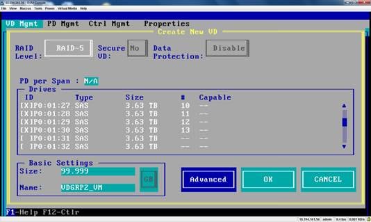
Figure 2.
Please Note - There are only 2 VDs per RAID5/6 array, one for VM and the other for media repository. There is no other VD on the array. By doing this, we are ensuring the required performance at the storage level by not overloading the array with too many writes/reads from multiple VMs.
Multiple VMs writing into the same RAID array create performance bottle necks, deteriorating the latency for read/write to disk. Poor latency results in dropped frames while writing and reading from the disk. In the snapshot of the RAID BIOS showing VDs, see that each RAID5/6 group contains only one disk for the VM and one disk for the media repository. And also by assigning more than one VM to the same RAID array, a failed array can bring down more cameras.
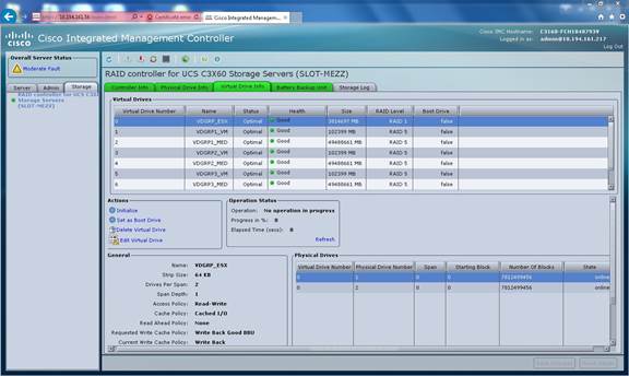
By following the convention described in table 1, the VD information will show up as follows,
The screenshots show the RAIDs and Virtual drives from CIMC interface:
Figure 3
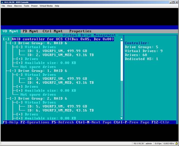
The view of the arrays from the RAID BIOS, showing Virtual Drives, which can be seen on the CIMC interface Storage tabs also. An example view is given below showing RAID 6 arrays.
Figure 4
Step 2 - Installing ESXi
Install the C3160 customized ESXi 6.0 on the VDGRP_ESX drive by following the on screen instructions. Please follow the instructions from VMWare on installing ESXi,
Step 3 - Adding Host to vCenter
If there is an existing vCenter, add this host to that vCenter. If not, please follow VMWare instructions on installing and configuring vCenter, compatible with ESXi 6.0. Install required VMWare licenses to run ESXi on the host.
Step 4 - Importing RAID Arrays into vCenter
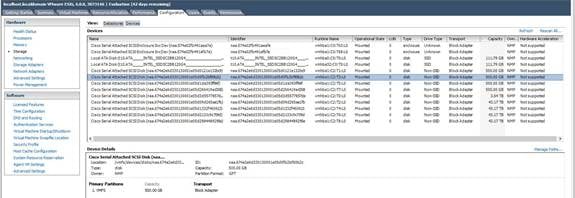
Browse on vCenter to this host, on the configuration tab, click on Storage from the list of items on the left side of the page and then click on Devices. This lists all available devices which includes the Virtual Drives that were created in Step 2. Typically, the path to the device has the following format:
The number following T in the format above matches the ID of the Virtual Drives created in Step 2. This is the key to mapping Cisco VSM VM instances to the right storage device. There may be more than one vmhba* entry in the list. And devices under only one of the vmhbaX pertains to our setup here. Always look at the size column to determine we are looking at the right devices.
A sample screenshot of the devices page is below,
Figure 5
Step 5 - Datastores
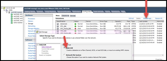
Under DataStores on the same page on vCenter, click on “Add Storage” to start adding these device as disks to deploy the Cisco VSM VM.
The path to the device on this host should show up as the following:
Where values 0-8 map to the VDs we created in Step 2 and corresponding VDs are show in table 1. Look for the size of the devices to make sure the right device is being chosen.
The suggested naming convention is as follows,
1. Add device with name T1 that is apprx 120GB in size, created to contain the VM itself, name it as VM1_disk.
2. Add device with name T2 that is approx. 43 TB (RAID6) or 47 TB (RAID 5) in size, created to contain the media repository, name it as VM1_Media_disk.
3. Now repeat steps 1 and 2 for devices with Ids T<3-8>, adding them as VMx_disk and VMx_Media_disk for the remaining VM instances.
This convention helps to track a storage device all the way down to the RAID Array.
A sample screenshot of “Add Storage” section is below:
Figure 6
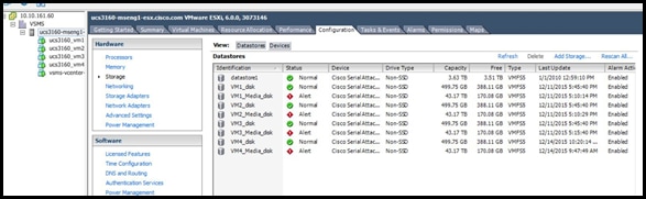
Once all devices are added, the screen will look as follows:
Figure 7
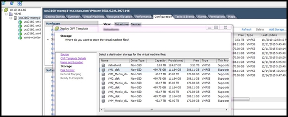
Step 6 - Deploying the OVA
When the first OVA is deployed, pick VM1_disk as the datastore. Following this convention, second OVA is deployed on data store named VM2_disk and so forth.
Figure 8
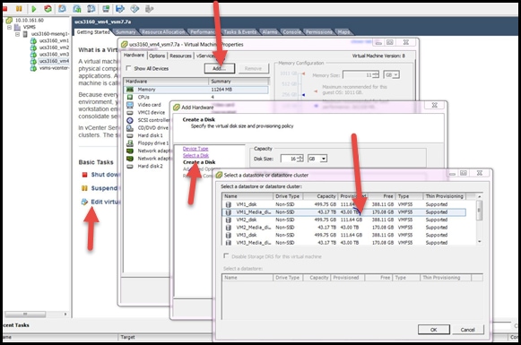
Step 7 – Adding Media Repositories to the VSM VM
Once VM is deployed, it is time to add media repositories. On the first VM, add VM1_Media_disk datastore as the hard disk. Similarly on the second VM add VM2_Media_disk as the hard disk and so forth.
By doing this, we have ensured that we are not reusing the same datastore and hence the same RAID array on more than one instances of the VSM.
Figure 9
Step 8 – Validating the Setup
Go back and verify there is only a 1 – 1 mapping between Cisco VSM instance and the underlying storage using Table 1. Make sure no two VMs use the same VD. Following the convention mentioned in Table 1 we ensure the RAID arrays are not shared across VMs.
Troubleshooting
Check latency
It is recommended that average write latency does not exceed 20 ms. If the average write latency is higher, it can show up as dropped frames by the recorder. And the cameras with dropped frames may be RED with status message indicating frame drops.
Write latency can be verified at each VM level or at the host level on the performance charts. The issue may be localized to a single VM / RAID array or to the entire RAID arrays under a host bus adapter.
Notes
THE SPECIFICATIONS AND INFORMATION REGARDING THE PRODUCTS IN THIS MANUAL ARE SUBJECT TO CHANGE WITHOUT NOTICE. ALL STATEMENTS, INFORMATION, AND RECOMMENDATIONS IN THIS MANUAL ARE BELIEVED TO BE ACCURATE BUT ARE PRESENTED WITHOUT WARRANTY OF ANY KIND, EXPRESS OR IMPLIED. USERS MUST TAKE FULL RESPONSIBILITY FOR THEIR APPLICATION OF ANY PRODUCTS.
THE SOFTWARE LICENSE AND LIMITED WARRANTY FOR THE ACCOMPANYING PRODUCT ARE SET FORTH IN THE INFORMATION PACKET THAT SHIPPED WITH THE PRODUCT AND ARE INCORPORATED HEREIN BY THIS REFERENCE. IF YOU ARE UNABLE TO LOCATE THE SOFTWARE LICENSE OR LIMITED WARRANTY, CONTACT YOUR CISCO REPRESENTATIVE FOR A COPY.
The Cisco implementation of TCP header compression is an adaptation of a program developed by the University of California, Berkeley (UCB) as part of UCB’s public domain version of the UNIX operating system. All rights reserved. Copyright © 1981, Regents of the University of California.
NOTWITHSTANDING ANY OTHER WARRANTY HEREIN, ALL DOCUMENT FILES AND SOFTWARE OF THESE SUPPLIERS ARE PROVIDED “AS IS” WITH ALL FAULTS. CISCO AND THE ABOVE-NAMED SUPPLIERS DISCLAIM ALL WARRANTIES, EXPRESSED OR IMPLIED, INCLUDING, WITHOUT LIMITATION, THOSE OF MERCHANTABILITY, FITNESS FOR A PARTICULAR PURPOSE AND NONINFRINGEMENT OR ARISING FROM A COURSE OF DEALING, USAGE, OR TRADE PRACTICE.
IN NO EVENT SHALL CISCO OR ITS SUPPLIERS BE LIABLE FOR ANY INDIRECT, SPECIAL, CONSEQUENTIAL, OR INCIDENTAL DAMAGES, INCLUDING, WITHOUT LIMITATION, LOST PROFITS OR LOSS OR DAMAGE TO DATA ARISING OUT OF THE USE OR INABILITY TO USE THIS MANUAL, EVEN IF CISCO OR ITS SUPPLIERS HAVE BEEN ADVISED OF THE POSSIBILITY OF SUCH DAMAGES.
Any Internet Protocol (IP) addresses and phone numbers used in this document are not intended to be actual addresses and phone numbers. Any examples, command display output, network topology diagrams, and other figures included in the document are shown for illustrative purposes only. Any use of actual IP addresses or phone numbers in illustrative content is unintentional and coincidental.
All printed copies and duplicate soft copies are considered un-Controlled copies and the original on-line version should be referred to for latest version.
Cisco has more than 200 offices worldwide. Addresses, phone numbers, and fax numbers are listed on the Cisco website at www.cisco.com/go/offices.
Cisco and the Cisco logo are trademarks or registered trademarks of Cisco and/or its affiliates in the U.S. and other countries. To view a list of Cisco trademarks, go to this URL: www.cisco.com/go/trademarks. Third-party trademarks mentioned are the property of their respective owners. The use of the word partner does not imply a partnership relationship between Cisco and any other company. (1110R)
© 2016 Cisco Systems, Inc. All rights reserved.
 Feedback
Contact Cisco
- Open a Support Case

- (Requires a Cisco Service Contract)