Installing the Rail System Kit for Cisco IPS 4270-20
Available Languages
Table Of Contents
Installing the Rail System for the Cisco
IPS 4270-20Space and Airflow Requirements
Installing the Security Appliance in the Rack
Extending the IPS 4270-20 from the Rack
Installing the Cable Management Arm
Converting the Cable Management Arm
Obtaining Documentation and Submitting a Service Request
Installing the Rail System for the Cisco
IPS 4270-20
Published: September 19, 2007Revised: September 14, 2012Contents
•
Space and Airflow Requirements
•
•
•
•
•
Introduction
This rail system supports a variety of products that can be installed in round-, square, or threaded-hole racks. The following illustration shows the three rack hole-types. Use Figure 1 to identify your rack type and then follow the installation steps accordingly.
Figure 1 Round-, Square-, and Threaded-Hole Racks
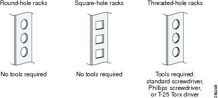
No tools are required for the round- and square-hole racks. You may need screws that fit the threaded-hole rack and a driver for those screws.You need a standard screwdriver to remove the round- and square-hole studs from the slide assemblies when you install the security appliance in a threaded-whole rack.
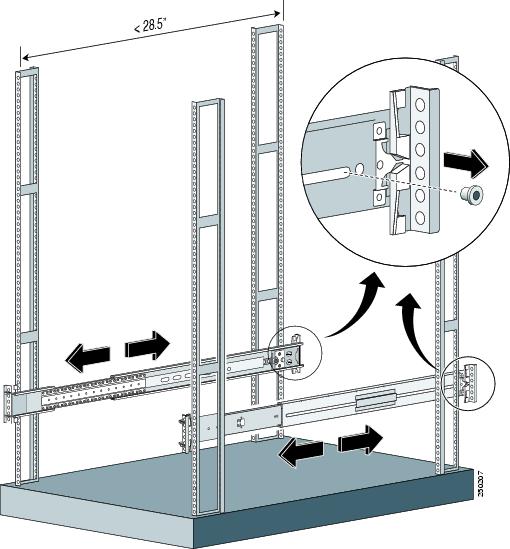
This rail system supports a minimum rack depth of 24 in. (60.96 cm) and a maximum rack depth of 36.5 in. (92.71 cm).
Rail System Kit Contents
The rail system kit contains the following items:
•
•
•
•
•
•
•
Space and Airflow Requirements
To allow for servicing and adequate airflow, follow these space and airflow requirements when choosing where to place a rack:
•
•
•
The IPS 4270-20 draws in cool air through the front and expels warm air through the back. The front and back rack doors must be adequately ventilated to allow ambient room air to enter the chassis and the back must be adequately ventilated to allow warm air to escape from the chassis.
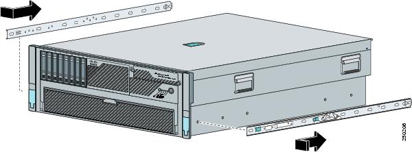
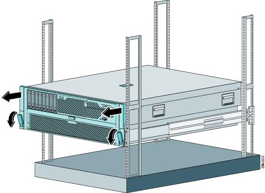
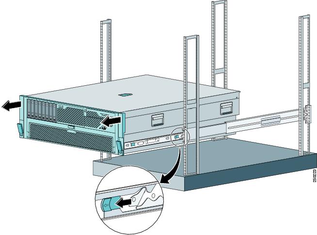
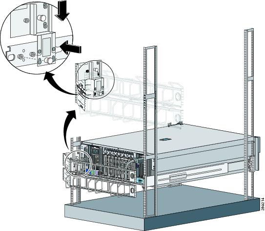
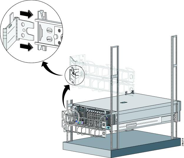
Installing the Security Appliance in the Rack
WarningTo install the IPS 4270-20 in the rack, follow these steps:
Step 1

Note
Step 2
Step 3
Step 4
Step 5
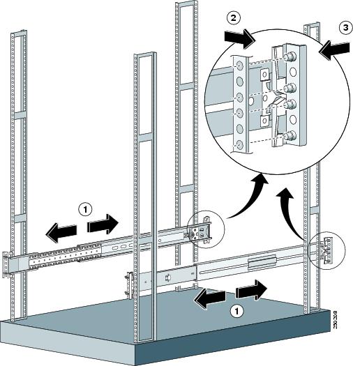
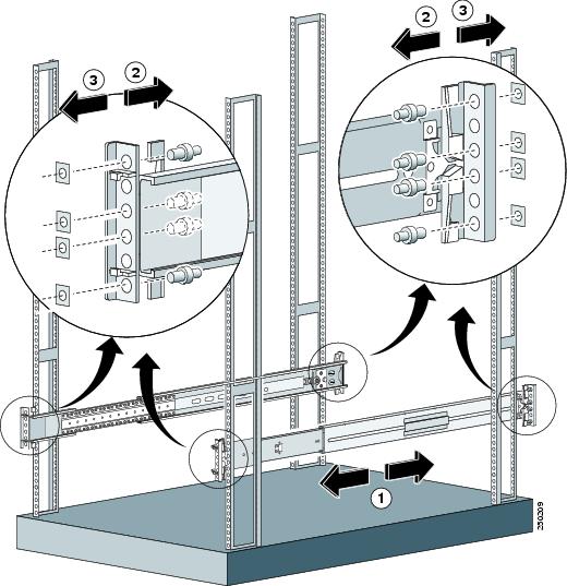
For round- and square-hole racks:
a.
b.
The spring latch locks the slide assembly into position.
c.
Make sure the slide assemblies line up with each other in the rack.
d.
For threaded-hole racks:
a.
Note
b.
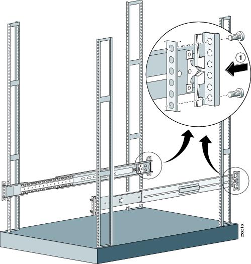
c.
Step 6
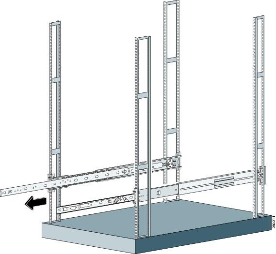
Step 7

Caution
Step 8
Note
Step 9
For information on installing connections to the IPS 4270-20, refer to "Installing the IPS 4270-20," in Installing Cisco Intrusion Prevention System Appliances and Modules 6.0.
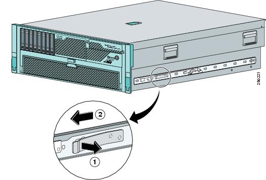
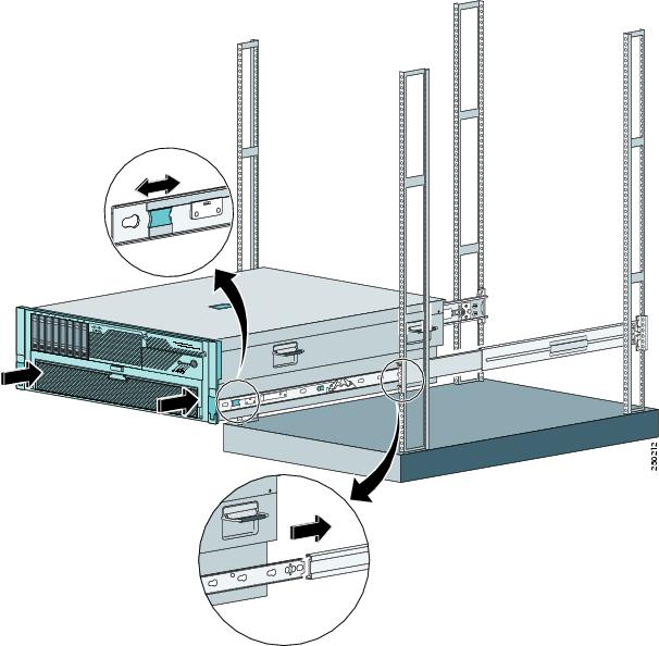
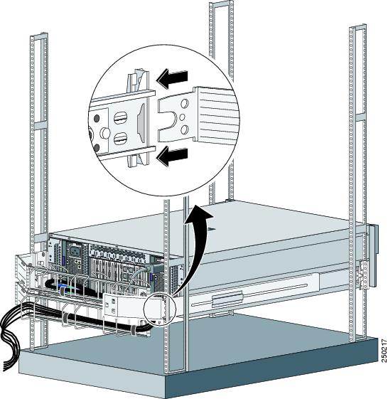
Extending the IPS 4270-20 from the Rack
You can extend the IPS 4270-20 from the rack for service or removal.
Caution
To extend the IPS 4270-20 from the rack, follow these steps:
Step 1
Note
Step 2
Step 3
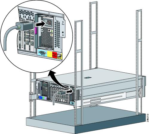
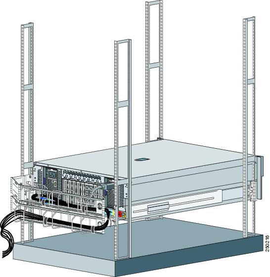
Installing the Cable Management Arm
Note
To install the cable management arm, follow these steps:
Step 1
Step 2
Caution
Note
Step 3
Note
Caution
Step 4
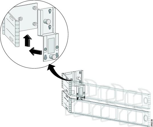
Converting the Cable Management Arm
Note
Note
To convert the cable management arm swing, follow these steps:
Step 1
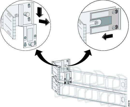
Step 2
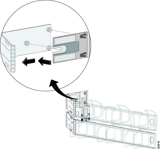
Step 3
Note
Related Documentation
You can find supporting documentation for the Cisco IPS security appliances on Cisco.com at:
http://www.cisco.com/en/US/products/hw/vpndevc/ps4077/tsd_products_support_series_home.html
Obtaining Documentation and Submitting a Service Request
For information on obtaining documentation, submitting a service request, and gathering additional information, see the monthly What's New in Cisco Product Documentation, which also lists all new and revised Cisco technical documentation, at:
http://www.cisco.com/en/US/docs/general/whatsnew/whatsnew.html
Subscribe to the What's New in Cisco Product Documentation as a Really Simple Syndication (RSS) feed and set content to be delivered directly to your desktop using a reader application. The RSS feeds are a free service and Cisco currently supports RSS Version 2.0.
This document is to be used in conjunction with the documents listed in the "Related Documentation" section.
Cisco and the Cisco logo are trademarks or registered trademarks of Cisco and/or its affiliates in the U.S. and other countries. To view a list of Cisco trademarks, go to this URL: www.cisco.com/go/trademarks. Third-party trademarks mentioned are the property of their respective owners. The use of the word partner does not imply a partnership relationship between Cisco and any other company. (1110R)
Any Internet Protocol (IP) addresses used in this document are not intended to be actual addresses. Any examples, command display output, and figures included in the document are shown for illustrative purposes only. Any use of actual IP addresses in illustrative content is unintentional and coincidental.
© 2007-2012 Cisco Systems, Inc. All rights reserved.
Printed in the USA on recycled paper containing 10% postconsumer waste.

 Feedback
Contact Cisco
- Open a Support Case

- (Requires a Cisco Service Contract)