Routed Pseudowire
Available Languages
Table Of Contents
Prerequisites for Routed Pseudowire
Restrictions for Routed Pseudowire
Information About Routed Pseudowire
How to Configure Routed Pseudowire CLI and Interface Code
Configuring Routed PseudoWire CLI and Interface Code
Configuration Examples for Routed Pseudowire and Interface Code
Feature Information for Routed Pseudowire
Routed Pseudowire
Revised: July 27, 2012, OL-25962-02First Published: July 27, 2012Last Updated: July 27, 2012This feature combines the Layer 2 forwarding with Layer 3 routing functionality and enables configuring EoMPLS and routing simultaneously on an SVI (Interface VLAN). This allows Layer 3 traffic to be routed into an EoMPLS pseudowire domain.
Finding Feature Information
Your software release may not support all the features documented in this module. For the latest feature information and caveats, see the release notes for your platform and software release. To find information about the features documented in this module, and to see a list of the releases in which each feature is supported, see the "Feature Information for Routed Pseudowire" section.
Use Cisco Feature Navigator to find information about platform support and Cisco software image support. To access Cisco Feature Navigator, go to http://www.cisco.com/go/cfn. An account on Cisco.com is not required.
Contents
•
Prerequisites for Routed Pseudowire
•
•
•
•
Prerequisites for Routed Pseudowire
•
–
–
–
–
•
–
–
–
–

Note
•
•
Restrictions for Routed Pseudowire
•
•
•
•
Information About Routed Pseudowire
Routed pseudowire (PW) is a Layer 3 interface within the ISR G2 routers. All the standard IOS Layer 3 features can be applied to this interface. This interface is not associated with any physical interface.
Routed pseudowire is created when the IP address and xconnect commands are simultaneously present on a VLAN interface. This allows Layer 3 traffic to be routed into an EoMPLS pseudowire domain.
How to Configure Routed Pseudowire CLI and Interface Code
The VPLS and SVI-based EoMPLS Routed Pseudowire Support feature makes it possible to route (Layer 3), as well as switch (Layer 2), frames for pseudowire connections between provider edge (PE) devices.
Both point-to-point PE connections, in the form of Ethernet over MPLS (EoMPLS), and multipoint PE connections, in the form or Virtual Private LAN Services (VPLS), are supported. The ability to route frames to and from these interfaces now makes it possible to terminate a pseudowire into a Layer 3 network (VPN or global) on the same router or to tunnel Layer 3 frames over a Layer 2 tunnel (EoMPLS or VPLS).
The feature supports faster network convergence in the event of a physical interface or device failure through the MPLS Traffic Engineering (MPLS-TE) and Fast Reroute (FRR) features of the network. In particular, the feature enables MPLS TE-FRR protection for Layer 3 multicast over a VPLS domain.
Configuring Routed PseudoWire CLI and Interface Code
SUMMARY STEPS
1.
2.
3.
4.
5.
6.
7.
8.
9.
10.
11.
DETAILED STEPS
Troubleshooting Tips
Use the following verification commands on PE:
•
•
Configuration Examples for Routed Pseudowire and Interface Code
Example: Routed Pseudowire
The following example shows how to configure routed pseudowire:
Sample Topology
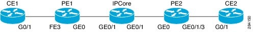
CE1 Configuration
interface GigabitEthernet0/0ip address 200.0.0.2 255.0.0.0load-interval 30duplex autorouter ospf 200network 200.0.0.0 0.255.255.255 area 0PE1 Configuration
ip vrf blueinterface Loopback1ip vrf forwarding blueip address 11.0.0.1 255.255.255.255interface Loopback0ip address 2.2.2.2 255.255.255.255interface Vlan100ip vrf forwarding blueip address 200.0.0.1 255.0.0.0load-interval 30interface Vlan300ip vrf forwarding blueip address 210.0.0.1 255.0.0.0xconnect 4.4.4.4 40 encapsulation mplsinterface FastEthernet3switchport access vlan 100no ip addressload-interval 30!interface GigabitEthernet0/0ip address 20.0.0.1 255.0.0.0load-interval 30duplex autorouter ospf 100mpls ldp autoconfig area 0network 2.2.2.2 0.0.0.0 area 0network 20.0.0.0 0.0.0.255 area 0router ospf 200 vrf bluerouter-id 11.0.0.1passive-interface Vlan100network 11.0.0.1 0.0.0.0 area 0network 200.0.0.0 0.255.255.255 area 0network 210.0.0.0 0.255.255.255 area 0IP Core Configuration
interface Loopback0ip address 3.3.3.3 255.255.255.255interface GigabitEthernet0/1ip address 20.0.0.2 255.0.0.0duplex autospeed autono keepaliveinterface GigabitEthernet0/2ip address 30.0.0.1 255.0.0.0load-interval 30duplex autospeed autono keepaliverouter ospf 100mpls ldp autoconfig area 0network 3.3.3.3 0.0.0.0 area 0network 20.0.0.0 0.0.0.255 area 0network 30.0.0.0 0.0.0.255 area 0PE 2 Configuration
ip vrf blueinterface Loopback1ip vrf forwarding blueip address 11.0.0.3 255.255.255.255interface Loopback0ip address 4.4.4.4 255.255.255.255interface Vlan100ip vrf forwarding blueip address 220.0.0.1 255.0.0.0load-interval 30interface Vlan300ip vrf forwarding blueip address 210.0.0.2 255.0.0.0xconnect 2.2.2.2 40 encapsulation mplsinterface GigabitEthernet0/0ip address 30.0.0.2 255.0.0.0load-interval 30duplex autointerface GigabitEthernet0/0/3switchport access vlan 100router ospf 100mpls ldp autoconfig area 0network 4.4.4.4 0.0.0.0 area 0network 30.0.0.0 0.0.0.255 area 0router ospf 200 vrf bluerouter-id 11.0.0.3network 11.0.0.3 0.0.0.0 area 0network 210.0.0.0 0.255.255.255 area 0network 220.0.0.0 0.255.255.255 area 0CE2 Configuration
interface GigabitEthernet0/0ip address 220.0.0.2 255.0.0.0load-interval 30duplex autorouter ospf 200network 220.0.0.0 0.255.255.255 area 0Troubleshooting Tips
Verifying RPW Status on PE Routers
PE1# show xconnect allLegend: XC ST=Xconnect State S1=Segment1 State S2=Segment2 StateUP=Up DN=Down AD=Admin Down IA=InactiveSB=Standby RV=Recovering NH=No HardwareXC ST Segment 1 S1 Segment 2 S2------+---------------------------------+--+---------------------------------+--UP ac Vl300:300(Eth VLAN) UP mpls 4.4.4.4:40 UPPE2# show xconnect allLegend: XC ST=Xconnect State S1=Segment1 State S2=Segment2 StateUP=Up DN=Down AD=Admin Down IA=InactiveSB=Standby RV=Recovering NH=No HardwareXC ST Segment 1 S1 Segment 2 S2------+---------------------------------+--+---------------------------------+--UP ac Vl300:300(Eth VLAN) UP mpls 4.4.4.4:40 UPVerifying MPLS Pseudowire OAM Ping
PE2# ping vrf blue 210.0.0.1Type escape sequence to abort.Sending 5, 100-byte ICMP Echos to 210.0.0.1, timeout is 2 seconds:!!!!!Success rate is 100 percent (5/5), round-trip min/avg/max = 1/1/1 msPE1# ping vrf blue 210.0.0.2Type escape sequence to abort.Sending 5, 100-byte ICMP Echos to 210.0.0.2, timeout is 2 seconds:!!!!!Success rate is 100 percent (5/5), round-trip min/avg/max = 1/3/4 msVerifying VRF Routing Table on PE Routers
PE1# show ip route vrf blueRouting Table: blueCodes: L - local, C - connected, S - static, R - RIP, M - mobile, B - BGPD - EIGRP, EX - EIGRP external, O - OSPF, IA - OSPF inter areaN1 - OSPF NSSA external type 1, N2 - OSPF NSSA external type 2E1 - OSPF external type 1, E2 - OSPF external type 2i - IS-IS, su - IS-IS summary, L1 - IS-IS level-1, L2 - IS-IS level-2ia - IS-IS inter area, * - candidate default, U - per-user static routeo - ODR, P - periodic downloaded static route, H - NHRP, l - LISP+ - replicated route, % - next hop overrideGateway of last resort is not set11.0.0.0/32 is subnetted, 2 subnetsC 11.0.0.1 is directly connected, Loopback1O 11.0.0.3 [110/2] via 210.0.0.2, 00:18:22, Vlan300C 200.0.0.0/8 is directly connected, Vlan100200.0.0.0/32 is subnetted, 1 subnetsL 200.0.0.1 is directly connected, Vlan100C 210.0.0.0/8 is directly connected, Vlan300210.0.0.0/32 is subnetted, 1 subnetsL 210.0.0.1 is directly connected, Vlan300O 220.0.0.0/8 [110/2] via 210.0.0.2, 00:18:22, Vlan300PE2# show ip route vrf blueRouting Table: blueCodes: L - local, C - connected, S - static, R - RIP, M - mobile, B - BGPD - EIGRP, EX - EIGRP external, O - OSPF, IA - OSPF inter areaN1 - OSPF NSSA external type 1, N2 - OSPF NSSA external type 2E1 - OSPF external type 1, E2 - OSPF external type 2i - IS-IS, su - IS-IS summary, L1 - IS-IS level-1, L2 - IS-IS level-2ia - IS-IS inter area, * - candidate default, U - per-user static routeo - ODR, P - periodic downloaded static route, H - NHRP, l - LISP+ - replicated route, % - next hop overrideGateway of last resort is not set11.0.0.0/8 is variably subnetted, 3 subnets, 2 masksC 11.0.0.0/8 is directly connected, Loopback1O 11.0.0.1/32 [110/2] via 210.0.0.1, 00:19:16, Vlan300L 11.0.0.3/32 is directly connected, Loopback1O 200.0.0.0/8 [110/2] via 210.0.0.1, 00:19:16, Vlan300C 210.0.0.0/8 is directly connected, Vlan300210.0.0.0/32 is subnetted, 1 subnetsL 210.0.0.2 is directly connected, Vlan300C 220.0.0.0/8 is directly connected, Vlan100220.0.0.0/32 is subnetted, 1 subnetsL 220.0.0.1 is directly connected, Vlan100Verifying End-to-End Ping
CE1# ping vrf blue 220.0.0.2Type escape sequence to abort.Sending 5, 100-byte ICMP Echos to 220.0.0.2, timeout is 2 seconds:!!!!!Success rate is 100 percent (5/5), round-trip min/avg/max = 1/3/4 msCE2# ping vrf blue 200.0.0.2Type escape sequence to abort.Sending 5, 100-byte ICMP Echos to 220.0.0.1, timeout is 2 seconds:!!!!!Success rate is 100 percent (5/5), round-trip min/avg/max = 1/3/4 msAdditional References
Related Documents
Standards
—
No new or modified standards are supported by this feature, and support for existing standards has not been modified by this feature.
MIBs
—
No new or modified MIBs are supported by this feature, and support for existing MIBs has not been modified by this feature.
RFCs
—
No new or modified RFCs are supported by this feature, and support for existing RFCs has not been modified by this feature.
Technical Assistance
Feature Information for Routed Pseudowire
Table 1 lists the release history for this feature.
Note
Table 1 Feature Information for Routed Pseudowire
Routed Pseudowire
15.2(3)T
15.2(4)MIn Cisco IOS Release 15.2(3)T and Cisco IOS Release 15.2(4)M, this feature was introduced on Cisco ISR G2s. For more information about the Prerequisites, see the "Prerequisites for Routed Pseudowire" section.
Cisco and the Cisco logo are trademarks or registered trademarks of Cisco and/or its affiliates in the U.S. and other countries. To view a list of Cisco trademarks, go to this URL: www.cisco.com/go/trademarks. Third-party trademarks mentioned are the property of their respective owners. The use of the word partner does not imply a partnership relationship between Cisco and any other company. (1110R)
Any Internet Protocol (IP) addresses and phone numbers used in this document are not intended to be actual addresses and phone numbers. Any examples, command display output, network topology diagrams, and other figures included in the document are shown for illustrative purposes only. Any use of actual IP addresses or phone numbers in illustrative content is unintentional and coincidental.
© 2012 Cisco Systems, Inc. All rights reserved.
 Feedback
Contact Cisco
- Open a Support Case

- (Requires a Cisco Service Contract)
This Document Applies to These Products
- Collaboration Endpoints - Retired Products
- Conferencing - Retired Products
- Contact Center - Retired Products
- Optical Networking - Retired Products
- Routers - Retired Products
- Security - Retired Products
- Servers - Unified Computing (UCS) Retired Products
- Storage Networking Retired Products
- Switches - Retired Products
- Video - Retired Products
- Wireless - Retired Products