Cisco 7200 Rack Density System (RDS) Installation Instructions
Available Languages
Table Of Contents
Cisco 7200 Rack Density System (RDS) Installation Instructions
Installation Steps for the Cisco 7200 RDS
Electrical Equipment Guidelines
Powering Down the Router and Disconnecting Input Power
Uninstalling Routers from the Rack and Removing Brackets
Uninstalling Routers from the Existing Rack
Removing Rack-Mounting Brackets from the Router
Installing Flanges and Spacer on the Router
Installing Front-Mounting Flanges on the Router
Installing the Rear Spacer on the Router
Assembling the Mounting Flanges on the RDS
Installing the RDS in the Rack
Mounting Filler Panels in the RDS
Reconnecting Input Power and Powering Up the Router
Obtaining Technical Assistance
Cisco 7200 Rack Density System (RDS) Installation Instructions
Product Number: CISCO7200RDS
Document Version History
The document version history is in Table 1.
Table 1 Document Version History
78-11310-04
October, 2005
This document version adds warning statement numbers.
Introduction
The Cisco 7200 Rack Density System (RDS) is a sheet-metal assembly used to organize Cisco 7206 VXR routers vertically into a rack. The main function of the RDS is to change the airflow from side-to-side to front-to-back. When routers are mounted horizontally in a rack, air flows sideways between the racks. Vertical mounting of routers prevents overheating in the last rack in a series of racks.
Objectives
The purpose of this document is to explain how to perform the following procedures:
•
Assemble mounting flanges on the RDS
•
•
Contents
This document includes the following sections:
•
•
•
•
•
•
•
•
Related Documentation
For more information, refer to the following resource:
For hardware installation and maintenance information on the Cisco 7206 VXR routers, refer to the Cisco 7200 VXR Installation and Configuration Guide that shipped with your router.
Cisco 7200 RDS Overview
The Cisco 7200 Rack Density System (RDS) is a sheet-metal assembly designed to arrange Cisco 7206 VXR routers vertically in a rack. The RDS is suitable for most EIA or ETSI 19-inch, seven-foot high
or six-foot high, four-post racks. You can purchase optional rack-mounting brackets for wider racks.The RDS mounts in the rack in any one of eight configurations, depending on front orientation or reverse orientation. Up to three RDSs can be mounted in most typical seven foot equipment racks with at least 40 usable rack units (RUs) for EIA racks, or 69 usable RUs for ETSI racks.
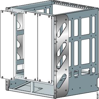
Each RDS accommodates up to three Cisco 7206 VXR routers and/or filler panels, mounted vertically.
Figure 1 Fully Populated Cisco 7200 RDS
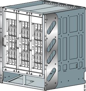
The Cisco 7200 RDS is available as a single field-replaceable unit (FRU) (part number CISCO7200RDS).
Installation Steps for the Cisco 7200 RDS
For existing routers:
•
•
•
•
For Cisco 7200 RDS:
•
•
•

Note
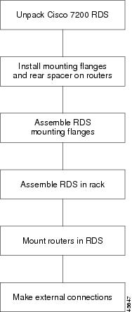
Cisco 7200 RDS Flowchart
A flowchart of the steps to assemble the RDS, install it in a rack and mount the Cisco 7206 VXR routers in it follows.
Figure 2 Installation Flowchart
Installation Prerequisites
This section includes the following guidelines:
•
•
•
Tools and Parts Required
The RDS comes with the hardware to install front-mounting flanges and a rear spacer on Cisco 7206 VXR routers, mounting flanges on the RDS, and to mount up to three Cisco 7206 VXR routers and/or filler panels. You will need the following parts and tools. If you need additional equipment, contact a service representative for ordering information.
Parts and Tools Needed
•
•
For the RDS:
•
•
•
For Cisco 7206 VXR routers:
•
•
•
•
Tools and Parts Required But Not Supplied
•
•
•
Optional Equipment (see your service representative for ordering):
•
•
Safety Guidelines
Following are safety guidelines that you should follow when working with any equipment that connects to electrical power or telephone wiring.

Warning
Statement 1030
Electrical Equipment Guidelines
Follow these basic guidelines when working with any electrical equipment:
•
•
•
•
•
•
Telephone Wiring Guidelines
Use the following guidelines when working with any equipment that is connected to telephone wiring
or to other network cabling:
•
•
•
•
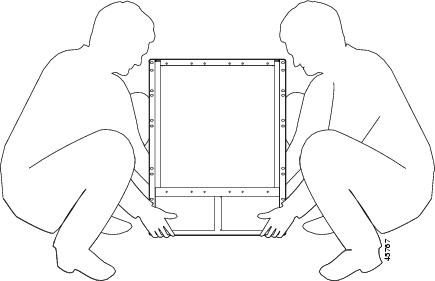
RDS Lifting Guidelines
An unpopulated Cisco 7200 RDS weighs 33 pounds. A fully populated Cisco 7200 RDS with three routers weighs approximately 170 pounds. To avoid problems with lifting, you should install the RDS in a rack before mounting routers. Ensure that the rack is placed in a position where your site is properly prepared, so you avoid having to move it later to accommodate power sources and network connections.
Warning
Whenever you lift the RDS or any heavy object, follow these guidelines (see Figure 3):
•
•
•
•
Figure 3 Lifting an Unpopulated Cisco 7200 RDS Chassis
Warning
Warning
Cisco 7200 RDS Considerations
The Cisco 7200 RDS is suitable for most 19-inch, seven-foot high or six-foot high, four-post racks. You can purchase optional rack-mounting brackets for wider racks. Up to three RDSs can be mounted in most typical seven-foot equipment racks with at least 40 usable rack units (RUs) for EIA racks, or 69 usable RUs for ETSI racks.
Each RDS permits a maximum of three routers and/or filler panels.
Using the hardware provided with your Cisco 7200 RDS, consider the following guidelines:
•
•
•
•
When planning to install the RDS in your rack, consider the following:
•
•
•
•
•
Warning

Caution
Powering Down the Router and Disconnecting Input Power
If your router is already installed on a tabletop or workbench, or in a rack, you must power down the router and disconnect input power before attempting to mount it in the RDS.
The purpose of this section is to explain the following procedures:
•
•
•
Caution
Powering Down the Router
To power down Cisco 7206 VXR routers, complete the following steps:
Note
Step 1
Step 2
•
•
•
•
This completes the procedure for powering down Cisco 7206 VXR routers.
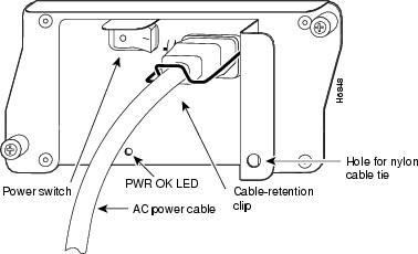
Disconnecting AC-Input Power
To disconnect AC-input power to Cisco 7206 VXR routers, complete the following steps:
Step 1
Step 2
Step 3
Figure 4 Cisco 7200 Series AC-Input Power Supply
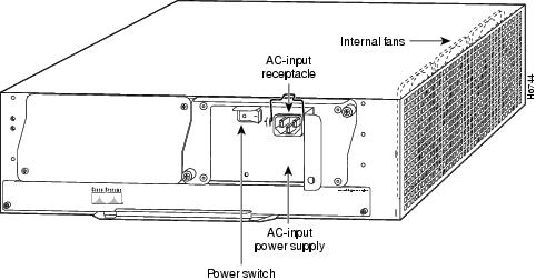
Step 4
This completes the procedure for disconnecting AC-input power to Cisco 7206 VXR routers.
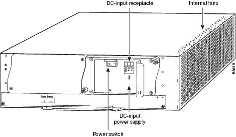
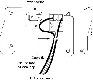
Disconnecting DC-Input Power
To disconnect DC-input power to Cisco 7206 VXR routers, complete the following steps:
Warning
Warning
Step 1
Step 2
Note
Step 3
Note
Figure 5 Cisco 7200 Series DC-Input Power Supply
Step 4
This completes the procedure for disconnecting DC-input power to the Cisco 7206 VXR routers.
Uninstalling Routers from the Rack and Removing Brackets
If your router is already installed in a rack with rack-mounting brackets, you must first remove the rack-mounting brackets from the chassis. If you are installing new routers, proceed to the "Installing Flanges and Spacer on the Router" section.
Parts and tools required for installing the RDS are listed in the "Tools and Parts Required" section.
The purpose of this section is to explain the following procedures:
•
•
Uninstalling Routers from the Existing Rack
This section describes how to uninstall the router from the rack.
Step 1
Step 2
Step 3
Step 4
Note
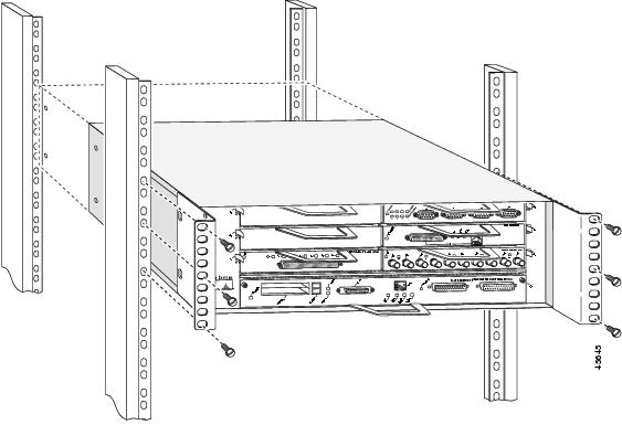
Figure 6 Uninstalling Routers from the Rack
This completes the procedure for uninstalling the router from the rack.
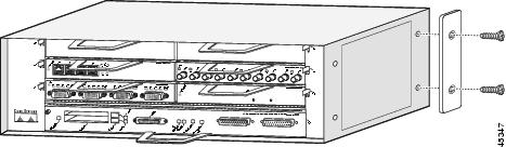
Removing Rack-Mounting Brackets from the Router
This section describes how to remove rack-mounting brackets from existing routers.
Step 1
Step 2
Figure 7 Removing Rack-Mounting Brackets from the Router
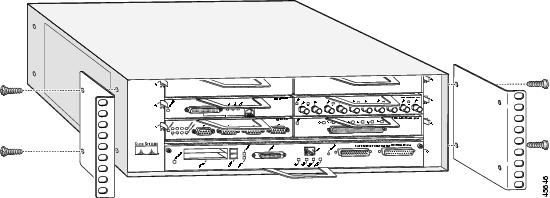
15
This completes the procedure for removing rack-mounting brackets from the router.
Installing Flanges and Spacer on the Router
After uninstalling the router from the rack and removing the brackets, the next step is to install the new front-mounting flanges and rear spacer on the router.
Installing Front-Mounting Flanges on the Router
To install the front-mounting flanges on the front sides of the router, complete the following steps:
Step 1
Step 2
Figure 8 Installing the Front-Mounting Flanges on a Cisco 7200 Series Router
(Cisco 7206 VXR Shown)
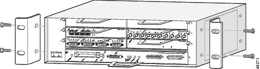
Step 3
Note
This completes the procedure for installing the front-mounting flanges on the router.
Installing the Rear Spacer on the Router
After installing the front-mounting flanges on the router, you mount a rear spacer to the right rear side of the router.
To install the rear spacer, complete the following steps:
Step 1
Step 2
Step 3
Figure 9 Installing the Rear Spacer on a Cisco 7200 Series Router (Cisco 7206VXR Shown)
This completes the rear spacer installation procedure.
Assembling the Mounting Flanges on the RDS
In this section, you will first determine which mounting configuration is appropriate for your needs, and then assemble the mounting flanges on the RDS (see Figure 10). The RDS was designed for eight mounting configurations, four based on front orientation and four based on reverse orientation.
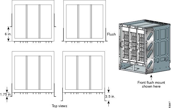
The four front-mounting configurations are (see Figure 11):
•
•
•
•
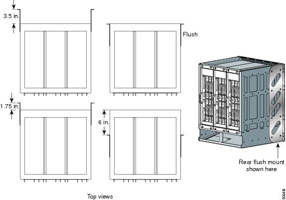
The four reverse mounting configurations are (seeFigure 12):
•
•
•
•
You must install both mounting flanges before mounting the RDS in the rack. To install the mounting flanges on the RDS, complete the following steps according to the orientation of the RDS.
Warning
Warning
Warning
Figure 10 Assembling the Mounting Flanges on the RDS
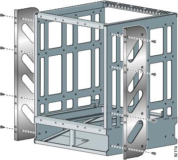
Figure 11 Four Front-Mounting Configurations
Note
Figure 12 Four Reverse-Mounting Configurations
Front Mounting Assembly
To install the mounting flanges for reverse orientation, proceed to the "Reverse Mounting Assembly" section.
Note
To install the mounting flanges for front orientation, complete the following steps:
Step 1
Step 2
Step 3
Step 4
Step 5
Figure 13 Front Mounting, Flush (Note: The Cisco 7206 VXR routers will be installed later.)
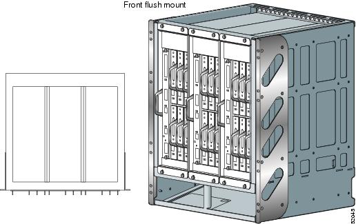
Figure 14 Front Mounting, Recessed 1-3/4 Inch (Note: The Cisco 7206 VXR routers will be
installed later.)
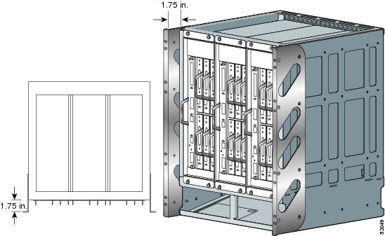
Figure 15 Front Mounting, Recessed 3-1/2 Inch (Note: The Cisco 7206 VXR routers will be
installed later.)

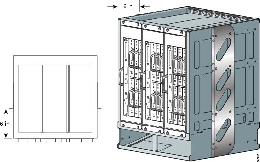
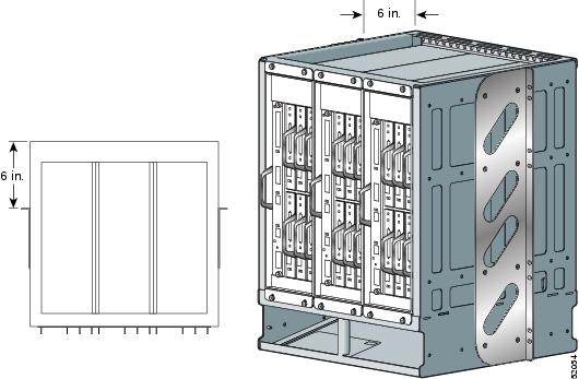
Figure 16 Front Mounting, Recessed 6 Inches (Note: The Cisco 7206 VXR routers will be
installed later.)
This completes the procedure for installing the mounting flanges for front orientation.
Reverse Mounting Assembly
To install the mounting flanges for reverse mounting, complete the following steps:
Step 1
Step 2
Step 3
If you want the front of the chassis recessed in the rack, align the mounting flange according to the amount of the recession.
Step 4
Step 5
Figure 17 Reverse Mounting, Flush (Note: The Cisco 7206 VXR routers will be installed later.)
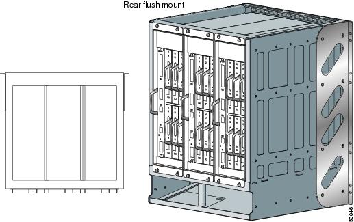
Figure 18 Reverse Mounting, Recessed 1-3/4 Inches (Note: The Cisco 7206 VXR routers will be installed later.)
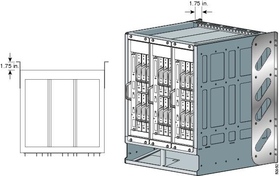
Figure 19 Reverse Mounting, Recessed 3-1/2 Inches (Note: The Cisco 7206 VXR routers will be installed later.)
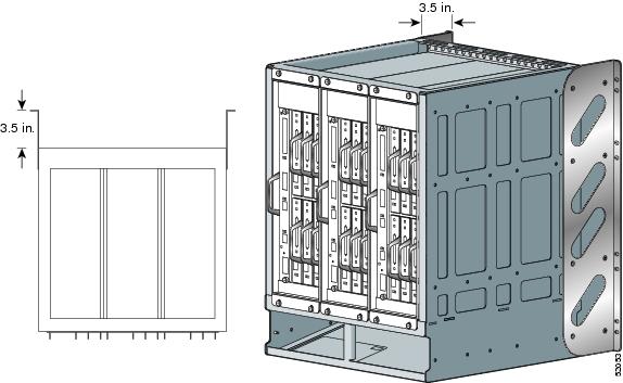
Figure 20 Reverse Mounting, Recessed 6 Inches (Note: The Cisco 7206 VXR routers will be installed later.)
This completes the procedure for installing the mounting flanges for reverse orientation.
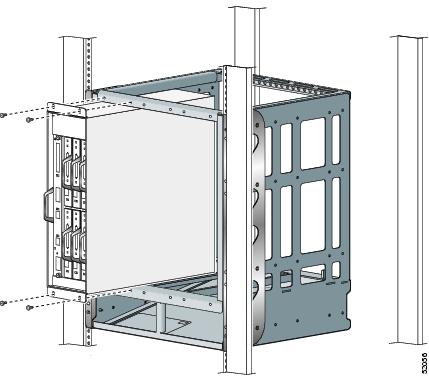
Installing the RDS in the Rack
The next step in the installation process is mounting the RDS in a rack. Hardware is not included for this step; however, if you are using Cisco 7206 VXR routers that were previously installed in a rack, you can use that same hardware.
Some equipment racks provide a power strip along the length of one of the mounting strips. If your rack has a power strip, consider the position of the strip when planning the location of the RDS. If the power strip impairs a reverse-mounting installation, remove the power strip before installing the RDS in the rack, and then replace it after the RDS is installed.
Warning
Before you mount the RDS in the rack, determine how many RDSs you will be installing, and consider any other equipment you intend to place in the rack. Install the first and any subsequent RDSs as close to the bottom of the rack as possible to maintain a low center of gravity and avoid tipping the rack.
Note
Warning
Complete the following steps to install the RDS in a rack:
Step 1
Step 2
Step 3
Step 4
Step 5
Note
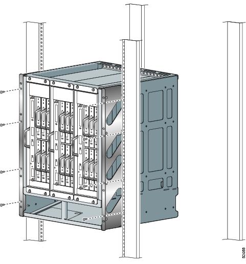
Figure 21 Installing the RDS in a Four-Post Rack (Note: The Cisco 7206 VXR routers will be installed later.)
This completes the procedure for installing the RDS in the rack.
Mounting Routers in the RDS
The next step in the procedure is to mount the Cisco 7206 VXR routers in the RDS. The routers mount vertically, attaching to the top and bottom front mounting strips of the RDS. Using the twelve panhead #8-32 x 1/2 Phillips screws with washers attached (four per router), mount the router by securing two of the screws to the upper mounting strip and two to the lower mounting strip of the RDS. Be sure to install the router with the correct side facing up, as indicated by the up arrow on the RDS. When facing the RDS, mount the first router in the left position. Subsequent routers can be mounted in the center and right positions (slot 2 and slot 3 of the RDS). Because the mounting strips support the weight of the entire router, be sure to use all four panhead #8-32 x 1/2 Phillips screws with washers attached, to fasten the router to the RDS.
Warning
Caution
Note
Warning
Complete the following steps to mount a router in the RDS:
Step 1
Step 2
Step 3
Step 4
Step 5
Step 6
Figure 22 Mounting a Cisco 7206 VXR router in the RDS
This completes the procedure for mounting the routers in the RDS.
Mounting Filler Panels in the RDS
In this step, you will install a filler panel in a blank slot of the RDS. Installation of filler panels in unpopulated slots is not required. Contact a service representative to order a filler panel (part number MAS-72RDS-KBLANK). If you decide to leave the blank slots empty, proceed to the"Reconnecting Input Power and Powering Up the Router" section.
Complete the following steps to mount filler panels in the RDS:
Step 1
Step 2
Step 3
Step 4
Step 5
Figure 23 Mounting Filler Panels in the RDS
This completes the procedure for mounting filler panels in the RDS.
Reconnecting Input Power and Powering Up the Router
The following procedures explain how to reconnect AC-input and DC-input power to Cisco 7206 VXR routers, power up the router, and verify a successful system boot.
Warning
Reconnecting AC-Input Power
To reconnect AC-input power to a Cisco 7206 VXR router, complete the following steps:
Step 1
Step 2
Step 3
Figure 24 Connecting AC-Input Power to Cisco 7206 VXR routers
Step 4
Note
Step 5
This completes the steps for reconnecting AC-input power to a Cisco 7206 VXR router.
Reconnecting DC-Input Power
To reconnect DC-input power to Cisco 7206 VXR routers, complete the following steps:
Note
Warning
Warning
Step 1
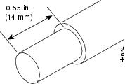
Step 2
Figure 25 Stripping the DC-Input Leads
Step 3
Step 4
Figure 26 Connecting DC-Input Power
Step 5
Note
Note
The preceding values are absolute maximum values. Typical system configurations use substantially less. To obtain typical values for your configuration, contact your Cisco sales representative.
This product relies on the building's installation for short-circuit (overcurrent) protection. Ensure that a listed and certified fuse or circuit breaker, 35A minimum 60 VDC, is used on all current-carrying conductors. Site wiring and circuit breakers need to be sized to accommodate the maximum values for safety reasons.
Step 6
Step 7
This completes the steps for reconnecting DC-input power to Cisco 7206 VXR routers.
Powering Up the Router
To power up Cisco 7206 VXR routers that have an installed AC-input or DC-input power supply, complete the following steps:
Caution
Step 1
•
•
•
•
•
•
•
•
•
Step 2
Step 3
Step 4
Step 5
Cisco Internetwork Operating System SoftwareIOS (tm) 7200 Software (C7200-J-M), Version 11.1(9) [kpfjrgiu 100]Copyright (c) 1986-1996 by cisco Systems, Inc.Compiled Sun 21-Apr-96 04:10 by
This completes the procedures for powering up the router.
Obtaining Documentation
The following sections explain how to obtain documentation from Cisco Systems.
World Wide Web
You can access the most current Cisco documentation on the World Wide Web at the following URL:
Translated documentation is available at the following URL:
http://www.cisco.com/public/countries_languages.shtml
Documentation CD-ROM
Cisco documentation and additional literature are available in a Cisco Documentation CD-ROM package, which is shipped with your product. The Documentation CD-ROM is updated monthly and may be more current than printed documentation. The CD-ROM package is available as a single unit or through an annual subscription.
Ordering Documentation
Cisco documentation is available in the following ways:
•
http://www.cisco.com/cgi-bin/order/order_root.pl
•
http://www.cisco.com/go/subscription
•
Documentation Feedback
If you are reading Cisco product documentation on Cisco.com, you can submit technical comments electronically. Click Leave Feedback at the bottom of the Cisco Documentation home page. After you complete the form, print it out and fax it to Cisco at 408 527-0730.
You can e-mail your comments to bug-doc@cisco.com.
To submit your comments by mail, use the response card behind the front cover of your document, or write to the following address:
Cisco Systems
Attn: Document Resource Connection
170 West Tasman Drive
San Jose, CA 95134-9883We appreciate your comments.
Obtaining Technical Assistance
Cisco provides Cisco.com as a starting point for all technical assistance. Customers and partners can obtain documentation, troubleshooting tips, and sample configurations from online tools by using the Cisco Technical Assistance Center (TAC) Web Site. Cisco.com registered users have complete access to the technical support resources on the Cisco TAC Web Site.
Cisco.com
Cisco.com is the foundation of a suite of interactive, networked services that provides immediate, open access to Cisco information, networking solutions, services, programs, and resources at any time, from anywhere in the world.
Cisco.com is a highly integrated Internet application and a powerful, easy-to-use tool that provides a broad range of features and services to help you to
•
•
•
•
•
You can self-register on Cisco.com to obtain customized information and service. To access Cisco.com, go to the following URL:
Technical Assistance Center
The Cisco TAC is available to all customers who need technical assistance with a Cisco product, technology, or solution. Two types of support are available through the Cisco TAC: the Cisco TAC Web Site and the Cisco TAC Escalation Center.
Inquiries to Cisco TAC are categorized according to the urgency of the issue:
•
•
•
•
Which Cisco TAC resource you choose is based on the priority of the problem and the conditions of service contracts, when applicable.
Cisco TAC Web Site
The Cisco TAC Web Site allows you to resolve P3 and P4 issues yourself, saving both cost and time. The site provides around-the-clock access to online tools, knowledge bases, and software. To access the Cisco TAC Web Site, go to the following URL:
All customers, partners, and resellers who have a valid Cisco services contract have complete access to the technical support resources on the Cisco TAC Web Site. The Cisco TAC Web Site requires a Cisco.com login ID and password. If you have a valid service contract but do not have a login ID or password, go to the following URL to register:
http://www.cisco.com/register/
If you cannot resolve your technical issues by using the Cisco TAC Web Site, and you are a Cisco.com registered user, you can open a case online by using the TAC Case Open tool at the following URL:
http://www.cisco.com/tac/caseopen
If you have Internet access, it is recommended that you open P3 and P4 cases through the Cisco TAC Web Site.
Cisco TAC Escalation Center
The Cisco TAC Escalation Center addresses issues that are classified as priority level 1 or priority level 2; these classifications are assigned when severe network degradation significantly impacts business operations. When you contact the TAC Escalation Center with a P1 or P2 problem, a Cisco TAC engineer will automatically open a case.
To obtain a directory of toll-free Cisco TAC telephone numbers for your country, go to the following URL:
http://www.cisco.com/warp/public/687/Directory/DirTAC.shtml
Before calling, please check with your network operations center to determine the level of Cisco support services to which your company is entitled; for example, SMARTnet, SMARTnet Onsite, or Network Supported Accounts (NSA). In addition, please have available your service agreement number and your product serial number.
This document is to be used in conjunction with the documents listed in the "Related Documentation" section of this document.

Copyright © 2003 Cisco Systems, Inc. All rights reserved.


 Feedback
Contact Cisco
- Open a Support Case

- (Requires a Cisco Service Contract)