Cisco NCS 4216 Hardware Installation Guide
Bias-Free Language
The documentation set for this product strives to use bias-free language. For the purposes of this documentation set, bias-free is defined as language that does not imply discrimination based on age, disability, gender, racial identity, ethnic identity, sexual orientation, socioeconomic status, and intersectionality. Exceptions may be present in the documentation due to language that is hardcoded in the user interfaces of the product software, language used based on RFP documentation, or language that is used by a referenced third-party product. Learn more about how Cisco is using Inclusive Language.
- Updated:
- November 17, 2016
Chapter: Installing the Cisco NCS 4216
- Prerequisites
- Installing the Router in a Rack
- Installing the Chassis Ground Connection
- Installing the Fan Tray
- RSP Installation
- Interface Module Installation
- Installing the Power Supply
- Connecting the Cisco NCS 4216 Router to the Network
- Connecting to the Auxiliary Port
- Connecting a Management Ethernet Cable
- Installing and Removing SFP
- Connecting a USB Flash Device
- Connecting Timing Cables
Installing the Cisco NCS 4216
This chapter describes how to install the Cisco NCS 4216.
- Prerequisites
- Installing the Router in a Rack
- Installing the Chassis Ground Connection
- Installing the Fan Tray
- RSP Installation
- Interface Module Installation
- Installing the Power Supply
- Connecting the Cisco NCS 4216 Router to the Network
Prerequisites
Before installing the Cisco NCS 4216, it is important to prepare for the installation by:
- Preparing the site (site planning) and reviewing the installation plans or method of procedures (MOP)
- Unpacking and inspecting the Cisco NCS 4216
- Gathering the tools and test equipment required to properly install the Cisco NCS 4216
For more instructions on how to prepare for the installation of the Cisco NCS 4216, see the Preparing for Installation section.
Installing the Router in a Rack
The sections describe how to install the Cisco NCS 4216 in a rack.
 Note | The Cisco NCS 4216 Door is not displayed in the figures below. It is only displayed in the Installing the Cisco NCS 4216 Door figure. |
- Installing the Chassis Brackets
- Installing the Air Plenum (A907-F2B-AIR) in the Rack
- Installing the Router Chassis in the Rack
- Installing the Cisco NCS 4216 Door
- Installing the Patch Panel on the Rack
Installing the Chassis Brackets
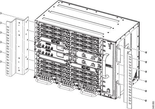
The chassis is shipped with mounting brackets that can be installed on the front or rear of the chassis. To install the brackets on the front of the chassis, perform these steps:
1. Remove the rack-mount brackets from the accessory kit and position them beside the router chassis.
2. Position one of the brackets against the chassis side, and align the screw holes.
3. Secure the bracket to the chassis with the screws removed when performing Step 1 . The recommended maximum torque is 28 in.-lb (3.16 N-m).
DETAILED STEPS
What to Do Next
Repeat Step 2 and Step 3 for the other bracket.
Installing the Air Plenum (A907-F2B-AIR) in the Rack
This procedure installs the air plenum to orient the air flow in front-to- back direction in the NCS 4216 router.
 Warning | Before performing any of the following procedures, ensure that power is removed from the DC circuit. Statement 1074 |
Warning | This equipment is intended to be grounded. Ensure that the host is connected to earth ground during normal use. Statement 39 |
Note | For nominal voltage of -60 VDC, the input voltage range is from -40 to -72 VDC. |
Note | Use only the fastening hardware provided with the NCS 4216 to prevent loosening, deterioration, and electromechanical corrosion of the hardware and joined material. |
Warning | When installing or replacing the unit, the ground connection must always be made first and disconnected last. Statement 1046 |
Warning | The Air Plenum is installed on a rack or a cabinet using thread-forming screws that remove any paint or non-conductive coatings inside the hole threads, and establish a metal-to-metal contact. Also, clean both surfaces outside the screw points that come in contact, so that they are free of paint and other nonconductive coating. Apply an appropriate antioxidant compound to the surfaces. |
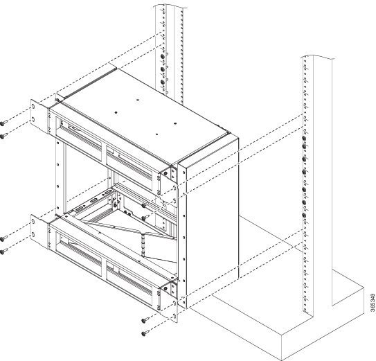
Installing Air Plenum in NCS 4216 Shelf for ANSI 23-inch Configuration
To install the Air Plenum in NCS 4216 Shelf for ANSI 23-inch configuration, follow the steps below:
1. Install the ANSI 23-inch adapter plates on the horizontal air plenums.
2. Align the screws to fix the adapter plates to the shelf. Insert the screws and tighten them to a torque value of 11.5 in-lb (1.3 N-m).
3. Place a horizontal air plenum as the base.
4. Install the vertical air plenum to the left of the bottom horizontal plenum.
5. Install the wing head screws from the internal side of the horizontal plenum and tighten the screws to a torque value of 11.5 in-lb (1.3 N-m).
6. Install the vertical air plenum to the right of the horizontal air plenum. Follow step 5.
7. Install the horizontal air plenum above the vertical air plenums. Follow step 5.
8. Install the pre-assembled air plenum for ANSI 23-inch configuration.
9. Install the pre-assembled air plenums in the ANSI 23-inch rack or cabinet.
10. Check the length between the top and bottom horizontal air plenums where the chassis will be installed. The length must be not less than 10.5 inches (267 mm). If the length is less, adjust the position of the top horizontal plenum.
11. Install the empty NCS 4216 chassis between the horizontal plenums.
DETAILED STEPS
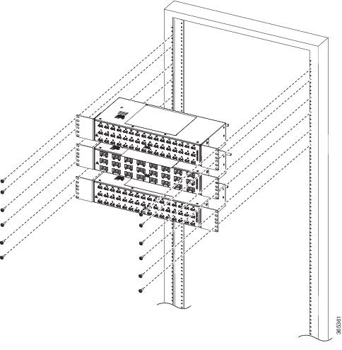
Installing the Router Chassis in the Rack
The procedures in this section apply to both horizontal and vertical mounting of the router in a rack.
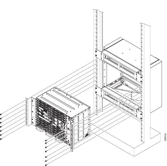
To install the router chassis in the equipment rack, perform these steps:
1. Position the chassis in the rack as follows:
2. Align the mounting holes in the bracket (and optional cable guide) with the mounting holes in the equipment rack.
3. Install the 8 or 12 (4 or 6 per side) rack mount screws through the holes in the bracket and into the threaded holes in the equipment rack posts.
4. Use a tape measure and level to verify that the chassis is installed straight and level.
DETAILED STEPS
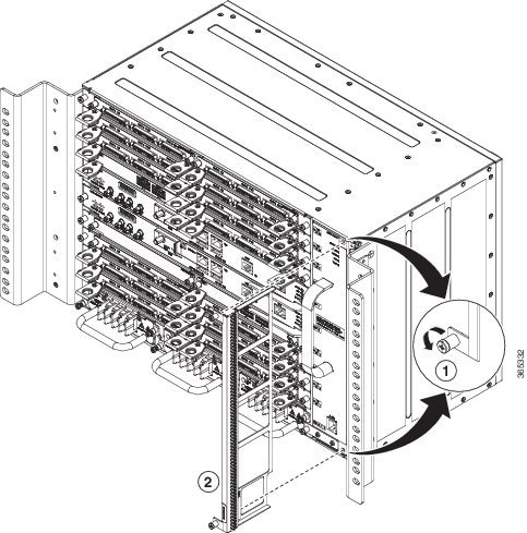
Installing the Cisco NCS 4216 Door
This section describes how to install the NCS 4216 door.
Note | You cannot install the 19-inch Rack Door. |
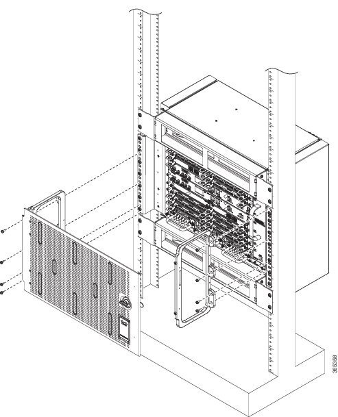
To install the door of NCS 4216 shelf, follow the steps below:
1. Align the left door bracket screw holes against the shelf screw holes.
2. Insert the fasteners provided along with the packaging (three screws on the side and two screws on the bottom of the door bracket) and tighten them to a torque value of 11.5 in-lb (1.3 N-m).
3. Place a safety washer on the front bottom of the door bracket and fasten it with a fastener.
4. Repeat steps 1 and 2 for the door bracket on the opposite side.
5. Pull the top hinge pin down on the door.
6. Align the door hinges with the bracket hinges.
7. Slide the bottom hinge pin into the bracket hinge and move the top hinge pin in the upward direction.
8. Connect the other end of the ground strap cable to a grounding point on the door bracket using a fastener.
DETAILED STEPS
| Step 1 | Align the left door bracket screw holes against the shelf screw holes. | ||
| Step 2 | Insert the fasteners provided along with the packaging (three screws on the side and two screws on the bottom of the door bracket) and tighten them to a torque value of 11.5 in-lb (1.3 N-m). | ||
| Step 3 | Place a safety washer on the front bottom of the door bracket and fasten it with a fastener. | ||
| Step 4 | Repeat steps 1 and 2 for the door bracket on the opposite side. | ||
| Step 5 | Pull the top hinge pin down on the door.
| ||
| Step 6 | Align the door hinges with the bracket hinges. | ||
| Step 7 | Slide the bottom hinge pin into the bracket hinge and move the
top hinge pin in the upward direction.
| ||
| Step 8 | Connect the other end of the ground strap cable to a grounding point on the door bracket using a fastener. |
Opening and Removing the Door of the NCS 4216 Shelf
This procedure opens and removes the door of the NCS 4216 shelf.
Note | The NCS 4216 shelf has an ESD plug input and is shipped with an ESD wrist strap. The ESD plug input is located on the outside of the shelf on the right side. It is labeled “ESD” on the top and bottom. Always wear an ESD wrist strap and connect the strap to the ESD plug when working on the NCS shelf. |
To open and remove the door of the NCS 4216 router, follow the steps below:
1. Turn the knob to unlock the door.
2. Swing the door open.
3. Remove the ground cable from the shelf by removing the screw.
4. Pull the top hinge pin holding the door to the chassis, in the downward direction.
5. Lift the door out of the bottom hinge pin to remove the door from its hinges.
DETAILED STEPS
| Step 1 | Turn the knob to unlock the door. |
| Step 2 | Swing the door open. |
| Step 3 | Remove the ground cable from the shelf by removing the screw. |
| Step 4 | Pull the top hinge pin holding the door to the chassis, in the downward direction. |
| Step 5 | Lift the door out of the bottom hinge pin to remove the door from its hinges. |
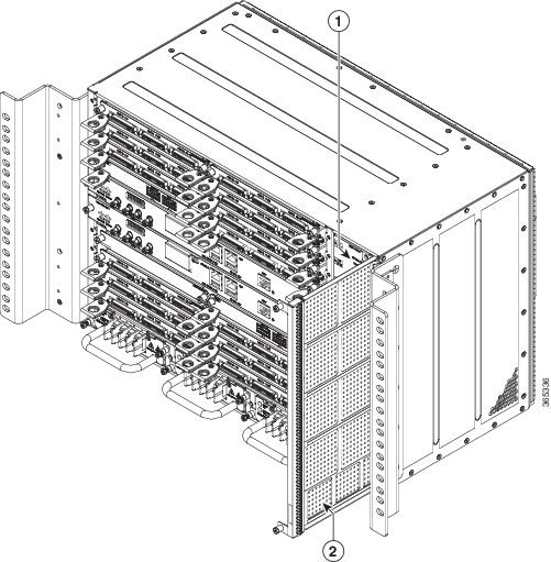
Installing the Patch Panel on the Rack
This procedure installs the Patch Panel on the Rack.
1. Assemble the patch panels on the opposite side of the rack to make the cable routing process easy.
2. Fix one patch panel with a minimum of two screws on each side.
DETAILED STEPS
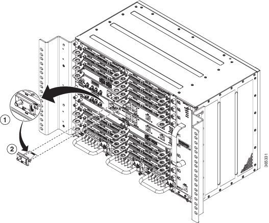
Installing the Chassis Ground Connection
Before you connect the power or turn on the power to the Cisco NCS 4216, you must provide an adequate chassis ground (earth) connection to your router.
This section describes how to ground the Cisco NCS 4216 chassis. The router provides two locations for attaching a 2-hole grounding lug according to the rack-mounting brackets you use to install the router.
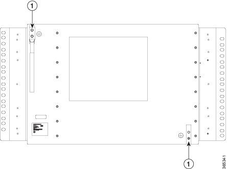
|
1 |
Grounding lug |
To ensure that the chassis ground connection that you provide is adequate, you need the following parts and tools:
- Ratcheting torque screwdriver with Phillips head that exerts up to 15 in.-lb (1.69 N-m) of pressure for attaching the ground wire to the router
- Crimping tool as specified by the ground lug manufacturer
- 6 or 8 AWG copper wire for the power cord
- 6 AWG or larger copper wire for the ground wire
- Wire-stripping tools appropriate to the wire you are using
 Caution | Before making connections to the Cisco NCS 4216, ensure that you disconnect the power at the circuit breaker. Otherwise, severe injury to you or damage to the router may occur. |
This equipment must be grounded. Never defeat the ground conductor or operate the equipment in the absence of a suitably installed ground conductor. Contact the appropriate cal inspection authority or an cian if you are uncertain that suitable grounding is available. Statement 1024
Warning | Use copper conductors only. Statement 1025 |
Warning | When installing the unit, the ground connection must always be made first and disconnected last. Statement 42 |
This unit is to be installed in a restrictive access location and must be permanently grounded to minimum 6 AWG copper ground wire.
Perform the following procedure to ground the Cisco NCS 4216 using a 2-hole lug and the corresponding mounting point. Most carriers require a minimum 6 AWG ground connection. Verify your carrier’s requirements for the ground connection.
1. If your ground wire is insulated, use a wire-stripping tool to strip the ground wire to 0.5 inch ± 0.02 inch (12.7 mm ±0.5 mm).
2. Slide the open end of your 2-hole ground lug over the exposed area of the ground wire.
3. Using a crimping tool (as specified by the ground lug manufacturer), crimp the ground lug to the ground wire as shown in the figure below.
4. Use a Phillips head screwdriver to attach the 2-hole ground lug and wire assembly to the router with the 2 pan-head Phillips head screws. For a 23-inch EIA rack, attach the 2-hole ground lug to the rear of the router.
5. Connect the other end of the ground wire to a suitable grounding point at your site.
DETAILED STEPS
| Step 1 | If your ground wire is insulated, use a wire-stripping tool to strip the ground wire to 0.5 inch ± 0.02 inch (12.7 mm ±0.5 mm). |
| Step 2 | Slide the open end of your 2-hole ground lug over the exposed area of the ground wire. |
| Step 3 | Using a crimping tool (as specified by the ground lug manufacturer), crimp the ground lug to the ground wire as shown in the figure below. |
| Step 4 | Use a Phillips head screwdriver to attach the 2-hole ground lug and wire assembly to the router with the 2 pan-head Phillips head screws. For a 23-inch EIA rack, attach the 2-hole ground lug to the rear of the router. |
| Step 5 | Connect the other end of the ground wire to a suitable grounding point at your site. |
Installing the Fan Tray
The fan tray is a modular unit that provides cooling to the Cisco NCS 4216. Follow these steps to install the fan tray in the chassis:
Note | Do not introduce body parts or objects in the fan tray slot when installing or removing the fan tray module. Exposed circuitry is an energy hazard. |
1. Orient the fan tray so that the captive screws are on the left side of the fan tray’s front panel. The following figure shows how to orient the fan tray.
2. Guide the fan tray into the chassis until it is fully seated.
3. Secure the fan tray to the chassis using the attached captive installation screws. The recommended maximum torque is 5.5 in.-lb (.62 N-m).
DETAILED STEPS
| Step 1 | Orient the fan tray so that the captive screws are on the left side of the fan tray’s front panel. The following figure shows how to orient the fan tray.
 | ||||
| Step 2 | Guide the fan tray into the chassis until it is fully seated.
| ||||
| Step 3 | Secure the fan tray to the chassis using the attached captive
installation screws. The recommended maximum torque is 5.5 in.-lb (.62 N-m).
This completes the procedure for installing or replacing the fan tray in a Cisco NCS 4216. For information about connecting cables to the fan tray alarm port, see the Connecting the Fan Tray Alarm Port section. For a summary of the LEDs on the fan tray, see the LED Summary section. For more information about air flow guidelines, see Air Flow Guidelines section. |
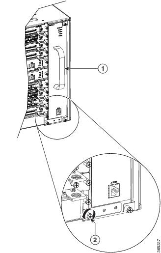
Removing and Replacing the Dust Filter
The chassis is shipped with a blank fan filter cover. To install the dust filter:
1. Remove the blank fan filter cover (A907-FAN-F=) by unscrewing the captive installation screws at the top and bottom of the dust filter frame. See the figure below.
2. Slide the new dust filter (A907-FAN-F) onto the fan tray.
3. Secure the filter with the top and bottom captive screws, in the chassis.
DETAILED STEPS
| Step 1 | Remove the blank fan filter cover (A907-FAN-F=) by unscrewing the captive installation screws at the top and bottom of the dust filter frame. See the figure below.
| ||
| Step 2 | Slide the new dust filter (A907-FAN-F) onto the fan tray. | ||
| Step 3 | Secure the filter with the top and bottom captive screws, in the
chassis.
|
Removing the Dust Filter
|
1 |
Captive screw |
2 |
Fan filter |
The dust filter must be removed for cleaning or for a replacement.
Dust Filter Maintenance
A periodic health check of the filter, every 3 months based on the level of dust in the environment helps in avoiding over clogging of the filters and provide better life. The product's filter may be used as a single use or reused depending upon the local deployment needs. If reuse of the filter is prohibited, it may be replaced every six months with PID (A907-FAN-F=) or equivalent.
If reused, this filter media may be cleaned with slightly compressed air, vacuumed, and/or rinsed with clean water. If a degreaser is required, use only a mild detergent, such as, dish washing liquid.
Caution | Avoid using harsh solvents or cleaning agents. |
If filters are cleaned with water, the filters should be completely dry before reinstalling. Even though this type of filter may be cleaned, replacement is recommended every two to three years to ensure media durability and eliminate residual dust build-up and subsequent air flow resistance.
Removing and Replacing the Fan Tray
The fan tray supports online insertion and removal (OIR). There is no need to power down the Cisco NCS 4216 to remove or replace the fan tray. However, the router will shut down if the fan tray is removed from the chassis for more than 90 seconds at 25º C due to thermal overload condition. Once the thermal overload condition is absent, the system attempts to power up automatically, if the Fan tray is re-inserted and the system temperature is within limits. Approximately at 25º C the system powers back in 2 minutes.
Note | If the FAN tray is removed and not replaced within the stipulated time then the system will automatically power off. If the system is powered off, then the DC input should be turned off for at least 30 seconds for all the PSU in the system simultaneously, and then turned on for the router to power on. |
Note | Do not introduce body parts or objects in the fan tray slot when installing or removing the fan tray module. Exposed circuitry is an energy hazard. |
Caution | The router can stay active for up to 60 seconds if the temperature is below the ambient limit. However, in the event of an overtemperature alarm, the router can shut down in less than 60 seconds. In the event of a critical temperature alarm, the router shuts down immediately. |
Caution | To avoid erroneous failure messages, allow at least 2 minutes for the system to reinitialize after the fan tray has been removed or replaced. |
Follow these steps to remove and replace the fan tray on the Cisco NCS 4216:
1. Using a No. 2 Phillips screwdriver or your fingers, loosen the captive installation screw that secures the fan tray to the chassis. The following figure shows the front of the fan tray, including the captive installation screws.
2. Grasp the fan tray handle with one hand and the outside of the chassis with the other hand. The figure above shows the front of the fan tray, including the handle.
3. Pull the fan tray toward you no more than 1 inch to disengage it from the power receptacle on the midplane, as shown in the following figure.
DETAILED STEPS
| Step 1 | Using a No. 2 Phillips screwdriver or your fingers, loosen the captive installation screw that secures the fan tray to the chassis. The following figure shows the front of the fan tray, including the captive installation screws.
| |||||||||||||||
| Step 2 | Grasp the fan tray handle with one hand and the outside of the chassis with the other hand. The figure above shows the front of the fan tray, including the handle.
| |||||||||||||||
| Step 3 | Pull the fan tray toward you no more than 1 inch to disengage it from the power receptacle on the midplane, as shown in the following figure.
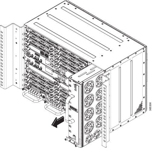
This completes the steps for removing the fan tray from the chassis.
To install the new fan tray, follow the steps in the Installing the Fan Tray section. The following table shows the fan OIR timelines.
|
RSP Installation
Follow the steps in the sections below on handling an RSP module in the Cisco NCS 4216:
Installing an RSP Module
To install an RSP module in the router chassis, perform the following steps:
1. Choose a slot for the module. Make sure that there is enough clearance to accommodate any equipment that will be connected to the ports on the module. If a blank module filler plate is installed in the slot in which you plan to install the module, remove the plate by removing its 2 Phillips pan-head screws.
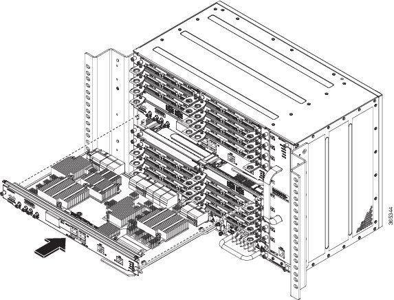
2. Fully open both the ejector levers on the new module, as shown in the figure below.
3. Position the module in the slot. Make sure that you align the sides of the module with the guides on each side of the slot, as shown in the figure below.
4. Carefully slide the module into the slot until the EMI gasket on the module makes contact with the module in the adjacent slot and both the ejector levers have closed to approximately 45 degrees with respect to the module faceplate.
5. While pressing down, simultaneously close both the ejector levers to fully seat the module in the backplane connector. The ejector levers are fully closed when they are flush with the module faceplate.
6. Tighten the two captive installation screws on the module. The recommended maximum torque is 5.5 in.-lb (.62 N-m).
7. Verify that the captive installation screws are tightened on all of the modules installed in the chassis. This step ensures that the EMI gaskets on all the modules are fully compressed in order to maximize the opening space for the new or replacement module.
DETAILED STEPS
| Step 1 | Choose a slot for the module. Make sure that there is enough clearance to accommodate any equipment that will be connected to the ports on the module. If a blank module filler plate is installed in the slot in which you plan to install the module, remove the plate by removing its 2 Phillips pan-head screws. | ||||||
| Step 2 | Fully open both the ejector levers on the new module, as shown in the figure below.
| ||||||
| Step 3 | Position the module in the slot. Make sure that you align the sides of the module with the guides on each side of the slot, as shown in the figure below.
 | ||||||
| Step 4 | Carefully slide the module into the slot until the EMI gasket on
the module makes contact with the module in the adjacent slot and both the
ejector levers have closed to approximately 45 degrees with respect to the
module faceplate.
| ||||||
| Step 5 | While pressing down, simultaneously close both the ejector levers to fully seat the module in the backplane connector. The ejector levers are fully closed when they are flush with the module faceplate. | ||||||
| Step 6 | Tighten the two captive installation screws on the module. The
recommended maximum torque is 5.5 in.-lb (.62 N-m).
| ||||||
| Step 7 | Verify that the captive installation screws are tightened on all
of the modules installed in the chassis. This step ensures that the EMI gaskets
on all the modules are fully compressed in order to maximize the opening space
for the new or replacement module.
|
Removing an RSP Module
Before you remove an RSP from the router, you should save the current configuration on a TFTP server or an external USB flash drive, using the copy running-config {ftp | tftp | bootflash:} command. This saves you time when bringing the module back online.
If the module is running Cisco IOS software, save the current running configuration by entering the copy running-config startup-config command.
Warning | Hazardous voltage or energy is present on the backplane when the system is operating. Use caution when servicing. Statement 1034 |
Warning | Invisible laser radiation may be emitted from disconnected fibers or connectors. Do not stare into beams or view directly with optical instruments. Statement 1051 |
To remove an RSP module, perform the following steps:
1. Disconnect any cables attached to the ports on the module.
2. Verify that the captive installation screws on all the modules in the chassis are tight. This step ensures that the space created by the removed module is maintained.
3. Loosen the two captive installation screws on the module you plan to remove from the chassis.
4. Place your thumbs on the ejector levers (see Cisco NCS 4216 RSP Installation figure ) and simultaneously rotate the ejector levers outward to unseat the module from the backplane connector.
5. Grasp the front edge of the module and slide the module straight out of the slot. If the chassis has horizontal slots, place your hand under the module to support its weight as you slide it out from the slot. Do not touch the module circuitry.
6. Place the module on an antistatic mat or antistatic foam, or immediately reinstall the module in another slot.
7. Install blank module filler plates (Cisco part number A90X-RSPA-BLANK-W) in empty slots, if any.
DETAILED STEPS
| Step 1 | Disconnect any cables attached to the ports on the module. | ||
| Step 2 | Verify that the captive installation screws on all the modules in
the chassis are tight. This step ensures that the space created by the removed
module is maintained.
| ||
| Step 3 | Loosen the two captive installation screws on the module you plan to remove from the chassis. | ||
| Step 4 | Place your thumbs on the ejector levers (see Cisco NCS 4216 RSP Installation figure ) and simultaneously rotate the ejector levers outward to unseat the module from the backplane connector. | ||
| Step 5 | Grasp the front edge of the module and slide the module straight
out of the slot. If the chassis has horizontal slots, place your hand under the
module to support its weight as you slide it out from the slot. Do not touch
the module circuitry.
| ||
| Step 6 | Place the module on an antistatic mat or antistatic foam, or immediately reinstall the module in another slot. | ||
| Step 7 | Install blank module filler plates (Cisco part number
A90X-RSPA-BLANK-W) in empty slots, if any.
|
Hot-Swapping an RSP Module
The Cisco NCS 4216 provides a feature that allows you to remove and replace a redundant RSP module without powering down the router. This feature, called hot-swapping or OIR, allows you to remove and replace a redundant module without disrupting router operation.
When two redundant modules are installed in the router, only one of the modules is active. The other one runs in standby mode, ready to take over processing if the active module fails.
When you remove or insert a redundant module while the router is powered on and running, the router does the following:
- Determines if there is sufficient power for the module.
- Scans the backplane for configuration changes.
- Initializes the newly inserted module. In addition, the system notes any removed modules and places those modules in the administratively shutdown state.
- Places any previously configured interfaces on the module back to the state they were in when they were removed. Any newly inserted interfaces are put in the administratively shutdown state as if they were present (but unconfigured) at boot time. If you insert the same type of module into a slot, its ports are configured and brought online up to the port count of the original module.
The router runs diagnostic tests on any new interfaces and the test results indicate the following:
- If the tests pass, the router is operating normally.
- If the new module is faulty, the router resumes normal operation but leaves the new interfaces disabled.
- If the diagnostic tests fail, the router stops operating, which usually indicates that the new module has a problem in the bus and should be removed.
Use the following guidelines when performing an OIR on an IM:
- Allow at least 2 minutes for the system to reinitialize before inserting a new IM.
- Avoid inserting a new IM during bootup until the active and standby RSPs have reached an OK state.
- When inserting multiple IMs into the chassis, wait until each IM reaches an OK state before inserting the next IM.
Interface Module Installation
The sections describe the various tasks of associated with interface module installation on the Cisco NCS 4216:
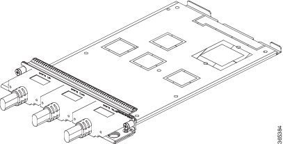
Installing an Interface Module
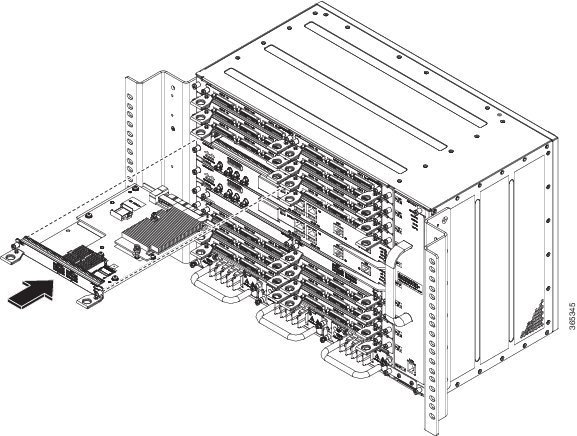
1. Before inserting an interface module, make sure that the chassis is grounded.
2. To insert the interface module, carefully align the edges of the interface module between the upper and lower edges of the router slot.
3. Carefully slide the interface module into the router slot until the interface module makes contact with the backplane. The following figure shows how to install the interface module.
4. Tighten the locking thumbscrews on both sides of the interface module. The recommended maximum torque is 5.5 in.-lb (.62 N-m).
5. Connect all the cables to each interface module.
DETAILED STEPS
| Step 1 | Before inserting an interface module, make sure that the chassis is grounded. |
| Step 2 | To insert the interface module, carefully align the edges of the interface module between the upper and lower edges of the router slot. |
| Step 3 | Carefully slide the interface module into the router slot until the interface module makes contact with the backplane. The following figure shows how to install the interface module.
 |
| Step 4 | Tighten the locking thumbscrews on both sides of the interface module. The recommended maximum torque is 5.5 in.-lb (.62 N-m). |
| Step 5 | Connect all the cables to each interface module. |
What to Do Next
Caution | Do not use interface module and power supply ejector handles to lift the chassis; using the handles to lift the chassis can deform or damage the handles. |
Removing an Interface Module
1. To remove an interface module, disconnect all the cables from each interface module.
2. Loosen the locking thumbscrews on both sides of the interface module.
3. Slide the interface module out of the router slot by pulling on the handles. If you are removing a blank filler plate, pull the blank filler plate completely out of the router slot using the captive screws.
DETAILED STEPS
| Step 1 | To remove an interface module, disconnect all the cables from each interface module. |
| Step 2 | Loosen the locking thumbscrews on both sides of the interface module. |
| Step 3 | Slide the interface module out of the router slot by pulling on the handles. If you are removing a blank filler plate, pull the blank filler plate completely out of the router slot using the captive screws. |
Hot-Swapping an Interface Module
The Cisco NCS 4216 provides a feature that allows you to remove and replace an interface module without powering down the router. This feature, called hot-swapping or OIR, allows you to remove and replace a redundant module without disrupting router operation.
The Cisco NCS 4216 does not support hot-swapping an interface module with another module of a different type. For example, you cannot swap an SFP Gigabit Ethernet module with a copper Gigabit Ethernet module without disrupting router operation.
- If the TDM interface module is swapped with the Gigabit Ethernet module in the same slot or vice-versa, the router must be reloaded.
If you perform OIR on an interface module and move the module to a different slot, the router does not retain the module configuration; you must reconfigure the interface module.
Replacing a configured interface module with a different interface module in the same slot is not supported on the router.
|
Interface Modules |
NCS4216-RSP/Cisco IOS Release 3.18.06v.S |
|---|---|
|
SFP Combo IM—8-port Gigabit Ethernet (8X1GE) + 1-port 10 Gigabit Ethernet (1X10GE) |
Swapping allowed on all Ethernet interface modules
|
|
8-port 10 Gigabit Ethernet Interface Module (8X10GE) |
|
|
1-port 100 Gigabit Ethernet Interface Module (1X100GE) |
|
|
2-port 40 Gigabit Ethernet QSFP Interface Module (2X40GE) |
|
|
OC-192 Interface Module with 8-port Low Rate CEM Interface Module (10G HO / 10G LO) |
No support |
|
48 x T1/E1 Interface Module |
|
|
48 X T3/E3 Interface Module |
When you remove or insert a redundant module while the router is powered on and running, the router does the following:
- Determines if there is sufficient power for the module.
- Scans the backplane for configuration changes.
- Initializes the newly inserted module. In addition, the system notes any removed modules and places those modules in the administratively shutdown state.
- Places any previously configured interfaces on the module back to the state they were in when they were removed.
The router runs diagnostic tests on any new interfaces and the test results indicate the following:
- If the tests pass, the router is operating normally.
- If the new module is faulty, the router resumes normal operation but leaves the new interfaces disabled.
- If the diagnostic tests fail, the router stops operating, which usually indicates that the new module has a problem in the bus and should be removed.
Caution | To avoid erroneous failure messages, note the current configuration of all interfaces before you remove or replace an interface module, and allow at least 2 minutes for the system to reinitialize after a module has been removed or replaced. This time is recommended in order to allow for synchronization between components within the interface module and for synchronization with the standby RSP. |
Installing the Power Supply
The Cisco NCS 4216 router provides the choice of the following power supply:
The DC power supply provides option to connect with two different sources (dual feed); positive (+) and negative (-) are marked on the PSU terminals.
Caution | The power supply must be wired before plugging the power supply in the chassis. Ensure the branch circuit breaker is turned off. Only after installing the power supply in the chassis, should the branch circuit breaker be turned on. The branch circuit breaker must be turned off before unplugging the power supply. |
Each power supply provides a dual primary input power connection.
Warning | Read the installation instructions before connecting the system to the power source. Statement 10 |
Caution | Do not use interface module and power supply ejector handles to lift the chassis; using the handles to lift the chassis can deform or damage the handles. |
- Preventing Power Loss
- Power Connection Guidelines
- Installing the DC Power Supply
- Removing and Replacing the DC Power Supply
Preventing Power Loss
Use the following guidelines to prevent power loss to the router.
- To prevent loss of input power, ensure that the total maximum load on each circuit supplying the power supplies is within the current ratings of the wiring and breakers.
- In some systems, you can use an UPS to protect against power failures at your site. Avoid UPS types that use ferroresonant technology. These UPS types can become unstable with systems like the Cisco NCS 4216, which can have substantial current draw fluctuations due to bursty data traffic patterns.
Use the information in the DC Power Supply Specifications table to estimate the power requirements and heat dissipation of a Cisco NCS 4216 based on a given configuration of the router. Determining power requirements is useful for planning the power distribution system needed to support the router.
Power Connection Guidelines
This section provides guidelines for connecting the Cisco NCS 4216 power supplies to the site power source.
Warning | Never defeat the ground conductor or operate the equipment in the absence of a suitably installed ground conductor. Contact the appropriate cal inspection authority or an cian if you are uncertain that suitable grounding is available. Statement 213 |
Warning | This product requires short-circuit (overcurrent) protection, to be provided as part of the building installation. Install only in accordance with national and local wiring regulations. Statement 1045 |
Guidelines for DC-Powered Systems
Basic guidelines for DC-powered systems include the following:
- Each chassis power supply should have its own dedicated input power source. The source must comply with the safety extra-low voltage (SELV) requirements in the UL 60950, CSA 60950, EN 60950, and IEC 60950 standards.
- The circuit must be protected by a dedicated two-pole circuit breaker. The circuit breaker should be sized according to the power supply input rating and local or national code requirements.
- The circuit breaker is considered the disconnect device and should be easily accessible.
- The system ground is the power supply and chassis ground.
- Do not connect the DC return wire to the system frame or to the system grounding equipment.
- Use the grounding lug to attach a wrist strap for ESD protection during servicing.
Installing the DC Power Supply
The sections describe how to install a DC power supply in the Cisco NCS 4216:
Note | This equipment is suitable for installation in Network Telecommunications Facilities and locations where the NEC applies. |
Note | This equipment is suitable for installations utilizing the Common Bonding Network (CBN). |
Note | The grounding architecture of this product is DC-Isolated (DC-I) for DC-powered products. DC-powered products have a nominal operating DC voltage of 48 VDC. |
- Installing the DC Power Supply Module
- Installing Terminal Block on the DC PEM Unit (A900-PWR900-D2)
- Activating the DC Power Supply
Installing the DC Power Supply Module
Perform the following procedure to install the power supply module:
1. Ensure that the system (earth) ground connection has been made. For ground connection installation instructions, see the Installing the Chassis Ground Connection section.
2. If necessary, remove the blank power supply filler plate from the chassis power supply bay opening by loosening the captive installation screws.
3. Verify that power to the DC circuit connected to the power supply you are installing is off. To ensure that power has been removed from the DC circuits, locate the circuit breakers for the DC circuits, switch the circuit breakers to the OFF position, and tape the circuit-breaker switches in the OFF position.
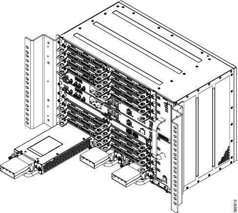
4. Grasp the power supply handle with one hand. Place your other hand underneath the power supply, as shown in the figure below. Slide the power supply into the power supply bay. Make sure that the power supply is fully seated in the bay.
5. Tighten the captive installation screws of the power supply. The recommended maximum torque is 5.5 in.-lb (.62 N-m).
DETAILED STEPS
| Step 1 | Ensure that the system (earth) ground connection has been made. For ground connection installation instructions, see the Installing the Chassis Ground Connection section. |
| Step 2 | If necessary, remove the blank power supply filler plate from the chassis power supply bay opening by loosening the captive installation screws. |
| Step 3 | Verify that power to the DC circuit connected to the power supply you are installing is off. To ensure that power has been removed from the DC circuits, locate the circuit breakers for the DC circuits, switch the circuit breakers to the OFF position, and tape the circuit-breaker switches in the OFF position. |
| Step 4 | Grasp the power supply handle with one hand. Place your other hand underneath the power supply, as shown in the figure below. Slide the power supply into the power supply bay. Make sure that the power supply is fully seated in the bay.
 |
| Step 5 | Tighten the captive installation screws of the power supply. The
recommended maximum torque is 5.5 in.-lb (.62 N-m).
If you are installing a redundant DC power supply, repeat these steps for the second power source. |
Installing Terminal Block on the DC PEM Unit (A900-PWR900-D2)
Perform the following procedure to install the terminal block.
1. Locate the terminal block plug.
2. Use a wire-stripping tool to strip the ends of each of the two wires coming from the DC-input power source to 0.27 inch (6.6 mm) ± 0.02 inch (0.5 mm) and the wire for grounding. Do not strip more than 0.29 inch (7.4 mm) of insulation from the wire. Stripping more than the recommended amount of wire can leave behind exposed wire from the terminal block plug after installation.
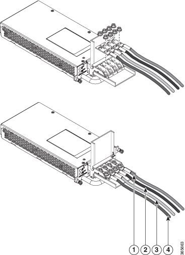
3. Identify the positive and negative feed positions for the terminal block connection. The recommended wiring sequence is (see the figure below):
4. Insert the exposed wire of one of the three DC-input power source wires into the terminal block plug. Make sure that you cannot see any wire lead. Only wire with insulation should extend from the terminal block.
5. Use a ratcheting torque screwdriver to torque the terminal block plug captive screw (above the installed wire lead) from 4.425 in.-lb (.5 N-m) to 5.310 in-lb (.6 N-m).
6. Repeat Step 4 through Step 5 for the remaining DC input power source wire and the ground wire.
7. Ensure that the terminal block plug is fully seated in the terminal block header on the DC power supply panel. The plug has a locking feature. You should hear a snap or click when it is installed properly.
8. Use a tie wrap to secure the wires to the rack, so that the wires are not pulled from the terminal block plug by casual contact. Make sure the tie wrap allows for some slack in the ground wire.
9. Use a tie wrap to secure the wires to the handle. Leave a service loop on the ground wire between the handle and the connector such that it is the last to receive strain if the wires are pulled.
DETAILED STEPS
| Step 1 | Locate the terminal block plug. | ||||||||
| Step 2 | Use a wire-stripping tool to strip the ends of each of the two wires coming from the DC-input power source to 0.27 inch (6.6 mm) ± 0.02 inch (0.5 mm) and the wire for grounding. Do not strip more than 0.29 inch (7.4 mm) of insulation from the wire. Stripping more than the recommended amount of wire can leave behind exposed wire from the terminal block plug after installation. | ||||||||
| Step 3 | Identify the positive and negative feed positions for the terminal block connection. The recommended wiring sequence is (see the figure below):
| ||||||||
| Step 4 | Insert the exposed wire of one of the three DC-input power source
wires into the terminal block plug. Make sure that you cannot see any wire
lead. Only wire with insulation should extend from the terminal block.
| ||||||||
| Step 5 | Use a ratcheting torque screwdriver to torque the terminal block plug captive screw (above the installed wire lead) from 4.425 in.-lb (.5 N-m) to 5.310 in-lb (.6 N-m). | ||||||||
| Step 6 | Repeat Step 4 through Step 5 for the remaining DC input power
source wire and the ground wire.
| ||||||||
| Step 7 | Ensure that the terminal block plug is fully seated in the terminal block header on the DC power supply panel. The plug has a locking feature. You should hear a snap or click when it is installed properly. | ||||||||
| Step 8 | Use a tie wrap to secure the wires to the rack, so that the wires are not pulled from the terminal block plug by casual contact. Make sure the tie wrap allows for some slack in the ground wire. | ||||||||
| Step 9 | Use a tie wrap to secure the wires to the handle. Leave a service loop on the ground wire between the handle and the connector such that it is the last to receive strain if the wires are pulled. |
What to Do Next
This completes the procedure for connecting the DC power supply in the Cisco NCS 4216.
If you are installing a redundant DC power supply, repeat these steps for the second power source.
Activating the DC Power Supply
Perform the following procedure to activate the DC power supply:
1. Remove the tape from the circuit-breaker switch handle, and restore power by moving the circuit-breaker switch handle to the On (|) position.
2. Verify power supply operation by checking if the power supply front panel LEDs are in the following states:
DETAILED STEPS
| Step 1 | Remove the tape from the circuit-breaker switch handle, and restore power by moving the circuit-breaker switch handle to the On (|) position. |
| Step 2 | Verify power supply operation by checking if the power supply
front panel LEDs are in the following states:
If the LEDs indicate a power problem, see the Troubleshooting section. If you are installing a redundant DC power supply, ensure that each power supply is connected to a separate power source in order to prevent power loss in the event of a power failure. If you are installing a redundant DC power supply, repeat these steps for the second power source. |
Removing and Replacing the DC Power Supply
This section provides information about removing and replacing the DC power supply in the Cisco NCS 4216.
Note | The Cisco NCS 4216 power supplies are hot-swappable. If you have installed redundant power supply modules, you can replace a single power supply without interrupting power to the router. |
Caution | To avoid erroneous failure messages, allow at least 2 minutes for the system to reinitialize after a power supply has been removed or replaced. |
Warning | When you install the unit, the ground connection must always be made first and disconnected last. Statement 1046 |
Warning | Before performing any of the following procedures, ensure that power is removed from the DC circuit. Statement 1003 |
Warning | Only trained and qualified personnel should be allowed to install, replace, or service this equipment. Statement 1030 |
Warning | Installation of the equipment must comply with local and national cal codes. Statement 1074 |
Follow these steps to remove and replace the DC power supply on the Cisco NCS 4216:
1. Before servicing the power supply, switch off the circuit breaker in your equipment area. As an additional precaution, tape the circuit-breaker switch in the Off position.
2. Slip on the ESD-preventive wrist strap that was included in the accessory kit.
3. Switch the power supply circuit-breaker switch to the Off (O) position.
4. Pull the terminal block plug connector out of the terminal block head in the power supply.
5. Loosen the captive screws on the DC power supply.
6. Grasping the power supply handle with one hand, pull the power supply out from the chassis while supporting it with the other hand.
7. Replace the DC power supply within 5 minutes. If the power supply bay is to remain empty, install a blank filler plate (Cisco part number NCS4216-PWR-BLANK) over the opening, and secure it with the captive installation screws.
DETAILED STEPS
| Step 1 | Before servicing the power supply, switch off the circuit breaker in your equipment area. As an additional precaution, tape the circuit-breaker switch in the Off position. |
| Step 2 | Slip on the ESD-preventive wrist strap that was included in the accessory kit. |
| Step 3 | Switch the power supply circuit-breaker switch to the Off (O) position. |
| Step 4 | Pull the terminal block plug connector out of the terminal block head in the power supply. |
| Step 5 | Loosen the captive screws on the DC power supply. |
| Step 6 | Grasping the power supply handle with one hand, pull the power supply out from the chassis while supporting it with the other hand. |
| Step 7 | Replace the DC power supply within 5 minutes. If the power supply bay is to remain empty, install a blank filler plate (Cisco part number NCS4216-PWR-BLANK) over the opening, and secure it with the captive installation screws. |
Connecting the Cisco NCS 4216 Router to the Network
The sections describe how to connect cables on the Cisco NCS 4216.
Note | When installing the cabling to the RSPs, we recommend that you leave a service loop of extra cabling sufficient to allow for fan tray removal. |
- Connecting Console Cables
- Connecting to the Auxiliary Port
- Connecting a Management Ethernet Cable
- Installing and Removing SFP
- Connecting a USB Flash Device
- Connecting Timing Cables
- Connecting a Cable to the GNSS Antenna Interface
- Connecting Ethernet Cables
- Connecting Cables to SFP Modules
- Connecting T1/E1 cables
- Connecting the Fan Tray Alarm Port
- Connector and Cable Specifications
Connecting Console Cables
The sections describe how to connect to the Cisco NCS 4216 using console cables.
Note | You cannot use the USB and RS232 console ports at the same time; if you insert the USB cable into the router, the RS232 port is disabled. |
- Connecting to the Serial Port using Microsoft Windows
- Connecting to the Console Port using Mac OS X
- Connecting to the Console Port using Linux
- Installing the Cisco Microsoft Windows USB Device Driver
- Uninstalling the Cisco Microsoft Windows USB Driver
Connecting to the Serial Port using Microsoft Windows
This procedure shows how to connect to the serial port using Microsoft Windows.
Note | Install the USB device driver before establishing a physical connection between the router and the PC, by using the USB Console cable plugged into the USB serial port. Otherwise, the connection will fail. For more information, see the Installing the Cisco Microsoft Windows USB Device Driver section. |
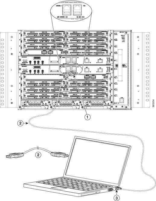
1. Connect the end of the console cable with the RJ45 connector to the light blue console port on the router. or Connect a USB Type A-to-Type A cable to the USB console port as shown in the figure below. If you are using the USB serial port for the first time on a Windows-based PC, install the USB driver now according to the instructions in the following sections.
2. Connect the end of the cable with the DB-9 connector (or USB Type-A) to the terminal or PC. If your terminal or PC has a console port that does not accommodate a DB-9 connector, you must provide an appropriate adapter for that port.
3. To communicate with the router, start a terminal emulator application, such as Microsoft Windows HyperTerminal. This software should be configured with the following parameters:
DETAILED STEPS
| Step 1 | Connect the end of the console cable with the RJ45 connector to the light blue console port on the router. or Connect a USB Type A-to-Type A cable to the USB console port as shown in the figure below. If you are using the USB serial port for the first time on a Windows-based PC, install the USB driver now according to the instructions in the following sections.
| ||||||||
| Step 2 | Connect the end of the cable with the DB-9 connector (or USB Type-A) to the terminal or PC. If your terminal or PC has a console port that does not accommodate a DB-9 connector, you must provide an appropriate adapter for that port. | ||||||||
| Step 3 | To communicate with the router, start a terminal emulator
application, such as Microsoft Windows HyperTerminal. This software should be
configured with the following parameters:
|
What to Do Next
Connecting to the Console Port using Mac OS X
This procedure describes how to connect a Mac OS X system USB port to the console using the built in OS X Terminal utility.
1. Use the Finder to go to Applications > Utilities > Terminal.
2. Connect the OS X USB port to the router.
3. Enter the following commands to find the OS X USB port number:
4. Connect to the USB port with the following command followed by the router USB port speed
DETAILED STEPS
| Step 1 | Use the Finder to go to Applications > Utilities > Terminal. |
| Step 2 | Connect the OS X USB port to the router. |
| Step 3 | Enter the following commands to find the OS X USB port number:
Example: macbook:user$ cd /dev macbook:user$ ls -ltr /dev/*usb* crw-rw-rw- 1 root wheel 9, 66 Apr 1 16:46 tty.usbmodem1a21 DT-macbook:dev user$ |
| Step 4 | Connect to the USB port with the following command followed by
the router USB port speed
Example: macbook:user$ screen /dev/tty.usbmodem1a21 9600 To disconnect the OS X USB console from the Terminal window Enter Ctrl-a followed by Ctrl-\ |
Connecting to the Console Port using Linux
This procedure shows how to connect a Linux system USB port to the console using the built in Linux Terminal utility.
1. Open the Linux Terminal window.
2. Connect the Linux USB port to the router.
3. Enter the following commands to find the Linux USB port number
4. Connect to the USB port with the following command followed by the router USB port speed
DETAILED STEPS
| Step 1 | Open the Linux Terminal window. |
| Step 2 | Connect the Linux USB port to the router. |
| Step 3 | Enter the following commands to find the Linux USB port number
Example: root@usb-suse# cd /dev root@usb-suse /dev# ls -ltr *ACM* crw-r--r-- 1 root root 188, 0 Jan 14 18:02 ttyACM0 root@usb-suse /dev# |
| Step 4 | Connect to the USB port with the following command followed by
the router USB port speed
Example: root@usb-suse /dev# screen /dev/ttyACM0 9600 To disconnect the Linux USB console from the Terminal window Enter Ctrl-a followed by : then quit |
Installing the Cisco Microsoft Windows USB Device Driver
A USB device driver must be installed the first time a Microsoft Windows-based PC is connected to the USB serial port on the router.
- Installing the Cisco Microsoft Windows XP USB Driver
- Installing the Cisco Microsoft Windows 2000 USB Driver
- Installing the Cisco Microsoft Windows Vista USB Driver
Installing the Cisco Microsoft Windows XP USB Driver
This procedure shows how to install the Microsoft Windows XP USB driver. Download the driver for your router model from the Tools and Resources Download Software site, USB Console Software category, at the following URL:
http://tools.cisco.com/support/downloads/go/Redirect.x?mdfid=268437899
1. Unzip the file Cisco_usbconsole_driver_X_X.zip (where X is a revision number).
2. If using 32-bit Windows XP double-click the file setup.exe from the Windows_32 folder, or if using 64-bit Windows XP double-click the file setup(x64).exe from the Windows_64 folder.
3. The Cisco Virtual Com InstallShield Wizard begins. Click Next.
4. The Ready to Install the Program window appears, Click Install.
5. The InstallShield Wizard Completed window appears. Click Finish.
6. Connect the USB cable to the PC and router USB console ports. The EN LED for the USB console port turns green, and within a few moments the Found New Hardware Wizard appears. Following the instructions to complete the installation of the driver.
7. The USB console is ready for use.
DETAILED STEPS
| Step 1 | Unzip the file Cisco_usbconsole_driver_X_X.zip (where X is a revision number). |
| Step 2 | If using 32-bit Windows XP double-click the file setup.exe from the Windows_32 folder, or if using 64-bit Windows XP double-click the file setup(x64).exe from the Windows_64 folder. |
| Step 3 | The Cisco Virtual Com InstallShield Wizard begins. Click Next. |
| Step 4 | The Ready to Install the Program window appears, Click Install. |
| Step 5 | The InstallShield Wizard Completed window appears. Click Finish. |
| Step 6 | Connect the USB cable to the PC and router USB console ports. The EN LED for the USB console port turns green, and within a few moments the Found New Hardware Wizard appears. Following the instructions to complete the installation of the driver. |
| Step 7 | The USB console is ready for use. |
Installing the Cisco Microsoft Windows 2000 USB Driver
This procedure shows how to install the Microsoft Windows 2000 USB driver.
1. Obtain the file Cisco_usbconsole_driver.zip from the Cisco.com web site and unzip it.
2. Double-click the file setup.exe.
3. The Cisco Virtual Com InstallShield Wizard begins. Click Next.
4. The Ready to Install the Program window appears, Click Install.
5. The InstallShield Wizard Completed window appears. Click Finish.
6. Connect the USB cable to the PC and router USB console ports. The EN LED for the USB console port turns green, and within a few moments a series of Found New Hardware Wizard windows appear. Following the instructions to complete the installation of the driver.
7. The USB console is ready for use.
DETAILED STEPS
| Step 1 | Obtain the file Cisco_usbconsole_driver.zip from the Cisco.com web site and unzip it. |
| Step 2 | Double-click the file setup.exe. |
| Step 3 | The Cisco Virtual Com InstallShield Wizard begins. Click Next. |
| Step 4 | The Ready to Install the Program window appears, Click Install. |
| Step 5 | The InstallShield Wizard Completed window appears. Click Finish. |
| Step 6 | Connect the USB cable to the PC and router USB console ports. The EN LED for the USB console port turns green, and within a few moments a series of Found New Hardware Wizard windows appear. Following the instructions to complete the installation of the driver. |
| Step 7 | The USB console is ready for use. |
Installing the Cisco Microsoft Windows Vista USB Driver
This procedure shows how to install the Microsoft Windows Vista USB driver.
1. Obtain the file Cisco_usbconsole_driver.zip from the Cisco.com web site and unzip it.
2. If using 32-bit Windows Vista double-click the file setup.exe from the Windows_32 folder, or if using 64-bit Windows Vista double-click the file setup(x64).exe from the Windows_64 folder.
3. The Cisco Virtual Com InstallShield Wizard begins. Click Next.
4. The Ready to Install the Program window appears, Click Install.
5. The InstallShield Wizard Completed window appears. Click Finish.
6. Connect the USB cable to the PC and router USB console ports. The EN LED for the USB console port turns green, and within a few moments a pop up window stating “Installing device driver software” appears. Following the instructions to complete the installation of the driver.
7. The USB console is ready for use.
DETAILED STEPS
| Step 1 | Obtain the file Cisco_usbconsole_driver.zip from the Cisco.com web site and unzip it. | ||
| Step 2 | If using 32-bit Windows Vista double-click the file setup.exe from the Windows_32 folder, or if using 64-bit Windows Vista double-click the file setup(x64).exe from the Windows_64 folder. | ||
| Step 3 | The Cisco Virtual Com InstallShield Wizard begins. Click Next. | ||
| Step 4 | The Ready to Install the Program window appears, Click Install.
| ||
| Step 5 | The InstallShield Wizard Completed window appears. Click Finish. | ||
| Step 6 | Connect the USB cable to the PC and router USB console ports. The EN LED for the USB console port turns green, and within a few moments a pop up window stating “Installing device driver software” appears. Following the instructions to complete the installation of the driver. | ||
| Step 7 | The USB console is ready for use. |
Uninstalling the Cisco Microsoft Windows USB Driver
This section provides instructions for how to uninstall the Cisco Microsoft Windows USB device driver.
- Uninstalling the Cisco Microsoft Windows XP and 2000 USB Driver
- Uninstalling the Cisco Microsoft Windows XP and 2000 USB Driver
- Uninstalling the Cisco Microsoft Windows Vista USB Driver
Uninstalling the Cisco Microsoft Windows XP and 2000 USB Driver
Uninstalling the Cisco Microsoft Windows XP and 2000 USB Driver
This procedure shows you how to uninstall both the Microsoft Windows XP and 2000 USB driver. The driver can be removed using the Windows Add Remove Programs utility or the setup.exe program.
Using the Add Remove Programs Utility
Note | Disconnect the router console terminal before uninstalling the driver. |
1. Click Start > Control Panel > Add or Remove Programs.
2. Scroll to Cisco Virtual Com and click Remove.
3. When the Program Maintenance window appears, select the Remove radio button. Click Next.
DETAILED STEPS
Uninstalling the Cisco Microsoft Windows Vista USB Driver
This procedure shows you how to uninstall the Microsoft Windows Vista USB driver.
Note | Disconnect the router console terminal before uninstalling the driver. |
1. Run the setup.exe for Windows 32-bit or setup(x64).exe for Windows-64bit. Click Next.
2. The InstallShield Wizard for Cisco Virtual Com appears. Click Next.
3. When the Program Maintenance window appears, select the Remove radio button. Click Next.
4. When the Remove the Program window appears, click Remove.
5. When the InstallShield Wizard Completed window appears click Finish.
DETAILED STEPS
| Step 1 | Run the setup.exe for Windows 32-bit or setup(x64).exe for Windows-64bit. Click Next. | ||
| Step 2 | The InstallShield Wizard for Cisco Virtual Com appears. Click Next. | ||
| Step 3 | When the Program Maintenance window appears, select the Remove radio button. Click Next. | ||
| Step 4 | When the Remove the Program window appears, click Remove.
| ||
| Step 5 | When the InstallShield Wizard Completed window appears click Finish. |
What to Do Next
Note
Connecting to the Auxiliary Port
When a modem is connected to the auxiliary port, a remote user can dial in to the router and configure it. Use a light blue console cable and the DB-9-to-DB-25 connector adapter.
Note | The console cable and DB-9-to-DB-25 connector are not included with the Cisco NCS 4216; they are ordered separately. |
To connect a modem to the router, follow these steps:
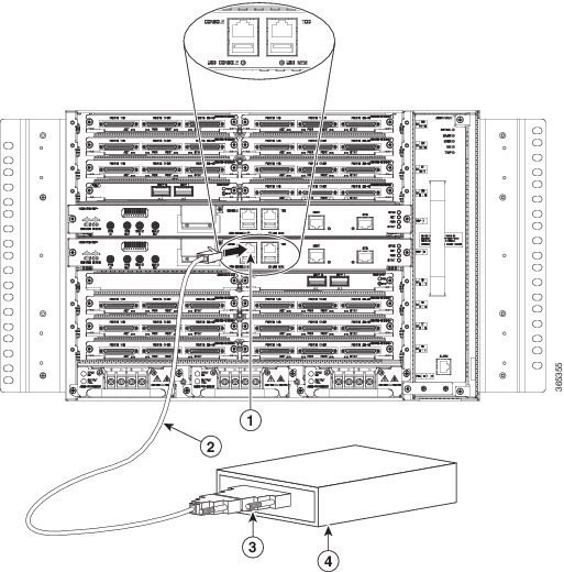
1. Connect the RJ45 end of the adapter cable to the black AUX port on the router, as shown in the figure below.
2. Connect the DB-9 end of the console cable to the DB-9 end of the modem adapter.
3. Connect the DB-25 end of the modem adapter to the modem.
4. Make sure that your modem and the router auxiliary port are configured for the same transmission speed (up to 115200 bps is supported) and for mode control with data carrier detect (DCD) and data terminal ready (DTR) operations.
DETAILED STEPS
| Step 1 | Connect the RJ45 end of the adapter cable to the black AUX port on the router, as shown in the figure below.
| ||||||||
| Step 2 | Connect the DB-9 end of the console cable to the DB-9 end of the modem adapter. | ||||||||
| Step 3 | Connect the DB-25 end of the modem adapter to the modem. | ||||||||
| Step 4 | Make sure that your modem and the router auxiliary port are configured for the same transmission speed (up to 115200 bps is supported) and for mode control with data carrier detect (DCD) and data terminal ready (DTR) operations. |
Connecting a Management Ethernet Cable
When using the Ethernet Management port in the default mode (speed-auto and duplex-auto) the port operates in auto-MDI/MDI-X mode. The port automatically provides the correct signal connectivity through the Auto-MDI/MDI-X feature. The port automatically senses a crossover or straight-through cable and adapts to it.
However, when the Ethernet Management port is configured to a fixed speed (10 or 100 Mbps) through command-line interface (CLI) commands, the port is forced to MDI mode.
When in a fixed-speed configuration and MDI mode:
- Use a crossover cable to connect to an MDI port
- Use a straight-through cable to connect to an MDI-X port
Warning | To comply with the Telcordia GR-1089 NEBS standard for electromagnetic compatibility and safety, connect the Management Ethernet ports only to intra-building or unexposed wiring or cable. The intrabuilding cable must be shielded and the shield must be grounded at both ends. The intra-building port(s) of the equipment or subassembly must not be metallically connected to interfaces that connect to the OSP or its wiring. These interfaces are designed for use as intra-building interfaces only (Type 2 or Type 4 ports as described in GR-1089-CORE) and require isolation from the exposed OSP cabling. The addition of Primary Protectors is not sufficient protection in order to connect these interfaces metallically to OSP wiring. |
Installing and Removing SFP
The Cisco NCS 4216 supports a variety of SFP modules, including optical and Ethernet modules. For information on how to install and remove SFP modules, see the documentation for the SFP module at
For information about inspecting and cleaning fiber-optic connections, see http://www.cisco.com/en/US/partner/tech/tk482/tk876/technologies_white_paper09186a0080254eba.shtml
Caution | We recommend that you wait 30 seconds between removal and insertion of an SFP on an interface module. This time is recommended to allow the transceiver software to initialize and synchronize with the standby RSP. Changing an SFP more quickly could result in transceiver initialization issues that disable the SFP. |
Connecting a USB Flash Device
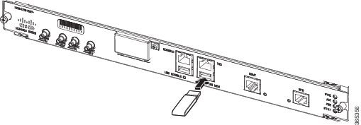
To connect a USB flash device to the Cisco NCS 4216, insert the memory stick in the USB port labeled MEM. The Flash memory module can be inserted in only one way, and can be inserted or removed regardless of whether the router is powered up or not.
The following figure shows the USB port connector on the Cisco NCS 4216.
Removing a USB Flash Device
To remove and then replace a USB flash token memory stick from a Cisco NCS 4216, follow these steps:
1. Pull the memory stick from the USB port.
2. To replace a Cisco USB Flash memory stick, simply insert the module into the USB port labeled MEM as shown in the Cisco NCS 4216 Flash Token Memory Stick figure. The Flash memory module can be inserted in only one way, and can be inserted or removed regardless of whether the router is powered up or not.
DETAILED STEPS
| Step 1 | Pull the memory stick from the USB port. | ||
| Step 2 | To replace a Cisco USB Flash memory stick, simply insert the module into the USB port labeled MEM as shown in the Cisco NCS 4216 Flash Token Memory Stick figure. The Flash memory module can be inserted in only one way, and can be inserted or removed regardless of whether the router is powered up or not.
This completes the USB Flash memory installation procedure. |
Connecting Timing Cables
The sections describe how to connect timing cables to the Cisco NCS 4216:
Note | When installing the cabling to the RSPs, we recommend that you leave a service loop of extra cabling sufficient to allow for fan tray removal. |
Connecting Cables to the BITS Interface
The following steps describe how to connect a cable to the router BITS port:
1. Confirm that the router is powered off.
2. Connect one end of the cable to the BITS port using a straight-through, shielded RJ48C-to-RJ48C cable.
3. Connect the other end to the BTS patch or demarcation panel at your site.
4. Turn on power to the router.
DETAILED STEPS
| Step 1 | Confirm that the router is powered off. | ||||
| Step 2 | Connect one end of the cable to the BITS port using a straight-through, shielded RJ48C-to-RJ48C cable. | ||||
| Step 3 | Connect the other end to the BTS patch or demarcation panel at your site. | ||||
| Step 4 | Turn on power to the router.
For information about the BITS port pinouts, see the Troubleshooting section.
|
Connecting Cables to a GNSS Interface
The sections describe how to connect cables from the Cisco NCS 4216 to a GPS unit for input or output timing of frequency:
Note | A Y-cable is required to connect to a primary and backup RSP in order to ensure that the router continues to transmit timing signals in the event of a network failure. For a mini-coax connection, this Y-cable can be part number CAB-BNC-7INY (7 inch BNC Y-cable). For an Ethernet connection, this Y-cable can be a RJ45 Cat5 1-to-2 splitter (3 female port RJ45 connector). |
Note | When installing the cabling to the RSPs, we recommend that you leave a service loop of extra cabling sufficient to allow for fan tray removal. |
- Connecting Cables to the Input 10Mhz or 1PPS Interface
- Connecting Cables to the Output 10Mhz or 1PPS Interface
- Connecting Cables to the ToD Interface
Connecting Cables to the Input 10Mhz or 1PPS Interface
1. Connect one end of a mini-coax Y-cable to the GPS unit.
2. Connect one end of the split-side Y-cable mini-coax to the 10Mhz or 1PPS port on the primary RSP of the Cisco NCS 4216.
3. Connect the other end of the split-side Y-cable mini-coax to the 10Mhz or 1PPS port on the backup RSP of the Cisco NCS 4216.
DETAILED STEPS
| Step 1 | Connect one end of a mini-coax Y-cable to the GPS unit. |
| Step 2 | Connect one end of the split-side Y-cable mini-coax to the 10Mhz or 1PPS port on the primary RSP of the Cisco NCS 4216. |
| Step 3 | Connect the other end of the split-side Y-cable mini-coax to the 10Mhz or 1PPS port on the backup RSP of the Cisco NCS 4216. |
Connecting Cables to the Output 10Mhz or 1PPS Interface
1. Connect one end of a mini-coax Y-cable to the Slave unit.
2. Connect one end of the split-side Y-cable mini-coax to the 10Mhz or 1PPS port on the primary RSP of the Cisco NCS 4216.
3. Connect the other end of the split-side Y-cable mini-coax to the 10Mhz or 1PPS port on the backup RSP of the Cisco NCS 4216.
DETAILED STEPS
| Step 1 | Connect one end of a mini-coax Y-cable to the Slave unit. |
| Step 2 | Connect one end of the split-side Y-cable mini-coax to the 10Mhz or 1PPS port on the primary RSP of the Cisco NCS 4216. |
| Step 3 | Connect the other end of the split-side Y-cable mini-coax to the 10Mhz or 1PPS port on the backup RSP of the Cisco NCS 4216. |
Connecting Cables to the ToD Interface
1. Connect one end of a straight-through Ethernet cable to the GPS unit.
2. Connect one end of the split-side Y-cable Ethernet to the ToD port on the primary RSP of the Cisco NCS 4216.
3. Connect the other end of the split-side Y-cable Ethernet to the ToD port on the backup RSP of the Cisco NCS 4216.
DETAILED STEPS
| Step 1 | Connect one end of a straight-through Ethernet cable to the GPS unit. | ||||||
| Step 2 | Connect one end of the split-side Y-cable Ethernet to the ToD port on the primary RSP of the Cisco NCS 4216. | ||||||
| Step 3 | Connect the other end of the split-side Y-cable Ethernet to the
ToD port on the backup RSP of the Cisco NCS 4216.
|
Connecting a Cable to the GNSS Antenna Interface
Note | The GNSS module is not hot swappable. |
1. Connect one end of a shielded coaxial cable to the GNSS RF IN port.
2. Connect the other end of the shielded coaxial cable to the GNSS antenna after the primary protector.
DETAILED STEPS
| Step 1 | Connect one end of a shielded coaxial cable to the GNSS RF IN port. | ||||||
| Step 2 | Connect the other end of the shielded coaxial cable to the GNSS
antenna after the primary protector.
|
Connecting Ethernet Cables
The Cisco NCS 4216 interface modules support RJ45 or SFP Ethernet ports. For instructions on how to connect cables to Ethernet SFP ports, see the Connecting Cables to SFP Modules section.
The RJ45 port supports standard straight-through and crossover Category 5 unshielded twisted-pair (UTP) cables. Cisco Systems does not supply Category 5 UTP cables; these cables are available commercially.
Warning | To comply with the Telcordia GR-1089 NEBS standard for electromagnetic compatibility and safety, connect the Gigabit Ethernet ports only to intra-building or unexposed wiring or cable. The intrabuilding cable must be shielded and the shield must be grounded at both ends. The intra-building port(s) of the equipment or subassembly must not be metallically connected to interfaces that connect to the OSP or its wiring. These interfaces are designed for use as intra-building interfaces only (Type 2 or Type 4 ports as described in GR-1089-CORE) and require isolation from the exposed OSP cabling. The addition of Primary Protectors is not sufficient protection in order to connect these interfaces metallically to OSP wiring. |
Note | When installing the cabling to the RSPs, we recommend that you leave a service loop of extra cabling sufficient to allow for fan tray removal. |
Follow these steps to connect the cable to a copper Gigabit Ethernet port:
1. Confirm that the router is powered off.
2. Connect one end of the cable to the Gigabit Ethernet port on the router.
3. Connect the other end to the BTS patch or demarcation panel at your site.
DETAILED STEPS
Connecting Cables to SFP Modules
For information on connecting cables to Cisco optical and Ethernet SFP interfaces, see
Connecting T1/E1 cables
The physical layer interface for the Cisco NCS 4216 T1/E1 port is a customer-installed high-density connector. The high-density connector has thumbscrews which should be screwed into the interface when the cable is installed.
Note | Patch panels are required in order to connect the high-density interface connectors to individual T1/E1 lines. |
- Installing the Cable Connectors
- T1/E1 Pinouts
- RJ48 Cable Pinouts
- Patch Panel cables
- Connecting Cables to the Patch Panel
- Patch Panel Connectors
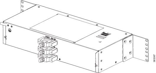
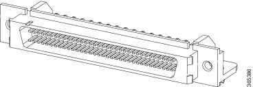
Installing the Cable Connectors
T1/E1 Cable Connectors
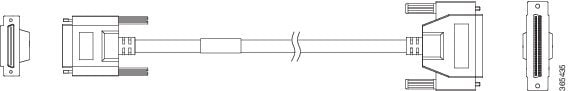
One end of the cable (see the figure above) has a 68-pin connector that plugs into the T1/E1 interface module. Use the thumbscrews on either side of the connector to secure the cable to the interface.
The other end of the cable has two 68-pin connectors that attach to the rear of a 48-port RJ48 or DIN patch panel.
T1/E1 Cable Connectors
One end of the cable (see Figure 3-22 ) has a 68-pin connector that plugs into the T1/E1 interface module. Use the thumbscrews on either side of the connector to secure the cable to the interface.
The other end of the cable has two 68-pin connectors that attach to the rear of a 48-port RJ48 or DIN patch panel.
T1/E1 Pinouts
For information about the pinout of the cable connecting the T1/E1 interface to the rear of the patch panel, see the T1/E1 Port Pinouts (RJ-48) section.
RJ48 Cable Pinouts
T1 lines from individual subscribers are attached to RJ45 connectors on the front of the 24-port patch panel. Each RJ45 port accommodates an individual T1 subscriber line.
For the T1/E1 ports, see the T1/E1 Port Pinouts (RJ-48) section.
Patch Panel cables
The patch panel cable connects the interface modules with the patch panel.
Each cable connects one VHDCI connector on the interface module to the connector on the patch panel. A set of three cables is required to connect one interface module to one 48-port patch panel.
The following table shows details of the patch panel cables:
|
Patch Panel Cable |
Description |
|---|---|
|
CABLE-16TDM-C |
16-port cable for TDM CEM Interface Module, no redundancy, 10 feet in length |
Note | CABLE-16TDM-C-R is not supported in Cisco IOS XE Release 3.18.06v.S. |
Connecting Cables to the Patch Panel
If you are connecting two T1/E1 interfaces to each other, you must cable both interfaces’ patch panels together using a T1 straight-through shielded cables. If both T1/E1 interfaces are connected to their patch panels in a different configuration, use a T1 straight-through cable (standard RJ48C patch cable) to connect the patch panels.
Warning | To comply with the Telcordia GR-1089 NEBS standard for electromagnetic compatibility and safety, connect the T1/E1 ports only to intra-building or unexposed wiring or cable. The intrabuilding cable must be shielded and the shield must be grounded at both ends. The intra-building port(s) of the equipment or subassembly must not be metallically connected to interfaces that connect to the OSP or its wiring. These interfaces are designed for use as intra-building interfaces only (Type 1 and Type 3 ports as described in GR-1089-CORE) and require isolation from the exposed OSP cabling. The addition of Primary Protectors is not sufficient protection in order to connect these interfaces metallically to OSP wiring. |
Patch Panel Connectors
The PANEL-48-1-DIN and PANEL-48-3-DIN provide 48 DIN 1.0/2.3 connectors on the front side of the patch panel. These connectors terminate to 75 ohm coaxial cable through the DIN plug.
The PANEL-48-1-RJ48 provide 48 RJ45 connector on the front side of the patch panel. These connectors terminate to 110 ohm T1/E1 cable through a RJ45 connector.
Connecting the Fan Tray Alarm Port
The fan tray includes an alarm port that maps to 4 dry contact alarm inputs.
The pins on the alarm port are passive signals and can be configured as Normally Open (an alarm generated when current is interrupted) or Normally Closed (an alarm is generated when a circuit is established) alarms. You can configure each alarm input as critical, major, or minor. An alarm triggers alarm LEDs and alarm messages. The relay contacts can be controlled through any appropriate third-party relay controller. The open/close configuration is an option controlled in IOS.
Warning | To comply with the Telcordia GR-1089 NEBS standard for electromagnetic compatibility and safety, connect the alarm ports only to intra-building or unexposed wiring or cable. The intrabuilding cable must be shielded and the shield must be grounded at both ends. The intra-building port(s) of the equipment or subassembly must not be metallically connected to interfaces that connect to the OSP or its wiring. These interfaces are designed for use as intra-building interfaces only (Type 2 or Type 4 ports as described in GR-1089-CORE) and require isolation from the exposed OSP cabling. The addition of Primary Protectors is not sufficient protection in order to connect these interfaces metallically to OSP wiring. |
Only Pins 1, 2, 4, 6, and 8 are available for customer use. The remaining pins are for Cisco manufacturing test, and should not be connected. Use a shielded cable for connection to this port for EMC protection. External Alarm Input Pinout table summarizes the pinouts on the alarm port in the Troubleshooting section.
1. Attach an RJ45 cable to the alarm port.
2. Attach the other end of the RJ45 cable to the relay controller.
DETAILED STEPS
What to Do Next
For information about how to map alarm inputs to critical, major, and minor alarm conditions, see the Cisco NCS 4216 Software Configuration Guide .
Connector and Cable Specifications
For more information on cable specifications and pinouts, see theTroubleshooting section.
 Feedback